EP2741018B1 - Treatment unit of the incoming air to a room - Google Patents
Treatment unit of the incoming air to a room Download PDFInfo
- Publication number
- EP2741018B1 EP2741018B1 EP13194785.5A EP13194785A EP2741018B1 EP 2741018 B1 EP2741018 B1 EP 2741018B1 EP 13194785 A EP13194785 A EP 13194785A EP 2741018 B1 EP2741018 B1 EP 2741018B1
- Authority
- EP
- European Patent Office
- Prior art keywords
- cooling circuit
- heat exchanger
- air
- treatment unit
- supply
- Prior art date
- Legal status (The legal status is an assumption and is not a legal conclusion. Google has not performed a legal analysis and makes no representation as to the accuracy of the status listed.)
- Active
Links
Images


Classifications
-
- F—MECHANICAL ENGINEERING; LIGHTING; HEATING; WEAPONS; BLASTING
- F24—HEATING; RANGES; VENTILATING
- F24F—AIR-CONDITIONING; AIR-HUMIDIFICATION; VENTILATION; USE OF AIR CURRENTS FOR SCREENING
- F24F3/00—Air-conditioning systems in which conditioned primary air is supplied from one or more central stations to distributing units in the rooms or spaces where it may receive secondary treatment; Apparatus specially designed for such systems
- F24F3/12—Air-conditioning systems in which conditioned primary air is supplied from one or more central stations to distributing units in the rooms or spaces where it may receive secondary treatment; Apparatus specially designed for such systems characterised by the treatment of the air otherwise than by heating and cooling
- F24F3/14—Air-conditioning systems in which conditioned primary air is supplied from one or more central stations to distributing units in the rooms or spaces where it may receive secondary treatment; Apparatus specially designed for such systems characterised by the treatment of the air otherwise than by heating and cooling by humidification; by dehumidification
- F24F3/1411—Air-conditioning systems in which conditioned primary air is supplied from one or more central stations to distributing units in the rooms or spaces where it may receive secondary treatment; Apparatus specially designed for such systems characterised by the treatment of the air otherwise than by heating and cooling by humidification; by dehumidification by absorbing or adsorbing water, e.g. using an hygroscopic desiccant
- F24F3/1423—Air-conditioning systems in which conditioned primary air is supplied from one or more central stations to distributing units in the rooms or spaces where it may receive secondary treatment; Apparatus specially designed for such systems characterised by the treatment of the air otherwise than by heating and cooling by humidification; by dehumidification by absorbing or adsorbing water, e.g. using an hygroscopic desiccant with a moving bed of solid desiccants, e.g. a rotary wheel supporting solid desiccants
-
- F—MECHANICAL ENGINEERING; LIGHTING; HEATING; WEAPONS; BLASTING
- F24—HEATING; RANGES; VENTILATING
- F24F—AIR-CONDITIONING; AIR-HUMIDIFICATION; VENTILATION; USE OF AIR CURRENTS FOR SCREENING
- F24F3/00—Air-conditioning systems in which conditioned primary air is supplied from one or more central stations to distributing units in the rooms or spaces where it may receive secondary treatment; Apparatus specially designed for such systems
- F24F3/12—Air-conditioning systems in which conditioned primary air is supplied from one or more central stations to distributing units in the rooms or spaces where it may receive secondary treatment; Apparatus specially designed for such systems characterised by the treatment of the air otherwise than by heating and cooling
- F24F3/14—Air-conditioning systems in which conditioned primary air is supplied from one or more central stations to distributing units in the rooms or spaces where it may receive secondary treatment; Apparatus specially designed for such systems characterised by the treatment of the air otherwise than by heating and cooling by humidification; by dehumidification
- F24F3/147—Air-conditioning systems in which conditioned primary air is supplied from one or more central stations to distributing units in the rooms or spaces where it may receive secondary treatment; Apparatus specially designed for such systems characterised by the treatment of the air otherwise than by heating and cooling by humidification; by dehumidification with both heat and humidity transfer between supplied and exhausted air
-
- F—MECHANICAL ENGINEERING; LIGHTING; HEATING; WEAPONS; BLASTING
- F24—HEATING; RANGES; VENTILATING
- F24F—AIR-CONDITIONING; AIR-HUMIDIFICATION; VENTILATION; USE OF AIR CURRENTS FOR SCREENING
- F24F5/00—Air-conditioning systems or apparatus not covered by F24F1/00 or F24F3/00, e.g. using solar heat or combined with household units such as an oven or water heater
- F24F5/0007—Air-conditioning systems or apparatus not covered by F24F1/00 or F24F3/00, e.g. using solar heat or combined with household units such as an oven or water heater cooling apparatus specially adapted for use in air-conditioning
- F24F5/001—Compression cycle type
-
- F—MECHANICAL ENGINEERING; LIGHTING; HEATING; WEAPONS; BLASTING
- F25—REFRIGERATION OR COOLING; COMBINED HEATING AND REFRIGERATION SYSTEMS; HEAT PUMP SYSTEMS; MANUFACTURE OR STORAGE OF ICE; LIQUEFACTION SOLIDIFICATION OF GASES
- F25B—REFRIGERATION MACHINES, PLANTS OR SYSTEMS; COMBINED HEATING AND REFRIGERATION SYSTEMS; HEAT PUMP SYSTEMS
- F25B13/00—Compression machines, plants or systems, with reversible cycle
-
- F—MECHANICAL ENGINEERING; LIGHTING; HEATING; WEAPONS; BLASTING
- F24—HEATING; RANGES; VENTILATING
- F24F—AIR-CONDITIONING; AIR-HUMIDIFICATION; VENTILATION; USE OF AIR CURRENTS FOR SCREENING
- F24F3/00—Air-conditioning systems in which conditioned primary air is supplied from one or more central stations to distributing units in the rooms or spaces where it may receive secondary treatment; Apparatus specially designed for such systems
- F24F3/044—Systems in which all treatment is given in the central station, i.e. all-air systems
- F24F2003/0448—Systems in which all treatment is given in the central station, i.e. all-air systems with two air ducts for separately transporting treated hot and cold air from the central station to the rooms
-
- F—MECHANICAL ENGINEERING; LIGHTING; HEATING; WEAPONS; BLASTING
- F24—HEATING; RANGES; VENTILATING
- F24F—AIR-CONDITIONING; AIR-HUMIDIFICATION; VENTILATION; USE OF AIR CURRENTS FOR SCREENING
- F24F2203/00—Devices or apparatus used for air treatment
- F24F2203/10—Rotary wheel
- F24F2203/1016—Rotary wheel combined with another type of cooling principle, e.g. compression cycle
-
- F—MECHANICAL ENGINEERING; LIGHTING; HEATING; WEAPONS; BLASTING
- F24—HEATING; RANGES; VENTILATING
- F24F—AIR-CONDITIONING; AIR-HUMIDIFICATION; VENTILATION; USE OF AIR CURRENTS FOR SCREENING
- F24F2203/00—Devices or apparatus used for air treatment
- F24F2203/10—Rotary wheel
- F24F2203/1032—Desiccant wheel
-
- F—MECHANICAL ENGINEERING; LIGHTING; HEATING; WEAPONS; BLASTING
- F24—HEATING; RANGES; VENTILATING
- F24F—AIR-CONDITIONING; AIR-HUMIDIFICATION; VENTILATION; USE OF AIR CURRENTS FOR SCREENING
- F24F2203/00—Devices or apparatus used for air treatment
- F24F2203/10—Rotary wheel
- F24F2203/104—Heat exchanger wheel
-
- F—MECHANICAL ENGINEERING; LIGHTING; HEATING; WEAPONS; BLASTING
- F24—HEATING; RANGES; VENTILATING
- F24F—AIR-CONDITIONING; AIR-HUMIDIFICATION; VENTILATION; USE OF AIR CURRENTS FOR SCREENING
- F24F2203/00—Devices or apparatus used for air treatment
- F24F2203/10—Rotary wheel
- F24F2203/1072—Rotary wheel comprising two rotors
-
- F—MECHANICAL ENGINEERING; LIGHTING; HEATING; WEAPONS; BLASTING
- F25—REFRIGERATION OR COOLING; COMBINED HEATING AND REFRIGERATION SYSTEMS; HEAT PUMP SYSTEMS; MANUFACTURE OR STORAGE OF ICE; LIQUEFACTION SOLIDIFICATION OF GASES
- F25B—REFRIGERATION MACHINES, PLANTS OR SYSTEMS; COMBINED HEATING AND REFRIGERATION SYSTEMS; HEAT PUMP SYSTEMS
- F25B2400/00—General features or devices for refrigeration machines, plants or systems, combined heating and refrigeration systems or heat-pump systems, i.e. not limited to a particular subgroup of F25B
- F25B2400/06—Several compression cycles arranged in parallel
- F25B2400/061—Several compression cycles arranged in parallel the capacity of the first system being different from the second
-
- F—MECHANICAL ENGINEERING; LIGHTING; HEATING; WEAPONS; BLASTING
- F25—REFRIGERATION OR COOLING; COMBINED HEATING AND REFRIGERATION SYSTEMS; HEAT PUMP SYSTEMS; MANUFACTURE OR STORAGE OF ICE; LIQUEFACTION SOLIDIFICATION OF GASES
- F25B—REFRIGERATION MACHINES, PLANTS OR SYSTEMS; COMBINED HEATING AND REFRIGERATION SYSTEMS; HEAT PUMP SYSTEMS
- F25B2400/00—General features or devices for refrigeration machines, plants or systems, combined heating and refrigeration systems or heat-pump systems, i.e. not limited to a particular subgroup of F25B
- F25B2400/07—Details of compressors or related parts
- F25B2400/075—Details of compressors or related parts with parallel compressors
-
- F—MECHANICAL ENGINEERING; LIGHTING; HEATING; WEAPONS; BLASTING
- F25—REFRIGERATION OR COOLING; COMBINED HEATING AND REFRIGERATION SYSTEMS; HEAT PUMP SYSTEMS; MANUFACTURE OR STORAGE OF ICE; LIQUEFACTION SOLIDIFICATION OF GASES
- F25B—REFRIGERATION MACHINES, PLANTS OR SYSTEMS; COMBINED HEATING AND REFRIGERATION SYSTEMS; HEAT PUMP SYSTEMS
- F25B2600/00—Control issues
- F25B2600/02—Compressor control
- F25B2600/025—Compressor control by controlling speed
- F25B2600/0253—Compressor control by controlling speed with variable speed
-
- Y—GENERAL TAGGING OF NEW TECHNOLOGICAL DEVELOPMENTS; GENERAL TAGGING OF CROSS-SECTIONAL TECHNOLOGIES SPANNING OVER SEVERAL SECTIONS OF THE IPC; TECHNICAL SUBJECTS COVERED BY FORMER USPC CROSS-REFERENCE ART COLLECTIONS [XRACs] AND DIGESTS
- Y02—TECHNOLOGIES OR APPLICATIONS FOR MITIGATION OR ADAPTATION AGAINST CLIMATE CHANGE
- Y02B—CLIMATE CHANGE MITIGATION TECHNOLOGIES RELATED TO BUILDINGS, e.g. HOUSING, HOUSE APPLIANCES OR RELATED END-USER APPLICATIONS
- Y02B30/00—Energy efficient heating, ventilation or air conditioning [HVAC]
- Y02B30/70—Efficient control or regulation technologies, e.g. for control of refrigerant flow, motor or heating
Definitions
- the present invention relates to a direct expansion unit with a reversible summer/winter cycle for the treatment of incoming air to a served room.
- the dehumidification process provides a first cooling of the air and its subsequent heating in order to achieve the desired temperature to be input into the room.
- This type of dehumidification process requires the expenditure of cooling power since the air must be cooled to a temperature lower than the desired one to be input into the room.
- Some known types of air conditioners for the dehumidification of the air are equipped with a desiccant rotor impregnated with a dehydrating and adsorbent material, and provide for the regeneration of the dehydrating and adsorbent material of the dessicant rotor an exposure process thereof to an external heat source, for example a gas burner, which on the one hand can complicate the construction of the air conditioners and on the other hand can reduce their performance levels and in particular their energy output.
- an external heat source for example a gas burner
- US 6 205 797 B1 discloses an air treatment unit according to the preamble of claim 1.
- the technical task set by the present invention is therefore to provide a reversible summer/winter direct expansion unit for the treatment of the incoming air to a room of the type described above, of the type comprising for the dehumidification of the air a desiccant rotor impregnated with a dehydrating and adsorbent material, which allows the technical drawbacks complained of in the known art to be eliminated.
- an object of the invention is to provide a reversible summer/winter direct expansion unit of the type described above having high efficiency and precision operating continuity and a high energy output.
- an incoming air treatment unit for a room comprising an aeraulic circuit linked with at least a first cooling circuit with reversible summer/winter direct expansion operating cycle, said a6.3lic circuit comprising at least one desiccant rotor impregnated with a dehydrating and adsorbent material, and at least one rotary enthalpy recuperator controlled by a speed regulator, and said at least one first cooling circuit comprising at least one compressor controlled by a speed regulator, characterised in that it provides a first heat exchanger between said supply channel and at least said first cooling circuit, a second heat exchanger between said supply channel and at least said first cooling circuit, at least a third heat exchanger between the return channel and at least said first cooling circuit, said first exchanger being activatable so as to operate as a condenser for said first cooling circuit and to heat the flow of air circulating in the supply channel in the summer operating cycle, said second exchanger being activatable so as
- the air treatment unit in compliance with the invention allows the supplied air to be renewed and treated with extreme precision and operating continuity so as to maintain the temperature and humidity of the supply air constant over time at the desired values.
- This treatment unit is independent and can be used in air-air systems or also in mixed air-water systems. In particular its capacity to be able to work independently and continuously enables it to be used as an independent system for the management of the air integrated within multipurpose air-air or air-water systems.
- the provision of the desiccant rotor enables the air to be dehumidified without wasting power for the unit since the condensing power of the first cooling circuit can be exploited for that purpose: It is no longer necessary to perform the traditional dehumidification process with the initial cooling and subsequent heating. Therefore for the same dispensed power, higher sensitive power and total power ratios can be achieved, and higher dew points can be achieved, while the first cooling circuit can work with a higher evaporation temperature and therefore under more efficient conditions.
- a speed regulator for the compressor of the first cooling circuit enables the external air load trend to be followed precisely and the requested power to be provided exactly in order to keep the supply air temperature at the desired value.
- the rotary heat recuperator enables enthalpic heat contained in the return air to be recovered and advantageously has an adjustable rotation speed for the optimisation of its intake and for eliminating the minimum power step of the variable speed compressor.
- the supply fan also has an adjustable speed which can be adapted to the characteristics of the system in which the treatment unit is used also during the operation of the treatment unit.
- the treatment unit guarantees the stability of the supply air temperature and humidity at the desired values.
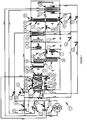
- an incoming air treatment unit in a room is shown, indicated overall with the reference number 1.
- the treatment unit 1 comprises an aeraulic circuit linked with at least one first cooling circuit with a reversible summer/winter direct expansion operating cycle.
- the treatment unit 1 has a single-block construction that provides a casing inside which all the components that are part of the cooling circuits provided and the aeraulic circuit are integrated.
- the aeraulic circuit is also linked with at least a second cooling circuit with a reversible summer/winter direct expansion operating cycle, separate from the first cooling circuit.
- the a (2015)lic circuit comprises an air supply channel 2 into the room, an air return channel 3 from the room, at least one supply fan 4 provided along the supply channel 2 for the generation of an air flow, preferably a return fan 5 provided along the return channel 3, at least one desiccant rotor 6 impregnated with a dehydrating and adsorbent material, and a rotary enthalpy recuperator 7 acting as a heat exchanger between the supply channel 2 and the return channel 3.
- the rotary heat recuperator 7 is controlled by a speed regulator, for example, an inverter.
- the rotary recuperator 7 has the task of exchanging sensitive and latent heat between the supply air and the return air.
- the supply fan 4 is also controlled by a speed regulator, and in particular the return fan 5 is also controlled by a speed regulator.
- fans 4 and 5 are plug fans with an asynchronous motor controlled by an inverter.
- the desiccant rotor 6 is preferably constructed with flat and corrugated sheets whose surface is coated with a layer of silica gel whose ability to withhold and release humidity varies as the temperature of the air flow that hits it varies.
- the desiccant rotor 6 intercepts the supply channel 2 in correspondence with a first point and in correspondence with a second point downstream of the first point with respect to the supply air flow.
- a first heat exchanger 8 is provided between the supply channel 2 of the aunterlic circuit and the first cooling circuit
- a second heat exchanger 9 is provided between the supply channel 2 of the a Vogellic circuit and the first cooling circuit
- a third heat exchanger 10 is provided between an end compartment 27 of the return channel 3 of the a6.3lic circuit and the first cooling circuit.
- a fourth heat exchanger 11 is provided between the supply channel 2 of the aunterlic circuit and the second cooling circuit
- a fifth heat exchanger 12 is provided between the supply channel 2 of the a Vogellic circuit and the second cooling circuit
- a sixth heat exchanger 13 is provided between the end compartment 27 of the return channel 3 of the a6.3lic circuit and the second cooling circuit.
- the fourth heat exchanger 11 and the first heat exchanger 8 comprise mutually engaged finned batteries, just as the fifth heat exchanger 12 and the second heat exchanger 9 comprise mutually engaged finned batteries.
- the third heat exchanger 10 and the sixth heat exchanger 13 each comprise a finned battery to which one or more axial fans 10a, 13a are connected.
- compartment 27 is split into two adjacent independent sub-compartments 28,29 through a dividing wall 30.
- the sub-compartment 28, where the finned pack 10 and the axial fan 10a are positioned, has a first access route 31 equipped with first gate valve means 32 for sucking the air from the external environment, a second access route 33 equipped with gate valve means 34 for accessing the air flow from the return channel 3, and an exit route 35 for the return air flow.
- the sub-compartment 29, where the finned pack 13 and the axial fan 13a are positioned, has a first access route 36 equipped with first gate valve means 37 for sucking the air from the external environment, a second access route 38 equipped with gate valve means 39 for accessing the air flow from the return channel 3, and an exit route 40 for the return air flow.
- the a somehowlic circuit preferably comprises, between a supply channel 2 downstream of the heat recuperator 7 with respect to the supply air flow and a point of the return channel 3 upstream of the heat recuperator 7 with respect to the return air flow, a connection channel 14a equipped with valve means, for example gate valve means 14 for bypassing the heat recuperator 7.
- the aeraulic circuit preferably also comprises a derivation 15 of the supply channel 2 in a point of the supply channel 2 upstream of the first point in which the desiccant rotor 6 intercepts the supply air flow, equipped with valve means 16, for example gate valve means, for bypassing the dessicant rotor 6.
- the a somehowlic circuit further comprises splitting means 17 of the supply air flow rate crossing the desiccant rotor 6.
- the splitting means 17 comprise a derivation 18 of the supply channel 2 equipped with valve means 19.
- a derivation 18 originates in a point of the supply channel 2 upstream of the first point in which the desiccant rotor 6 intercepts the supply air flow, and terminates in a point of the supply channel 2 downstream of the first point in which the desiccant rotor 6 intercepts the supply air flow but upstream of the set formed by the second heat exchanger 9 and the fifth heat exchanger 12.
- the splitting means 17 further comprise a derivation 20 of the supply channel 2 equipped with valve means 21.
- a derivation 20 originates in a point of the supply channel 2 upstream of the second point in which the desiccant rotor 6 intercepts the supply air flow but downstream of the set formed by the second heat exchanger 9 and the fifth heat exchanger 12, and terminates in a point of the supply channel 2 downstream of the second point in which the desiccant rotor 6 intercepts the supply air flow.
- the supply channel 2 there is a succession in cascade of the heat recuperator 7, the supply fan 4, the set formed by the first heat exchanger 8 and the fourth heat exchanger 11, a first angular sector of the desiccant rotor 6, the set formed by the second heat exchanger 9 and the fifth heat exchanger 12, and a second angular sector of the desiccant rotor 6 diametrically opposite the first angular sector.
- the a Vogellic circuit is completed by a terminal 47 for the incoming air to be treated in the supply channel 2, equipped with special rainproof grille 48, pleated filters 49, 50 for the incoming air to the rotary recuperator 7, and high efficiency filters 51.
- the first cooling circuit further to the first heat exchanger 8, the second heat exchanger 9 and the third heat exchanger 10 comprises at least one compressor 22 controlled by a speed regulator, for example, an inverter, a four-way valve 41 for inverting the cycle, an expansion valve 42, valve means 52,53,54,55,56,57 and modulating valve means 43 of the supply of the second heat exchanger 8.
- a speed regulator for example, an inverter, a four-way valve 41 for inverting the cycle, an expansion valve 42, valve means 52,53,54,55,56,57 and modulating valve means 43 of the supply of the second heat exchanger 8.
- the second cooling circuit further comprises as well as the fourth heat exchanger 11, the fifth heat exchanger 12 and the sixth heat exchanger 13, at least one fixed speed compressor 23, a four-way valve 44 for inverting the cycle, an expansion valve 45, and valve means 46 for modulating the supply to the fourth heat exchanger 11.
- the first exchanger 8 when the first cooling circuit is active, can act as a condenser for the first cooling circuit for heating the air flow circulating in the supply channel 2 when the regeneration of the desiccant rotor 6 is requested, the second heat exchanger 9 acts as an evaporator for the first cooling circuit for cooling (alone or potentially in combination with the evaporator of the second cooling circuit) the air flow circulating in the supply channel 2 to the desired temperature, the desiccant rotor 6 interacts with the air flow heated by the first heat exchanger 8 when the regeneration process is active, and with the air flow cooled by the second heat exchanger 9 to dehumidify it, while the third heat exchanger 10 acts as a condenser for the first cooling circuit.
- the fourth exchanger 11 can act as a condenser for the second cooling circuit for heating the air flow circulating in the supply channel 2 when the regeneration of the desiccant rotor 6 is requested
- the fifth heat exchanger 12 acts as an evaporator for the second cooling circuit for cooling the air flow circulating in the supply channel 2 to the desired temperature (alone or potentially in combination with the evaporator of the first cooling circuit)
- the desiccant rotor 6 interacts with the air flow heated by the fourth heat exchanger 11 to regenerate the dehydrating and adsorbent material when the regeneration process is active, and with the air flow cooled by the fifth heat exchanger 12 to dehumidify it
- the sixth heat exchanger 13 acts as a condenser for the second cooling circuit.
- the incoming air to the batteries 10 and/or 13 is made up of a mixture of the external air that enters from the gates 32 and/or 37, and the return air arriving from the gates 34 and/or 39.
- the axial fans 10a, 13a have a variable speed and their air flow rate is a function of the condensation pressure.
- the return air flow rate transiting from the gates 32 and/or 37 is constant since the flow rate of the supply air flow is constant.
- the incoming mixture to the batteries 10 and/or 13 is comprised of an air flow with a variable air flow rate and temperature.
- the energy content of the return air flow is also used by activating the rotary heat recuperator 7 and at least a part of the condensing power of the second heat exchanger 8 of the first cooling circuit and/or the fourth heat exchanger 11 of the second cooling circuit is used, if provided, for the regeneration of the desiccant rotor 6.
- the temperature is controlled thanks to the variable speed compressor 22 and the supply and return fans 4 and 5, which guarantee the required supply and return air flow rates from the room necessary to guarantee the enthalpy jump required on the rotary recuperator 7 whose speed is regulated in turn in order to appropriately regulate in combination with the variable speed compressor 22 the enthalpy content to be transferred to the treatment air.
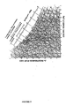
- the supply air is subject to the following transformations: 1-2 through the heat recuperator 7; 2-3 through the regenerating section of the desiccant rotor 6; 3-4 through the second heat exchanger 9; and 4-5 through the process section of the desiccant rotor 6.
- the dehumidification of the air to be treated is performed through the desiccant rotor 6.
- This actuates an air drying process using a consistent amount of silica gel deposited on a drum comprising a light, heat-insulating material in order to transfer only the latent heat part.
- the flow rate of the supply air flow regulated which crosses the desiccant rotor 6 according to the specific humidity contained in the supply air before interaction with the desiccant rotor 6 itself.
- the gate valve means 19 and 21 open completely to by-pass the desiccant rotor 6, and if the specific humidity in the air to be treated is very high, the gate valve means 19 and 21 shut completely in order to have the maximum dehumidification effect possible by the desiccant rotor 6. According to the specific humidity of the air to be treated, measured by an appropriate humidity probe, it is possible to regulate the opening of the gate means 19 and 21.
- the gate valve means 19 and 21 When in the summer operating cycle the gate valve means 19 and 21 are completely closed, if the desiccant rotor 6 is not able to absorb humidity, it is necessary to implement its regeneration which preferably but not necessarily happens through the first cooling circuit alone.
- the regeneration takes place as seen through heating by the first heat exchanger 8 which operates with part of the hot gas from the compressor 22.
- the modulating valve means 43 may be adjusted at the opening in order to supply the first heat exchanger 8 with the coolant gas, with the purpose of drying the desiccant rotor 6 by the amount necessary to reduce the water content in the air.
- the first heat exchanger 8 and the fourth heat exchanger 11 act as condensers, whereas the third heat exchanger 10 and the sixth heat exchanger 13 act as evaporators.
- the treatment unit 1 can operate on full load, that is, with just one of the two cooling circuits active, or in partial load mode, with just one of the two cooling circuits active.
- the return air transits through the gates 34 and 39 and is conveyed into the top of the finned batteries 10, 13 to then be expelled through the axial fans 10a, 13a.
- the return air is conveyed below the finned battery 10 to then be expelled through the axial fans 10a if the first cooling circuit is active, or is conveyed below the finned battery 13 to then be expelled through the axial fans 13a if the second cooling circuit is active.
- the treatment unit 1 can operate in a complete supply air recirculation capacity in which the rotary recuperator 7 is by-passed.
- the treatment unit 1 In the winter operating cycle the treatment unit 1 only uses the return air for evaporation on the batteries 10 and/or 13. In fact the gates 32 and 37 are closed and the air that crosses the batteries 10 and/or 13 is only the return air that transits through the recuperator 7, whereas the axial fans 10a, 13a in this case have a minimum rotation speed so as to counterbalance the load loss of the batteries 10, 13 in order to equalise the internal pressure of the relative compartments 28, 29 to atmospheric pressure. In partial load operating mode, the axial fans 10a, 13a relative to the cooling circuit that is not working, are off.
- the treatment unit 1 as conceived herein is susceptible to many modifications and variations, all falling within the scope of the invented concept as disclosed by the appended claims; furthermore, all the details are replaceable by technically equivalent elements.
- the materials used, as well as the dimensions, may in practice be of any type according to requirements and the state of the art.
Landscapes
- Engineering & Computer Science (AREA)
- Mechanical Engineering (AREA)
- General Engineering & Computer Science (AREA)
- Chemical & Material Sciences (AREA)
- Combustion & Propulsion (AREA)
- Life Sciences & Earth Sciences (AREA)
- Sustainable Development (AREA)
- Physics & Mathematics (AREA)
- Thermal Sciences (AREA)
- Central Air Conditioning (AREA)
- Drying Of Gases (AREA)
- Devices For Use In Laboratory Experiments (AREA)
Applications Claiming Priority (1)
| Application Number | Priority Date | Filing Date | Title |
|---|---|---|---|
| IT002084A ITMI20122084A1 (it) | 2012-12-06 | 2012-12-06 | Unita' di trattamento dell¿aria in ingresso in un ambiente |
Publications (2)
| Publication Number | Publication Date |
|---|---|
| EP2741018A1 EP2741018A1 (en) | 2014-06-11 |
| EP2741018B1 true EP2741018B1 (en) | 2019-02-20 |
Family
ID=47605636
Family Applications (1)
| Application Number | Title | Priority Date | Filing Date |
|---|---|---|---|
| EP13194785.5A Active EP2741018B1 (en) | 2012-12-06 | 2013-11-28 | Treatment unit of the incoming air to a room |
Country Status (2)
| Country | Link |
|---|---|
| EP (1) | EP2741018B1 (it) |
| IT (1) | ITMI20122084A1 (it) |
Families Citing this family (3)
| Publication number | Priority date | Publication date | Assignee | Title |
|---|---|---|---|---|
| JP7078375B2 (ja) * | 2017-10-05 | 2022-05-31 | 高砂熱学工業株式会社 | デシカントロータを用いた外気処理機及び外気処理方法 |
| RU2708419C1 (ru) * | 2019-06-20 | 2019-12-06 | Владимир Евгеньевич Воскресенский | Система кондиционирования приточного воздуха с безжидкостным роторным нагреванием |
| IT202300012144A1 (it) * | 2023-06-13 | 2024-12-13 | Nuova S B System S R L | Macchina lavaendoscopi con sistema di asciugatura dei canali interni di endoscopi ricondizionati |
Family Cites Families (6)
| Publication number | Priority date | Publication date | Assignee | Title |
|---|---|---|---|---|
| US4887438A (en) * | 1989-02-27 | 1989-12-19 | Milton Meckler | Desiccant assisted air conditioner |
| JP2968232B2 (ja) * | 1997-04-11 | 1999-10-25 | 株式会社荏原製作所 | 空調システム及びその運転方法 |
| JP2968241B2 (ja) * | 1997-10-24 | 1999-10-25 | 株式会社荏原製作所 | 除湿空調システム及びその運転方法 |
| US6141979A (en) * | 1999-11-19 | 2000-11-07 | American Standard Inc. | Dual heat exchanger wheels with variable speed |
| JP2002061894A (ja) * | 2000-08-22 | 2002-02-28 | Seibu Giken Co Ltd | 除湿空調装置 |
| US6711907B2 (en) * | 2001-02-28 | 2004-03-30 | Munters Corporation | Desiccant refrigerant dehumidifier systems |
-
2012
- 2012-12-06 IT IT002084A patent/ITMI20122084A1/it unknown
-
2013
- 2013-11-28 EP EP13194785.5A patent/EP2741018B1/en active Active
Non-Patent Citations (1)
| Title |
|---|
| None * |
Also Published As
| Publication number | Publication date |
|---|---|
| ITMI20122084A1 (it) | 2014-06-07 |
| EP2741018A1 (en) | 2014-06-11 |
Similar Documents
| Publication | Publication Date | Title |
|---|---|---|
| CA2707793C (en) | Energy recovery enhanced condenser reactivated desiccant refrigerant dehumidifier | |
| CA2969999C (en) | AIR CONDITIONING SYSTEM EQUIPPED WITH A PASSIVE DEHUMIDIFICATION WHEEL, RECOVERY WHEEL, COOLING COOLER AND SECONDARY DIRECT EXPANSION CIRCUIT | |
| US9885486B2 (en) | Heat pump humidifier and dehumidifier system and method | |
| US11525600B2 (en) | Air conditioning system and control method thereof | |
| AU2013354898B2 (en) | Compact desiccant cooling system | |
| CN104633837B (zh) | 空调器的除湿控制方法 | |
| JP5669587B2 (ja) | 低温再生デシカント空調機および運転方法 | |
| WO2004055443A1 (en) | Desiccant refrigerant dehumidifier systems | |
| AU2012262681A1 (en) | Compact desiccant cooling system | |
| JP5542701B2 (ja) | 低温再生デシカント空調機 | |
| US10274210B2 (en) | Heat pump humidifier and dehumidifier system and method | |
| CN105423457B (zh) | 空调系统 | |
| EP2741018B1 (en) | Treatment unit of the incoming air to a room | |
| EP3136022B1 (en) | Hybrid heat pump apparatus | |
| JP6532270B2 (ja) | 低温再生デシカント空調機 | |
| KR20150041997A (ko) | 선박건조중 내부 습도조절을 위한 다목적 제습장치 | |
| EP3133352B1 (en) | Dehumidifying and cooling apparatus | |
| JP7129281B2 (ja) | デシカント空調機 | |
| JP5714946B2 (ja) | 空調システム | |
| CN216281786U (zh) | 一种带热泵功能的调温除湿机 | |
| JPH06101930A (ja) | 吸湿剤を用いた空気冷却装置 | |
| Bellemo et al. | Modelling and analysis of a desiccant cooling system using the regenerative indirect evaporative cooling process | |
| CN115493253B (zh) | 用于调湿装置的控制方法、控制装置及调湿装置 | |
| JPS5950897B2 (ja) | 省エネルギ−型冷房空調装置 |
Legal Events
| Date | Code | Title | Description |
|---|---|---|---|
| PUAI | Public reference made under article 153(3) epc to a published international application that has entered the european phase |
Free format text: ORIGINAL CODE: 0009012 |
|
| 17P | Request for examination filed |
Effective date: 20131128 |
|
| AK | Designated contracting states |
Kind code of ref document: A1 Designated state(s): AL AT BE BG CH CY CZ DE DK EE ES FI FR GB GR HR HU IE IS IT LI LT LU LV MC MK MT NL NO PL PT RO RS SE SI SK SM TR |
|
| AX | Request for extension of the european patent |
Extension state: BA ME |
|
| R17P | Request for examination filed (corrected) |
Effective date: 20140807 |
|
| RBV | Designated contracting states (corrected) |
Designated state(s): AL AT BE BG CH CY CZ DE DK EE ES FI FR GB GR HR HU IE IS IT LI LT LU LV MC MK MT NL NO PL PT RO RS SE SI SK SM TR |
|
| RAP1 | Party data changed (applicant data changed or rights of an application transferred) |
Owner name: MITSUBISHI ELECTRIC HYDRONICS & IT COOLING SYSTEMS |
|
| GRAP | Despatch of communication of intention to grant a patent |
Free format text: ORIGINAL CODE: EPIDOSNIGR1 |
|
| STAA | Information on the status of an ep patent application or granted ep patent |
Free format text: STATUS: GRANT OF PATENT IS INTENDED |
|
| INTG | Intention to grant announced |
Effective date: 20180928 |
|
| GRAS | Grant fee paid |
Free format text: ORIGINAL CODE: EPIDOSNIGR3 |
|
| GRAA | (expected) grant |
Free format text: ORIGINAL CODE: 0009210 |
|
| STAA | Information on the status of an ep patent application or granted ep patent |
Free format text: STATUS: THE PATENT HAS BEEN GRANTED |
|
| AK | Designated contracting states |
Kind code of ref document: B1 Designated state(s): AL AT BE BG CH CY CZ DE DK EE ES FI FR GB GR HR HU IE IS IT LI LT LU LV MC MK MT NL NO PL PT RO RS SE SI SK SM TR |
|
| REG | Reference to a national code |
Ref country code: GB Ref legal event code: FG4D |
|
| REG | Reference to a national code |
Ref country code: CH Ref legal event code: EP |
|
| REG | Reference to a national code |
Ref country code: DE Ref legal event code: R096 Ref document number: 602013050941 Country of ref document: DE |
|
| REG | Reference to a national code |
Ref country code: AT Ref legal event code: REF Ref document number: 1098708 Country of ref document: AT Kind code of ref document: T Effective date: 20190315 |
|
| REG | Reference to a national code |
Ref country code: IE Ref legal event code: FG4D |
|
| REG | Reference to a national code |
Ref country code: NL Ref legal event code: MP Effective date: 20190220 |
|
| REG | Reference to a national code |
Ref country code: LT Ref legal event code: MG4D |
|
| PG25 | Lapsed in a contracting state [announced via postgrant information from national office to epo] |
Ref country code: PT Free format text: LAPSE BECAUSE OF FAILURE TO SUBMIT A TRANSLATION OF THE DESCRIPTION OR TO PAY THE FEE WITHIN THE PRESCRIBED TIME-LIMIT Effective date: 20190620 Ref country code: FI Free format text: LAPSE BECAUSE OF FAILURE TO SUBMIT A TRANSLATION OF THE DESCRIPTION OR TO PAY THE FEE WITHIN THE PRESCRIBED TIME-LIMIT Effective date: 20190220 Ref country code: NL Free format text: LAPSE BECAUSE OF FAILURE TO SUBMIT A TRANSLATION OF THE DESCRIPTION OR TO PAY THE FEE WITHIN THE PRESCRIBED TIME-LIMIT Effective date: 20190220 Ref country code: LT Free format text: LAPSE BECAUSE OF FAILURE TO SUBMIT A TRANSLATION OF THE DESCRIPTION OR TO PAY THE FEE WITHIN THE PRESCRIBED TIME-LIMIT Effective date: 20190220 Ref country code: SE Free format text: LAPSE BECAUSE OF FAILURE TO SUBMIT A TRANSLATION OF THE DESCRIPTION OR TO PAY THE FEE WITHIN THE PRESCRIBED TIME-LIMIT Effective date: 20190220 Ref country code: NO Free format text: LAPSE BECAUSE OF FAILURE TO SUBMIT A TRANSLATION OF THE DESCRIPTION OR TO PAY THE FEE WITHIN THE PRESCRIBED TIME-LIMIT Effective date: 20190520 |
|
| REG | Reference to a national code |
Ref country code: DE Ref legal event code: R082 Ref document number: 602013050941 Country of ref document: DE Representative=s name: HANNKE BITTNER & PARTNER, PATENT- UND RECHTSAN, DE Ref country code: DE Ref legal event code: R081 Ref document number: 602013050941 Country of ref document: DE Owner name: MITSUBISHI ELECTRIC HYDRONICS & IT COOLING SYS, IT Free format text: FORMER OWNER: MITSUBISHI ELECTRIC HYDRONICS & IT COOLING SYSTEMS S.P.A., TREVISO, IT |
|
| RAP2 | Party data changed (patent owner data changed or rights of a patent transferred) |
Owner name: MITSUBISHI ELECTRIC HYDRONICS & IT COOLING SYSTEMS |
|
| PG25 | Lapsed in a contracting state [announced via postgrant information from national office to epo] |
Ref country code: HR Free format text: LAPSE BECAUSE OF FAILURE TO SUBMIT A TRANSLATION OF THE DESCRIPTION OR TO PAY THE FEE WITHIN THE PRESCRIBED TIME-LIMIT Effective date: 20190220 Ref country code: RS Free format text: LAPSE BECAUSE OF FAILURE TO SUBMIT A TRANSLATION OF THE DESCRIPTION OR TO PAY THE FEE WITHIN THE PRESCRIBED TIME-LIMIT Effective date: 20190220 Ref country code: LV Free format text: LAPSE BECAUSE OF FAILURE TO SUBMIT A TRANSLATION OF THE DESCRIPTION OR TO PAY THE FEE WITHIN THE PRESCRIBED TIME-LIMIT Effective date: 20190220 Ref country code: GR Free format text: LAPSE BECAUSE OF FAILURE TO SUBMIT A TRANSLATION OF THE DESCRIPTION OR TO PAY THE FEE WITHIN THE PRESCRIBED TIME-LIMIT Effective date: 20190521 Ref country code: IS Free format text: LAPSE BECAUSE OF FAILURE TO SUBMIT A TRANSLATION OF THE DESCRIPTION OR TO PAY THE FEE WITHIN THE PRESCRIBED TIME-LIMIT Effective date: 20190620 Ref country code: BG Free format text: LAPSE BECAUSE OF FAILURE TO SUBMIT A TRANSLATION OF THE DESCRIPTION OR TO PAY THE FEE WITHIN THE PRESCRIBED TIME-LIMIT Effective date: 20190520 |
|
| REG | Reference to a national code |
Ref country code: AT Ref legal event code: MK05 Ref document number: 1098708 Country of ref document: AT Kind code of ref document: T Effective date: 20190220 |
|
| PG25 | Lapsed in a contracting state [announced via postgrant information from national office to epo] |
Ref country code: EE Free format text: LAPSE BECAUSE OF FAILURE TO SUBMIT A TRANSLATION OF THE DESCRIPTION OR TO PAY THE FEE WITHIN THE PRESCRIBED TIME-LIMIT Effective date: 20190220 Ref country code: CZ Free format text: LAPSE BECAUSE OF FAILURE TO SUBMIT A TRANSLATION OF THE DESCRIPTION OR TO PAY THE FEE WITHIN THE PRESCRIBED TIME-LIMIT Effective date: 20190220 Ref country code: RO Free format text: LAPSE BECAUSE OF FAILURE TO SUBMIT A TRANSLATION OF THE DESCRIPTION OR TO PAY THE FEE WITHIN THE PRESCRIBED TIME-LIMIT Effective date: 20190220 Ref country code: AL Free format text: LAPSE BECAUSE OF FAILURE TO SUBMIT A TRANSLATION OF THE DESCRIPTION OR TO PAY THE FEE WITHIN THE PRESCRIBED TIME-LIMIT Effective date: 20190220 Ref country code: ES Free format text: LAPSE BECAUSE OF FAILURE TO SUBMIT A TRANSLATION OF THE DESCRIPTION OR TO PAY THE FEE WITHIN THE PRESCRIBED TIME-LIMIT Effective date: 20190220 Ref country code: DK Free format text: LAPSE BECAUSE OF FAILURE TO SUBMIT A TRANSLATION OF THE DESCRIPTION OR TO PAY THE FEE WITHIN THE PRESCRIBED TIME-LIMIT Effective date: 20190220 Ref country code: SK Free format text: LAPSE BECAUSE OF FAILURE TO SUBMIT A TRANSLATION OF THE DESCRIPTION OR TO PAY THE FEE WITHIN THE PRESCRIBED TIME-LIMIT Effective date: 20190220 |
|
| REG | Reference to a national code |
Ref country code: DE Ref legal event code: R097 Ref document number: 602013050941 Country of ref document: DE |
|
| PG25 | Lapsed in a contracting state [announced via postgrant information from national office to epo] |
Ref country code: PL Free format text: LAPSE BECAUSE OF FAILURE TO SUBMIT A TRANSLATION OF THE DESCRIPTION OR TO PAY THE FEE WITHIN THE PRESCRIBED TIME-LIMIT Effective date: 20190220 Ref country code: SM Free format text: LAPSE BECAUSE OF FAILURE TO SUBMIT A TRANSLATION OF THE DESCRIPTION OR TO PAY THE FEE WITHIN THE PRESCRIBED TIME-LIMIT Effective date: 20190220 |
|
| PLBE | No opposition filed within time limit |
Free format text: ORIGINAL CODE: 0009261 |
|
| STAA | Information on the status of an ep patent application or granted ep patent |
Free format text: STATUS: NO OPPOSITION FILED WITHIN TIME LIMIT |
|
| PG25 | Lapsed in a contracting state [announced via postgrant information from national office to epo] |
Ref country code: AT Free format text: LAPSE BECAUSE OF FAILURE TO SUBMIT A TRANSLATION OF THE DESCRIPTION OR TO PAY THE FEE WITHIN THE PRESCRIBED TIME-LIMIT Effective date: 20190220 |
|
| 26N | No opposition filed |
Effective date: 20191121 |
|
| PG25 | Lapsed in a contracting state [announced via postgrant information from national office to epo] |
Ref country code: SI Free format text: LAPSE BECAUSE OF FAILURE TO SUBMIT A TRANSLATION OF THE DESCRIPTION OR TO PAY THE FEE WITHIN THE PRESCRIBED TIME-LIMIT Effective date: 20190220 |
|
| PG25 | Lapsed in a contracting state [announced via postgrant information from national office to epo] |
Ref country code: TR Free format text: LAPSE BECAUSE OF FAILURE TO SUBMIT A TRANSLATION OF THE DESCRIPTION OR TO PAY THE FEE WITHIN THE PRESCRIBED TIME-LIMIT Effective date: 20190220 |
|
| REG | Reference to a national code |
Ref country code: CH Ref legal event code: PL |
|
| PG25 | Lapsed in a contracting state [announced via postgrant information from national office to epo] |
Ref country code: LU Free format text: LAPSE BECAUSE OF NON-PAYMENT OF DUE FEES Effective date: 20191128 Ref country code: MC Free format text: LAPSE BECAUSE OF FAILURE TO SUBMIT A TRANSLATION OF THE DESCRIPTION OR TO PAY THE FEE WITHIN THE PRESCRIBED TIME-LIMIT Effective date: 20190220 Ref country code: LI Free format text: LAPSE BECAUSE OF NON-PAYMENT OF DUE FEES Effective date: 20191130 Ref country code: CH Free format text: LAPSE BECAUSE OF NON-PAYMENT OF DUE FEES Effective date: 20191130 |
|
| REG | Reference to a national code |
Ref country code: BE Ref legal event code: MM Effective date: 20191130 |
|
| PG25 | Lapsed in a contracting state [announced via postgrant information from national office to epo] |
Ref country code: IE Free format text: LAPSE BECAUSE OF NON-PAYMENT OF DUE FEES Effective date: 20191128 |
|
| PG25 | Lapsed in a contracting state [announced via postgrant information from national office to epo] |
Ref country code: BE Free format text: LAPSE BECAUSE OF NON-PAYMENT OF DUE FEES Effective date: 20191130 |
|
| PG25 | Lapsed in a contracting state [announced via postgrant information from national office to epo] |
Ref country code: CY Free format text: LAPSE BECAUSE OF FAILURE TO SUBMIT A TRANSLATION OF THE DESCRIPTION OR TO PAY THE FEE WITHIN THE PRESCRIBED TIME-LIMIT Effective date: 20190220 |
|
| PG25 | Lapsed in a contracting state [announced via postgrant information from national office to epo] |
Ref country code: HU Free format text: LAPSE BECAUSE OF FAILURE TO SUBMIT A TRANSLATION OF THE DESCRIPTION OR TO PAY THE FEE WITHIN THE PRESCRIBED TIME-LIMIT; INVALID AB INITIO Effective date: 20131128 Ref country code: MT Free format text: LAPSE BECAUSE OF FAILURE TO SUBMIT A TRANSLATION OF THE DESCRIPTION OR TO PAY THE FEE WITHIN THE PRESCRIBED TIME-LIMIT Effective date: 20190220 |
|
| PG25 | Lapsed in a contracting state [announced via postgrant information from national office to epo] |
Ref country code: MK Free format text: LAPSE BECAUSE OF FAILURE TO SUBMIT A TRANSLATION OF THE DESCRIPTION OR TO PAY THE FEE WITHIN THE PRESCRIBED TIME-LIMIT Effective date: 20190220 |
|
| P01 | Opt-out of the competence of the unified patent court (upc) registered |
Effective date: 20230524 |
|
| PGFP | Annual fee paid to national office [announced via postgrant information from national office to epo] |
Ref country code: DE Payment date: 20251126 Year of fee payment: 13 |
|
| PGFP | Annual fee paid to national office [announced via postgrant information from national office to epo] |
Ref country code: GB Payment date: 20251020 Year of fee payment: 13 |
|
| PGFP | Annual fee paid to national office [announced via postgrant information from national office to epo] |
Ref country code: IT Payment date: 20251030 Year of fee payment: 13 |
|
| PGFP | Annual fee paid to national office [announced via postgrant information from national office to epo] |
Ref country code: FR Payment date: 20251124 Year of fee payment: 13 |