EP2739913B2 - Einbauprofil - Google Patents
Einbauprofil Download PDFInfo
- Publication number
- EP2739913B2 EP2739913B2 EP12734929.8A EP12734929A EP2739913B2 EP 2739913 B2 EP2739913 B2 EP 2739913B2 EP 12734929 A EP12734929 A EP 12734929A EP 2739913 B2 EP2739913 B2 EP 2739913B2
- Authority
- EP
- European Patent Office
- Prior art keywords
- heat exchanger
- profile
- recessed profile
- flow
- exchanger material
- Prior art date
- Legal status (The legal status is an assumption and is not a legal conclusion. Google has not performed a legal analysis and makes no representation as to the accuracy of the status listed.)
- Active
Links
Images


Classifications
-
- F—MECHANICAL ENGINEERING; LIGHTING; HEATING; WEAPONS; BLASTING
- F24—HEATING; RANGES; VENTILATING
- F24F—AIR-CONDITIONING; AIR-HUMIDIFICATION; VENTILATION; USE OF AIR CURRENTS FOR SCREENING
- F24F7/00—Ventilation
- F24F7/04—Ventilation with ducting systems, e.g. by double walls; with natural circulation
- F24F7/06—Ventilation with ducting systems, e.g. by double walls; with natural circulation with forced air circulation, e.g. by fan positioning of a ventilator in or against a conduit
- F24F7/08—Ventilation with ducting systems, e.g. by double walls; with natural circulation with forced air circulation, e.g. by fan positioning of a ventilator in or against a conduit with separate ducts for supplied and exhausted air with provisions for reversal of the input and output systems
-
- C—CHEMISTRY; METALLURGY
- C02—TREATMENT OF WATER, WASTE WATER, SEWAGE, OR SLUDGE
- C02F—TREATMENT OF WATER, WASTE WATER, SEWAGE, OR SLUDGE
- C02F1/00—Treatment of water, waste water, or sewage
- C02F1/46—Treatment of water, waste water, or sewage by electrochemical methods
- C02F1/461—Treatment of water, waste water, or sewage by electrochemical methods by electrolysis
- C02F1/467—Treatment of water, waste water, or sewage by electrochemical methods by electrolysis by electrochemical disinfection; by electrooxydation or by electroreduction
- C02F1/4672—Treatment of water, waste water, or sewage by electrochemical methods by electrolysis by electrochemical disinfection; by electrooxydation or by electroreduction by electrooxydation
-
- E—FIXED CONSTRUCTIONS
- E03—WATER SUPPLY; SEWERAGE
- E03C—DOMESTIC PLUMBING INSTALLATIONS FOR FRESH WATER OR WASTE WATER; SINKS
- E03C1/00—Domestic plumbing installations for fresh water or waste water; Sinks
- E03C1/02—Plumbing installations for fresh water
- E03C1/10—Devices for preventing contamination of drinking-water pipes, e.g. means for aerating self-closing flushing valves
- E03C1/106—Devices for preventing contamination of drinking-water pipes, e.g. means for aerating self-closing flushing valves using two or more check valves
-
- E—FIXED CONSTRUCTIONS
- E06—DOORS, WINDOWS, SHUTTERS, OR ROLLER BLINDS IN GENERAL; LADDERS
- E06B—FIXED OR MOVABLE CLOSURES FOR OPENINGS IN BUILDINGS, VEHICLES, FENCES OR LIKE ENCLOSURES IN GENERAL, e.g. DOORS, WINDOWS, BLINDS, GATES
- E06B7/00—Special arrangements or measures in connection with doors or windows
- E06B7/02—Special arrangements or measures in connection with doors or windows for providing ventilation, e.g. through double windows; Arrangement of ventilation roses
- E06B7/10—Special arrangements or measures in connection with doors or windows for providing ventilation, e.g. through double windows; Arrangement of ventilation roses by special construction of the frame members
-
- F—MECHANICAL ENGINEERING; LIGHTING; HEATING; WEAPONS; BLASTING
- F24—HEATING; RANGES; VENTILATING
- F24F—AIR-CONDITIONING; AIR-HUMIDIFICATION; VENTILATION; USE OF AIR CURRENTS FOR SCREENING
- F24F12/00—Use of energy recovery systems in air conditioning, ventilation or screening
- F24F12/001—Use of energy recovery systems in air conditioning, ventilation or screening with heat-exchange between supplied and exhausted air
- F24F12/002—Use of energy recovery systems in air conditioning, ventilation or screening with heat-exchange between supplied and exhausted air using an intermediate heat-transfer fluid
-
- F—MECHANICAL ENGINEERING; LIGHTING; HEATING; WEAPONS; BLASTING
- F24—HEATING; RANGES; VENTILATING
- F24F—AIR-CONDITIONING; AIR-HUMIDIFICATION; VENTILATION; USE OF AIR CURRENTS FOR SCREENING
- F24F12/00—Use of energy recovery systems in air conditioning, ventilation or screening
- F24F12/001—Use of energy recovery systems in air conditioning, ventilation or screening with heat-exchange between supplied and exhausted air
- F24F12/006—Use of energy recovery systems in air conditioning, ventilation or screening with heat-exchange between supplied and exhausted air using an air-to-air heat exchanger
-
- F—MECHANICAL ENGINEERING; LIGHTING; HEATING; WEAPONS; BLASTING
- F24—HEATING; RANGES; VENTILATING
- F24F—AIR-CONDITIONING; AIR-HUMIDIFICATION; VENTILATION; USE OF AIR CURRENTS FOR SCREENING
- F24F13/00—Details common to, or for air-conditioning, air-humidification, ventilation or use of air currents for screening
- F24F13/08—Air-flow control members, e.g. louvres, grilles, flaps or guide plates
- F24F13/18—Air-flow control members, e.g. louvres, grilles, flaps or guide plates specially adapted for insertion in flat panels, e.g. in door or window-pane
-
- F—MECHANICAL ENGINEERING; LIGHTING; HEATING; WEAPONS; BLASTING
- F24—HEATING; RANGES; VENTILATING
- F24F—AIR-CONDITIONING; AIR-HUMIDIFICATION; VENTILATION; USE OF AIR CURRENTS FOR SCREENING
- F24F13/00—Details common to, or for air-conditioning, air-humidification, ventilation or use of air currents for screening
- F24F13/30—Arrangement or mounting of heat-exchangers
-
- F—MECHANICAL ENGINEERING; LIGHTING; HEATING; WEAPONS; BLASTING
- F24—HEATING; RANGES; VENTILATING
- F24F—AIR-CONDITIONING; AIR-HUMIDIFICATION; VENTILATION; USE OF AIR CURRENTS FOR SCREENING
- F24F5/00—Air-conditioning systems or apparatus not covered by F24F1/00 or F24F3/00, e.g. using solar heat or combined with household units such as an oven or water heater
- F24F5/0007—Air-conditioning systems or apparatus not covered by F24F1/00 or F24F3/00, e.g. using solar heat or combined with household units such as an oven or water heater cooling apparatus specially adapted for use in air-conditioning
- F24F5/0017—Air-conditioning systems or apparatus not covered by F24F1/00 or F24F3/00, e.g. using solar heat or combined with household units such as an oven or water heater cooling apparatus specially adapted for use in air-conditioning using cold storage bodies, e.g. ice
-
- F—MECHANICAL ENGINEERING; LIGHTING; HEATING; WEAPONS; BLASTING
- F24—HEATING; RANGES; VENTILATING
- F24F—AIR-CONDITIONING; AIR-HUMIDIFICATION; VENTILATION; USE OF AIR CURRENTS FOR SCREENING
- F24F7/00—Ventilation
- F24F7/04—Ventilation with ducting systems, e.g. by double walls; with natural circulation
- F24F7/06—Ventilation with ducting systems, e.g. by double walls; with natural circulation with forced air circulation, e.g. by fan positioning of a ventilator in or against a conduit
- F24F7/10—Ventilation with ducting systems, e.g. by double walls; with natural circulation with forced air circulation, e.g. by fan positioning of a ventilator in or against a conduit with air supply, or exhaust, through perforated wall, floor or ceiling
-
- C—CHEMISTRY; METALLURGY
- C02—TREATMENT OF WATER, WASTE WATER, SEWAGE, OR SLUDGE
- C02F—TREATMENT OF WATER, WASTE WATER, SEWAGE, OR SLUDGE
- C02F2201/00—Apparatus for treatment of water, waste water or sewage
- C02F2201/46—Apparatus for electrochemical processes
- C02F2201/461—Electrolysis apparatus
- C02F2201/46105—Details relating to the electrolytic devices
- C02F2201/4612—Controlling or monitoring
- C02F2201/46125—Electrical variables
- C02F2201/4614—Current
-
- C—CHEMISTRY; METALLURGY
- C02—TREATMENT OF WATER, WASTE WATER, SEWAGE, OR SLUDGE
- C02F—TREATMENT OF WATER, WASTE WATER, SEWAGE, OR SLUDGE
- C02F2209/00—Controlling or monitoring parameters in water treatment
- C02F2209/42—Liquid level
-
- C—CHEMISTRY; METALLURGY
- C02—TREATMENT OF WATER, WASTE WATER, SEWAGE, OR SLUDGE
- C02F—TREATMENT OF WATER, WASTE WATER, SEWAGE, OR SLUDGE
- C02F2307/00—Location of water treatment or water treatment device
- C02F2307/06—Mounted on or being part of a faucet, shower handle or showerhead
-
- F—MECHANICAL ENGINEERING; LIGHTING; HEATING; WEAPONS; BLASTING
- F24—HEATING; RANGES; VENTILATING
- F24F—AIR-CONDITIONING; AIR-HUMIDIFICATION; VENTILATION; USE OF AIR CURRENTS FOR SCREENING
- F24F12/00—Use of energy recovery systems in air conditioning, ventilation or screening
- F24F12/001—Use of energy recovery systems in air conditioning, ventilation or screening with heat-exchange between supplied and exhausted air
- F24F2012/008—Use of energy recovery systems in air conditioning, ventilation or screening with heat-exchange between supplied and exhausted air cyclic routing supply and exhaust air
-
- Y—GENERAL TAGGING OF NEW TECHNOLOGICAL DEVELOPMENTS; GENERAL TAGGING OF CROSS-SECTIONAL TECHNOLOGIES SPANNING OVER SEVERAL SECTIONS OF THE IPC; TECHNICAL SUBJECTS COVERED BY FORMER USPC CROSS-REFERENCE ART COLLECTIONS [XRACs] AND DIGESTS
- Y02—TECHNOLOGIES OR APPLICATIONS FOR MITIGATION OR ADAPTATION AGAINST CLIMATE CHANGE
- Y02B—CLIMATE CHANGE MITIGATION TECHNOLOGIES RELATED TO BUILDINGS, e.g. HOUSING, HOUSE APPLIANCES OR RELATED END-USER APPLICATIONS
- Y02B30/00—Energy efficient heating, ventilation or air conditioning [HVAC]
- Y02B30/56—Heat recovery units
-
- Y—GENERAL TAGGING OF NEW TECHNOLOGICAL DEVELOPMENTS; GENERAL TAGGING OF CROSS-SECTIONAL TECHNOLOGIES SPANNING OVER SEVERAL SECTIONS OF THE IPC; TECHNICAL SUBJECTS COVERED BY FORMER USPC CROSS-REFERENCE ART COLLECTIONS [XRACs] AND DIGESTS
- Y02—TECHNOLOGIES OR APPLICATIONS FOR MITIGATION OR ADAPTATION AGAINST CLIMATE CHANGE
- Y02E—REDUCTION OF GREENHOUSE GAS [GHG] EMISSIONS, RELATED TO ENERGY GENERATION, TRANSMISSION OR DISTRIBUTION
- Y02E60/00—Enabling technologies; Technologies with a potential or indirect contribution to GHG emissions mitigation
- Y02E60/14—Thermal energy storage
Definitions
- the invention relates to a mounting profile for attachment to a wall system in a building wall.
- 941,185 is a ventilation device for residential ventilation.
- An elongated housing is fitted with a fan at one end, which has a reversible motor to control the direction of rotation of the fan.
- a series of heat exchanger plates are positioned in the housing parallel to the direction of air flow. Thermostats at both ends of the housing measure the temperature of the air flowing past and thereby control the direction of rotation of the fan.
- a built-in profile according to claim 1 and a system for ventilating a room according to claim 9 are provided.
- Preferred embodiments can be taken, for example, from the subclaims.
- the invention therefore relates to a mounting profile according to claim 1 for attachment to a wall system in a building wall.
- the installation profile has a profile interior which is designed as a flow space and which has an inlet and an outlet.
- the installation profile also has a heat exchanger material which is located in the flow space in terms of flow, i.e. can be flowed through, between the inlet and the outlet. It also has a ventilation system for bidirectional flow promotion through the heat exchanger material.
- the ventilation system has at least one fan which is arranged in the flow space while leaving a uniform distance from the heat exchanger material.
- a wall system here refers to elements that are typically built into a wall. This can be, for example, a window, a door, a window sill, a skirting board or the like. However, it can also be an opening that is specially designed for the insertion of a built-in profile.
- the installation profile according to the invention achieves a significant reduction in the space required for decentralised ventilation with heat recovery and an increase in the effectiveness and the degree of heat recovery, since the equalisation distance enables a more uniform flow through the heat exchanger material. is achieved.
- a flow dead zone which occurs with both radial and axial fans, would lead to a significantly uneven flow through the heat exchanger material. This would mean that the heat storage capacity of the heat exchanger material would not be fully utilized.
- the installation profile preferably has an outer shell, which can be made of steel, aluminum or plastic, for example. Viewed in cross-section, this outer shell of the installation profile, or in other words the installation profile itself, is smaller than an imaginary rectangular boundary, with at least one side of the rectangular boundary having a length of less than 15 cm, particularly preferably less than 10 cm and very particularly preferably less than 8 cm. Particularly preferably, a side of the rectangular boundary that is perpendicular to such a side also has a length of less than 15 cm, particularly preferably less than 10 cm and very particularly preferably less than 8 cm.
- the inlet and outlet of the profile interior can be designed as simple openings. Preferably, however, they are provided with ventilation grilles that prevent objects from entering. To protect against dust and insects, fine-mesh fly screens can also be attached to the inlet and outlet. If the inlet or outlet is to be designed to be closable, slats or flaps can be used for this purpose.
- the installation profile has an inner panel attached to the installation profile with magnets.
- the inner panel has two ventilation panels with ventilation slots or ventilation holes arranged in correspondence with the ventilation openings. If this panel is removed and rotated by 180°, the ventilation opening is closed because the ventilation panels are no longer arranged above the ventilation openings. The ventilation device can then be completely closed and air can no longer get in.
- an additional magnet is attached off-center so that a Hall sensor attached to the installation profile can detect the position of the panel. The ventilation system can therefore be switched off as soon as the panel is removed or put on in a twisted position.
- inlet and outlet refer to a specific flow direction of the air, which is determined by the direction of rotation of the fan is specified.
- the flow directions are alternated.
- an inlet becomes an outlet and an outlet becomes an inlet.
- the installation profile is therefore preferably designed symmetrically, which in this case means that air can flow from the inlet to the outlet and vice versa.
- only one of the designations will be used throughout the description for a structural element that can serve as an inlet or outlet, without this implying that the structural feature cannot also be used according to the other designation.
- a flow guide device is preferably also provided between the fan and the inlet or outlet which is adjacent to the fan in terms of flow, i.e. in the space without heat exchanger material in the flow of the fan. This can redirect the air which the fan sucks in or blows out with as little loss as possible; in particular redirect it from a passage (inlet or outlet) to the fan or vice versa.
- the heat exchanger material which is located in the flow space between the inlet and the outlet, is designed in such a way that it heats up when air with a higher temperature than the temperature of the heat exchanger material flows through it. It also cools down when air with a lower temperature than the temperature of the heat exchanger material flows through it. If the fan is switched so that air is directed from a heated room to the outside, a previously cooled heat exchanger material can heat up. The energy is extracted from the air. If the fan then reverses its direction of rotation so that air is directed from the cold outside into the room, this air flows past the warmer heat exchanger material. The air is heated in the process. Overall, this achieves a recovery of some of the heat that would otherwise be lost during conventional ventilation. In air-conditioned rooms, the principle works in reverse.
- Suitable heat exchanger materials are ceramics, especially those containing metal oxides or metals.
- metal oxides or metals For example, aluminum oxide is used for this purpose. Pure metals or metal alloys as well as plastics can also be used as heat exchanger materials.
- a ventilation system for bidirectional flow guidance through the heat exchanger material has at least one fan. According to one embodiment, it has exactly one fan that can be operated bidirectionally. A change in the flow can be achieved by reversing the polarity of the fan and thereby changing its direction of rotation.
- the ventilation system can also have a first fan, which is arranged between the heat exchanger material and the inlet, and a second fan, which is arranged between the heat exchanger material and the outlet.
- the ventilation system can also have a first fan, which is arranged between the heat exchanger material and the inlet, and a second fan, which is arranged between the heat exchanger material and the outlet.
- the ventilation system can also have a first fan, which is arranged between the heat exchanger material and the inlet, and a second fan, which is arranged between the heat exchanger material and the outlet.
- the ventilation system can also have a first fan, which is arranged between the heat exchanger material and the inlet, and a second fan, which is arranged between the heat exchanger
- the fan is an axial fan.
- the equalization distance that the fan maintains from the heat exchanger material ensures that the air flow generated by the fan flows evenly through the heat exchanger material.
- the dead zones of fans mentioned above - zones regularly arranged around the pivot point in axial fans and due to the design in radial fans - then no longer act in such a way that sufficient air flow onto the heat exchanger material is prevented. Instead, it is possible for heat to be charged or returned to areas that are not sufficiently flowed through by a fan directly adjacent to the heat exchanger material due to a dead zone in the fan. The problem of poor efficiency that otherwise occurs is avoided.
- the concept of the equalization distance avoids dead zones and improves efficiency considerably.
- an axial fan blows unevenly into the heat exchanger.
- An outer area of the cross-sectional area is significantly more flows through than a central area of the cross-sectional area.
- the central area is not sufficiently preheated with warm air.
- the heat exchanger is flowed through evenly.
- colder air will now flow into the central area of the cross-sectional area of the heat exchanger because there is only a small amount of stored heat energy in this area. This reduces the efficiency of the heat exchanger as a whole.
- the air flow from the fan is swirled and broken in such a way that even in the first cycle the air flows evenly through the heat exchanger in the outer area and in the central area and is evenly heated, so that in the second cycle heat can be released evenly to the incoming outside air in the outer and central areas.
- the fan is an axial fan which has a fan wheel whose outer circumference can be described by a circle in at least one plane perpendicular to the axis of the fan.
- the equalization distance is equal to the radius of the circle with a maximum deviation of 20%.
- the deviation is in a range of less than 10%.
- the equalization distance corresponds exactly to the radius of the circle.
- the equalization distance is preferably less than 10 cm, and particularly preferably less than 3 cm. With such values, a sufficient distribution of the air flow can be achieved while simultaneously reducing the installation dimensions.
- the sufficient representation of an equalization distance ultimately enables the installation dimensions to be reduced, since sufficient heat storage is available with good utilization.
- a flow equalizer is arranged in the equalization chamber, which also ensures an even distribution of the air flow.
- cotton wool, fleece or another porous material can be used for this purpose.
- Such a flow equalizer can reduce the equalization distance required for sufficient equalization, and the installation dimensions can also be advantageously reduced further.
- a further optimization of the flow to the heat exchanger is achieved by an inclined position of the fan.
- the fan is arranged so that its axis of rotation is at an angle of between 30° and 60° from the air flow. This causes the air flow to swirl further before entering the heat exchanger, so that the heat exchanger can be flowed more evenly.
- This type of fan arrangement also results in low power consumption by the fan.
- a flow path through the heat exchanger material runs transversely to the respective flow paths through the inlet and through the outlet.
- the cross-section of the installation profile can be kept small, since the length of the installation profile can be used for the arrangement of the heat exchanger material.
- the inlet and outlet can also be opposite each other, with the heat exchanger material and the fan located between the inlet and the outlet. Such an embodiment can be advantageous, for example, if a longer distance is available between the inlet and the outlet.
- the heat exchanger material is preferably contained in a cassette. This means that a heat exchanger material can be used which is, for example, powdery or spherical and would be blown away with the air flow without the enclosing cassette. Alternatively, a heat exchanger material can be used which is solid and attached directly to the installation profile. The heat exchanger material can be distributed homogeneously or inhomogeneously.
- the installation profile preferably has sound insulation to shield against fan noise. This can reduce or prevent any noise pollution in the room that is to be ventilated using the installation profile.
- Sound insulation can be provided, for example, in the form of sound-absorbing insulation. Sound-absorbing insulation can also be thermally insulating. Alternatively, primarily thermally insulating insulation can be provided, which can further improve efficiency.
- the installation profile has sleeves that are arranged in the flow space perpendicular to the flow direction. These sleeves are suitable for absorbing loads and/or for holding screws, for example, by means of which a window or a door can be connected to the Masonry. Such a screw connection through the sleeve also contributes to improved burglary protection.
- the sleeves can serve as position locks for various parts of the installation profile, such as fans, heat exchangers or flow guide devices.
- the sleeves are preferably inserted directly into the profile.
- the invention relates to a system for ventilating a room, which has an installation profile according to the first aspect of the invention and a further installation profile according to the first aspect of the invention.
- the installation profile and the further installation profile are advantageously switched alternately in opposite directions.
- Possible designs and advantages which are described with reference to the installation profile according to the first aspect of the invention also relate to the system according to the second aspect of the invention. Any designs as explained with reference to the first aspect of the invention can be used for both the installation profile and the further installation profile, whereby the system according to the second aspect of the invention includes all features of the first aspect of the invention.
- the installation profile and the further installation profile are preferably designed identically.
- An alternating counter-rotating circuit means that one installation profile blows air out of the room to be ventilated, while at the same time the other installation profile blows air from the environment into the room. This ensures that no overpressure or underpressure occurs in the room.
- the direction of air flow through the two installation profiles is reversed. This can be done in the ways described above.
- the now warm heat exchanger material then warms up the air flowing in from outside, while the now cold heat exchanger material warms up from the air flowing from inside to outside. This achieves optimal energy recovery with consistent ventilation and avoids overpressure or underpressure in the room.
- the installation profile and the additional installation profile can be arranged independently of each other at different locations in the room. According to one design, they are connected to each other For example, they can be connected to each other in such a way that together they form a rod-shaped structure.
- the system is preferably designed in accordance with one embodiment in the adapter profile of a window or as an adapter profile of a window. This enables the system to be installed directly below, above or to the side of a window. Such a system could also be arranged in a separate wall opening, in a door frame, in a door threshold or in other places.
- the system is designed as part of a window frame. This means that the system can be sold and installed as part of a window. No additional construction or installation work is required. In addition, the system can be elegantly integrated into a window that is already being installed.
- Fig. 1a shows a system 100 not covered by the claimed invention. This has a first installation profile 200 and a second installation profile 300.
- the installation profiles 200, 300 are arranged next to one another, so that the system 100 as a whole has an elongated shape.
- the system 100 is built into a wall 110. This enables the ventilation of a room.
- the first installation profile 200 has a first outlet 210, a first inlet 240 and, in between them in terms of flow, a first fan 220 and a first heat exchanger material 230.
- the fan 220 sucks in air according to a flow direction 250 from an outside, which is separated from an interior by the wall 110, guides it through the heat exchanger material 230, and finally blows it into the room through the first outlet 210 according to a flow direction 260.
- the heat exchanger material 230 With the help of the heat exchanger material 230, the air is tempered before entering the room.
- the first heat exchanger material 230 has a higher temperature than the air flowing in through the first inlet 240. As a result, the air is heated before it flows into the room.
- the second installation profile 300 functions in the case shown.
- the second installation profile 300 has a second inlet 310, a second fan 320, a second heat exchanger material 330 and a second outlet 340.
- the second fan 320 With the help of the second fan 320, air is sucked in from the room along a flow direction 350 through the second inlet 310. The second fan 320 then blows the air through the second heat exchanger material 330, which typically has a lower temperature than the air flowing through it during operation in the heating period. The second heat exchanger material 330 is thereby heated. Finally, the air flows outside through the second outlet 340.
- the room which is separated from the ambient air by the wall 110, is simultaneously ventilated and de-ventilated. This prevents the creation of overpressure or underpressure, which also prevents unwanted and uncontrolled air from flowing through cracks, keyholes or the like.
- the system 100 also prevents heated heating air from flowing outside with high energy loss. Instead, the heat of the outflowing air is stored in the second heat exchanger material 330. The inflowing air is heated by the first heat exchanger material 230. After a certain time, the direction of rotation of the fans is reversed so that the heat stored in the second heat exchanger material 330 is used to heat the The air that is now blown into the room using the second installation profile 300 is used.
- Fig. 1b shows an alternative embodiment of the device described in Fig. 1a system shown, which is modified in that a first inlet 240c and a second outlet 340c are further apart than in the system of Fig. 1a Accordingly, a first outlet 210c and a second inlet 310c are arranged closer to each other. Otherwise, there are no differences to the Fig. 1a illustrated embodiment, which is why a repetition is omitted.
- FIG. 2 The system shows 100 of Fig. 1a in a different installation state. In contrast to horizontal installation, System 100 is Fig. 1a installed vertically. The second installation profile 300 is located above the first installation profile 200.
- Fig. 3 shows a front view of the system 100 of Fig. 1a . Only the first outlet 210 and the second inlet 310 are visible. The other elements of the first installation profile 200 and the second installation profile 300 are not visible in this state.
- the front view shown typically corresponds to the one that can be seen from a room.
- the first outlet 210 and the second inlet 310 are deliberately spaced far enough apart from each other so that air blown into the room through the first outlet 210 is not immediately sucked out again through the second inlet 310.
- Fig. 4 shows a rear view of the system 100 of Fig. 1a , which is typically visible from the outside, i.e. from the open air or a colder room (e.g. garage or the like).
- a colder room e.g. garage or the like.
- the first inlet 240 and the second outlet 340 of the first installation profile 200 and the second installation profile 300 can be seen. Although these are located close to each other, this is usually not a problem due to the wind that usually prevails outdoors and a suitable air flow, e.g. through slats that direct the air flows in different directions. If there is a risk in an application that the outflowing air will immediately could be sucked in again, for example when installed in wind-protected areas, the system can be used preferably, which is in Fig. 1b is shown.
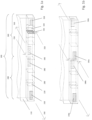
- Fig. 5 The system shows 100 of Fig. 1a in a schematic sectional view. Further elements of the first installation profile 200 are shown, which are constructed symmetrically in an analogous manner in the second installation profile.
- the installation profile 200 has a first flow guide device 215 located between the first outlet 210 and the first fan 220.
- the first flow guide device 215 ensures that the air which is blown by the first fan 220 in the direction of the first outlet 210 is deflected by 90°. This prevents undesirable air build-up and turbulence.
- the first installation profile 200 has, in addition to the components already mentioned, a second flow guide device 245 which deflects the air flow flowing in from the first inlet 240 by 90° before it enters the first heat exchanger material 230.
- the use of the second flow guide device 245 is similar to that of the first flow guide device 215.
- Fig. 6 shows an embodiment of a system 100a for ventilating a room, which is formed in an adapter profile 120a of a window 130a.
- the adapter profile 120a is arranged directly below the window 130a, which is installed in a wall 110a.
- Fig. 7 shows an embodiment of a system 100b which is similar to that shown in Fig. 6
- the system 100b is installed in a window frame 125b of a window 130b.
- the first outlet 210b and the second inlet 310b are visible.
- the aesthetic Impression of the window 130b and a surrounding wall 110b are not affected.
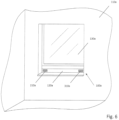
- Fig. 8 shows an embodiment of a system 100c which is similar to that shown in Fig. 7 In contrast to the execution of Fig. 7 However, the system 100c is as in Fig. 1b shown. This means that a first outlet 210c and a second inlet 310c are closer together. Otherwise, however, this is also an embodiment which is formed as part of a window frame 125c of a window 130c in a wall 110c.
- Fig. 9 shows an embodiment of a system 100d which is similar to that of Fig. 8 However, the system 100d is vertical, not like in Fig. 8 horizontally, installed in a window frame 125d of a window 130d.
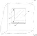
- Fig. 10 shows an embodiment of a system 100e which is similar to that of Fig. 9 However, in a modification, the System 100e is as in Fig. 1a shown. Accordingly, a first outlet 210e and a second inlet 310e are further apart from each other. Also in the embodiment of Fig. 10 the system is designed as part of a window frame 125e of a window 130e in a wall 110e.
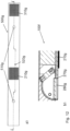
- Fig. 11a ) to c) show different representations of an embodiment of a system 100f according to the invention.
- Fig. 11a shows an external view of the system from a first side x
- Fig. 11b a sectional view along the line AA in Fig. 11a
- Fig. 11c External view of the system from a second side y, opposite the first.
- the 100f system is similar to the system of Fig. 1b The following description focuses on the differences.
- the axial fans 220f and 320f in system 100f are arranged so that their axes of rotation are turned out of the air flow by 45°. Such a fan arrangement further optimizes the flow to the heat exchanger 230f or 330f and leads to low power consumption of the fan.
- the present embodiment has sleeves 400f through which screws can be passed to attach the system to an adjacent wall.
- the sleeves serve to fix the components of the system 100f against each other.
- An example of a suitable sleeve is shown below in Fig. 13 shown.
- Fig. 12 a shows a rear view of an inner panel 500g suitable for the system 100f. It has two magnets 510g for attachment to the system 100f and a magnet 520g, the position of which can be detected by a Hall sensor (not shown here) arranged on the system 100f.
- the inner panel 500g has a first outlet 210g and a second inlet 310g.
- the arrangement of the inlet and the outlet along the longitudinal extension of the inner panel corresponds to the arrangement of the ventilation openings 280f and 380f of the system 100f in Fig. 11b ). In particular, it is asymmetrical with respect to the longitudinal extension of the installation profile.
- Fig. 12 b shows the effect of the inner panel on a section of the system 100f.
- the inner panel 500g is rotated here. If the inner panel 500g is rotated by 180° from its original position, in which the outlet 210g of the inner panel is above the ventilation opening 280g of the system 100f, the inner panel closes the system in conjunction with a web 270g.
- the web runs along an outside of a corpus 150f formed from a hollow profile, which is located behind the inner panel, in such a way that in this rotated arrangement of the inner panel no air can flow from the outlet 210g of the inner panel to the ventilation opening 280g in the corpus 150f.
- the Hall sensor detects the new position of the panel and thus makes it possible to switch off the ventilation system.
- Fig. 13 shows in three sub-figures 13a) to 13c) an embodiment of a sleeve 400h for a built-in profile, as it is used for example in the system 100f of Fig. 11 is shown.
- Fig. 13 a shows a longitudinal section of the sleeve 400h.
- the sleeve has a circumferential groove 410h at one lower end, into which a cable tie, for example, can be inserted to lock the sleeve to the installation profile.
- the sleeve 400h has a circumferential, bevelled edge 420h, with the help of which it can be arranged flush in a countersunk hole in the installation profile.
- Fig. 13b shows a cross-sectional view of a variant of the sleeve 400h in a cross-sectional plane near the lower end.
- the otherwise cylindrical sleeve has here has a circular inner cross-section, whereby the outer cross-section has a flattening 430h.
- a hole 440h in the area of the circumferential groove 410h at the level of the flattening serves to accommodate a locking pin.
- Fig. 13 c) shows a partial side view of this variant of the sleeve 400h, also in the area of its lower end.
Landscapes
- Engineering & Computer Science (AREA)
- Chemical & Material Sciences (AREA)
- Combustion & Propulsion (AREA)
- General Engineering & Computer Science (AREA)
- Mechanical Engineering (AREA)
- Life Sciences & Earth Sciences (AREA)
- Sustainable Development (AREA)
- Hydrology & Water Resources (AREA)
- Water Supply & Treatment (AREA)
- Civil Engineering (AREA)
- Health & Medical Sciences (AREA)
- General Chemical & Material Sciences (AREA)
- Electrochemistry (AREA)
- Chemical Kinetics & Catalysis (AREA)
- Organic Chemistry (AREA)
- Structural Engineering (AREA)
- Environmental & Geological Engineering (AREA)
- Public Health (AREA)
- Air-Conditioning Room Units, And Self-Contained Units In General (AREA)
- Ventilation (AREA)
- Building Environments (AREA)
- Duct Arrangements (AREA)
- Air-Flow Control Members (AREA)
Description
- Die Erfindung betrifft ein Einbauprofil zum Anbau an ein Wandsystem in einer Gebäudewand.
- Im Zuge von Energiesparmaßnahmen wird eine effiziente Belüftung von Räumen wie beispielsweise Wohnräumen oder Büroräumen zunehmend wichtig. Durch Öffnen eines Fensters kann zwar ein Luftaustausch mit der Außenluft erreicht werden, hierbei entweicht bei eingeschalteter Heizung oder Klimaanlage jedoch auch eine große Menge von Wärmeenergie aus dem Fenster bzw. es strömt warme Luft in den gekühlten Innenraum. Hierdurch geht ein erheblicher Teil der für das Heizen oder Kühlen aufgewendeten Energie verloren. Außerdem ist ein geöffnetes Fenster immer mit einer erhöhten Einbruchgefahr verbunden.
- Deshalb wurden bereits Systeme entwickelt, mit welchen bei der Lüftung eines Raums dezentral Wärme rückgewonnen werden kann. Unter "dezentral" ist dabei die Unabhängigkeit von einem installierten Heizungs- oder Kühlsystem zu verstehen. Gängige Systeme benötigen jedoch aufgrund der notwendigen Wärmespeicher viel Platz und ragen in den Raum herein. Außerdem sind zur Installation solcher Systeme häufig umfangreiche Baumaßnahmen nötig.
- Es wäre deshalb wünschenswert, eine Lüftung mit dezentraler Wärmerückgewinnung mit geringerem Aufwand, insbesondere mit geringerem Platzbedarf, vorzusehen.
- Aus dem Dokument
US 3, 941,185 ist ein Lüftungsgerät zur Wohnraumbelüftung bekannt. Ein längliches Gehäuse ist an einem Ende mit einem Ventilator ausgestattet, der einen reversiblen Motor hat, um die Drehrichtung des Ventilators zu steuern. Eine Folge von Wärmetauscher-Platten ist im Gehäuse parallel zur Richtung der Luftströmung positioniert. Thermostaten an beiden Enden des Gehäuses messen die Temperatur der vorbeiströmenden Luft und steuern dadurch die Drehrichtung des Ventilators. - Aus Dokument
FR2 509 022 - Erfindungsgemäß wird ein Einbauprofil gemäß Anspruch 1 sowie ein System zur Belüftung eines Raums gemäß Anspruch 9 bereitgestellt. Bevorzugte Ausführungen können beispielsweise den Unteransprüchen entnommen werden.
- Gemäß einem ersten Aspekt betrifft die Erfindung also ein Einbauprofil gemäß Anspruch 1 zum Anbau an ein Wandsystem in einer Gebäudewand.
- Das Einbauprofil weist einen Profilinnenraum auf, der als Strömungsraum ausgebildet ist, und welcher einen Einlass und einen Auslass aufweist. Das Einbauprofil weist ferner ein Wärmetauschermaterial auf, welches sich im Strömungsraum strömungsmäßig, d. h. durchströmbar zwischen dem Einlass und dem Auslass befindet. Ferner weist es ein Ventilationssystem zur bidirektionalen Strömungsförderung durch das Wärmetauschermaterial auf. Das Ventilationssystem weist dabei wenigstens einen Ventilator auf, der unter Belassen eines Vergleichmäßigungsabstands vom Wärmetauschermaterial im Strömungsraum angeordnet ist.
- Unter einem Wandsystem werden hier Elemente verstanden, welche typischerweise in einer Wand eingebaut sind. Hierbei kann es sich beispielsweise um ein Fenster, eine Tür, eine Fensterbank, eine Fußleiste oder dergleichen handeln. Es kann sich jedoch auch um einen Durchbruch handeln, welcher eigens für das Einsetzen eines Einbauprofils ausgebildet ist.
- Durch das erfindungsgemäße Einbauprofil wird eine deutliche Verkleinerung des für eine dezentrale Lüftung mit Wärmerückgewinnung notwendigen Platzes und eine Steigerung der Effektivität und des Wärmerückgewinnungsgrades erreicht, da durch den Vergleichmäßigungsabstand eine gleichmäßigere Durchströmung des Wärmetauschermaterials erreicht wird. Im Gegensatz dazu würde bei unmittelbarem Angrenzen des Ventilators an das Wärmetauschermaterial eine strömungsmäßige Totzone, welche sowohl bei Radialwie auch bei Axialventilatoren auftritt, zu einer erheblich ungleichmäßigen Durchströmung des Wärmetauschermaterials führen. Damit wäre die Wärmespeicherkapazität des Wärmetauschermaterials nicht vollständig genutzt.
- Das Einbauprofil weist vorzugsweise eine äußere Hülle auf, welche beispielsweise aus Stahl, Aluminium oder Kunststoff hergestellt sein kann. Im Querschnitt betrachtet ist diese äußere Hülle des Einbauprofils, oder anders ausgedrückt das Einbauprofil an sich, kleiner als eine gedachte rechteckförmige Begrenzung, wobei mindestens eine Seite der rechteckförmigen Begrenzung eine Länge von weniger als 15 cm, besonders bevorzugt von weniger als 10 cm und ganz besonders bevorzugt von weniger als 8 cm aufweist. Besonders bevorzugt weist auch eine zu einer solchen Seite quer stehende Seite der rechteckförmigen Begrenzung eine Länge von weniger als 15 cm, besonders bevorzugt von weniger als 10 cm und ganz besonders bevorzugt von weniger als 8 cm auf.
- Der Einlass und der Auslass des Profilinnenraums können als einfache Öffnungen ausgebildet sein. Bevorzugt sind sie jedoch mit Lüftungsgittern versehen, welche das Eindringen von Gegenständen verhindern. Zum Schutz vor Staub und Insekten können ferner feinmaschige Fliegengitter an dem Einlass und dem Auslass angebracht sein. Sollen der Einlass oder der Auslass verschließbar ausgebildet werden, so können hierfür beispielsweise Lamellen oder Klappen verwendet werden.
- In einer bevorzugten Ausführungsform weist das Einbauprofil eine mit Magneten am Einbauprofil befestigte Innenblende auf. Die Innenblende weist zwei den Lüftungsöffnungen zugeordnet angeordnete Lüftungsfelder mit Lüftungsschlitzen oder Lüftungsbohrungen auf. Nimmt man diese Blende ab und dreht diese um 180°, wird die Lüftungsöffnung dadurch verschlossen, weil die Lüftungsfelder nicht mehr über den Lüftungsöffnungen angeordnet sind. Das Lüftungsgerät ist so vollkommen schließbar, Luft kann nicht mehr eindringen. Zusätzlich ist außermittig ein zusätzlicher Magnet befestigt, so dass ein am Einbauprofil angebrachter Hall-Sensor die Position der Blende detektieren kann. Das Ventilationssystem kann somit abschaltet werden, sobald die Blende abgenommen oder verdreht aufgesetzt wird.
- Es sei verstanden, dass die Bezeichnungen "Einlass" und "Auslass" sich auf eine bestimmte Strömungsrichtung der Luft beziehen, welche durch die Drehrichtung des Ventilators vorgegeben ist. Für den Betrieb des Einbauprofils zur Lüftung mit Wärmerückgewinnung eines Raums ist es vorteilhaft, dass die Strömungsrichtungen alternierend abgewechselt werden. Insofern ist es bei einem Einbauprofil nicht vorgesehen, anhand konstruktiver Merkmale zwischen einem Einlass und einem Auslass zu unterscheiden. Vielmehr wird bei Änderung der Strömungsrichtung ein Einlass zu einem Auslass und ein Auslass zu einem Einlass. Das Einbauprofil ist insofern bevorzugt symmetrisch ausgebildet, was in diesem Fall bedeutet, dass Luft sowohl vom Einlass zum Auslass wie auch umgekehrt strömen kann. Nachfolgend wird im Sinne der Klarheit für ein Strukturelement, welches als Einlass oder Auslass dienen kann, in der gesamten Beschreibung nur jeweils eine der Bezeichnungen verwendet, ohne dass dies bedeuten würde, dass das Strukturmerkmal nicht auch gemäß der anderen Bezeichnung verwendbar ist.
- Zwischen dem Ventilator und dem Einlass oder dem Auslass, welcher an den Ventilator strömungsmäßig angrenzt, d. h. im Raum ohne Wärmetauschermaterial im Strömungsfluss des Ventilators, ist bevorzugt ferner eine Strömungsleitvorrichtung vorgesehen. Diese kann die Luft, welche der Ventilator ansaugt oder ausbläst möglichst verlustarm umlenken; insbesondere umlenken von einem Durchlass (Einlass oder Auslass) zum Ventilator oder umgekehrt.
- Das Wärmetauschermaterial, welches sich im Strömungsraum zwischen dem Einlass und dem Auslass befindet, ist derart ausgebildet, dass es sich erwärmt, wenn es von Luft mit einer höheren Temperatur als der Temperatur des Wärmetauschermaterials durchströmt wird. Ebenso kühlt es sich ab, wenn es von einer Luft mit einer geringeren Temperatur als der Temperatur des Wärmetauschermaterials durchströmt wird. Wird also der Ventilator so geschaltet, dass Luft aus einem beheizten Raum ins Freie geleitet wird, so kann sich ein vorher abgekühltes Wärmetauschermaterial erwärmen. Der Luft wird dabei die Energie entzogen. Kehrt anschließend der Ventilator die Drehrichtung um, so dass Luft von der kalten Außenseite in den Raum geleitet wird, so strömt diese Luft an dem wärmeren Wärmetauschermaterial vorbei. Dabei wird die Luft erwärmt. Insgesamt wird dabei eine Rückgewinnung eines Teils der ansonsten beim konventionellen Lüften verloren gehenden Wärme erreicht. In klimatisierten Räumen funktioniert das Prinzip entsprechend umgekehrt.
- Geeignete Wärmetauschermaterialien sind Keramiken, insbesondere solche mit einem Anteil an Metalloxiden oder Metallen. Beispielsweise wird hierfür Aluminiumoxid verwendet. Auch reine Metalle oder Metalllegierungen sowie Kunststoffe können als Wärmetauschermaterialien verwendet werden.
- Ein Ventilationssystem zur bidirektionalen Strömungsführung durch das Wärmetauschermaterial weist wenigstens einen Ventilator auf. Gemäß einer Ausführung weist es genau einen Ventilator auf, welcher bidirektional betreibbar ist. Eine Änderung des Strömungsflusses ist dadurch erreichbar, dass der Ventilator umgepolt wird und dabei seine Drehrichtung ändert. Alternativ kann das Ventilationssystem auch einen ersten Ventilator, welcher zwischen dem Wärmetauschermaterial und dem Einlass angeordnet ist, und einen zweiten Ventilator, welcher zwischen dem Wärmetauschermaterial und dem Auslass angeordnet ist, aufweisen. In diesem Fall gibt es zwei Möglichkeiten. Zum einen ist es möglich, dass beide Ventilatoren gleichzeitig laufen und den Strömungsfluss in die gleiche Richtung aufrecht erhalten. Alternativ ist es möglich, einen der beiden Ventilatoren nur für den Strömungsfluss in eine Richtung und den anderen der beiden Ventilatoren nur für den Strömungsfluss in die andere Richtung zu verwenden. Dann ruht bevorzugt immer ein Ventilator, während sich der andere dreht. Anders ausgedrückt sind bei dieser Ausführung der erste und der zweite Ventilator abwechselnd betreibbar, wobei jeder Ventilator nur in einer Strömungsrichtung betreibbar ist.
- Gemäß einer Ausführung ist der Ventilator ein Axialventilator.
- Durch den Vergleichmäßigungsabstand, welchen der Ventilator zum Wärmetauschermaterial einhält, wird erreicht, dass ein durch den Ventilator erzeugter Luftstrom gleichmäßig durch das Wärmetauschermaterial geht. Bereits erwähnte Totzonen von Ventilatoren - bei Axialventilatoren regelmäßig um den Drehpunkt angeordnete Zonen und bei Radialventilatoren aufgrund des Aufbaus - wirken dann nicht mehr derart, dass eine ausreichende Anströmung auf das Wärmetauschermaterial verhindert wird. Stattdessen ist es möglich, dass auch in Bereichen, welche bei einem unmittelbar an das Wärmetauschermaterial angrenzenden Ventilator aufgrund einer Totzone des Ventilators nicht ausreichend durchströmt sind, eine Wärmeaufladung bzw. Wärmerückführung erfolgt. Das sonst auftretende Problem schlechter Wirkungsgrade wird vermieden. Mit dem Konzept des Vergleichmaßigungsabstandes werden zusammenfassend Totzonen vermieden und der Wirkungsgrad erheblich verbessert.
- Ohne Vergleichmäßigungsabstand bläst beispielsweise ein Axiallüfter ungleichmäßig in den Wärmetauscher hinein. Ein Außenbereich der Querschnittsfläche wird deutlich stärker durchströmt als ein zentraler Bereich der Querschnittsfläche. Dadurch wird der zentrale Bereich nicht ausreichend mit warmer Luft vorgewärmt. Beim zweiten Zyklus, also beim Hindurchsaugen von Außenluft, wird zwar der Wärmetauscher gleichmäßig durchströmt. Im zentralen Bereich der Querschnittsfläche des Wärmetauschers wird aber nun kältere Luft einströmen, weil in diesem Bereich nur wenig gespeicherte Wärmeenergie vorhanden ist. Auf diese Weise leidet der Wirkungsgrad des Wärmetauschers als Ganzes. Durch Vorsehen des Vergleichmäßigungsabstands dagegen wird der Luftstrom des Lüfters so verwirbelt und gebrochen, dass auch beim ersten Zyklus die Luft gleichmäßig im Außenbereich wie im zentralen Bereich durch den Wärmetauscher strömt und diese gleichmäßig erwärmt wird, um im zweiten Zyklus entsprechend gleichmäßig im äußeren wie im zentralen Bereich Wärme an einströmende Außenluft abgeben zu können.
- In einer Ausführungsform ist der Ventilator ein Axialventilator, welcher ein Ventilatorrad hat, dessen äußerer Umfang in mindestens einer senkrecht zur Achse des Ventilators stehenden Ebene durch einen Kreis beschreibbar ist. Der Vergleichmäßigungsabstand ist bei dieser Ausführungsform mit einer Abweichung von maximal 20% gleich dem Radius des Kreises. Bevorzugt liegt die Abweichung in einem Bereich kleiner 10%. Besonders vorteilhaft entspricht der Vergleichmäßigungsabstand genau dem Radius des Kreises.
- Der Vergleichmäßigungsabstand beträgt bevorzugt weniger als 10 cm, besonders bevorzugt beträgt er weniger als 3 cm. Mit solchen Werten kann eine ausreichende Verteilung des Luftstroms bei gleichzeitiger Verringerung der Einbaumaße erreicht werden. Die ausreichende Darstellung eines Vergleichmäßigungsabstandes ermöglicht letztlich die Verringerung der Einbaumaße, da ausreichend Wärmespeicher mit guter Ausnutzung zur Verfügung steht.
- In dem Vergleichmäßigungsraum ist erfindungsgemäß ein Strömungsvergleichmäßiger angeordnet, welcher zusätzlich für eine gleichmäßige Verteilung des Luftstroms sorgt. Beispielsweise kann hierzu eine Watte, ein Vlies oder ein sonstiges poröses Material verwendet werden. Durch einen solchen Strömungsvergleichmäßiger kann der für eine ausreichende Vergleichmäßigung notwendige Vergleichmäßigungsabstand verringert werden, vorteilhaft können damit auch die Einbaumaße weiter verringert werden.
- Eine weitere Optimierung der Anströmung des Wärmetauschers wird durch eine Schrägstellung des Ventilators erreicht. Der Ventilator ist so angeordnet, dass seine Drehachse um einen Winkel zwischen 30° und 60° aus dem Luftstrom herausgedreht ist. Hierdurch wird der Luftstrom vor dem Eintritt in den Wärmetauscher zusätzlich verwirbelt, so dass der Wärmetauscher gleichmäßiger angeströmt werden kann. Eine solche Ventilatoranordnung führt auch zu einem niedrigen Stromverbrauch des Ventilators.
- Gemäß einer Ausführung verläuft ein Strömungspfad durch das Wärmetauschermaterial quer zu jeweiligen Strömungspfaden durch den Einlass und durch den Auslass. Dies bedeutet anders ausgedrückt, dass die Luft nach Eintritt durch den Einlass zunächst um etwa 90° umgelenkt wird, anschließend durch den Ventilator und durch das Wärmetauschermaterial strömt, anschließend noch einmal um 90° umgelenkt wird, und dann durch den Auslass das Einbauprofil wieder verlässt. Mit einer solchen Anordnung kann der Querschnitt des Einbauprofils klein gehalten werden, da die Länge des Einbauprofils für die Anordnung des Wärmetauschermaterials genutzt werden kann. Alternativ können sich jedoch auch Einlass und Auslass einander gegenüberliegen, wobei sich das Wärmetauschermaterial sowie der Ventilator zwischen dem Einlass und dem Auslass befinden. Eine solche Ausführung kann beispielsweise dann vorteilhaft sein, wenn eine längere Strecke zwischen Einlass und Auslass zur Verfügung steht.
- Bevorzugt ist das Wärmetauschermaterial in einer Kassette beinhaltet. Damit kann ein Wärmetauschermaterial verwendet werden, welches beispielsweise pulver- oder kugelförmig ist und ohne die umschließende Kassette mit dem Luftstrom weggeblasen werden würde. Alternativ kann ein Wärmetauschermaterial eingesetzt bzw. verwendet werden, welches fest ist und unmittelbar an dem Einbauprofil befestigt ist. Das Wärmetauschermaterial kann homogen oder auch inhomogen verteilt sein.
- Bevorzugt weist das Einbauprofil einen Schallschutz zur Abschirmung von Ventilatorgeräuschen auf. Damit kann eine etwaige Geräuschbelästigung in dem Raum, welcher mit Hilfe des Einbauprofils belüftet werden soll, verringert oder vermieden werden. Ein Schallschutz kann beispielsweise in Form einer schalldämmenden Isolierung vorgesehen sein. Eine schalldämmende Isolierung kann gleichzeitig wärmeisolierend sein. Alternativ kann eine hauptsächlich wärmedämmende Isolierung vorgesehen sein, was den Wirkungsgrad weiter verbessern kann.
- Bevorzugt verfügt das Einbauprofil über Hülsen, die im Strömungsraum senkrecht zur Strömungsrichtung angeordnet sind. Diese Hülsen sind geeignet, um Lasten abzufangen und/oder um Schrauben aufzunehmen, über die z.B. ein Fenster oder eine Tür mit dem Mauerwerk verbunden werden kann. Eine solche Schraubverbindung durch die Hülse trägt auch zu einem verbesserten Einbruchschutz bei. Darüberhinaus können die Hülsen als Positionsarretierung für verschiedene Teile des Einbauprofils, wie Ventilator, Wärmetauscher oder Strömungsleitvorrichtung dienen. Die Hülsen werden bevorzugt direkt in das Profil eingeschoben. Gemäß einem zweiten Aspekt betrifft die Erfindung ein System zur Belüftung eines Raums, welches ein Einbauprofil gemäß dem ersten Aspekt der Erfindung sowie ein weiteres Einbauprofil gemäß dem ersten Aspekt der Erfindung aufweist. Das Einbauprofil und das weitere Einbauprofil werden vorteilhaft alternierend gegenläufig geschaltet.
- Mögliche Ausführungen und Vorteile, welche mit Bezug auf das Einbauprofil gemäß dem ersten Aspekt der Erfindung beschrieben sind, beziehen sich ebenso auf das System gemäß dem zweiten Aspekt der Erfindung. So können sowohl für das Einbauprofil wie auch für das weitere Einbauprofil beliebige Ausführungen, wie mit Bezug auf den ersten Aspekt der Erfindung erläutert, verwendet werden, wobei das System gemäß dem zweiten Aspekt der Erfindung alle Merkmale des ersten Aspektes der Erfindung beinhaltet. Bevorzugt sind das Einbauprofil und das weitere Einbauprofil identisch ausgebildet.
- Unter einer alternierenden gegenläufigen Schaltung wird verstanden, dass ein Einbauprofil Luft aus dem zu belüftenden Raum nach außen bläst, während gleichzeitig das andere Einbauprofil Luft aus der Umgebung in den Raum herein bläst. Damit ist sichergestellt, dass im Raum kein Über- oder Unterdruck entsteht.
- Wenn sich während eines gleichmäßigen Betriebs des Einbauprofils und des weiteren Einbauprofils das Wärmetauschermaterial in demjenigen Einbauprofil, welches Luft aus dem Raum hinaus bläst, ausreichend erwärmt hat und das Wärmetauschermaterial in dem anderen Einbauprofil sich entsprechend abgekühlt hat, wird die Strömungsrichtung der Luft durch die beiden Einbauprofile umgekehrt. Dies kann auf die weiter oben beschriebenen Arten erfolgen. Dann wird durch das nunmehr warme Wärmetauschermaterial die von außen hereinströmende Luft angewärmt, während sich das nunmehr kalte Wärmetauschermaterial durch die von innen nach außen strömende Luft aufwärmt. Damit wird eine optimale Energierückgewinnung bei gleichmäßiger Lüftung und Vermeidung von Über- oder Unterdruck im Raum erreicht.
- Das Einbauprofil und das weitere Einbauprofil können unabhängig voneinander an unterschiedlichen Stellen im Raum angeordnet sein. Gemäß einer Ausführung sind sie miteinander verbunden. Beispielsweise können sie so miteinander verbunden sein, dass sie zusammen eine stangenförmige Struktur ergeben.
- Wenn das Einbauprofil und das weitere Einbauprofil miteinander verbunden sind, ist bevorzugt das System gemäß einer Ausführung im Adapterprofil eines Fensters oder als Adapterprofil eines Fensters ausgebildet. Dies ermöglicht einen Einbau des Systems unmittelbar unterhalb, oberhalb oder auch seitlich an einem Fenster. Ebenso könnte ein solches System in einem separaten Mauerdurchbruch, in einem Türrahmen, in einer Türschwelle, oder an anderen Orten angeordnet sein.
- Gemäß einer bevorzugten Ausführung ist das System als Teil eines Fensterrahmens ausgebildet. Damit kann das System als Teil eines Fensters verkauft und eingebaut werden. Es sind keine zusätzlichen Bau- oder Installationsarbeiten erforderlich. Außerdem kann das System damit formschön in ein ohnehin einzusetzendes Fenster integriert werden.
- Weitere Merkmale und Vorteile werden bei Betrachtung der nachfolgend mit Bezug auf die Figuren beschriebenen Ausführungsbeispiele offensichtlich werden.
- Fig. 1a
- zeigt ein nicht durch die beanspruchte Erfindung abgedecktes Ausführungsbeispiel eines Systems mit zwei Einbauprofilen.
- Fig. 1b
- zeigt ein alternatives, nicht durch die beanspruchte Erfindung abgedecktes Ausführungsbeispiel eines Systems.
- Fig. 2
- zeigt das System von
Fig. 1a in einem anderen Einbauzustand. - Fig. 3
- zeigt eine Vorderansicht des Systems von
Fig. 1a . - Fig. 4
- zeigt eine Rückansicht des Systems von
Fig. 1a . - Fig. 5
- zeigt das System von
Fig. 1a in einer Schnittansicht. - Fig. 6
- zeigt ein Ausführungsbeispiel eines Systems wie in
Fig. 1a dargestellt, welches in einem Adapterprofil eines Fensters ausgebildet ist. - Fig. 7
- zeigt ein Ausführungsbeispiel eines Systems wie in
Fig. 1a dargestellt, welches als Teil eines Fensterrahmens ausgebildet ist. - Fig. 8
- zeigt ein Ausführungsbeispiel eines Systems wie in
Fig. 1b dargestellt, welches als Teil eines Fensterrahmens ausgebildet ist. - Fig. 9
- zeigt ein Ausführungsbeispiel eines Systems wie in
Fig. 1b dargestellt, welches als Teil eines Fensterrahmens ausgebildet ist und vertikal angeordnet ist. - Fig. 10
- zeigt ein Ausführungsbeispiel eines Systems wie in
Fig. 1a dargestellt, welches als Teil eines Fensterrahmens ausgebildet und vertikal angeordnet ist. - Fig. 11
- zeigt in drei Teilfiguren a), b) und c) eine Variante eines Ausführungsbeispiels eines Systems gemäß dem zweiten Aspekt der Erfindung, wie in
Fig. 1b dargestellt. - Fig. 12
- zeigt in Teilfigur a) eine Innenblende zur Verwendung in einem System gemäß dem zweiten Aspekt der Erfindung und in Teilfigur b) das Wirkprinzip der um 180 ° verdrehten Innenblende.
- Fig. 13
- zeigt in drei Ansichten der
Fig. 13a ), b) und c) eine Hülse für ein Einbauprofil. -
Fig. 1a zeigt ein nicht durch die beanspruchte Erfindung abgedecktes System 100. Dieses weist ein erstes Einbauprofil 200 und ein zweites Einbauprofil 300 auf. Die Einbauprofile 200, 300 sind nebeneinander angeordnet, sodass das System 100 insgesamt eine langgestreckte Form hat. - Das System 100 ist in eine Wand 110 eingebaut. Damit ermöglicht es die Belüftung eines Raums.
- Das erste Einbauprofil 200 weist einen ersten Auslass 210, einen ersten Einlass 240 und strömungsmäßig dazwischenliegend einen ersten Ventilator 220 und ein erstes Wärmetauschermaterial 230 auf. Der Ventilator 220 saugt Luft entsprechend einer Strömungsrichtung 250 von einer Außenseite an, welcher durch die Wand 110 von einem Innenraum getrennt wird, leitet diese durch das Wärmetauschermaterial 230, und bläst sie schließlich durch den ersten Auslass 210 entsprechend einer Strömungsrichtung 260 in den Raum. Mit Hilfe des Wärmetauschermaterials 230 wird die Luft vor Eintritt in den Raum temperiert. Im typischen Fall, in welchem das System 100 in einer Heizperiode angewendet wird, hat das erste Wärmetauschermaterial 230 eine höhere Temperatur als die durch den ersten Einlass 240 einströmende Luft. Dadurch wird die Luft, bevor sie in den Raum einströmt, erwärmt.
- Umgekehrt, jedoch analog funktioniert im gezeigten Fall das zweite Einbauprofil 300. Das zweite Einbauprofil 300 weist einen zweiten Einlass 310, einen zweiten Ventilator 320, ein zweites Wärmetauschermaterial 330 und einen zweiten Auslass 340 auf.
- Mit Hilfe des zweiten Ventilators 320 wird Luft entlang einer Strömungsrichtung 350 durch den zweiten Einlass 310 von dem Raum eingesaugt. Anschließend bläst der zweite Ventilator 320 die Luft durch das zweite Wärmetauschermaterial 330, welches beim Betrieb in der Heizperiode typischerweise eine niedrigere Temperatur als die durchströmende Luft aufweist. Dabei wird das zweite Wärmetauschermaterial 330 erwärmt. Schließlich strömt die Luft durch den zweiten Auslass 340 ins Freie.
- Durch die beschriebene Funktionalität wird der Raum, welcher durch die Wand 110 von der Umgebungsluft abgetrennt wird, gleichzeitig be- und entlüftet. Hierdurch wird das Entstehen eines Über- oder Unterdrucks vermieden, wodurch auch ein ungewolltes und unkontrolliertes Nachströmen von Luft durch Ritzen, Schlüssellöcher oder ähnliches vermieden wird. Durch das System 100 wird jedoch insbesondere auch vermieden, dass angewärmte Heizungsluft unter hohem Energieverlust ins Freie strömt. Stattdessen wird die Wärme der ausströmenden Luft in dem zweiten Wärmetauschermaterial 330 gespeichert. Die einströmende Luft wird durch das erste Wärmetauschermaterial 230 erwärmt. Nach einer bestimmten Zeit werden die Drehrichtungen der Ventilatoren umgekehrt, so dass die im zweiten Wärmetauschermaterial 330 gespeicherte Wärme zum Heizen der nunmehr mit Hilfe des zweiten Einbauprofils 300 in den Raum geblasenen Luft verwendet wird. Gleichzeitig wird dann Luft mit Hilfe des ersten Einbauprofils 200 aus dem Raum ins Freie geblasen, und die Wärme wird in dem ersten Wärmetauschermaterial 230 gespeichert. Durch Umpolen der Ventilatoren sind die beschriebenen Vorgänge beliebig oft sequentiell wiederholbar, so dass ein faktisch kontinuierlicher Betrieb des Systems 100 sichergestellt ist.
-
Fig. 1b zeigt ein alternatives, nicht durch die beanspruchte Erfindung abgedecktes Ausführungsbeispiel des inFig. 1a dargestellten Systems, welches dahingehend abgewandelt ist, dass ein erster Einlass 240c und ein zweiter Auslass 340c weiter voneinander beabstandet sind als bei dem System vonFig. 1a . Dementsprechend sind ein erster Auslass 210c und ein zweiter Einlass 310c näher beieinander angeordnet. Ansonsten bestehen keine Unterschiede zu dem inFig. 1a dargestellten Ausführungsbeispiel, weshalb auf eine Wiederholung verzichtet wird. -
Fig. 2 zeigt das System 100 vonFig. 1a in einem anderen Einbauzustand. Das System 100 ist dabei im Unterschied zum horizontalen Einbau inFig. 1a vertikal eingebaut. Dabei befindet sich das zweite Einbauprofil 300 über dem ersten Einbauprofil 200. -
Fig. 3 zeigt eine Vorderansicht des Systems 100 vonFig. 1a . Dabei sind lediglich der erste Auslass 210 und der zweite Einlass 310 sichtbar. Die anderen Elemente des ersten Einbauprofils 200 und des zweiten Einbauprofils 300 sind in diesem Zustand nicht sichtbar. Die gezeigte Vorderansicht entspricht typischerweise derjenigen, welche von einem Raum aus zu sehen ist. Der erste Auslass 210 und der zweite Einlass 310 sind dabei bewusst ausreichend weit voneinander beabstandet, damit durch den ersten Auslass 210 in den Raum eingeblasene Luft nicht gleich durch den zweiten Einlass 310 wieder abgesaugt wird. -
Fig. 4 zeigt eine Rückansicht des Systems 100 vonFig. 1a , welches typischerweise von einer Außenseite, also vom Freien oder einen kälteren Raum (z. B. Garage oder dergleichen) aus zu sehen ist. Hierbei sind von dem ersten Einbauprofil 200 und dem zweiten Einbauprofil 300 lediglich der erste Einlass 240 und der zweite Auslass 340 zu sehen. Diese sind zwar nahe zueinander gelegen, aufgrund des üblicherweise im Freien herrschenden Winds und einer geeigneten Luftführung, z.B. durch Lamellen, welche die Luftströme in unterschiedliche Richtungen lenken, ist dies jedoch meistens unproblematisch. Wenn bei einer Anwendung die Gefahr besteht, dass die ausströmende Luft gleich wieder eingesaugt werden könnte, beispielsweise bei Installation in windgeschützten Bereichen, so kann bevorzugt das System verwendet werden, welches inFig. 1b dargestellt ist. -
Fig. 5 zeigt das System 100 vonFig. 1a in einer schematischen Schnittansicht. Dabei sind weitere Elemente des ersten Einbauprofils 200 gezeigt, die beim zweiten Einbauprofil symmetrisch in analoger Weise aufgebaut sind. - Das Einbauprofil 200 weist eine strömungsmäßig zwischen dem ersten Auslass 210 und dem ersten Ventilator 220 gelegene erste Strömungsleitvorrichtung 215 auf. Die erste Strömungsleitvorrichtung 215 sorgt dafür, dass die Luft, welche von dem ersten Ventilator 220 in Richtung des ersten Auslasses 210 geblasen wird, um 90° umgelenkt wird. Damit wird unerwünschter Luftstau und Verwirbelung vermieden.
- Ebenso ist
Fig. 5 zu entnehmen, dass das erste Einbauprofil 200 neben den bereits erwähnten Komponenten eine zweite Strömungsleitvorrichtung 245 aufweist, welche den von dem ersten Einlass 240 einströmenden Luftstrom um 90° umlenkt, bevor dieser in das erste Wärmtauschermaterial 230 eintritt. Der Nutzen der zweiten Strömungsleitvorrichtung 245 ist ähnlich zu demjenigen der ersten Strömungsleitvorrichtung 215. -
Fig. 6 zeigt ein Ausführungsbeispiel eines Systems 100a zur Belüftung eines Raums, welches in einem Adapterprofil 120a eines Fensters 130a ausgebildet ist. Das Adapterprofil 120a ist dabei unmittelbar unterhalb des Fensters 130a angeordnet, welches in einer Wand 110a eingebaut ist. - Von jeweiligen Einbauprofilen in dem System 100a ist in der gezeigten Darstellung, wie sie vom Inneren des Raumes aus gesehen wird, lediglich der erste Auslass 210a und der zweite Einlass 310a sichtbar. Es ragen keine unförmigen Elemente in den Raum herein. Auch sonst wird der ästhetische Eindruck des Fensters 130a und der umgebenden Wand 110a nicht beeinträchtigt.
-
Fig. 7 zeigt ein Ausführungsbeispiel eines Systems 100b, welches ähnlich demjenigen ist, welches inFig. 6 gezeigt ist. Im Unterschied zur Ausführung vonFig. 6 ist das System 100b in einen Fensterrahmen 125b eines Fensters 130b eingebaut. Auch in diesem Fall sind lediglich der erste Auslass 210b und der zweite Einlass 310b sichtbar. Der ästhetische Eindruck des Fensters 130b und einer umgebenden Wand 110b werden nicht beeinträchtigt. -
Fig. 8 zeigt ein Ausführungsbeispiel eines Systems 100c, welches ähnlich demjenigen ist, welches inFig. 7 gezeigt ist. Im Unterschied zur Ausführung vonFig. 7 ist das System 100c jedoch wie inFig. 1b dargestellt ausgebildet. Damit sind ein erster Auslass 210c und ein zweiter Einlass 310c näher zusammen. Ansonsten handelt es sich jedoch auch hierbei um eine Ausführung, welche als Teil eines Fensterrahmens 125c eines Fensters 130c in einer Wand 110c ausgebildet ist. -
Fig. 9 zeigt ein Ausführungsbeispiel eines Systems 100d, welches ähnlich demjenigen vonFig. 8 aufgebaut ist. In Abwandlung dazu ist jedoch das System 100d vertikal, also nicht wie inFig. 8 horizontal, in einen Fensterrahmen 125d eines Fensters 130d eingebaut. -
Fig. 10 zeigt ein Ausführungsbeispiel eines Systems 100e, welches ähnlich demjenigen vonFig. 9 aufgebaut ist. In Abwandlung dazu ist jedoch das System 100e wie inFig. 1a dargestellt aufgebaut. Dementsprechend sind ein erster Auslass 210e und ein zweiter Einlass 310e weiter voneinander beabstandet. Auch in dem Ausführungsbeispiel vonFig. 10 ist das System als Teil eines Fensterrahmens 125e eines Fensters 130e in einer Wand 110e ausgebildet. - Die
Fig. 11a ) bis c) zeigen unterschiedliche Darstellungen eines erfindungsgemäßen Ausführungsbeispiels eines Systems 100f.Fig. 11a ) zeigt eine Außenansicht des Systems von einer ersten Seite x,Fig. 11b ) eine Schnittdarstellung entlang der Linie A-A inFig. 11a), und Fig. 11c ) Außenansicht des Systems von einer zweiten, der ersten gegenüberliegenden Seite y. - Das System 100f ist ähnlich dem System von
Fig. 1b aufgebaut. Die nachfolgende Beschreibung konzentriert sich auf die Unterschiede. In Abwandlung zu dem System derFig. 1b sind die Axialventilatoren 220f und 320f im System 100f so angeordnet, dass ihre Drehachsen um 45° aus dem Luftstrom herausgedreht sind. Eine solche Ventilatoranordnung optimiert die Anströmung des Wärmetauschers 230f bzw. 330f zusätzlich und führt zu einem niedrigen Stromverbrauch des Ventilators. - Darüberhinaus verfügt das vorliegende Ausführungsbeispiel über Hülsen 400f, durch die Schrauben zur Befestigung des Systems an einer angrenzenden Wand geführt werden können. Gleichzeitig dienen die Hülsen zur Fixierung der Bauteile des System 100f gegeneinander. Ein Beispiel einer geeigneten Hülse ist unten in
Fig. 13 dargestellt. -
Fig. 12 a ) zeigt eine Rückansicht einer für das System 100f geeigneten Innenblende 500g. Sie hat zwei Magneten 510g zur Befestigung an dem System 100f und einen Magneten 520g, dessen Position von einem hier nicht dargestellten, am System 100f angeordneten Hall-Sensor detektiert werden kann. Die Innenblende 500g hat einen ersten Auslass 210g und einen zweiten Einlass 310g. Die Anordnung des Einlasses und des Auslasses entlang der Längserstreckung der Innenblende entspricht der Anordnung der Lüftungsöffnungen 280f und 380f des Systems 100f inFig. 11b ). Insbesondere ist sie bezüglich der Längserstreckung des Einbauprofils unsymmetrisch. -
Fig. 12 b ) zeigt die Wirkung der Innenblende an einem Ausschnitt des Systems 100f. Die Innenblende 500g ist hier verdreht angeordnet. Wird die Innenblende 500g aus ihrer ursprünglichen Position, bei der der Auslass 210g der Innenblende über der Lüftungsöffnung 280g des Systems 100f liegt, um 180° verdreht angebracht, so verschließt die Innenblende im Zusammenwirken mit einem Steg 270g das System. Der Steg verläuft an einer Außenseite eines hinter der Innenblende liegenden, von einem Hohlprofil gebildeten Corpus 150f so, dass in dieser gedrehten Anordnung der Innenblende keine Luft vom Auslass 210g der Innenblende zur Lüftungsöffnung 280g im Corpus 150f strömen kann. Der Hall-Sensor detektiert die neue Position der Blende und ermöglicht so, ein Abschalten des Ventilationssystems zu veranlassen. -
Fig. 13 zeigt in drei Teilfiguren 13a) bis 13c) eine Ausführungsform einer Hülse 400h für ein Einbauprofil, wie es beispielsweise im System 100f derFig. 11 dargestellt ist.Fig. 13 a ) zeigt einen Längsschnitt der Hülse 400h. Die Hülse verfügt an einem unteren Ende über eine umlaufende Nut 410h, in die zur Arretierung der Hülse am Einbauprofil beispielsweise ein Kabelbinder aufgenommen werden kann. An einem gegenüberliegenden, oberen Ende verfügt die Hülse 400h über einen umlaufenden, abgeschrägten Rand 420h, mit Hilfe dessen sie in einer abgesenkten Bohrung im Einbauprofil bündig angeordnet werden kann. -
Fig. 13b ) zeigt eine Querschnittsansicht einer Variante der Hülse 400h in einer nahe dem unteren Ende liegenden Querschnittsebene. Die ansonsten zylindrische Hülse verfügt hier über einen kreisrunden Innenquerschnitt, wobei der Außenquerschnitt eine Abflachung 430h aufweist. Ein Loch 440h im Bereich der des umlaufenden Nut 410h auf Höhe der Abflachung dient zur Aufnahme eines Arretierstifts.Fig. 13 c) zeigt eine seitliche Teilansicht dieser Variante der Hülse 400h, ebenfalls im Bereich ihres unteren Endes. -
- 100
- System
- 110
- Wand
- 120
- Adapterprofil
- 125
- Fensterrahmen
- 130
- Fenster
- 150
- Corpus
- 200
- erstes Einbauprofil
- 210
- erster Auslass
- 215
- Strömungsleitvorrichtung
- 220
- Ventilator
- 230
- Wärmetauschermaterial
- 240
- erster Einlass
- 245
- zweite Strömungsleitvorrichtung
- 250
- Strömungsrichtung
- 260
- Strömungsrichtung
- 270
- Steg
- 280
- Lüftungsöffnung
- 300
- zweites Einbauprofil
- 310
- zweiter Einlass
- 320
- zweiter Ventilator
- 330
- zweites Wärmetauschermaterial
- 340
- zweiter Auslass
- 350
- Strömungsrichtung
- 400
- Hülse
- 410
- Nut
- 420
- abgeschrägter Rand
- 430
- Abflachung
- 440
- Loch
- 500
- Innenblende
- 510
- Magnet zur Befestigung
- 520
- Magnet zur Positionsdetektion
Claims (11)
- Einbauprofil (200) zum Anbau an ein Wandsystem in einer Gebäudewand (110), aufweisend:- einen Profilinnenraum, der als Strömungsraum ausgebildet ist, und welcher einen Einlass (240) und einen Auslass (210) aufweist;- ein Wärmetauschermaterial (230), welches im Strömungsraum durchströmbar zwischen dem Einlass (240) und dem Auslass (240) angeordnet ist;- ein Ventilationssystem zur bidirektionalen Strömungsförderung durch das Wärmetauschermaterial wobei, das Ventilationssystem genau einen Axialventilator (220) aufweist, welcher bidirektional betreibbar ist und unter Belassen eines Vergleichmäßigungsabstands, der einen Vergleichmäßigungsraum definiert, beabstandet vom Wärmetauschermaterial (230) im Strömungsraum angeordnet ist,wobeiim Vergleichmäßigungsraum ein Strömungsvergleichmäßiger angeordnet ist, so dass unter Vermeidung einer nicht ausreichenden Anströmung des Wärmetauschermaterials aufgrund einer Totzone des Axialventilators ein durch den Axialventilator erzeugter Luftstrom gleichmäßig verteilt durch das Wärmetauschermaterial strömt,dadurch gekennzeichnet, dassder Axialventilator so angeordnet ist, dass seine Drehachse mit dem Luftstrom einen Winkel zwischen 30 ° und 60 ° bildet.
- Einbauprofil (200) nach Anspruch 1,
bei welchem der Vergleichmäßigungsabstand weniger als 10 cm, insbesondere weniger als 1 cm beträgt. - Einbauprofil (200) nach einem der Ansprüche 1 bis 2, wobei
der Axialventilator zwischen dem Wärmetauschermaterial und dem Einlass angeordnet ist oder der Axialventilator zwischen dem Wärmetauschermaterial und dem Auslass angeordnet ist. - Einbauprofil (200) nach einem der vorstehenden Ansprüche, bei dem der Axialventilator ein Ventilatorrad hat, dessen äußerer Umfang in mindestens einer senkrecht zur Achse des Ventilators stehenden Ebene durch einen Kreis beschreibbar ist, und bei dem der Vergleichmäßigungsabstand mit einer Abweichung von maximal 20% insbesondere kleiner als 10%, insbesondere genau gleich dem Radius des Kreises ist.
- Einbauprofil (200) nach einem der Ansprüche 1 bis 4,
bei welchem der Axialventilator so angeordnet ist, dass seine Drehachse mit dem Luftstrom einen Winkel von 45 ° bildet. - Einbauprofil (200) nach einem der Ansprüche 1 bis 5,
bei welchem das Wärmetauschermaterial pulver- oder kugelförmig ist und in einer Kassette beinhaltet ist oder bei welchem das Wärmetauschermaterial ein keramisches Material, insbesondere ein solches mit einem Anteil an Metalloxid, ist. - Einbauprofil (200) nach einem der Ansprüche 1 bis 6,
welches eine Innenblende (500) aufweist, die mindestens eine Lüftungsöffnung hat und mit Magnetkraft am Einbauprofil lösbar befestigt ist, wobei der Auslass (210) in einer ersten Position über der Lüftungsöffnung (280) des Einbauprofils angeordnet ist und dass in einer zweiten um 180 ° gegenüber der ersten gedrehten Position der Innenblende (500) die Lüftungsöffnung des Einbauprofils verschlossen wird. - Einbauprofil (200) nach Anspruch 7,
welches über einen außermittig an der Innenblende (500) angebrachten Magneten (520) sowie einen Hall-Sensor verfügt, welcher die Position der Innenblende detektieren kann. - System (100) zur Belüftung eines Raums,welches ein Einbauprofil (200) nach einem der Ansprüche 1 bis 8 sowie ein weiteres Einbauprofil (300) nach einem der Ansprüche 1 bis 8 aufweist,bei welchem das Einbauprofil (200) und das weitere Einbauprofil (300) alternierend strömungsgegenläufig geschaltet werden.
- System (100) nach Anspruch 9,
bei welchem das Einbauprofil (200) und das weitere Einbauprofil (300) als ein Lüftungsprofil miteinander verbunden sind. - System nach Anspruch 10,
welches im oder als Adapterprofil (120) eines Fensters (130) oder als Teil eines Fensterrahmens (125) ausgebildet ist.
Priority Applications (1)
| Application Number | Priority Date | Filing Date | Title |
|---|---|---|---|
| SI201231551T SI2739913T2 (sl) | 2011-08-03 | 2012-07-09 | Vgradni profil |
Applications Claiming Priority (3)
| Application Number | Priority Date | Filing Date | Title |
|---|---|---|---|
| DE202011104662U DE202011104662U1 (de) | 2011-08-03 | 2011-08-03 | Einbauprofil |
| DE102011080358A DE102011080358A1 (de) | 2011-08-03 | 2011-08-03 | Einbauprofil |
| PCT/EP2012/063434 WO2013017378A1 (de) | 2011-08-03 | 2012-07-09 | Einbauprofil |
Publications (3)
| Publication Number | Publication Date |
|---|---|
| EP2739913A1 EP2739913A1 (de) | 2014-06-11 |
| EP2739913B1 EP2739913B1 (de) | 2018-12-26 |
| EP2739913B2 true EP2739913B2 (de) | 2024-10-16 |
Family
ID=46508050
Family Applications (1)
| Application Number | Title | Priority Date | Filing Date |
|---|---|---|---|
| EP12734929.8A Active EP2739913B2 (de) | 2011-08-03 | 2012-07-09 | Einbauprofil |
Country Status (9)
| Country | Link |
|---|---|
| US (1) | US10746422B2 (de) |
| EP (1) | EP2739913B2 (de) |
| JP (1) | JP2014521916A (de) |
| CN (1) | CN103874889B (de) |
| AU (1) | AU2012292291A1 (de) |
| CA (1) | CA2843784A1 (de) |
| DE (1) | DE202011104662U1 (de) |
| SI (1) | SI2739913T2 (de) |
| WO (1) | WO2013017378A1 (de) |
Families Citing this family (10)
| Publication number | Priority date | Publication date | Assignee | Title |
|---|---|---|---|---|
| DE102012106253B3 (de) | 2012-05-14 | 2013-10-24 | Hautau Gmbh | Im Einbauzustand austauschbares Lüftungsgerät zum Lüften und zum Erhalt der regulären Verglasungsgröße |
| DE102012104198A1 (de) | 2012-05-14 | 2013-11-14 | Hautau Gmbh | Rahmenlüftungsgerät, Fensteranordnung und eingebautes Fenster mit Lüftungsgerät zum Lüften und zum Erhalt der regulären Verglasungsgröße und auch Rahmenmaße |
| DE202014100920U1 (de) | 2014-02-28 | 2014-04-17 | Tmp Fenster + Türen Gmbh | Rollladenführungsschiene mit integriertem Lüftungskanal |
| DE102014108852A1 (de) * | 2014-06-25 | 2016-01-21 | Manfred Lusch | Belüftungsvorrichtung |
| DE102014222824B4 (de) | 2014-11-07 | 2018-07-26 | LUNOS Lüftungstechnik GmbH für Raumluftsysteme | Lüftungsgerät mit Wärmerückgewinnung |
| BE1023751B1 (nl) | 2016-01-11 | 2017-07-11 | Renson Ventilation Nv | Ventilatie-inrichting |
| DE102016103950B4 (de) | 2016-03-04 | 2022-05-19 | Beck+Heun Gmbh | Anordnung zur Be- und Entlüftung von Räumen im Bereich eines Fensters |
| CN107687693A (zh) * | 2016-08-06 | 2018-02-13 | 赵乐 | 一种往复式节能通风机 |
| CN106642311B (zh) * | 2016-09-19 | 2022-05-27 | 珠海格力电器股份有限公司 | 空调器及其控制方法 |
| DE102022002364A1 (de) * | 2022-06-30 | 2024-01-04 | Talkpool AG | Dezentrale Fensterlüftungsvorrichtung |
Citations (9)
| Publication number | Priority date | Publication date | Assignee | Title |
|---|---|---|---|---|
| FR2509022A1 (fr) † | 1981-07-02 | 1983-01-07 | Hedstrom Stig | Procede et dispositifs pour ameliorer la recuperation de l'energie en utilisant en combinaison un ventilateur helicoidal reversible et un echangeur de chaleur |
| FR2583000A1 (fr) † | 1985-06-07 | 1986-12-12 | Sueddeutsche Kuehler Behr | Equipement de chauffage ou climatisation pour vehicules |
| US5375649A (en) † | 1991-12-23 | 1994-12-27 | Nilsen; Trond | Ventilation device |
| US5396783A (en) † | 1992-11-30 | 1995-03-14 | Goldstar Co., Ltd. | Cooling construction of an air conditioner outer unit |
| DE19730019C1 (de) † | 1997-07-12 | 1999-01-07 | Diels Manfred | Be- und Entlüftungsanlage mit regenerativer Wärmerückgewinnung |
| US7238105B2 (en) † | 2002-04-26 | 2007-07-03 | Oxyoell Holding B.V. | Dewpoint cooler designed as a frame or part thereof |
| WO2010085197A2 (en) † | 2009-01-23 | 2010-07-29 | Swegon Ab | Low profiled ahu with tilted rotary heat exchange |
| JP2010196945A (ja) † | 2009-02-24 | 2010-09-09 | Sanyo Electric Co Ltd | 室外ユニット |
| DE202010015615U1 (de) † | 2010-06-02 | 2011-03-03 | Gab Neumann Gmbh | Wärmetauscher |
Family Cites Families (32)
| Publication number | Priority date | Publication date | Assignee | Title |
|---|---|---|---|---|
| US2019351A (en) * | 1934-11-17 | 1935-10-29 | Gen Electric | Air conditioning apparatus |
| DE6937165U (de) | 1969-09-20 | 1970-03-19 | Friedhelm Laubkemeier | Raumluft - regenerator |
| US3738621A (en) * | 1969-11-10 | 1973-06-12 | Everkool Inc | Evaporative cooler |
| NO137706L (de) | 1974-01-21 | |||
| CA1066964A (en) * | 1976-09-28 | 1979-11-27 | Edna A. Dancy | Fabrication of ceramic heat pipes |
| GB8406501D0 (en) * | 1984-03-13 | 1984-04-18 | Environheat Ltd | Air conditioning apparatus |
| DE8516718U1 (de) | 1985-06-07 | 1990-08-30 | Behr GmbH & Co, 7000 Stuttgart | Heizungs- oder Klimaanlage für Kraftfahrzeuge |
| DE3613942A1 (de) | 1986-04-24 | 1987-10-29 | Erich Klawitter | Entlueftungs- und belueftungsanlage mit einem waermespeicher |
| DE3938259C1 (de) * | 1989-11-17 | 1991-06-20 | Phototronics Solartechnik Gmbh, 8011 Putzbrunn, De | |
| US5050667A (en) | 1990-05-15 | 1991-09-24 | Erling Berner | Air ventilation and heat exchange apparatus |
| DE4022928C1 (de) * | 1990-07-19 | 1992-02-06 | Webasto Ag Fahrzeugtechnik, 8035 Stockdorf, De | |
| DE4104423C2 (de) * | 1991-02-14 | 1994-10-13 | Erich Klawitter | Entlüftungs- und Belüftungsanlage mit einem Wärmespeicher |
| DE4233529A1 (de) | 1992-10-06 | 1994-04-07 | Helge B Cohausz | Vorrichtung zum Be- und/oder Entlüften von Räumen |
| DE4241984A1 (de) * | 1992-12-12 | 1994-06-16 | Oleg Stolz | Regenerativer Wärmetauscher für gasförmige Medien, insbesondere Luftwärmetauscher für die Raumbelüftung von Gebäuden |
| DE9301812U1 (de) | 1993-02-10 | 1993-05-13 | Diels, Manfred, 5882 Meinerzhagen | Entlüftungs- und Belüftungsanlage mit einem Wärmespeicher |
| DE19638535C2 (de) | 1996-09-20 | 1999-05-20 | Diels Manfred | Be- und Entlüftungsanlage mit Wärmerückgewinnung |
| DE19811469A1 (de) | 1998-03-17 | 1999-09-30 | Rehfus Bernd | Apparat zur Be- und Entlüftung von Räumen mit einem regenerativen Wärmetauscher |
| US6342005B1 (en) * | 1999-09-30 | 2002-01-29 | Carrier Corporation | Active noise control for plug fan installations |
| JP2001289500A (ja) | 2000-04-10 | 2001-10-19 | Koken Ltd | 一様空気流吹出装置 |
| DE20118672U1 (de) | 2000-12-22 | 2002-02-14 | Diels, Manfred, 58540 Meinerzhagen | Be- und Entlüftungsanlage mit regenerativer Wärmerückgewinnung |
| CN2558914Y (zh) * | 2002-06-07 | 2003-07-02 | 杭州三以实业有限公司 | 一种通风设备 |
| US6662572B1 (en) * | 2002-12-30 | 2003-12-16 | The United States Of America As Represented By The Administrator Of The National Aeronautics And Space Administration | Solar powered automobile interior climate control system |
| DE102004011783B3 (de) * | 2004-03-09 | 2005-07-14 | Webasto Ag | Vorrichtung zur Belüftung und Kühlung eines Kraftfahrzeuginnenraumes |
| US7698906B2 (en) * | 2005-12-30 | 2010-04-20 | Nexajoule, Inc. | Sub-wet bulb evaporative chiller with pre-cooling of incoming air flow |
| US7768780B2 (en) * | 2006-06-19 | 2010-08-03 | Silicon Graphics International Corp. | Flow-through cooling for computer systems |
| US8413932B2 (en) * | 2010-04-10 | 2013-04-09 | Aerofex, Inc. | Peripheral control ejector |
| US7394654B2 (en) * | 2006-10-19 | 2008-07-01 | Cisco Technology, Inc. | Method and apparatus for providing thermal management in an electronic device |
| DE502008001254D1 (de) * | 2008-03-03 | 2010-10-14 | Schroff Gmbh | Gehäuse zur Aufnahme von elektronischen Steckbaugruppen |
| HU227348B1 (hu) | 2008-06-02 | 2011-04-28 | Andras Csiha | Váltakozó áramlási irányú, decentralizált, hõvisszanyerõs szellõztetõberendezés |
| TWM346745U (en) * | 2008-07-25 | 2008-12-11 | Forcecon Technology Co Ltd | LED Lamp with heat-dissipation toward the terminal direction |
| US8085540B2 (en) | 2010-01-06 | 2011-12-27 | Oracle America, Inc. | Tandem fan assembly with airflow-straightening heat exchanger |
| US8581088B2 (en) * | 2011-12-03 | 2013-11-12 | Jeffery J. Bohl | Thermoelectric power generation apparatus and method |
-
2011
- 2011-08-03 DE DE202011104662U patent/DE202011104662U1/de not_active Expired - Lifetime
-
2012
- 2012-07-09 US US14/236,687 patent/US10746422B2/en active Active
- 2012-07-09 WO PCT/EP2012/063434 patent/WO2013017378A1/de not_active Ceased
- 2012-07-09 CA CA2843784A patent/CA2843784A1/en not_active Abandoned
- 2012-07-09 SI SI201231551T patent/SI2739913T2/sl unknown
- 2012-07-09 AU AU2012292291A patent/AU2012292291A1/en not_active Abandoned
- 2012-07-09 JP JP2014523262A patent/JP2014521916A/ja active Pending
- 2012-07-09 CN CN201280048169.3A patent/CN103874889B/zh active Active
- 2012-07-09 EP EP12734929.8A patent/EP2739913B2/de active Active
Patent Citations (9)
| Publication number | Priority date | Publication date | Assignee | Title |
|---|---|---|---|---|
| FR2509022A1 (fr) † | 1981-07-02 | 1983-01-07 | Hedstrom Stig | Procede et dispositifs pour ameliorer la recuperation de l'energie en utilisant en combinaison un ventilateur helicoidal reversible et un echangeur de chaleur |
| FR2583000A1 (fr) † | 1985-06-07 | 1986-12-12 | Sueddeutsche Kuehler Behr | Equipement de chauffage ou climatisation pour vehicules |
| US5375649A (en) † | 1991-12-23 | 1994-12-27 | Nilsen; Trond | Ventilation device |
| US5396783A (en) † | 1992-11-30 | 1995-03-14 | Goldstar Co., Ltd. | Cooling construction of an air conditioner outer unit |
| DE19730019C1 (de) † | 1997-07-12 | 1999-01-07 | Diels Manfred | Be- und Entlüftungsanlage mit regenerativer Wärmerückgewinnung |
| US7238105B2 (en) † | 2002-04-26 | 2007-07-03 | Oxyoell Holding B.V. | Dewpoint cooler designed as a frame or part thereof |
| WO2010085197A2 (en) † | 2009-01-23 | 2010-07-29 | Swegon Ab | Low profiled ahu with tilted rotary heat exchange |
| JP2010196945A (ja) † | 2009-02-24 | 2010-09-09 | Sanyo Electric Co Ltd | 室外ユニット |
| DE202010015615U1 (de) † | 2010-06-02 | 2011-03-03 | Gab Neumann Gmbh | Wärmetauscher |
Also Published As
| Publication number | Publication date |
|---|---|
| CN103874889A (zh) | 2014-06-18 |
| SI2739913T1 (sl) | 2019-04-30 |
| JP2014521916A (ja) | 2014-08-28 |
| WO2013017378A1 (de) | 2013-02-07 |
| CA2843784A1 (en) | 2013-02-07 |
| EP2739913A1 (de) | 2014-06-11 |
| SI2739913T2 (sl) | 2025-07-31 |
| AU2012292291A1 (en) | 2014-02-20 |
| US20140162543A1 (en) | 2014-06-12 |
| US10746422B2 (en) | 2020-08-18 |
| EP2739913B1 (de) | 2018-12-26 |
| DE202011104662U1 (de) | 2011-12-05 |
| CN103874889B (zh) | 2017-08-22 |
Similar Documents
| Publication | Publication Date | Title |
|---|---|---|
| EP2739913B2 (de) | Einbauprofil | |
| EP2594725B1 (de) | Fenster | |
| EP2894412B1 (de) | Lüftungsgerät zur Innenraumbelüftung in Gebäuden | |
| EP3168544B1 (de) | Belüftungsvorrichtung | |
| DE3521959A1 (de) | Ventilatorvorrichtung | |
| DE3043783A1 (de) | Schall- und waermeisolierendes verbundfenster mit verstellbarer schalldaemmlueftung | |
| WO2023089137A1 (de) | Umluftmodul und umluftmodulsystem | |
| DE60114624T2 (de) | Kombination aus fensterjalousie und sicherheitsladen | |
| EP3670813A1 (de) | Fenster oder tür mit einem blendrahmen und einem schiebeflügel | |
| EP1411303A1 (de) | Raumtemperierungselement und dessen Anordnung | |
| DE3233499A1 (de) | Solarpaneele insbesondere fuer aussenfenster | |
| EP1624258A2 (de) | Einrichtung zur Raumlüftung und Einbaumodul zur Raumlüftung | |
| EP0692686A2 (de) | Fassadenkonstruktion in zweischalliger Bauweise | |
| EP0990859A2 (de) | Belüftungs- und Entlüftungsanlage | |
| DE3030536C2 (de) | Brüstungselement zum Einbau in Fassaden | |
| EP0663573B1 (de) | Zweischalige Fassade | |
| DE9407112U1 (de) | Kompakt-Luftschleieranlage | |
| EP1519120A1 (de) | Elektrisch angetriebene Brandschutzklappe | |
| DE202016008451U1 (de) | Vorrichtung zur Be- und Entlüftung von Räumen im Bereich eines Fensters | |
| CH720961A2 (de) | Lüftungseinrichtung | |
| DE20202538U1 (de) | Lüftungssystem | |
| EP2990582A1 (de) | Türzarge mit integriertem lüftungssystem | |
| EP2129856B1 (de) | Rahmen mit lüfterelement zur verwendung in einer wandöffnung | |
| EP3095948A1 (de) | Sicherheits-zugangstür mit lüftungsfunktion für technische betriebsräume | |
| EP4664023A1 (de) | Schutzgehäuse für eine wärmepumpe |
Legal Events
| Date | Code | Title | Description |
|---|---|---|---|
| PUAI | Public reference made under article 153(3) epc to a published international application that has entered the european phase |
Free format text: ORIGINAL CODE: 0009012 |
|
| 17P | Request for examination filed |
Effective date: 20140303 |
|
| AK | Designated contracting states |
Kind code of ref document: A1 Designated state(s): AL AT BE BG CH CY CZ DE DK EE ES FI FR GB GR HR HU IE IS IT LI LT LU LV MC MK MT NL NO PL PT RO RS SE SI SK SM TR |
|
| DAX | Request for extension of the european patent (deleted) | ||
| STAA | Information on the status of an ep patent application or granted ep patent |
Free format text: STATUS: EXAMINATION IS IN PROGRESS |
|
| 17Q | First examination report despatched |
Effective date: 20170421 |
|
| RIC1 | Information provided on ipc code assigned before grant |
Ipc: F24F 7/08 20060101ALI20180619BHEP Ipc: F24F 12/00 20060101AFI20180619BHEP Ipc: F24F 13/30 20060101ALI20180619BHEP Ipc: F24F 7/10 20060101ALI20180619BHEP Ipc: F24F 5/00 20060101ALI20180619BHEP |
|
| GRAP | Despatch of communication of intention to grant a patent |
Free format text: ORIGINAL CODE: EPIDOSNIGR1 |
|
| STAA | Information on the status of an ep patent application or granted ep patent |
Free format text: STATUS: GRANT OF PATENT IS INTENDED |
|
| GRAS | Grant fee paid |
Free format text: ORIGINAL CODE: EPIDOSNIGR3 |
|
| INTG | Intention to grant announced |
Effective date: 20181023 |
|
| GRAA | (expected) grant |
Free format text: ORIGINAL CODE: 0009210 |
|
| STAA | Information on the status of an ep patent application or granted ep patent |
Free format text: STATUS: THE PATENT HAS BEEN GRANTED |
|
| AK | Designated contracting states |
Kind code of ref document: B1 Designated state(s): AL AT BE BG CH CY CZ DE DK EE ES FI FR GB GR HR HU IE IS IT LI LT LU LV MC MK MT NL NO PL PT RO RS SE SI SK SM TR |
|
| REG | Reference to a national code |
Ref country code: GB Ref legal event code: FG4D Free format text: NOT ENGLISH |
|
| REG | Reference to a national code |
Ref country code: CH Ref legal event code: EP |
|
| REG | Reference to a national code |
Ref country code: AT Ref legal event code: REF Ref document number: 1081946 Country of ref document: AT Kind code of ref document: T Effective date: 20190115 |
|
| REG | Reference to a national code |
Ref country code: DE Ref legal event code: R096 Ref document number: 502012014057 Country of ref document: DE |
|
| REG | Reference to a national code |
Ref country code: IE Ref legal event code: FG4D Free format text: LANGUAGE OF EP DOCUMENT: GERMAN |
|
| REG | Reference to a national code |
Ref country code: SE Ref legal event code: TRGR |
|
| PG25 | Lapsed in a contracting state [announced via postgrant information from national office to epo] |
Ref country code: HR Free format text: LAPSE BECAUSE OF FAILURE TO SUBMIT A TRANSLATION OF THE DESCRIPTION OR TO PAY THE FEE WITHIN THE PRESCRIBED TIME-LIMIT Effective date: 20181226 Ref country code: BG Free format text: LAPSE BECAUSE OF FAILURE TO SUBMIT A TRANSLATION OF THE DESCRIPTION OR TO PAY THE FEE WITHIN THE PRESCRIBED TIME-LIMIT Effective date: 20190326 Ref country code: FI Free format text: LAPSE BECAUSE OF FAILURE TO SUBMIT A TRANSLATION OF THE DESCRIPTION OR TO PAY THE FEE WITHIN THE PRESCRIBED TIME-LIMIT Effective date: 20181226 Ref country code: LT Free format text: LAPSE BECAUSE OF FAILURE TO SUBMIT A TRANSLATION OF THE DESCRIPTION OR TO PAY THE FEE WITHIN THE PRESCRIBED TIME-LIMIT Effective date: 20181226 Ref country code: LV Free format text: LAPSE BECAUSE OF FAILURE TO SUBMIT A TRANSLATION OF THE DESCRIPTION OR TO PAY THE FEE WITHIN THE PRESCRIBED TIME-LIMIT Effective date: 20181226 |
|
| REG | Reference to a national code |
Ref country code: NL Ref legal event code: MP Effective date: 20181226 |
|
| REG | Reference to a national code |
Ref country code: LT Ref legal event code: MG4D |
|
| REG | Reference to a national code |
Ref country code: NO Ref legal event code: T2 Effective date: 20181226 |
|
| PG25 | Lapsed in a contracting state [announced via postgrant information from national office to epo] |
Ref country code: AL Free format text: LAPSE BECAUSE OF FAILURE TO SUBMIT A TRANSLATION OF THE DESCRIPTION OR TO PAY THE FEE WITHIN THE PRESCRIBED TIME-LIMIT Effective date: 20181226 Ref country code: RS Free format text: LAPSE BECAUSE OF FAILURE TO SUBMIT A TRANSLATION OF THE DESCRIPTION OR TO PAY THE FEE WITHIN THE PRESCRIBED TIME-LIMIT Effective date: 20181226 Ref country code: GR Free format text: LAPSE BECAUSE OF FAILURE TO SUBMIT A TRANSLATION OF THE DESCRIPTION OR TO PAY THE FEE WITHIN THE PRESCRIBED TIME-LIMIT Effective date: 20190327 |
|
| PG25 | Lapsed in a contracting state [announced via postgrant information from national office to epo] |
Ref country code: NL Free format text: LAPSE BECAUSE OF FAILURE TO SUBMIT A TRANSLATION OF THE DESCRIPTION OR TO PAY THE FEE WITHIN THE PRESCRIBED TIME-LIMIT Effective date: 20181226 |
|
| PG25 | Lapsed in a contracting state [announced via postgrant information from national office to epo] |
Ref country code: PT Free format text: LAPSE BECAUSE OF FAILURE TO SUBMIT A TRANSLATION OF THE DESCRIPTION OR TO PAY THE FEE WITHIN THE PRESCRIBED TIME-LIMIT Effective date: 20190426 Ref country code: CZ Free format text: LAPSE BECAUSE OF FAILURE TO SUBMIT A TRANSLATION OF THE DESCRIPTION OR TO PAY THE FEE WITHIN THE PRESCRIBED TIME-LIMIT Effective date: 20181226 Ref country code: PL Free format text: LAPSE BECAUSE OF FAILURE TO SUBMIT A TRANSLATION OF THE DESCRIPTION OR TO PAY THE FEE WITHIN THE PRESCRIBED TIME-LIMIT Effective date: 20181226 Ref country code: ES Free format text: LAPSE BECAUSE OF FAILURE TO SUBMIT A TRANSLATION OF THE DESCRIPTION OR TO PAY THE FEE WITHIN THE PRESCRIBED TIME-LIMIT Effective date: 20181226 |
|
| PG25 | Lapsed in a contracting state [announced via postgrant information from national office to epo] |
Ref country code: SK Free format text: LAPSE BECAUSE OF FAILURE TO SUBMIT A TRANSLATION OF THE DESCRIPTION OR TO PAY THE FEE WITHIN THE PRESCRIBED TIME-LIMIT Effective date: 20181226 Ref country code: EE Free format text: LAPSE BECAUSE OF FAILURE TO SUBMIT A TRANSLATION OF THE DESCRIPTION OR TO PAY THE FEE WITHIN THE PRESCRIBED TIME-LIMIT Effective date: 20181226 Ref country code: SM Free format text: LAPSE BECAUSE OF FAILURE TO SUBMIT A TRANSLATION OF THE DESCRIPTION OR TO PAY THE FEE WITHIN THE PRESCRIBED TIME-LIMIT Effective date: 20181226 Ref country code: RO Free format text: LAPSE BECAUSE OF FAILURE TO SUBMIT A TRANSLATION OF THE DESCRIPTION OR TO PAY THE FEE WITHIN THE PRESCRIBED TIME-LIMIT Effective date: 20181226 Ref country code: IS Free format text: LAPSE BECAUSE OF FAILURE TO SUBMIT A TRANSLATION OF THE DESCRIPTION OR TO PAY THE FEE WITHIN THE PRESCRIBED TIME-LIMIT Effective date: 20190426 |
|
| REG | Reference to a national code |
Ref country code: DE Ref legal event code: R026 Ref document number: 502012014057 Country of ref document: DE |
|
| PLBI | Opposition filed |
Free format text: ORIGINAL CODE: 0009260 |
|
| PLAX | Notice of opposition and request to file observation + time limit sent |
Free format text: ORIGINAL CODE: EPIDOSNOBS2 |
|
| PG25 | Lapsed in a contracting state [announced via postgrant information from national office to epo] |
Ref country code: DK Free format text: LAPSE BECAUSE OF FAILURE TO SUBMIT A TRANSLATION OF THE DESCRIPTION OR TO PAY THE FEE WITHIN THE PRESCRIBED TIME-LIMIT Effective date: 20181226 |
|
| 26 | Opposition filed |
Opponent name: MARLEY DEUTSCHLAND GMBH Effective date: 20190926 Opponent name: HELIOS VENTILATOREN GMBH & CO. KG Effective date: 20190925 |
|
| PLBB | Reply of patent proprietor to notice(s) of opposition received |
Free format text: ORIGINAL CODE: EPIDOSNOBS3 |
|
| PG25 | Lapsed in a contracting state [announced via postgrant information from national office to epo] |
Ref country code: MC Free format text: LAPSE BECAUSE OF FAILURE TO SUBMIT A TRANSLATION OF THE DESCRIPTION OR TO PAY THE FEE WITHIN THE PRESCRIBED TIME-LIMIT Effective date: 20181226 |
|
| GBPC | Gb: european patent ceased through non-payment of renewal fee |
Effective date: 20190709 |
|
| PG25 | Lapsed in a contracting state [announced via postgrant information from national office to epo] |
Ref country code: TR Free format text: LAPSE BECAUSE OF FAILURE TO SUBMIT A TRANSLATION OF THE DESCRIPTION OR TO PAY THE FEE WITHIN THE PRESCRIBED TIME-LIMIT Effective date: 20181226 |
|
| REG | Reference to a national code |
Ref country code: BE Ref legal event code: MM Effective date: 20190731 |
|
| PG25 | Lapsed in a contracting state [announced via postgrant information from national office to epo] |
Ref country code: GB Free format text: LAPSE BECAUSE OF NON-PAYMENT OF DUE FEES Effective date: 20190709 |
|
| PG25 | Lapsed in a contracting state [announced via postgrant information from national office to epo] |
Ref country code: LU Free format text: LAPSE BECAUSE OF NON-PAYMENT OF DUE FEES Effective date: 20190709 Ref country code: BE Free format text: LAPSE BECAUSE OF NON-PAYMENT OF DUE FEES Effective date: 20190731 |
|
| PG25 | Lapsed in a contracting state [announced via postgrant information from national office to epo] |
Ref country code: IE Free format text: LAPSE BECAUSE OF NON-PAYMENT OF DUE FEES Effective date: 20190709 |
|
| PG25 | Lapsed in a contracting state [announced via postgrant information from national office to epo] |
Ref country code: CY Free format text: LAPSE BECAUSE OF FAILURE TO SUBMIT A TRANSLATION OF THE DESCRIPTION OR TO PAY THE FEE WITHIN THE PRESCRIBED TIME-LIMIT Effective date: 20181226 |
|
| PG25 | Lapsed in a contracting state [announced via postgrant information from national office to epo] |
Ref country code: MT Free format text: LAPSE BECAUSE OF FAILURE TO SUBMIT A TRANSLATION OF THE DESCRIPTION OR TO PAY THE FEE WITHIN THE PRESCRIBED TIME-LIMIT Effective date: 20181226 Ref country code: HU Free format text: LAPSE BECAUSE OF FAILURE TO SUBMIT A TRANSLATION OF THE DESCRIPTION OR TO PAY THE FEE WITHIN THE PRESCRIBED TIME-LIMIT; INVALID AB INITIO Effective date: 20120709 |
|
| APBM | Appeal reference recorded |
Free format text: ORIGINAL CODE: EPIDOSNREFNO |
|
| APBP | Date of receipt of notice of appeal recorded |
Free format text: ORIGINAL CODE: EPIDOSNNOA2O |
|
| APAH | Appeal reference modified |
Free format text: ORIGINAL CODE: EPIDOSCREFNO |
|
| APBQ | Date of receipt of statement of grounds of appeal recorded |
Free format text: ORIGINAL CODE: EPIDOSNNOA3O |
|
| REG | Reference to a national code |
Ref country code: DE Ref legal event code: R081 Ref document number: 502012014057 Country of ref document: DE Owner name: LUNOS LUEFTUNGSTECHNIK GMBH & CO. KG FUER RAUM, DE Free format text: FORMER OWNER: LUNOS LUEFTUNGSTECHNIK GMBH FUER RAUMLUFTSYSTEME, 13593 BERLIN, DE |
|
| PG25 | Lapsed in a contracting state [announced via postgrant information from national office to epo] |
Ref country code: MK Free format text: LAPSE BECAUSE OF FAILURE TO SUBMIT A TRANSLATION OF THE DESCRIPTION OR TO PAY THE FEE WITHIN THE PRESCRIBED TIME-LIMIT Effective date: 20181226 |
|
| P01 | Opt-out of the competence of the unified patent court (upc) registered |
Effective date: 20230519 |
|
| RAP4 | Party data changed (patent owner data changed or rights of a patent transferred) |
Owner name: LUNOS LUEFTUNGSTECHNIK GMBH & CO. KG FUER RAUMLUFTSYSTEME |
|
| APBU | Appeal procedure closed |
Free format text: ORIGINAL CODE: EPIDOSNNOA9O |
|
| PUAH | Patent maintained in amended form |
Free format text: ORIGINAL CODE: 0009272 |
|
| STAA | Information on the status of an ep patent application or granted ep patent |
Free format text: STATUS: PATENT MAINTAINED AS AMENDED |
|
| 27A | Patent maintained in amended form |
Effective date: 20241016 |
|
| AK | Designated contracting states |
Kind code of ref document: B2 Designated state(s): AL AT BE BG CH CY CZ DE DK EE ES FI FR GB GR HR HU IE IS IT LI LT LU LV MC MK MT NL NO PL PT RO RS SE SI SK SM TR |
|
| REG | Reference to a national code |
Ref country code: DE Ref legal event code: R102 Ref document number: 502012014057 Country of ref document: DE |
|
| REG | Reference to a national code |
Ref country code: SE Ref legal event code: RPEO |
|
| PGFP | Annual fee paid to national office [announced via postgrant information from national office to epo] |
Ref country code: SI Payment date: 20250630 Year of fee payment: 14 |
|
| PGFP | Annual fee paid to national office [announced via postgrant information from national office to epo] |
Ref country code: DE Payment date: 20250811 Year of fee payment: 14 |
|
| PGFP | Annual fee paid to national office [announced via postgrant information from national office to epo] |
Ref country code: NO Payment date: 20250722 Year of fee payment: 14 |
|
| PGFP | Annual fee paid to national office [announced via postgrant information from national office to epo] |
Ref country code: IT Payment date: 20250731 Year of fee payment: 14 |
|
| PGFP | Annual fee paid to national office [announced via postgrant information from national office to epo] |
Ref country code: FR Payment date: 20250723 Year of fee payment: 14 Ref country code: AT Payment date: 20250721 Year of fee payment: 14 |
|
| PGFP | Annual fee paid to national office [announced via postgrant information from national office to epo] |
Ref country code: CH Payment date: 20250801 Year of fee payment: 14 Ref country code: SE Payment date: 20250723 Year of fee payment: 14 |
|
| REG | Reference to a national code |
Ref country code: DE Ref legal event code: R082 Ref document number: 502012014057 Country of ref document: DE Representative=s name: EISENFUEHR SPEISER PATENTANWAELTE RECHTSANWAEL, DE |