EP2739913B2 - Profilé de montage - Google Patents
Profilé de montage Download PDFInfo
- Publication number
- EP2739913B2 EP2739913B2 EP12734929.8A EP12734929A EP2739913B2 EP 2739913 B2 EP2739913 B2 EP 2739913B2 EP 12734929 A EP12734929 A EP 12734929A EP 2739913 B2 EP2739913 B2 EP 2739913B2
- Authority
- EP
- European Patent Office
- Prior art keywords
- heat exchanger
- profile
- recessed profile
- flow
- exchanger material
- Prior art date
- Legal status (The legal status is an assumption and is not a legal conclusion. Google has not performed a legal analysis and makes no representation as to the accuracy of the status listed.)
- Active
Links
Images


Classifications
-
- F—MECHANICAL ENGINEERING; LIGHTING; HEATING; WEAPONS; BLASTING
- F24—HEATING; RANGES; VENTILATING
- F24F—AIR-CONDITIONING; AIR-HUMIDIFICATION; VENTILATION; USE OF AIR CURRENTS FOR SCREENING
- F24F7/00—Ventilation
- F24F7/04—Ventilation with ducting systems, e.g. by double walls; with natural circulation
- F24F7/06—Ventilation with ducting systems, e.g. by double walls; with natural circulation with forced air circulation, e.g. by fan positioning of a ventilator in or against a conduit
- F24F7/08—Ventilation with ducting systems, e.g. by double walls; with natural circulation with forced air circulation, e.g. by fan positioning of a ventilator in or against a conduit with separate ducts for supplied and exhausted air with provisions for reversal of the input and output systems
-
- C—CHEMISTRY; METALLURGY
- C02—TREATMENT OF WATER, WASTE WATER, SEWAGE, OR SLUDGE
- C02F—TREATMENT OF WATER, WASTE WATER, SEWAGE, OR SLUDGE
- C02F1/00—Treatment of water, waste water, or sewage
- C02F1/46—Treatment of water, waste water, or sewage by electrochemical methods
- C02F1/461—Treatment of water, waste water, or sewage by electrochemical methods by electrolysis
- C02F1/467—Treatment of water, waste water, or sewage by electrochemical methods by electrolysis by electrochemical disinfection; by electrooxydation or by electroreduction
- C02F1/4672—Treatment of water, waste water, or sewage by electrochemical methods by electrolysis by electrochemical disinfection; by electrooxydation or by electroreduction by electrooxydation
-
- E—FIXED CONSTRUCTIONS
- E03—WATER SUPPLY; SEWERAGE
- E03C—DOMESTIC PLUMBING INSTALLATIONS FOR FRESH WATER OR WASTE WATER; SINKS
- E03C1/00—Domestic plumbing installations for fresh water or waste water; Sinks
- E03C1/02—Plumbing installations for fresh water
- E03C1/10—Devices for preventing contamination of drinking-water pipes, e.g. means for aerating self-closing flushing valves
- E03C1/106—Devices for preventing contamination of drinking-water pipes, e.g. means for aerating self-closing flushing valves using two or more check valves
-
- E—FIXED CONSTRUCTIONS
- E06—DOORS, WINDOWS, SHUTTERS, OR ROLLER BLINDS IN GENERAL; LADDERS
- E06B—FIXED OR MOVABLE CLOSURES FOR OPENINGS IN BUILDINGS, VEHICLES, FENCES OR LIKE ENCLOSURES IN GENERAL, e.g. DOORS, WINDOWS, BLINDS, GATES
- E06B7/00—Special arrangements or measures in connection with doors or windows
- E06B7/02—Special arrangements or measures in connection with doors or windows for providing ventilation, e.g. through double windows; Arrangement of ventilation roses
- E06B7/10—Special arrangements or measures in connection with doors or windows for providing ventilation, e.g. through double windows; Arrangement of ventilation roses by special construction of the frame members
-
- F—MECHANICAL ENGINEERING; LIGHTING; HEATING; WEAPONS; BLASTING
- F24—HEATING; RANGES; VENTILATING
- F24F—AIR-CONDITIONING; AIR-HUMIDIFICATION; VENTILATION; USE OF AIR CURRENTS FOR SCREENING
- F24F12/00—Use of energy recovery systems in air conditioning, ventilation or screening
- F24F12/001—Use of energy recovery systems in air conditioning, ventilation or screening with heat-exchange between supplied and exhausted air
- F24F12/002—Use of energy recovery systems in air conditioning, ventilation or screening with heat-exchange between supplied and exhausted air using an intermediate heat-transfer fluid
-
- F—MECHANICAL ENGINEERING; LIGHTING; HEATING; WEAPONS; BLASTING
- F24—HEATING; RANGES; VENTILATING
- F24F—AIR-CONDITIONING; AIR-HUMIDIFICATION; VENTILATION; USE OF AIR CURRENTS FOR SCREENING
- F24F12/00—Use of energy recovery systems in air conditioning, ventilation or screening
- F24F12/001—Use of energy recovery systems in air conditioning, ventilation or screening with heat-exchange between supplied and exhausted air
- F24F12/006—Use of energy recovery systems in air conditioning, ventilation or screening with heat-exchange between supplied and exhausted air using an air-to-air heat exchanger
-
- F—MECHANICAL ENGINEERING; LIGHTING; HEATING; WEAPONS; BLASTING
- F24—HEATING; RANGES; VENTILATING
- F24F—AIR-CONDITIONING; AIR-HUMIDIFICATION; VENTILATION; USE OF AIR CURRENTS FOR SCREENING
- F24F13/00—Details common to, or for air-conditioning, air-humidification, ventilation or use of air currents for screening
- F24F13/08—Air-flow control members, e.g. louvres, grilles, flaps or guide plates
- F24F13/18—Air-flow control members, e.g. louvres, grilles, flaps or guide plates specially adapted for insertion in flat panels, e.g. in door or window-pane
-
- F—MECHANICAL ENGINEERING; LIGHTING; HEATING; WEAPONS; BLASTING
- F24—HEATING; RANGES; VENTILATING
- F24F—AIR-CONDITIONING; AIR-HUMIDIFICATION; VENTILATION; USE OF AIR CURRENTS FOR SCREENING
- F24F13/00—Details common to, or for air-conditioning, air-humidification, ventilation or use of air currents for screening
- F24F13/30—Arrangement or mounting of heat-exchangers
-
- F—MECHANICAL ENGINEERING; LIGHTING; HEATING; WEAPONS; BLASTING
- F24—HEATING; RANGES; VENTILATING
- F24F—AIR-CONDITIONING; AIR-HUMIDIFICATION; VENTILATION; USE OF AIR CURRENTS FOR SCREENING
- F24F5/00—Air-conditioning systems or apparatus not covered by F24F1/00 or F24F3/00, e.g. using solar heat or combined with household units such as an oven or water heater
- F24F5/0007—Air-conditioning systems or apparatus not covered by F24F1/00 or F24F3/00, e.g. using solar heat or combined with household units such as an oven or water heater cooling apparatus specially adapted for use in air-conditioning
- F24F5/0017—Air-conditioning systems or apparatus not covered by F24F1/00 or F24F3/00, e.g. using solar heat or combined with household units such as an oven or water heater cooling apparatus specially adapted for use in air-conditioning using cold storage bodies, e.g. ice
-
- F—MECHANICAL ENGINEERING; LIGHTING; HEATING; WEAPONS; BLASTING
- F24—HEATING; RANGES; VENTILATING
- F24F—AIR-CONDITIONING; AIR-HUMIDIFICATION; VENTILATION; USE OF AIR CURRENTS FOR SCREENING
- F24F7/00—Ventilation
- F24F7/04—Ventilation with ducting systems, e.g. by double walls; with natural circulation
- F24F7/06—Ventilation with ducting systems, e.g. by double walls; with natural circulation with forced air circulation, e.g. by fan positioning of a ventilator in or against a conduit
- F24F7/10—Ventilation with ducting systems, e.g. by double walls; with natural circulation with forced air circulation, e.g. by fan positioning of a ventilator in or against a conduit with air supply, or exhaust, through perforated wall, floor or ceiling
-
- C—CHEMISTRY; METALLURGY
- C02—TREATMENT OF WATER, WASTE WATER, SEWAGE, OR SLUDGE
- C02F—TREATMENT OF WATER, WASTE WATER, SEWAGE, OR SLUDGE
- C02F2201/00—Apparatus for treatment of water, waste water or sewage
- C02F2201/46—Apparatus for electrochemical processes
- C02F2201/461—Electrolysis apparatus
- C02F2201/46105—Details relating to the electrolytic devices
- C02F2201/4612—Controlling or monitoring
- C02F2201/46125—Electrical variables
- C02F2201/4614—Current
-
- C—CHEMISTRY; METALLURGY
- C02—TREATMENT OF WATER, WASTE WATER, SEWAGE, OR SLUDGE
- C02F—TREATMENT OF WATER, WASTE WATER, SEWAGE, OR SLUDGE
- C02F2209/00—Controlling or monitoring parameters in water treatment
- C02F2209/42—Liquid level
-
- C—CHEMISTRY; METALLURGY
- C02—TREATMENT OF WATER, WASTE WATER, SEWAGE, OR SLUDGE
- C02F—TREATMENT OF WATER, WASTE WATER, SEWAGE, OR SLUDGE
- C02F2307/00—Location of water treatment or water treatment device
- C02F2307/06—Mounted on or being part of a faucet, shower handle or showerhead
-
- F—MECHANICAL ENGINEERING; LIGHTING; HEATING; WEAPONS; BLASTING
- F24—HEATING; RANGES; VENTILATING
- F24F—AIR-CONDITIONING; AIR-HUMIDIFICATION; VENTILATION; USE OF AIR CURRENTS FOR SCREENING
- F24F12/00—Use of energy recovery systems in air conditioning, ventilation or screening
- F24F12/001—Use of energy recovery systems in air conditioning, ventilation or screening with heat-exchange between supplied and exhausted air
- F24F2012/008—Use of energy recovery systems in air conditioning, ventilation or screening with heat-exchange between supplied and exhausted air cyclic routing supply and exhaust air
-
- Y—GENERAL TAGGING OF NEW TECHNOLOGICAL DEVELOPMENTS; GENERAL TAGGING OF CROSS-SECTIONAL TECHNOLOGIES SPANNING OVER SEVERAL SECTIONS OF THE IPC; TECHNICAL SUBJECTS COVERED BY FORMER USPC CROSS-REFERENCE ART COLLECTIONS [XRACs] AND DIGESTS
- Y02—TECHNOLOGIES OR APPLICATIONS FOR MITIGATION OR ADAPTATION AGAINST CLIMATE CHANGE
- Y02B—CLIMATE CHANGE MITIGATION TECHNOLOGIES RELATED TO BUILDINGS, e.g. HOUSING, HOUSE APPLIANCES OR RELATED END-USER APPLICATIONS
- Y02B30/00—Energy efficient heating, ventilation or air conditioning [HVAC]
- Y02B30/56—Heat recovery units
-
- Y—GENERAL TAGGING OF NEW TECHNOLOGICAL DEVELOPMENTS; GENERAL TAGGING OF CROSS-SECTIONAL TECHNOLOGIES SPANNING OVER SEVERAL SECTIONS OF THE IPC; TECHNICAL SUBJECTS COVERED BY FORMER USPC CROSS-REFERENCE ART COLLECTIONS [XRACs] AND DIGESTS
- Y02—TECHNOLOGIES OR APPLICATIONS FOR MITIGATION OR ADAPTATION AGAINST CLIMATE CHANGE
- Y02E—REDUCTION OF GREENHOUSE GAS [GHG] EMISSIONS, RELATED TO ENERGY GENERATION, TRANSMISSION OR DISTRIBUTION
- Y02E60/00—Enabling technologies; Technologies with a potential or indirect contribution to GHG emissions mitigation
- Y02E60/14—Thermal energy storage
Definitions
- the invention relates to a mounting profile for attachment to a wall system in a building wall.
- 941,185 is a ventilation device for residential ventilation.
- An elongated housing is fitted with a fan at one end, which has a reversible motor to control the direction of rotation of the fan.
- a series of heat exchanger plates are positioned in the housing parallel to the direction of air flow. Thermostats at both ends of the housing measure the temperature of the air flowing past and thereby control the direction of rotation of the fan.
- a built-in profile according to claim 1 and a system for ventilating a room according to claim 9 are provided.
- Preferred embodiments can be taken, for example, from the subclaims.
- the invention therefore relates to a mounting profile according to claim 1 for attachment to a wall system in a building wall.
- the installation profile has a profile interior which is designed as a flow space and which has an inlet and an outlet.
- the installation profile also has a heat exchanger material which is located in the flow space in terms of flow, i.e. can be flowed through, between the inlet and the outlet. It also has a ventilation system for bidirectional flow promotion through the heat exchanger material.
- the ventilation system has at least one fan which is arranged in the flow space while leaving a uniform distance from the heat exchanger material.
- a wall system here refers to elements that are typically built into a wall. This can be, for example, a window, a door, a window sill, a skirting board or the like. However, it can also be an opening that is specially designed for the insertion of a built-in profile.
- the installation profile according to the invention achieves a significant reduction in the space required for decentralised ventilation with heat recovery and an increase in the effectiveness and the degree of heat recovery, since the equalisation distance enables a more uniform flow through the heat exchanger material. is achieved.
- a flow dead zone which occurs with both radial and axial fans, would lead to a significantly uneven flow through the heat exchanger material. This would mean that the heat storage capacity of the heat exchanger material would not be fully utilized.
- the installation profile preferably has an outer shell, which can be made of steel, aluminum or plastic, for example. Viewed in cross-section, this outer shell of the installation profile, or in other words the installation profile itself, is smaller than an imaginary rectangular boundary, with at least one side of the rectangular boundary having a length of less than 15 cm, particularly preferably less than 10 cm and very particularly preferably less than 8 cm. Particularly preferably, a side of the rectangular boundary that is perpendicular to such a side also has a length of less than 15 cm, particularly preferably less than 10 cm and very particularly preferably less than 8 cm.
- the inlet and outlet of the profile interior can be designed as simple openings. Preferably, however, they are provided with ventilation grilles that prevent objects from entering. To protect against dust and insects, fine-mesh fly screens can also be attached to the inlet and outlet. If the inlet or outlet is to be designed to be closable, slats or flaps can be used for this purpose.
- the installation profile has an inner panel attached to the installation profile with magnets.
- the inner panel has two ventilation panels with ventilation slots or ventilation holes arranged in correspondence with the ventilation openings. If this panel is removed and rotated by 180°, the ventilation opening is closed because the ventilation panels are no longer arranged above the ventilation openings. The ventilation device can then be completely closed and air can no longer get in.
- an additional magnet is attached off-center so that a Hall sensor attached to the installation profile can detect the position of the panel. The ventilation system can therefore be switched off as soon as the panel is removed or put on in a twisted position.
- inlet and outlet refer to a specific flow direction of the air, which is determined by the direction of rotation of the fan is specified.
- the flow directions are alternated.
- an inlet becomes an outlet and an outlet becomes an inlet.
- the installation profile is therefore preferably designed symmetrically, which in this case means that air can flow from the inlet to the outlet and vice versa.
- only one of the designations will be used throughout the description for a structural element that can serve as an inlet or outlet, without this implying that the structural feature cannot also be used according to the other designation.
- a flow guide device is preferably also provided between the fan and the inlet or outlet which is adjacent to the fan in terms of flow, i.e. in the space without heat exchanger material in the flow of the fan. This can redirect the air which the fan sucks in or blows out with as little loss as possible; in particular redirect it from a passage (inlet or outlet) to the fan or vice versa.
- the heat exchanger material which is located in the flow space between the inlet and the outlet, is designed in such a way that it heats up when air with a higher temperature than the temperature of the heat exchanger material flows through it. It also cools down when air with a lower temperature than the temperature of the heat exchanger material flows through it. If the fan is switched so that air is directed from a heated room to the outside, a previously cooled heat exchanger material can heat up. The energy is extracted from the air. If the fan then reverses its direction of rotation so that air is directed from the cold outside into the room, this air flows past the warmer heat exchanger material. The air is heated in the process. Overall, this achieves a recovery of some of the heat that would otherwise be lost during conventional ventilation. In air-conditioned rooms, the principle works in reverse.
- Suitable heat exchanger materials are ceramics, especially those containing metal oxides or metals.
- metal oxides or metals For example, aluminum oxide is used for this purpose. Pure metals or metal alloys as well as plastics can also be used as heat exchanger materials.
- a ventilation system for bidirectional flow guidance through the heat exchanger material has at least one fan. According to one embodiment, it has exactly one fan that can be operated bidirectionally. A change in the flow can be achieved by reversing the polarity of the fan and thereby changing its direction of rotation.
- the ventilation system can also have a first fan, which is arranged between the heat exchanger material and the inlet, and a second fan, which is arranged between the heat exchanger material and the outlet.
- the ventilation system can also have a first fan, which is arranged between the heat exchanger material and the inlet, and a second fan, which is arranged between the heat exchanger material and the outlet.
- the ventilation system can also have a first fan, which is arranged between the heat exchanger material and the inlet, and a second fan, which is arranged between the heat exchanger material and the outlet.
- the ventilation system can also have a first fan, which is arranged between the heat exchanger material and the inlet, and a second fan, which is arranged between the heat exchanger
- the fan is an axial fan.
- the equalization distance that the fan maintains from the heat exchanger material ensures that the air flow generated by the fan flows evenly through the heat exchanger material.
- the dead zones of fans mentioned above - zones regularly arranged around the pivot point in axial fans and due to the design in radial fans - then no longer act in such a way that sufficient air flow onto the heat exchanger material is prevented. Instead, it is possible for heat to be charged or returned to areas that are not sufficiently flowed through by a fan directly adjacent to the heat exchanger material due to a dead zone in the fan. The problem of poor efficiency that otherwise occurs is avoided.
- the concept of the equalization distance avoids dead zones and improves efficiency considerably.
- an axial fan blows unevenly into the heat exchanger.
- An outer area of the cross-sectional area is significantly more flows through than a central area of the cross-sectional area.
- the central area is not sufficiently preheated with warm air.
- the heat exchanger is flowed through evenly.
- colder air will now flow into the central area of the cross-sectional area of the heat exchanger because there is only a small amount of stored heat energy in this area. This reduces the efficiency of the heat exchanger as a whole.
- the air flow from the fan is swirled and broken in such a way that even in the first cycle the air flows evenly through the heat exchanger in the outer area and in the central area and is evenly heated, so that in the second cycle heat can be released evenly to the incoming outside air in the outer and central areas.
- the fan is an axial fan which has a fan wheel whose outer circumference can be described by a circle in at least one plane perpendicular to the axis of the fan.
- the equalization distance is equal to the radius of the circle with a maximum deviation of 20%.
- the deviation is in a range of less than 10%.
- the equalization distance corresponds exactly to the radius of the circle.
- the equalization distance is preferably less than 10 cm, and particularly preferably less than 3 cm. With such values, a sufficient distribution of the air flow can be achieved while simultaneously reducing the installation dimensions.
- the sufficient representation of an equalization distance ultimately enables the installation dimensions to be reduced, since sufficient heat storage is available with good utilization.
- a flow equalizer is arranged in the equalization chamber, which also ensures an even distribution of the air flow.
- cotton wool, fleece or another porous material can be used for this purpose.
- Such a flow equalizer can reduce the equalization distance required for sufficient equalization, and the installation dimensions can also be advantageously reduced further.
- a further optimization of the flow to the heat exchanger is achieved by an inclined position of the fan.
- the fan is arranged so that its axis of rotation is at an angle of between 30° and 60° from the air flow. This causes the air flow to swirl further before entering the heat exchanger, so that the heat exchanger can be flowed more evenly.
- This type of fan arrangement also results in low power consumption by the fan.
- a flow path through the heat exchanger material runs transversely to the respective flow paths through the inlet and through the outlet.
- the cross-section of the installation profile can be kept small, since the length of the installation profile can be used for the arrangement of the heat exchanger material.
- the inlet and outlet can also be opposite each other, with the heat exchanger material and the fan located between the inlet and the outlet. Such an embodiment can be advantageous, for example, if a longer distance is available between the inlet and the outlet.
- the heat exchanger material is preferably contained in a cassette. This means that a heat exchanger material can be used which is, for example, powdery or spherical and would be blown away with the air flow without the enclosing cassette. Alternatively, a heat exchanger material can be used which is solid and attached directly to the installation profile. The heat exchanger material can be distributed homogeneously or inhomogeneously.
- the installation profile preferably has sound insulation to shield against fan noise. This can reduce or prevent any noise pollution in the room that is to be ventilated using the installation profile.
- Sound insulation can be provided, for example, in the form of sound-absorbing insulation. Sound-absorbing insulation can also be thermally insulating. Alternatively, primarily thermally insulating insulation can be provided, which can further improve efficiency.
- the installation profile has sleeves that are arranged in the flow space perpendicular to the flow direction. These sleeves are suitable for absorbing loads and/or for holding screws, for example, by means of which a window or a door can be connected to the Masonry. Such a screw connection through the sleeve also contributes to improved burglary protection.
- the sleeves can serve as position locks for various parts of the installation profile, such as fans, heat exchangers or flow guide devices.
- the sleeves are preferably inserted directly into the profile.
- the invention relates to a system for ventilating a room, which has an installation profile according to the first aspect of the invention and a further installation profile according to the first aspect of the invention.
- the installation profile and the further installation profile are advantageously switched alternately in opposite directions.
- Possible designs and advantages which are described with reference to the installation profile according to the first aspect of the invention also relate to the system according to the second aspect of the invention. Any designs as explained with reference to the first aspect of the invention can be used for both the installation profile and the further installation profile, whereby the system according to the second aspect of the invention includes all features of the first aspect of the invention.
- the installation profile and the further installation profile are preferably designed identically.
- An alternating counter-rotating circuit means that one installation profile blows air out of the room to be ventilated, while at the same time the other installation profile blows air from the environment into the room. This ensures that no overpressure or underpressure occurs in the room.
- the direction of air flow through the two installation profiles is reversed. This can be done in the ways described above.
- the now warm heat exchanger material then warms up the air flowing in from outside, while the now cold heat exchanger material warms up from the air flowing from inside to outside. This achieves optimal energy recovery with consistent ventilation and avoids overpressure or underpressure in the room.
- the installation profile and the additional installation profile can be arranged independently of each other at different locations in the room. According to one design, they are connected to each other For example, they can be connected to each other in such a way that together they form a rod-shaped structure.
- the system is preferably designed in accordance with one embodiment in the adapter profile of a window or as an adapter profile of a window. This enables the system to be installed directly below, above or to the side of a window. Such a system could also be arranged in a separate wall opening, in a door frame, in a door threshold or in other places.
- the system is designed as part of a window frame. This means that the system can be sold and installed as part of a window. No additional construction or installation work is required. In addition, the system can be elegantly integrated into a window that is already being installed.
- Fig. 1a shows a system 100 not covered by the claimed invention. This has a first installation profile 200 and a second installation profile 300.
- the installation profiles 200, 300 are arranged next to one another, so that the system 100 as a whole has an elongated shape.
- the system 100 is built into a wall 110. This enables the ventilation of a room.
- the first installation profile 200 has a first outlet 210, a first inlet 240 and, in between them in terms of flow, a first fan 220 and a first heat exchanger material 230.
- the fan 220 sucks in air according to a flow direction 250 from an outside, which is separated from an interior by the wall 110, guides it through the heat exchanger material 230, and finally blows it into the room through the first outlet 210 according to a flow direction 260.
- the heat exchanger material 230 With the help of the heat exchanger material 230, the air is tempered before entering the room.
- the first heat exchanger material 230 has a higher temperature than the air flowing in through the first inlet 240. As a result, the air is heated before it flows into the room.
- the second installation profile 300 functions in the case shown.
- the second installation profile 300 has a second inlet 310, a second fan 320, a second heat exchanger material 330 and a second outlet 340.
- the second fan 320 With the help of the second fan 320, air is sucked in from the room along a flow direction 350 through the second inlet 310. The second fan 320 then blows the air through the second heat exchanger material 330, which typically has a lower temperature than the air flowing through it during operation in the heating period. The second heat exchanger material 330 is thereby heated. Finally, the air flows outside through the second outlet 340.
- the room which is separated from the ambient air by the wall 110, is simultaneously ventilated and de-ventilated. This prevents the creation of overpressure or underpressure, which also prevents unwanted and uncontrolled air from flowing through cracks, keyholes or the like.
- the system 100 also prevents heated heating air from flowing outside with high energy loss. Instead, the heat of the outflowing air is stored in the second heat exchanger material 330. The inflowing air is heated by the first heat exchanger material 230. After a certain time, the direction of rotation of the fans is reversed so that the heat stored in the second heat exchanger material 330 is used to heat the The air that is now blown into the room using the second installation profile 300 is used.
- Fig. 1b shows an alternative embodiment of the device described in Fig. 1a system shown, which is modified in that a first inlet 240c and a second outlet 340c are further apart than in the system of Fig. 1a Accordingly, a first outlet 210c and a second inlet 310c are arranged closer to each other. Otherwise, there are no differences to the Fig. 1a illustrated embodiment, which is why a repetition is omitted.
- FIG. 2 The system shows 100 of Fig. 1a in a different installation state. In contrast to horizontal installation, System 100 is Fig. 1a installed vertically. The second installation profile 300 is located above the first installation profile 200.
- Fig. 3 shows a front view of the system 100 of Fig. 1a . Only the first outlet 210 and the second inlet 310 are visible. The other elements of the first installation profile 200 and the second installation profile 300 are not visible in this state.
- the front view shown typically corresponds to the one that can be seen from a room.
- the first outlet 210 and the second inlet 310 are deliberately spaced far enough apart from each other so that air blown into the room through the first outlet 210 is not immediately sucked out again through the second inlet 310.
- Fig. 4 shows a rear view of the system 100 of Fig. 1a , which is typically visible from the outside, i.e. from the open air or a colder room (e.g. garage or the like).
- a colder room e.g. garage or the like.
- the first inlet 240 and the second outlet 340 of the first installation profile 200 and the second installation profile 300 can be seen. Although these are located close to each other, this is usually not a problem due to the wind that usually prevails outdoors and a suitable air flow, e.g. through slats that direct the air flows in different directions. If there is a risk in an application that the outflowing air will immediately could be sucked in again, for example when installed in wind-protected areas, the system can be used preferably, which is in Fig. 1b is shown.
- Fig. 5 The system shows 100 of Fig. 1a in a schematic sectional view. Further elements of the first installation profile 200 are shown, which are constructed symmetrically in an analogous manner in the second installation profile.
- the installation profile 200 has a first flow guide device 215 located between the first outlet 210 and the first fan 220.
- the first flow guide device 215 ensures that the air which is blown by the first fan 220 in the direction of the first outlet 210 is deflected by 90°. This prevents undesirable air build-up and turbulence.
- the first installation profile 200 has, in addition to the components already mentioned, a second flow guide device 245 which deflects the air flow flowing in from the first inlet 240 by 90° before it enters the first heat exchanger material 230.
- the use of the second flow guide device 245 is similar to that of the first flow guide device 215.
- Fig. 6 shows an embodiment of a system 100a for ventilating a room, which is formed in an adapter profile 120a of a window 130a.
- the adapter profile 120a is arranged directly below the window 130a, which is installed in a wall 110a.
- Fig. 7 shows an embodiment of a system 100b which is similar to that shown in Fig. 6
- the system 100b is installed in a window frame 125b of a window 130b.
- the first outlet 210b and the second inlet 310b are visible.
- the aesthetic Impression of the window 130b and a surrounding wall 110b are not affected.
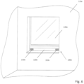
- Fig. 8 shows an embodiment of a system 100c which is similar to that shown in Fig. 7 In contrast to the execution of Fig. 7 However, the system 100c is as in Fig. 1b shown. This means that a first outlet 210c and a second inlet 310c are closer together. Otherwise, however, this is also an embodiment which is formed as part of a window frame 125c of a window 130c in a wall 110c.
- Fig. 9 shows an embodiment of a system 100d which is similar to that of Fig. 8 However, the system 100d is vertical, not like in Fig. 8 horizontally, installed in a window frame 125d of a window 130d.
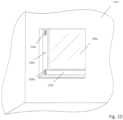
- Fig. 10 shows an embodiment of a system 100e which is similar to that of Fig. 9 However, in a modification, the System 100e is as in Fig. 1a shown. Accordingly, a first outlet 210e and a second inlet 310e are further apart from each other. Also in the embodiment of Fig. 10 the system is designed as part of a window frame 125e of a window 130e in a wall 110e.
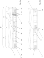
- Fig. 11a ) to c) show different representations of an embodiment of a system 100f according to the invention.
- Fig. 11a shows an external view of the system from a first side x
- Fig. 11b a sectional view along the line AA in Fig. 11a
- Fig. 11c External view of the system from a second side y, opposite the first.
- the 100f system is similar to the system of Fig. 1b The following description focuses on the differences.
- the axial fans 220f and 320f in system 100f are arranged so that their axes of rotation are turned out of the air flow by 45°. Such a fan arrangement further optimizes the flow to the heat exchanger 230f or 330f and leads to low power consumption of the fan.
- the present embodiment has sleeves 400f through which screws can be passed to attach the system to an adjacent wall.
- the sleeves serve to fix the components of the system 100f against each other.
- An example of a suitable sleeve is shown below in Fig. 13 shown.
- Fig. 12 a shows a rear view of an inner panel 500g suitable for the system 100f. It has two magnets 510g for attachment to the system 100f and a magnet 520g, the position of which can be detected by a Hall sensor (not shown here) arranged on the system 100f.
- the inner panel 500g has a first outlet 210g and a second inlet 310g.
- the arrangement of the inlet and the outlet along the longitudinal extension of the inner panel corresponds to the arrangement of the ventilation openings 280f and 380f of the system 100f in Fig. 11b ). In particular, it is asymmetrical with respect to the longitudinal extension of the installation profile.
- Fig. 12 b shows the effect of the inner panel on a section of the system 100f.
- the inner panel 500g is rotated here. If the inner panel 500g is rotated by 180° from its original position, in which the outlet 210g of the inner panel is above the ventilation opening 280g of the system 100f, the inner panel closes the system in conjunction with a web 270g.
- the web runs along an outside of a corpus 150f formed from a hollow profile, which is located behind the inner panel, in such a way that in this rotated arrangement of the inner panel no air can flow from the outlet 210g of the inner panel to the ventilation opening 280g in the corpus 150f.
- the Hall sensor detects the new position of the panel and thus makes it possible to switch off the ventilation system.
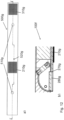
- Fig. 13 shows in three sub-figures 13a) to 13c) an embodiment of a sleeve 400h for a built-in profile, as it is used for example in the system 100f of Fig. 11 is shown.
- Fig. 13 a shows a longitudinal section of the sleeve 400h.
- the sleeve has a circumferential groove 410h at one lower end, into which a cable tie, for example, can be inserted to lock the sleeve to the installation profile.
- the sleeve 400h has a circumferential, bevelled edge 420h, with the help of which it can be arranged flush in a countersunk hole in the installation profile.
- Fig. 13b shows a cross-sectional view of a variant of the sleeve 400h in a cross-sectional plane near the lower end.
- the otherwise cylindrical sleeve has here has a circular inner cross-section, whereby the outer cross-section has a flattening 430h.
- a hole 440h in the area of the circumferential groove 410h at the level of the flattening serves to accommodate a locking pin.
- Fig. 13 c) shows a partial side view of this variant of the sleeve 400h, also in the area of its lower end.
Landscapes
- Engineering & Computer Science (AREA)
- Chemical & Material Sciences (AREA)
- Combustion & Propulsion (AREA)
- Mechanical Engineering (AREA)
- General Engineering & Computer Science (AREA)
- Life Sciences & Earth Sciences (AREA)
- Sustainable Development (AREA)
- Water Supply & Treatment (AREA)
- Hydrology & Water Resources (AREA)
- Civil Engineering (AREA)
- Environmental & Geological Engineering (AREA)
- Structural Engineering (AREA)
- Health & Medical Sciences (AREA)
- Chemical Kinetics & Catalysis (AREA)
- Electrochemistry (AREA)
- General Chemical & Material Sciences (AREA)
- Public Health (AREA)
- Organic Chemistry (AREA)
- Air-Conditioning Room Units, And Self-Contained Units In General (AREA)
- Ventilation (AREA)
- Building Environments (AREA)
- Duct Arrangements (AREA)
- Air-Flow Control Members (AREA)
Claims (11)
- Profilé d'encastrement (200) destiné à être monté sur un système mural dans une paroi de bâtiment (110), comprenant :- un espace interne de profilé qui est conçu comme un espace d'écoulement et qui comprend une entrée (240) et une sortie (210) ;- un matériau échangeur thermique (230), qui est disposé de façon à être traversé dans l'espace d'écoulement entre l'entrée (240) et la sortie (210) ;- un système de ventilation pour un transport par écoulement bidirectionnel à travers le matériau échangeur thermique, le système de ventilation comprenant exactement un ventilateur axial (220) qui peut être utilisé de manière bidirectionnelle et qui est disposé, en laissant une distance d'uniformisation, qui définit un espace d'uniformisation, à une certaine distance du matériau échangeur thermique (230) dans l'espace d'écoulement, dans lequeldans l'espace d'uniformisation, est disposé un dispositif d'uniformisation d'écoulement de façon à ce que, tout en évitant un écoulement insuffisant dans le matériau échangeur thermique du fait d'une zone morte du ventilateur axial, un flux d'air généré à travers le ventilateur axial s'écoule de manière uniformément répartie à travers le matériau échangeur thermique,
caractérisé en ce que
le ventilateur axial est disposé de façon à ce que son axe de rotation forme, avec le flux d'air, un angle entre 30° et 60°,. - Profilé d'encastrement (200) selon la revendication 1,
dans lequel la distance d'uniformisation est inférieure à 10 cm, plus particulièrement inférieur à 1 cm. - Profilé d'encastrement (200) selon l'une des revendications 1 à 2,
le ventilateur axial étant disposé entre le matériau échangeur thermique et l'entrée ou le ventilateur axial étant disposé entre le matériau échangeur thermique et la sortie. - Profilé d'encastrement (200) selon l'une des revendications précédentes, dans lequel le ventilateur axial comprend une roue de ventilateur dont la circonférence extérieure peut être décrite, dans au moins un plan perpendiculaire à l'axe du ventilateur, par un cercle et dans lequel la distance d'uniformisation est égal, avec un écart de 20 % maximum, plus particulièrement inférieur à 10 %, plus particulièrement est exactement égal au rayon du cercle.
- Profilé d'encastrement (200) selon l'une des revendications 1 à 4, dans lequel le ventilateur axial est disposé de façon à ce que son axe de rotation forme, avec le flux d'air, un angle de 45°.
- Profilé d'encastrement (200) selon l'une des revendications 1 à 5, dans lequel le matériau échangeur thermique se présente sous la forme d'une poudre ou de billes et est contenue dans une cassette ou dans lequel le matériau échangeur thermique est un matériau céramique, plus particulièrement avec une part d'oxyde métallique.
- Profilé d'encastrement (200) selon l'une des revendications 1 à 6,
qui comprend un diaphragme interne (500) qui comprend une ouverture de ventilation et qui est fixé de manière amovible au profilé d'encastrement, la sortie (210) étant disposée, dans une première position, au-dessus de l'ouverture de ventilation (280) du profilé d'encastrement et, dans une deuxième position, décalée de 180° par rapport à la première position tournée du diaphragme interne (500), l'ouverture de ventilation du profilé d'encastrement est obturée. - Profilé d'encastrement (200) selon la revendication 7,
qui disposé d'un aimant (520) monté de manière excentrée sur le diaphragme interne (500) ainsi que d'un capteur à effet Hall, qui peut détecter la position du diaphragme interne. - Système (100) pour la ventilation d'une pièce,qui comprend un profilé d'encastrement (200) selon l'une des revendications 1 à 8 ainsi qu'un profilé d'encastrement supplémentaire (300) selon l'une des revendications 1 à 8,dans lequel le profilé d'encastrement (200) et le profilé d'encastrement supplémentaire (300) sont montés de manière alternée à contre-courant.
- Système (100) selon la revendication 9,
dans lequel le profilé d'encastrement (200) et le profilé d'encastrement supplémentaire (300) sont reliés entre eux afin d'obtenir un profilé de ventilation. - Système (100) selon la revendication 10,
qui est disposé dans ou conçu comme un profilé adaptateur (120) d'une fenêtre (130) ou comme une partie d'un cadre de fenêtre (125).
Priority Applications (1)
| Application Number | Priority Date | Filing Date | Title |
|---|---|---|---|
| SI201231551T SI2739913T2 (sl) | 2011-08-03 | 2012-07-09 | Vgradni profil |
Applications Claiming Priority (3)
| Application Number | Priority Date | Filing Date | Title |
|---|---|---|---|
| DE202011104662U DE202011104662U1 (de) | 2011-08-03 | 2011-08-03 | Einbauprofil |
| DE102011080358A DE102011080358A1 (de) | 2011-08-03 | 2011-08-03 | Einbauprofil |
| PCT/EP2012/063434 WO2013017378A1 (fr) | 2011-08-03 | 2012-07-09 | Profilé de montage |
Publications (3)
| Publication Number | Publication Date |
|---|---|
| EP2739913A1 EP2739913A1 (fr) | 2014-06-11 |
| EP2739913B1 EP2739913B1 (fr) | 2018-12-26 |
| EP2739913B2 true EP2739913B2 (fr) | 2024-10-16 |
Family
ID=46508050
Family Applications (1)
| Application Number | Title | Priority Date | Filing Date |
|---|---|---|---|
| EP12734929.8A Active EP2739913B2 (fr) | 2011-08-03 | 2012-07-09 | Profilé de montage |
Country Status (9)
| Country | Link |
|---|---|
| US (1) | US10746422B2 (fr) |
| EP (1) | EP2739913B2 (fr) |
| JP (1) | JP2014521916A (fr) |
| CN (1) | CN103874889B (fr) |
| AU (1) | AU2012292291A1 (fr) |
| CA (1) | CA2843784A1 (fr) |
| DE (1) | DE202011104662U1 (fr) |
| SI (1) | SI2739913T2 (fr) |
| WO (1) | WO2013017378A1 (fr) |
Families Citing this family (10)
| Publication number | Priority date | Publication date | Assignee | Title |
|---|---|---|---|---|
| DE102012106253B3 (de) | 2012-05-14 | 2013-10-24 | Hautau Gmbh | Im Einbauzustand austauschbares Lüftungsgerät zum Lüften und zum Erhalt der regulären Verglasungsgröße |
| DE102012104198A1 (de) | 2012-05-14 | 2013-11-14 | Hautau Gmbh | Rahmenlüftungsgerät, Fensteranordnung und eingebautes Fenster mit Lüftungsgerät zum Lüften und zum Erhalt der regulären Verglasungsgröße und auch Rahmenmaße |
| DE202014100920U1 (de) | 2014-02-28 | 2014-04-17 | Tmp Fenster + Türen Gmbh | Rollladenführungsschiene mit integriertem Lüftungskanal |
| DE102014108852A1 (de) * | 2014-06-25 | 2016-01-21 | Manfred Lusch | Belüftungsvorrichtung |
| DE102014222824B4 (de) | 2014-11-07 | 2018-07-26 | LUNOS Lüftungstechnik GmbH für Raumluftsysteme | Lüftungsgerät mit Wärmerückgewinnung |
| BE1023751B1 (nl) | 2016-01-11 | 2017-07-11 | Renson Ventilation Nv | Ventilatie-inrichting |
| DE102016103950B4 (de) | 2016-03-04 | 2022-05-19 | Beck+Heun Gmbh | Anordnung zur Be- und Entlüftung von Räumen im Bereich eines Fensters |
| CN107687693A (zh) * | 2016-08-06 | 2018-02-13 | 赵乐 | 一种往复式节能通风机 |
| CN106642311B (zh) * | 2016-09-19 | 2022-05-27 | 珠海格力电器股份有限公司 | 空调器及其控制方法 |
| DE102022002364A1 (de) * | 2022-06-30 | 2024-01-04 | Talkpool AG | Dezentrale Fensterlüftungsvorrichtung |
Citations (9)
| Publication number | Priority date | Publication date | Assignee | Title |
|---|---|---|---|---|
| FR2509022A1 (fr) † | 1981-07-02 | 1983-01-07 | Hedstrom Stig | Procede et dispositifs pour ameliorer la recuperation de l'energie en utilisant en combinaison un ventilateur helicoidal reversible et un echangeur de chaleur |
| FR2583000A1 (fr) † | 1985-06-07 | 1986-12-12 | Sueddeutsche Kuehler Behr | Equipement de chauffage ou climatisation pour vehicules |
| US5375649A (en) † | 1991-12-23 | 1994-12-27 | Nilsen; Trond | Ventilation device |
| US5396783A (en) † | 1992-11-30 | 1995-03-14 | Goldstar Co., Ltd. | Cooling construction of an air conditioner outer unit |
| DE19730019C1 (de) † | 1997-07-12 | 1999-01-07 | Diels Manfred | Be- und Entlüftungsanlage mit regenerativer Wärmerückgewinnung |
| US7238105B2 (en) † | 2002-04-26 | 2007-07-03 | Oxyoell Holding B.V. | Dewpoint cooler designed as a frame or part thereof |
| WO2010085197A2 (fr) † | 2009-01-23 | 2010-07-29 | Swegon Ab | Unité de traitement de l'air à profil bas avec échangeur de chaleur tournant incliné |
| JP2010196945A (ja) † | 2009-02-24 | 2010-09-09 | Sanyo Electric Co Ltd | 室外ユニット |
| DE202010015615U1 (de) † | 2010-06-02 | 2011-03-03 | Gab Neumann Gmbh | Wärmetauscher |
Family Cites Families (32)
| Publication number | Priority date | Publication date | Assignee | Title |
|---|---|---|---|---|
| US2019351A (en) * | 1934-11-17 | 1935-10-29 | Gen Electric | Air conditioning apparatus |
| DE6937165U (de) | 1969-09-20 | 1970-03-19 | Friedhelm Laubkemeier | Raumluft - regenerator |
| US3738621A (en) * | 1969-11-10 | 1973-06-12 | Everkool Inc | Evaporative cooler |
| NO137706L (fr) | 1974-01-21 | |||
| CA1066964A (fr) * | 1976-09-28 | 1979-11-27 | Edna A. Dancy | Fabrication de caloducs en ceramique |
| GB8406501D0 (en) * | 1984-03-13 | 1984-04-18 | Environheat Ltd | Air conditioning apparatus |
| DE8516718U1 (de) | 1985-06-07 | 1990-08-30 | Behr GmbH & Co, 7000 Stuttgart | Heizungs- oder Klimaanlage für Kraftfahrzeuge |
| DE3613942A1 (de) | 1986-04-24 | 1987-10-29 | Erich Klawitter | Entlueftungs- und belueftungsanlage mit einem waermespeicher |
| DE3938259C1 (fr) * | 1989-11-17 | 1991-06-20 | Phototronics Solartechnik Gmbh, 8011 Putzbrunn, De | |
| US5050667A (en) | 1990-05-15 | 1991-09-24 | Erling Berner | Air ventilation and heat exchange apparatus |
| DE4022928C1 (fr) * | 1990-07-19 | 1992-02-06 | Webasto Ag Fahrzeugtechnik, 8035 Stockdorf, De | |
| DE4104423C2 (de) | 1991-02-14 | 1994-10-13 | Erich Klawitter | Entlüftungs- und Belüftungsanlage mit einem Wärmespeicher |
| DE4233529A1 (de) | 1992-10-06 | 1994-04-07 | Helge B Cohausz | Vorrichtung zum Be- und/oder Entlüften von Räumen |
| DE4241984A1 (de) * | 1992-12-12 | 1994-06-16 | Oleg Stolz | Regenerativer Wärmetauscher für gasförmige Medien, insbesondere Luftwärmetauscher für die Raumbelüftung von Gebäuden |
| DE9301812U1 (de) | 1993-02-10 | 1993-05-13 | Diels, Manfred, 5882 Meinerzhagen | Entlüftungs- und Belüftungsanlage mit einem Wärmespeicher |
| DE19638535C2 (de) | 1996-09-20 | 1999-05-20 | Diels Manfred | Be- und Entlüftungsanlage mit Wärmerückgewinnung |
| DE19811469A1 (de) | 1998-03-17 | 1999-09-30 | Rehfus Bernd | Apparat zur Be- und Entlüftung von Räumen mit einem regenerativen Wärmetauscher |
| US6342005B1 (en) * | 1999-09-30 | 2002-01-29 | Carrier Corporation | Active noise control for plug fan installations |
| JP2001289500A (ja) * | 2000-04-10 | 2001-10-19 | Koken Ltd | 一様空気流吹出装置 |
| DE20118672U1 (de) * | 2000-12-22 | 2002-02-14 | Diels, Manfred, 58540 Meinerzhagen | Be- und Entlüftungsanlage mit regenerativer Wärmerückgewinnung |
| CN2558914Y (zh) * | 2002-06-07 | 2003-07-02 | 杭州三以实业有限公司 | 一种通风设备 |
| US6662572B1 (en) * | 2002-12-30 | 2003-12-16 | The United States Of America As Represented By The Administrator Of The National Aeronautics And Space Administration | Solar powered automobile interior climate control system |
| DE102004011783B3 (de) * | 2004-03-09 | 2005-07-14 | Webasto Ag | Vorrichtung zur Belüftung und Kühlung eines Kraftfahrzeuginnenraumes |
| US7698906B2 (en) * | 2005-12-30 | 2010-04-20 | Nexajoule, Inc. | Sub-wet bulb evaporative chiller with pre-cooling of incoming air flow |
| US7768780B2 (en) * | 2006-06-19 | 2010-08-03 | Silicon Graphics International Corp. | Flow-through cooling for computer systems |
| US8413932B2 (en) * | 2010-04-10 | 2013-04-09 | Aerofex, Inc. | Peripheral control ejector |
| US7394654B2 (en) * | 2006-10-19 | 2008-07-01 | Cisco Technology, Inc. | Method and apparatus for providing thermal management in an electronic device |
| DE502008001254D1 (de) * | 2008-03-03 | 2010-10-14 | Schroff Gmbh | Gehäuse zur Aufnahme von elektronischen Steckbaugruppen |
| HU227348B1 (hu) * | 2008-06-02 | 2011-04-28 | Andras Csiha | Váltakozó áramlási irányú, decentralizált, hõvisszanyerõs szellõztetõberendezés |
| TWM346745U (en) * | 2008-07-25 | 2008-12-11 | Forcecon Technology Co Ltd | LED Lamp with heat-dissipation toward the terminal direction |
| US8085540B2 (en) | 2010-01-06 | 2011-12-27 | Oracle America, Inc. | Tandem fan assembly with airflow-straightening heat exchanger |
| US8581088B2 (en) * | 2011-12-03 | 2013-11-12 | Jeffery J. Bohl | Thermoelectric power generation apparatus and method |
-
2011
- 2011-08-03 DE DE202011104662U patent/DE202011104662U1/de not_active Expired - Lifetime
-
2012
- 2012-07-09 AU AU2012292291A patent/AU2012292291A1/en not_active Abandoned
- 2012-07-09 CN CN201280048169.3A patent/CN103874889B/zh active Active
- 2012-07-09 CA CA2843784A patent/CA2843784A1/fr not_active Abandoned
- 2012-07-09 SI SI201231551T patent/SI2739913T2/sl unknown
- 2012-07-09 JP JP2014523262A patent/JP2014521916A/ja active Pending
- 2012-07-09 EP EP12734929.8A patent/EP2739913B2/fr active Active
- 2012-07-09 WO PCT/EP2012/063434 patent/WO2013017378A1/fr not_active Ceased
- 2012-07-09 US US14/236,687 patent/US10746422B2/en active Active
Patent Citations (9)
| Publication number | Priority date | Publication date | Assignee | Title |
|---|---|---|---|---|
| FR2509022A1 (fr) † | 1981-07-02 | 1983-01-07 | Hedstrom Stig | Procede et dispositifs pour ameliorer la recuperation de l'energie en utilisant en combinaison un ventilateur helicoidal reversible et un echangeur de chaleur |
| FR2583000A1 (fr) † | 1985-06-07 | 1986-12-12 | Sueddeutsche Kuehler Behr | Equipement de chauffage ou climatisation pour vehicules |
| US5375649A (en) † | 1991-12-23 | 1994-12-27 | Nilsen; Trond | Ventilation device |
| US5396783A (en) † | 1992-11-30 | 1995-03-14 | Goldstar Co., Ltd. | Cooling construction of an air conditioner outer unit |
| DE19730019C1 (de) † | 1997-07-12 | 1999-01-07 | Diels Manfred | Be- und Entlüftungsanlage mit regenerativer Wärmerückgewinnung |
| US7238105B2 (en) † | 2002-04-26 | 2007-07-03 | Oxyoell Holding B.V. | Dewpoint cooler designed as a frame or part thereof |
| WO2010085197A2 (fr) † | 2009-01-23 | 2010-07-29 | Swegon Ab | Unité de traitement de l'air à profil bas avec échangeur de chaleur tournant incliné |
| JP2010196945A (ja) † | 2009-02-24 | 2010-09-09 | Sanyo Electric Co Ltd | 室外ユニット |
| DE202010015615U1 (de) † | 2010-06-02 | 2011-03-03 | Gab Neumann Gmbh | Wärmetauscher |
Also Published As
| Publication number | Publication date |
|---|---|
| CA2843784A1 (fr) | 2013-02-07 |
| SI2739913T1 (sl) | 2019-04-30 |
| EP2739913A1 (fr) | 2014-06-11 |
| WO2013017378A1 (fr) | 2013-02-07 |
| EP2739913B1 (fr) | 2018-12-26 |
| US10746422B2 (en) | 2020-08-18 |
| AU2012292291A1 (en) | 2014-02-20 |
| SI2739913T2 (sl) | 2025-07-31 |
| CN103874889B (zh) | 2017-08-22 |
| US20140162543A1 (en) | 2014-06-12 |
| CN103874889A (zh) | 2014-06-18 |
| JP2014521916A (ja) | 2014-08-28 |
| DE202011104662U1 (de) | 2011-12-05 |
Similar Documents
| Publication | Publication Date | Title |
|---|---|---|
| EP2739913B2 (fr) | Profilé de montage | |
| DE102011080358A1 (de) | Einbauprofil | |
| AT512198B1 (de) | Fenster | |
| EP2894412B1 (fr) | Appareil d'aération destiné à l'aération intérieure de bâtiments | |
| EP3168544A1 (fr) | Dispositif d'aération | |
| DE3043783A1 (de) | Schall- und waermeisolierendes verbundfenster mit verstellbarer schalldaemmlueftung | |
| WO2013171075A1 (fr) | Système de joint de porte | |
| DE60114624T2 (de) | Kombination aus fensterjalousie und sicherheitsladen | |
| WO2023089137A1 (fr) | Air de circulation et système de module d'air de circulation | |
| DE19837162A1 (de) | Fenster- und Türprofil zum Rückgewinnen von Lüftungswärme | |
| EP3670813A1 (fr) | Fenetre ou porte avec un dormant et un panneau coulissant | |
| EP1411303A1 (fr) | Elément de régulation de la température d'une enceinte et son agencement | |
| DE3233499A1 (de) | Solarpaneele insbesondere fuer aussenfenster | |
| EP1624258A2 (fr) | Dispositif pour la ventilation d'un local et module de montage pour la ventilation d'un local | |
| EP0692686A2 (fr) | Façade à double paroi | |
| EP0990859A2 (fr) | Dispositif d'amenée et évacuation d'air | |
| WO2013041224A2 (fr) | Châssis dormant d'une fenêtre à dispositif de ventilation intégré et dispositif de ventilation pour ledit châssis | |
| DE3341827A1 (de) | Lueftungssystem fuer die raeume von gebaeuden | |
| DE3030536C2 (de) | Brüstungselement zum Einbau in Fassaden | |
| EP0663573B1 (fr) | Façade à double paroi | |
| DE9407112U1 (de) | Kompakt-Luftschleieranlage | |
| EP1519120A1 (fr) | Clapet coupe-feu à actionnement éléctrique | |
| DE202016008451U1 (de) | Vorrichtung zur Be- und Entlüftung von Räumen im Bereich eines Fensters | |
| DE4437849C2 (de) | Verwendung und Ausbildung eines Dreh- und/oder Kippflügels | |
| CH720961A2 (de) | Lüftungseinrichtung |
Legal Events
| Date | Code | Title | Description |
|---|---|---|---|
| PUAI | Public reference made under article 153(3) epc to a published international application that has entered the european phase |
Free format text: ORIGINAL CODE: 0009012 |
|
| 17P | Request for examination filed |
Effective date: 20140303 |
|
| AK | Designated contracting states |
Kind code of ref document: A1 Designated state(s): AL AT BE BG CH CY CZ DE DK EE ES FI FR GB GR HR HU IE IS IT LI LT LU LV MC MK MT NL NO PL PT RO RS SE SI SK SM TR |
|
| DAX | Request for extension of the european patent (deleted) | ||
| STAA | Information on the status of an ep patent application or granted ep patent |
Free format text: STATUS: EXAMINATION IS IN PROGRESS |
|
| 17Q | First examination report despatched |
Effective date: 20170421 |
|
| RIC1 | Information provided on ipc code assigned before grant |
Ipc: F24F 7/08 20060101ALI20180619BHEP Ipc: F24F 12/00 20060101AFI20180619BHEP Ipc: F24F 13/30 20060101ALI20180619BHEP Ipc: F24F 7/10 20060101ALI20180619BHEP Ipc: F24F 5/00 20060101ALI20180619BHEP |
|
| GRAP | Despatch of communication of intention to grant a patent |
Free format text: ORIGINAL CODE: EPIDOSNIGR1 |
|
| STAA | Information on the status of an ep patent application or granted ep patent |
Free format text: STATUS: GRANT OF PATENT IS INTENDED |
|
| GRAS | Grant fee paid |
Free format text: ORIGINAL CODE: EPIDOSNIGR3 |
|
| INTG | Intention to grant announced |
Effective date: 20181023 |
|
| GRAA | (expected) grant |
Free format text: ORIGINAL CODE: 0009210 |
|
| STAA | Information on the status of an ep patent application or granted ep patent |
Free format text: STATUS: THE PATENT HAS BEEN GRANTED |
|
| AK | Designated contracting states |
Kind code of ref document: B1 Designated state(s): AL AT BE BG CH CY CZ DE DK EE ES FI FR GB GR HR HU IE IS IT LI LT LU LV MC MK MT NL NO PL PT RO RS SE SI SK SM TR |
|
| REG | Reference to a national code |
Ref country code: GB Ref legal event code: FG4D Free format text: NOT ENGLISH |
|
| REG | Reference to a national code |
Ref country code: CH Ref legal event code: EP |
|
| REG | Reference to a national code |
Ref country code: AT Ref legal event code: REF Ref document number: 1081946 Country of ref document: AT Kind code of ref document: T Effective date: 20190115 |
|
| REG | Reference to a national code |
Ref country code: DE Ref legal event code: R096 Ref document number: 502012014057 Country of ref document: DE |
|
| REG | Reference to a national code |
Ref country code: IE Ref legal event code: FG4D Free format text: LANGUAGE OF EP DOCUMENT: GERMAN |
|
| REG | Reference to a national code |
Ref country code: SE Ref legal event code: TRGR |
|
| PG25 | Lapsed in a contracting state [announced via postgrant information from national office to epo] |
Ref country code: HR Free format text: LAPSE BECAUSE OF FAILURE TO SUBMIT A TRANSLATION OF THE DESCRIPTION OR TO PAY THE FEE WITHIN THE PRESCRIBED TIME-LIMIT Effective date: 20181226 Ref country code: BG Free format text: LAPSE BECAUSE OF FAILURE TO SUBMIT A TRANSLATION OF THE DESCRIPTION OR TO PAY THE FEE WITHIN THE PRESCRIBED TIME-LIMIT Effective date: 20190326 Ref country code: FI Free format text: LAPSE BECAUSE OF FAILURE TO SUBMIT A TRANSLATION OF THE DESCRIPTION OR TO PAY THE FEE WITHIN THE PRESCRIBED TIME-LIMIT Effective date: 20181226 Ref country code: LT Free format text: LAPSE BECAUSE OF FAILURE TO SUBMIT A TRANSLATION OF THE DESCRIPTION OR TO PAY THE FEE WITHIN THE PRESCRIBED TIME-LIMIT Effective date: 20181226 Ref country code: LV Free format text: LAPSE BECAUSE OF FAILURE TO SUBMIT A TRANSLATION OF THE DESCRIPTION OR TO PAY THE FEE WITHIN THE PRESCRIBED TIME-LIMIT Effective date: 20181226 |
|
| REG | Reference to a national code |
Ref country code: NL Ref legal event code: MP Effective date: 20181226 |
|
| REG | Reference to a national code |
Ref country code: LT Ref legal event code: MG4D |
|
| REG | Reference to a national code |
Ref country code: NO Ref legal event code: T2 Effective date: 20181226 |
|
| PG25 | Lapsed in a contracting state [announced via postgrant information from national office to epo] |
Ref country code: AL Free format text: LAPSE BECAUSE OF FAILURE TO SUBMIT A TRANSLATION OF THE DESCRIPTION OR TO PAY THE FEE WITHIN THE PRESCRIBED TIME-LIMIT Effective date: 20181226 Ref country code: RS Free format text: LAPSE BECAUSE OF FAILURE TO SUBMIT A TRANSLATION OF THE DESCRIPTION OR TO PAY THE FEE WITHIN THE PRESCRIBED TIME-LIMIT Effective date: 20181226 Ref country code: GR Free format text: LAPSE BECAUSE OF FAILURE TO SUBMIT A TRANSLATION OF THE DESCRIPTION OR TO PAY THE FEE WITHIN THE PRESCRIBED TIME-LIMIT Effective date: 20190327 |
|
| PG25 | Lapsed in a contracting state [announced via postgrant information from national office to epo] |
Ref country code: NL Free format text: LAPSE BECAUSE OF FAILURE TO SUBMIT A TRANSLATION OF THE DESCRIPTION OR TO PAY THE FEE WITHIN THE PRESCRIBED TIME-LIMIT Effective date: 20181226 |
|
| PG25 | Lapsed in a contracting state [announced via postgrant information from national office to epo] |
Ref country code: PT Free format text: LAPSE BECAUSE OF FAILURE TO SUBMIT A TRANSLATION OF THE DESCRIPTION OR TO PAY THE FEE WITHIN THE PRESCRIBED TIME-LIMIT Effective date: 20190426 Ref country code: CZ Free format text: LAPSE BECAUSE OF FAILURE TO SUBMIT A TRANSLATION OF THE DESCRIPTION OR TO PAY THE FEE WITHIN THE PRESCRIBED TIME-LIMIT Effective date: 20181226 Ref country code: PL Free format text: LAPSE BECAUSE OF FAILURE TO SUBMIT A TRANSLATION OF THE DESCRIPTION OR TO PAY THE FEE WITHIN THE PRESCRIBED TIME-LIMIT Effective date: 20181226 Ref country code: ES Free format text: LAPSE BECAUSE OF FAILURE TO SUBMIT A TRANSLATION OF THE DESCRIPTION OR TO PAY THE FEE WITHIN THE PRESCRIBED TIME-LIMIT Effective date: 20181226 |
|
| PG25 | Lapsed in a contracting state [announced via postgrant information from national office to epo] |
Ref country code: SK Free format text: LAPSE BECAUSE OF FAILURE TO SUBMIT A TRANSLATION OF THE DESCRIPTION OR TO PAY THE FEE WITHIN THE PRESCRIBED TIME-LIMIT Effective date: 20181226 Ref country code: EE Free format text: LAPSE BECAUSE OF FAILURE TO SUBMIT A TRANSLATION OF THE DESCRIPTION OR TO PAY THE FEE WITHIN THE PRESCRIBED TIME-LIMIT Effective date: 20181226 Ref country code: SM Free format text: LAPSE BECAUSE OF FAILURE TO SUBMIT A TRANSLATION OF THE DESCRIPTION OR TO PAY THE FEE WITHIN THE PRESCRIBED TIME-LIMIT Effective date: 20181226 Ref country code: RO Free format text: LAPSE BECAUSE OF FAILURE TO SUBMIT A TRANSLATION OF THE DESCRIPTION OR TO PAY THE FEE WITHIN THE PRESCRIBED TIME-LIMIT Effective date: 20181226 Ref country code: IS Free format text: LAPSE BECAUSE OF FAILURE TO SUBMIT A TRANSLATION OF THE DESCRIPTION OR TO PAY THE FEE WITHIN THE PRESCRIBED TIME-LIMIT Effective date: 20190426 |
|
| REG | Reference to a national code |
Ref country code: DE Ref legal event code: R026 Ref document number: 502012014057 Country of ref document: DE |
|
| PLBI | Opposition filed |
Free format text: ORIGINAL CODE: 0009260 |
|
| PLAX | Notice of opposition and request to file observation + time limit sent |
Free format text: ORIGINAL CODE: EPIDOSNOBS2 |
|
| PG25 | Lapsed in a contracting state [announced via postgrant information from national office to epo] |
Ref country code: DK Free format text: LAPSE BECAUSE OF FAILURE TO SUBMIT A TRANSLATION OF THE DESCRIPTION OR TO PAY THE FEE WITHIN THE PRESCRIBED TIME-LIMIT Effective date: 20181226 |
|
| 26 | Opposition filed |
Opponent name: MARLEY DEUTSCHLAND GMBH Effective date: 20190926 Opponent name: HELIOS VENTILATOREN GMBH & CO. KG Effective date: 20190925 |
|
| PLBB | Reply of patent proprietor to notice(s) of opposition received |
Free format text: ORIGINAL CODE: EPIDOSNOBS3 |
|
| PG25 | Lapsed in a contracting state [announced via postgrant information from national office to epo] |
Ref country code: MC Free format text: LAPSE BECAUSE OF FAILURE TO SUBMIT A TRANSLATION OF THE DESCRIPTION OR TO PAY THE FEE WITHIN THE PRESCRIBED TIME-LIMIT Effective date: 20181226 |
|
| GBPC | Gb: european patent ceased through non-payment of renewal fee |
Effective date: 20190709 |
|
| PG25 | Lapsed in a contracting state [announced via postgrant information from national office to epo] |
Ref country code: TR Free format text: LAPSE BECAUSE OF FAILURE TO SUBMIT A TRANSLATION OF THE DESCRIPTION OR TO PAY THE FEE WITHIN THE PRESCRIBED TIME-LIMIT Effective date: 20181226 |
|
| REG | Reference to a national code |
Ref country code: BE Ref legal event code: MM Effective date: 20190731 |
|
| PG25 | Lapsed in a contracting state [announced via postgrant information from national office to epo] |
Ref country code: GB Free format text: LAPSE BECAUSE OF NON-PAYMENT OF DUE FEES Effective date: 20190709 |
|
| PG25 | Lapsed in a contracting state [announced via postgrant information from national office to epo] |
Ref country code: LU Free format text: LAPSE BECAUSE OF NON-PAYMENT OF DUE FEES Effective date: 20190709 Ref country code: BE Free format text: LAPSE BECAUSE OF NON-PAYMENT OF DUE FEES Effective date: 20190731 |
|
| PG25 | Lapsed in a contracting state [announced via postgrant information from national office to epo] |
Ref country code: IE Free format text: LAPSE BECAUSE OF NON-PAYMENT OF DUE FEES Effective date: 20190709 |
|
| PG25 | Lapsed in a contracting state [announced via postgrant information from national office to epo] |
Ref country code: CY Free format text: LAPSE BECAUSE OF FAILURE TO SUBMIT A TRANSLATION OF THE DESCRIPTION OR TO PAY THE FEE WITHIN THE PRESCRIBED TIME-LIMIT Effective date: 20181226 |
|
| PG25 | Lapsed in a contracting state [announced via postgrant information from national office to epo] |
Ref country code: MT Free format text: LAPSE BECAUSE OF FAILURE TO SUBMIT A TRANSLATION OF THE DESCRIPTION OR TO PAY THE FEE WITHIN THE PRESCRIBED TIME-LIMIT Effective date: 20181226 Ref country code: HU Free format text: LAPSE BECAUSE OF FAILURE TO SUBMIT A TRANSLATION OF THE DESCRIPTION OR TO PAY THE FEE WITHIN THE PRESCRIBED TIME-LIMIT; INVALID AB INITIO Effective date: 20120709 |
|
| APBM | Appeal reference recorded |
Free format text: ORIGINAL CODE: EPIDOSNREFNO |
|
| APBP | Date of receipt of notice of appeal recorded |
Free format text: ORIGINAL CODE: EPIDOSNNOA2O |
|
| APAH | Appeal reference modified |
Free format text: ORIGINAL CODE: EPIDOSCREFNO |
|
| APBQ | Date of receipt of statement of grounds of appeal recorded |
Free format text: ORIGINAL CODE: EPIDOSNNOA3O |
|
| REG | Reference to a national code |
Ref country code: DE Ref legal event code: R081 Ref document number: 502012014057 Country of ref document: DE Owner name: LUNOS LUEFTUNGSTECHNIK GMBH & CO. KG FUER RAUM, DE Free format text: FORMER OWNER: LUNOS LUEFTUNGSTECHNIK GMBH FUER RAUMLUFTSYSTEME, 13593 BERLIN, DE |
|
| PG25 | Lapsed in a contracting state [announced via postgrant information from national office to epo] |
Ref country code: MK Free format text: LAPSE BECAUSE OF FAILURE TO SUBMIT A TRANSLATION OF THE DESCRIPTION OR TO PAY THE FEE WITHIN THE PRESCRIBED TIME-LIMIT Effective date: 20181226 |
|
| P01 | Opt-out of the competence of the unified patent court (upc) registered |
Effective date: 20230519 |
|
| RAP4 | Party data changed (patent owner data changed or rights of a patent transferred) |
Owner name: LUNOS LUEFTUNGSTECHNIK GMBH & CO. KG FUER RAUMLUFTSYSTEME |
|
| APBU | Appeal procedure closed |
Free format text: ORIGINAL CODE: EPIDOSNNOA9O |
|
| PUAH | Patent maintained in amended form |
Free format text: ORIGINAL CODE: 0009272 |
|
| STAA | Information on the status of an ep patent application or granted ep patent |
Free format text: STATUS: PATENT MAINTAINED AS AMENDED |
|
| 27A | Patent maintained in amended form |
Effective date: 20241016 |
|
| AK | Designated contracting states |
Kind code of ref document: B2 Designated state(s): AL AT BE BG CH CY CZ DE DK EE ES FI FR GB GR HR HU IE IS IT LI LT LU LV MC MK MT NL NO PL PT RO RS SE SI SK SM TR |
|
| REG | Reference to a national code |
Ref country code: DE Ref legal event code: R102 Ref document number: 502012014057 Country of ref document: DE |
|
| REG | Reference to a national code |
Ref country code: SE Ref legal event code: RPEO |
|
| PGFP | Annual fee paid to national office [announced via postgrant information from national office to epo] |
Ref country code: SI Payment date: 20250630 Year of fee payment: 14 |
|
| PGFP | Annual fee paid to national office [announced via postgrant information from national office to epo] |
Ref country code: DE Payment date: 20250811 Year of fee payment: 14 |
|
| PGFP | Annual fee paid to national office [announced via postgrant information from national office to epo] |
Ref country code: NO Payment date: 20250722 Year of fee payment: 14 |
|
| PGFP | Annual fee paid to national office [announced via postgrant information from national office to epo] |
Ref country code: IT Payment date: 20250731 Year of fee payment: 14 |
|
| PGFP | Annual fee paid to national office [announced via postgrant information from national office to epo] |
Ref country code: FR Payment date: 20250723 Year of fee payment: 14 Ref country code: AT Payment date: 20250721 Year of fee payment: 14 |
|
| PGFP | Annual fee paid to national office [announced via postgrant information from national office to epo] |
Ref country code: CH Payment date: 20250801 Year of fee payment: 14 Ref country code: SE Payment date: 20250723 Year of fee payment: 14 |