EP2739896B1 - Insulating block for manufacturing a tank wall - Google Patents
Insulating block for manufacturing a tank wall Download PDFInfo
- Publication number
- EP2739896B1 EP2739896B1 EP12750432.2A EP12750432A EP2739896B1 EP 2739896 B1 EP2739896 B1 EP 2739896B1 EP 12750432 A EP12750432 A EP 12750432A EP 2739896 B1 EP2739896 B1 EP 2739896B1
- Authority
- EP
- European Patent Office
- Prior art keywords
- insulating
- pillars
- tank
- insulating block
- ship
- Prior art date
- Legal status (The legal status is an assumption and is not a legal conclusion. Google has not performed a legal analysis and makes no representation as to the accuracy of the status listed.)
- Not-in-force
Links
- 238000004519 manufacturing process Methods 0.000 title claims description 9
- 239000012528 membrane Substances 0.000 claims description 56
- 125000006850 spacer group Chemical group 0.000 claims description 41
- 230000004888 barrier function Effects 0.000 claims description 34
- 230000002787 reinforcement Effects 0.000 claims description 21
- 238000003860 storage Methods 0.000 claims description 12
- 239000012263 liquid product Substances 0.000 claims description 9
- 238000000034 method Methods 0.000 claims description 2
- 239000002023 wood Substances 0.000 claims description 2
- 239000011810 insulating material Substances 0.000 description 27
- 239000006260 foam Substances 0.000 description 17
- 229920000642 polymer Polymers 0.000 description 10
- 230000000717 retained effect Effects 0.000 description 10
- 239000007789 gas Substances 0.000 description 6
- 238000009434 installation Methods 0.000 description 6
- 238000003466 welding Methods 0.000 description 5
- 229920005830 Polyurethane Foam Polymers 0.000 description 4
- 229910000831 Steel Inorganic materials 0.000 description 4
- 238000009413 insulation Methods 0.000 description 4
- 239000000463 material Substances 0.000 description 4
- 239000011496 polyurethane foam Substances 0.000 description 4
- 239000004800 polyvinyl chloride Substances 0.000 description 4
- 239000010959 steel Substances 0.000 description 4
- 238000005452 bending Methods 0.000 description 3
- 230000006835 compression Effects 0.000 description 3
- 238000007906 compression Methods 0.000 description 3
- 239000002184 metal Substances 0.000 description 3
- 229910052751 metal Inorganic materials 0.000 description 3
- 239000011120 plywood Substances 0.000 description 3
- IJGRMHOSHXDMSA-UHFFFAOYSA-N Atomic nitrogen Chemical compound N#N IJGRMHOSHXDMSA-UHFFFAOYSA-N 0.000 description 2
- XEEYBQQBJWHFJM-UHFFFAOYSA-N Iron Chemical compound [Fe] XEEYBQQBJWHFJM-UHFFFAOYSA-N 0.000 description 2
- 241001639412 Verres Species 0.000 description 2
- 239000007788 liquid Substances 0.000 description 2
- VNWKTOKETHGBQD-UHFFFAOYSA-N methane Chemical compound C VNWKTOKETHGBQD-UHFFFAOYSA-N 0.000 description 2
- 229920000915 polyvinyl chloride Polymers 0.000 description 2
- 238000004080 punching Methods 0.000 description 2
- 241000195940 Bryophyta Species 0.000 description 1
- 230000005540 biological transmission Effects 0.000 description 1
- 239000000969 carrier Substances 0.000 description 1
- 239000002131 composite material Substances 0.000 description 1
- 238000013016 damping Methods 0.000 description 1
- 238000009826 distribution Methods 0.000 description 1
- 239000000835 fiber Substances 0.000 description 1
- 239000011152 fibreglass Substances 0.000 description 1
- 239000012530 fluid Substances 0.000 description 1
- 239000011491 glass wool Substances 0.000 description 1
- 238000002347 injection Methods 0.000 description 1
- 239000007924 injection Substances 0.000 description 1
- 239000012212 insulator Substances 0.000 description 1
- 229910052742 iron Inorganic materials 0.000 description 1
- 238000002955 isolation Methods 0.000 description 1
- 235000011929 mousse Nutrition 0.000 description 1
- 229910052757 nitrogen Inorganic materials 0.000 description 1
- 238000012856 packing Methods 0.000 description 1
- 229910001562 pearlite Inorganic materials 0.000 description 1
- 235000019362 perlite Nutrition 0.000 description 1
- 239000010451 perlite Substances 0.000 description 1
- 238000009417 prefabrication Methods 0.000 description 1
- 230000003014 reinforcing effect Effects 0.000 description 1
- 238000005096 rolling process Methods 0.000 description 1
- 230000035939 shock Effects 0.000 description 1
- 239000000243 solution Substances 0.000 description 1
- 230000003068 static effect Effects 0.000 description 1
- XLYOFNOQVPJJNP-UHFFFAOYSA-N water Substances O XLYOFNOQVPJJNP-UHFFFAOYSA-N 0.000 description 1
- 238000004078 waterproofing Methods 0.000 description 1
Images


Classifications
-
- F—MECHANICAL ENGINEERING; LIGHTING; HEATING; WEAPONS; BLASTING
- F17—STORING OR DISTRIBUTING GASES OR LIQUIDS
- F17C—VESSELS FOR CONTAINING OR STORING COMPRESSED, LIQUEFIED OR SOLIDIFIED GASES; FIXED-CAPACITY GAS-HOLDERS; FILLING VESSELS WITH, OR DISCHARGING FROM VESSELS, COMPRESSED, LIQUEFIED, OR SOLIDIFIED GASES
- F17C3/00—Vessels not under pressure
- F17C3/02—Vessels not under pressure with provision for thermal insulation
- F17C3/025—Bulk storage in barges or on ships
- F17C3/027—Wallpanels for so-called membrane tanks
-
- F—MECHANICAL ENGINEERING; LIGHTING; HEATING; WEAPONS; BLASTING
- F17—STORING OR DISTRIBUTING GASES OR LIQUIDS
- F17C—VESSELS FOR CONTAINING OR STORING COMPRESSED, LIQUEFIED OR SOLIDIFIED GASES; FIXED-CAPACITY GAS-HOLDERS; FILLING VESSELS WITH, OR DISCHARGING FROM VESSELS, COMPRESSED, LIQUEFIED, OR SOLIDIFIED GASES
- F17C2201/00—Vessel construction, in particular geometry, arrangement or size
- F17C2201/01—Shape
- F17C2201/0147—Shape complex
- F17C2201/0157—Polygonal
-
- F—MECHANICAL ENGINEERING; LIGHTING; HEATING; WEAPONS; BLASTING
- F17—STORING OR DISTRIBUTING GASES OR LIQUIDS
- F17C—VESSELS FOR CONTAINING OR STORING COMPRESSED, LIQUEFIED OR SOLIDIFIED GASES; FIXED-CAPACITY GAS-HOLDERS; FILLING VESSELS WITH, OR DISCHARGING FROM VESSELS, COMPRESSED, LIQUEFIED, OR SOLIDIFIED GASES
- F17C2201/00—Vessel construction, in particular geometry, arrangement or size
- F17C2201/05—Size
- F17C2201/052—Size large (>1000 m3)
-
- F—MECHANICAL ENGINEERING; LIGHTING; HEATING; WEAPONS; BLASTING
- F17—STORING OR DISTRIBUTING GASES OR LIQUIDS
- F17C—VESSELS FOR CONTAINING OR STORING COMPRESSED, LIQUEFIED OR SOLIDIFIED GASES; FIXED-CAPACITY GAS-HOLDERS; FILLING VESSELS WITH, OR DISCHARGING FROM VESSELS, COMPRESSED, LIQUEFIED, OR SOLIDIFIED GASES
- F17C2203/00—Vessel construction, in particular walls or details thereof
- F17C2203/03—Thermal insulations
- F17C2203/0304—Thermal insulations by solid means
- F17C2203/0329—Foam
- F17C2203/0333—Polyurethane
-
- F—MECHANICAL ENGINEERING; LIGHTING; HEATING; WEAPONS; BLASTING
- F17—STORING OR DISTRIBUTING GASES OR LIQUIDS
- F17C—VESSELS FOR CONTAINING OR STORING COMPRESSED, LIQUEFIED OR SOLIDIFIED GASES; FIXED-CAPACITY GAS-HOLDERS; FILLING VESSELS WITH, OR DISCHARGING FROM VESSELS, COMPRESSED, LIQUEFIED, OR SOLIDIFIED GASES
- F17C2203/00—Vessel construction, in particular walls or details thereof
- F17C2203/03—Thermal insulations
- F17C2203/0304—Thermal insulations by solid means
- F17C2203/0337—Granular
- F17C2203/0341—Perlite
-
- F—MECHANICAL ENGINEERING; LIGHTING; HEATING; WEAPONS; BLASTING
- F17—STORING OR DISTRIBUTING GASES OR LIQUIDS
- F17C—VESSELS FOR CONTAINING OR STORING COMPRESSED, LIQUEFIED OR SOLIDIFIED GASES; FIXED-CAPACITY GAS-HOLDERS; FILLING VESSELS WITH, OR DISCHARGING FROM VESSELS, COMPRESSED, LIQUEFIED, OR SOLIDIFIED GASES
- F17C2203/00—Vessel construction, in particular walls or details thereof
- F17C2203/03—Thermal insulations
- F17C2203/0304—Thermal insulations by solid means
- F17C2203/0354—Wood
-
- F—MECHANICAL ENGINEERING; LIGHTING; HEATING; WEAPONS; BLASTING
- F17—STORING OR DISTRIBUTING GASES OR LIQUIDS
- F17C—VESSELS FOR CONTAINING OR STORING COMPRESSED, LIQUEFIED OR SOLIDIFIED GASES; FIXED-CAPACITY GAS-HOLDERS; FILLING VESSELS WITH, OR DISCHARGING FROM VESSELS, COMPRESSED, LIQUEFIED, OR SOLIDIFIED GASES
- F17C2203/00—Vessel construction, in particular walls or details thereof
- F17C2203/03—Thermal insulations
- F17C2203/0304—Thermal insulations by solid means
- F17C2203/0358—Thermal insulations by solid means in form of panels
-
- F—MECHANICAL ENGINEERING; LIGHTING; HEATING; WEAPONS; BLASTING
- F17—STORING OR DISTRIBUTING GASES OR LIQUIDS
- F17C—VESSELS FOR CONTAINING OR STORING COMPRESSED, LIQUEFIED OR SOLIDIFIED GASES; FIXED-CAPACITY GAS-HOLDERS; FILLING VESSELS WITH, OR DISCHARGING FROM VESSELS, COMPRESSED, LIQUEFIED, OR SOLIDIFIED GASES
- F17C2203/00—Vessel construction, in particular walls or details thereof
- F17C2203/06—Materials for walls or layers thereof; Properties or structures of walls or their materials
- F17C2203/0602—Wall structures; Special features thereof
- F17C2203/0612—Wall structures
- F17C2203/0626—Multiple walls
- F17C2203/0631—Three or more walls
-
- F—MECHANICAL ENGINEERING; LIGHTING; HEATING; WEAPONS; BLASTING
- F17—STORING OR DISTRIBUTING GASES OR LIQUIDS
- F17C—VESSELS FOR CONTAINING OR STORING COMPRESSED, LIQUEFIED OR SOLIDIFIED GASES; FIXED-CAPACITY GAS-HOLDERS; FILLING VESSELS WITH, OR DISCHARGING FROM VESSELS, COMPRESSED, LIQUEFIED, OR SOLIDIFIED GASES
- F17C2221/00—Handled fluid, in particular type of fluid
- F17C2221/03—Mixtures
- F17C2221/032—Hydrocarbons
- F17C2221/033—Methane, e.g. natural gas, CNG, LNG, GNL, GNC, PLNG
-
- F—MECHANICAL ENGINEERING; LIGHTING; HEATING; WEAPONS; BLASTING
- F17—STORING OR DISTRIBUTING GASES OR LIQUIDS
- F17C—VESSELS FOR CONTAINING OR STORING COMPRESSED, LIQUEFIED OR SOLIDIFIED GASES; FIXED-CAPACITY GAS-HOLDERS; FILLING VESSELS WITH, OR DISCHARGING FROM VESSELS, COMPRESSED, LIQUEFIED, OR SOLIDIFIED GASES
- F17C2223/00—Handled fluid before transfer, i.e. state of fluid when stored in the vessel or before transfer from the vessel
- F17C2223/01—Handled fluid before transfer, i.e. state of fluid when stored in the vessel or before transfer from the vessel characterised by the phase
- F17C2223/0146—Two-phase
- F17C2223/0153—Liquefied gas, e.g. LPG, GPL
- F17C2223/0161—Liquefied gas, e.g. LPG, GPL cryogenic, e.g. LNG, GNL, PLNG
-
- F—MECHANICAL ENGINEERING; LIGHTING; HEATING; WEAPONS; BLASTING
- F17—STORING OR DISTRIBUTING GASES OR LIQUIDS
- F17C—VESSELS FOR CONTAINING OR STORING COMPRESSED, LIQUEFIED OR SOLIDIFIED GASES; FIXED-CAPACITY GAS-HOLDERS; FILLING VESSELS WITH, OR DISCHARGING FROM VESSELS, COMPRESSED, LIQUEFIED, OR SOLIDIFIED GASES
- F17C2223/00—Handled fluid before transfer, i.e. state of fluid when stored in the vessel or before transfer from the vessel
- F17C2223/03—Handled fluid before transfer, i.e. state of fluid when stored in the vessel or before transfer from the vessel characterised by the pressure level
- F17C2223/033—Small pressure, e.g. for liquefied gas
-
- F—MECHANICAL ENGINEERING; LIGHTING; HEATING; WEAPONS; BLASTING
- F17—STORING OR DISTRIBUTING GASES OR LIQUIDS
- F17C—VESSELS FOR CONTAINING OR STORING COMPRESSED, LIQUEFIED OR SOLIDIFIED GASES; FIXED-CAPACITY GAS-HOLDERS; FILLING VESSELS WITH, OR DISCHARGING FROM VESSELS, COMPRESSED, LIQUEFIED, OR SOLIDIFIED GASES
- F17C2260/00—Purposes of gas storage and gas handling
- F17C2260/01—Improving mechanical properties or manufacturing
- F17C2260/011—Improving strength
-
- F—MECHANICAL ENGINEERING; LIGHTING; HEATING; WEAPONS; BLASTING
- F17—STORING OR DISTRIBUTING GASES OR LIQUIDS
- F17C—VESSELS FOR CONTAINING OR STORING COMPRESSED, LIQUEFIED OR SOLIDIFIED GASES; FIXED-CAPACITY GAS-HOLDERS; FILLING VESSELS WITH, OR DISCHARGING FROM VESSELS, COMPRESSED, LIQUEFIED, OR SOLIDIFIED GASES
- F17C2260/00—Purposes of gas storage and gas handling
- F17C2260/03—Dealing with losses
- F17C2260/031—Dealing with losses due to heat transfer
- F17C2260/033—Dealing with losses due to heat transfer by enhancing insulation
-
- F—MECHANICAL ENGINEERING; LIGHTING; HEATING; WEAPONS; BLASTING
- F17—STORING OR DISTRIBUTING GASES OR LIQUIDS
- F17C—VESSELS FOR CONTAINING OR STORING COMPRESSED, LIQUEFIED OR SOLIDIFIED GASES; FIXED-CAPACITY GAS-HOLDERS; FILLING VESSELS WITH, OR DISCHARGING FROM VESSELS, COMPRESSED, LIQUEFIED, OR SOLIDIFIED GASES
- F17C2270/00—Applications
- F17C2270/01—Applications for fluid transport or storage
- F17C2270/0102—Applications for fluid transport or storage on or in the water
- F17C2270/0105—Ships
- F17C2270/0107—Wall panels
-
- F—MECHANICAL ENGINEERING; LIGHTING; HEATING; WEAPONS; BLASTING
- F17—STORING OR DISTRIBUTING GASES OR LIQUIDS
- F17C—VESSELS FOR CONTAINING OR STORING COMPRESSED, LIQUEFIED OR SOLIDIFIED GASES; FIXED-CAPACITY GAS-HOLDERS; FILLING VESSELS WITH, OR DISCHARGING FROM VESSELS, COMPRESSED, LIQUEFIED, OR SOLIDIFIED GASES
- F17C2270/00—Applications
- F17C2270/01—Applications for fluid transport or storage
- F17C2270/0102—Applications for fluid transport or storage on or in the water
- F17C2270/011—Barges
- F17C2270/0113—Barges floating
-
- F—MECHANICAL ENGINEERING; LIGHTING; HEATING; WEAPONS; BLASTING
- F17—STORING OR DISTRIBUTING GASES OR LIQUIDS
- F17C—VESSELS FOR CONTAINING OR STORING COMPRESSED, LIQUEFIED OR SOLIDIFIED GASES; FIXED-CAPACITY GAS-HOLDERS; FILLING VESSELS WITH, OR DISCHARGING FROM VESSELS, COMPRESSED, LIQUEFIED, OR SOLIDIFIED GASES
- F17C2270/00—Applications
- F17C2270/01—Applications for fluid transport or storage
- F17C2270/0102—Applications for fluid transport or storage on or in the water
- F17C2270/0118—Offshore
- F17C2270/0123—Terminals
-
- F—MECHANICAL ENGINEERING; LIGHTING; HEATING; WEAPONS; BLASTING
- F17—STORING OR DISTRIBUTING GASES OR LIQUIDS
- F17C—VESSELS FOR CONTAINING OR STORING COMPRESSED, LIQUEFIED OR SOLIDIFIED GASES; FIXED-CAPACITY GAS-HOLDERS; FILLING VESSELS WITH, OR DISCHARGING FROM VESSELS, COMPRESSED, LIQUEFIED, OR SOLIDIFIED GASES
- F17C2270/00—Applications
- F17C2270/01—Applications for fluid transport or storage
- F17C2270/0134—Applications for fluid transport or storage placed above the ground
- F17C2270/0136—Terminals
Definitions
- the invention relates to the field of the manufacture of sealed and insulating vessels, in particular for containing cold or hot liquids, and more particularly to tanks for the storage and / or transport of liquefied gas.
- a membrane tank intended to contain a cold liquid and consisting of tank walls retained on the carrying structure of a ship, the walls of tub including, in the direction of the thickness from the outside to the inside of said tank, a secondary insulating barrier retained on the supporting structure, a secondary waterproof membrane retained on the secondary insulating barrier, a primary insulating barrier retained on the Secondary waterproof membrane and a primary waterproof membrane retained on the primary insulating barrier.
- the insulating barriers consist essentially of boxes, each box including a thermal insulation lining disposed in the form of a layer parallel to said vessel wall and carrying elements which rise through the thickness of said lining. thermal insulation to take up compression efforts between the cover panels and the bottom panels.
- the tanks of the tank wall forming the insulating barrier are subjected to compressive forces due to the static pressure and dynamic shocks of the fluid contained in the tank, which is set in motion, in particular by rolling and pitching. ship.
- the crates must withstand these efforts over a long life, given the risk of rupture of the membrane when an underlying crate collapses and intervention costs for the replacement of a crate.
- the document FR2877638 describes the use of small cross-section pillars with respect to the dimensions of the heat-insulating element in a plane parallel to the tank wall. This solution makes it possible to transmit all the compressive forces through the pillars. These pillars are likely to damage the cover and bottom panels by punching. By moreover, to increase the section of the pillars would be to increase all the more the thermal bridge between the two panels of cover.
- the document DE2441392 discloses a vessel wall member having a top panel, a bottom panel, and profiles. Each profile consists of two side plates extending along the thickness of the vessel wall member and spaced apart by spacers. Element 6 illustrated on the figure 2 of this document is an insulating material without mechanical resistance located in the space between the side plates and spacers.
- the document FR2068995 describes a thermally insulating wall structure.
- the wall structure includes wooden support frames.
- a steel profile having a gutter-shaped cross-section is attached to or attached to a first support frame.
- the steel profile and a second support frame (7c on the figure 2 of this document) extend in different directions.
- the invention provides an insulating block for the manufacture of a sealed and insulating tank wall, the insulating block having a bottom panel, a cover panel, and a plurality of elongated spacer structures located between the cover panel and the bottom panel, the bottom panel and the cover panel being flat and parallel, the spacer structure having in each case a lower plate, an upper plate and a row of pillars disposed between the plate lower and upper plate and fixed to the lower plate and the upper plate, the lower plate and the upper plate being kept spaced and parallel to each other by the row of pillars, the spacer structures being arranged parallel to each other with the plate lower fixed parallel against the bottom panel and the upper plate fixed parallel against the cover panel, a heat insulating packing being disposed between the bottom panel and the cover panel so as to fill the spaces between the pillars of a spacer structure and the spaces between the respective strut structures.
- the spacer structure comprises an upper lateral reinforcement positioned along the row of pillars, the upper lateral reinforcement being connected to both the set of pillars of the row and the upper plate.
- the spacer structure comprises a lower lateral reinforcement positioned along the row of pillars, the lower lateral reinforcement being bonded to both the set of pillars of the row and the lower plate.
- the lid can be made in several thicknesses.
- the panel has a thickness of 12 to 30mm.
- the spacer structure may be made of different materials, especially wood or cushioning materials such as composite materials. This makes it possible to improve the dynamic behavior of the block by damping.
- the heat-insulating foam is polyvinyl chloride foam (PVC) or polyurethane foam (PU).
- PVC polyvinyl chloride foam
- PU polyurethane foam
- the polyvinyl chloride (PVC) foam has a density of 35Kg / m3.
- such an insulating block comprises a layer of insulating material, the layer of insulating material being arranged on the outer surface of the bottom panel and having parallel grooves for receiving projecting portions of a sealed membrane.
- such a layer of insulating material comprises notches to ensure the flow of nitrogen.
- the invention also provides a sealed and insulating tank disposed in a supporting structure, the tank having a wall of tank retained on a supporting structure, the tank wall including, in the direction of the thickness from the outside to the inside of the tank, a secondary insulating barrier retained on the supporting structure, a secondary waterproof membrane retained on the barrier secondary insulation, a primary insulating barrier retained on the secondary waterproof membrane and a primary waterproofing membrane retained on the primary insulating barrier, characterized in that the primary insulating barrier and / or the secondary insulating barrier essentially consists of a plurality of such insulating barriers insulating blocks juxtaposed in a repeating pattern.
- Such a tank can be part of a land storage facility, for example to store LNG or be installed in a floating structure, coastal or deep water, including a LNG tank, a floating storage and regasification unit (FSRU) , a floating production and remote storage unit (FPSO) and others.
- FSRU floating storage and regasification unit
- FPSO floating production and remote storage unit
- a vessel for the transport of a cold liquid product comprises a double hull and a aforementioned tank disposed in the double hull.
- the invention also provides a method of loading or unloading such a vessel, in which a cold liquid product is conveyed through isolated pipes from or to a floating or land storage facility to or from the vessel vessel.
- such a ship is used by conveying a cold liquid product through isolated pipes to or from a floating or ground storage facility to or from the vessel vessel for loading or unloading the vessel.
- the invention also provides a transfer system for a cold liquid product, the system comprising the abovementioned vessel, insulated pipes arranged to connect the vessel installed in the hull of the vessel to a floating storage facility. or terrestrial and a pump for driving a flow of cold liquid product through the insulated pipelines from or to the floating or land storage facility to or from the vessel vessel.
- An idea underlying the invention is to provide a self-supporting insulating body resistant in compression while having good resistance to lateral stresses and bending stresses.
- Some aspects of the invention start from the idea of providing an insulating block where the forces are transmitted homogeneously.
- Some aspects of the invention start from the idea of avoiding the punching of the lid.
- Certain aspects of the invention start from the idea of reinforcing the bending strength of the lids.
- Some aspects of the invention start from the idea of limiting the risk of pouring pillars.
- Some aspects of the invention start from the idea of providing an insulating block that is easy to manufacture in an automated manner.
- Some aspects of the invention start from the idea of interposing a layer of insulating material between the self-supporting body and the underlying waterproof membrane to accommodate projecting portions of the membrane in this layer of material. Some aspects of the invention start from the idea of making this layer of material in a modular way to the same dimensions as the self-supporting body to be able to prefabricate an insulating block integrating both the self-supporting body and the layer of insulating material.
- a spacer structure 1 comprising a row of pillars 2 of square section on which is disposed an upper plate 3 and a lower plate 5.
- the pillars are aligned equidistant from each other allowing a good distribution of compression forces.
- Upper lateral reinforcements 4 of rectangular section are fixed to the pillars 2 and to the upper plate 3.
- Lower lateral reinforcements 6 of rectangular section are fixed to the pillars 2 and the lower plate 5.
- the lower lateral reinforcements 6 and the upper lateral reinforcement 4 each make it possible to improve the rigidity of the structure. Moreover, these prevent the spill of the pillars.
- Such spacer structures can be made in prefabrication, thus facilitating the realization of the insulating block.
- an insulating block 20 having seven spacer structures 1 comprising nine pillars 2 each is now described.
- Two external spacer structures 12 are also arranged at the edges of the insulating block 20, in which the plates and lateral reinforcements only extend on one side of the pillars 2, namely the inner side of the insulating block 20.
- the external spacer structures comprise triangular pillars 13 making it possible to provide spaces at the corners of the block 20.
- the lower plates 5 and the upper plates 3 respectively make it possible to ensure uniform transmission of the forces between the pillars 2 and the lid panel. 7 and respectively the bottom panel 8.
- the lower plates 5 and the upper plates 3 provide a bending resistance of the cover panel 7 or the bottom panel 8.
- the polymer foam 11 fills the space between the structures spacer 1 and the space between the pillars of a row of pillars 2 of a spacer structure 1.
- the polymeric foam is a polyvinyl chloride (PVC) foam having a d set of 35Kg / m3.
- a layer of insulating material 10 is arranged on the outer surface of the bottom panel 8.
- the layer of insulating material 10 is made of polyurethane foam (PU) having a density of 20Kg / m3. Cleats 9 make it possible to avoid creep in the vicinity of the couplers (not shown) and to ensure structural continuity.
- the figure 4 also shows holes 14 formed in the bottom panel 5 to allow to inject the polymer foam 11.
- the polymer foam 11 can also be injected by the sides of the insulating block 20.
- the pillars 2 have a section of 30x30mm
- the lateral reinforcements 4 and 6 have a section of 30x21mm
- the cover panel 7 has a thickness of 21mm.
- the insulating block 20 can be manufactured in several ways. According to one embodiment, the insulating block 20 is manufactured by placing a plurality of strut structures 1 parallel to each other in the cavity of a parallelepiped mold, the upper plates 3 of the strut structures 1 being laid on a bottom wall of the mold. A bottom panel 8 is fixed on the lower plates 5 of the spacer structures 1 and the heat-insulating lining 11 is injected into the space between the bottom panel 8 and the bottom wall of the mold so as to embed the pillars 2 of the spacer structures 1. The injection can be carried out either by the sides or the bottom of the mold, or through holes 14 arranged in the bottom panel 8. The block is then turned over and a cover panel 7 is fixed on the upper plates 3 of the spacer structures 1. Finally, the insulating block 20 is removed from the mold cavity.
- Another embodiment consists in carrying out the same steps described above but by placing the lower plates 5 against the bottom of the mold, by fixing the lid panel 7 on the upper plates 3, and injecting the polymer foam 11 through holes 14 formed in the cover panel 7.
- the polymer foam is not injected during the manufacture of the insulating block 20 but pre-cut to be inserted between the spacer structures 1.
- the first block of pre-cut polymer foam 21 has notches on both sides. other to accommodate the pillars 2 of a spacer structure 1 on each of its sides.
- the second block of pre-cut polymer foam 22 has notches on one of its sides to accommodate only one row of pillars 2.
- the secondary waterproof membrane 15 and the primary waterproof membrane 16 are formed of corrugated sheet metal plates welded to each other.
- a layer of insulating material 10 is located between the outer surface of the bottom panel 8 of the insulating block 20 of the primary insulating barrier and the secondary sealed membrane 15 of the wall of the tank.
- the corrugations of the membrane 15 can be inserted into parallel grooves in the insulating material layer 10.
- the portions of the insulating material layer 10 which rest on the plane portions of the membrane 15 between the Ripples can be much larger than the grooves receiving the ripples.
- the layer of insulating material 10 is made of plywood or polymer foam.
- the secondary waterproof membrane 15 and the primary waterproof membrane 16 comprise corrugated sheet metal plates welded to each other whose corrugations are oriented each time in the direction of the insulating barrier which supports the waterproof membrane (reentrant corrugations).
- a layer of insulating material is located between the outer surface of the cover panel 7 of the insulating block 20 of the secondary insulating barrier and the secondary sealed membrane 15 of the wall of the tank.
- the incoming corrugations of the membrane 15 can be inserted into the parallel grooves formed in the layer of insulating material 10.
- the portions of the layer of insulating material 10 which rest on the plane portions of the membrane 15 between the corrugations can be much larger than the grooves receiving the corrugations.
- the layer of insulating material 10 is made of plywood or polymer foam.
- the secondary waterproof membrane 15 and the primary waterproof membrane 16 comprise steel strakes with a low coefficient of expansion welded to each other at the level of the raised lateral edges, each time on either side of a welding support 19
- a layer of insulating material 10 is located between the outer surface of the bottom panel 8 of the insulating block 20 of the primary insulating barrier and the secondary sealed membrane 15 of the wall of the tank.
- the raised edges and the welding supports of the membrane 15 can be inserted into the parallel grooves formed in the layer of insulating material 10.
- the insulating blocks described above can be used in different types of tanks, for example to form an insulating barrier of an LNG tank in a land installation or in a floating structure such as a LNG tank or other.
- a cutaway view of a LNG tanker 70 shows a sealed and insulated tank 71 of generally prismatic shape mounted in the double hull 72 of the ship.
- the wall of the tank 71 comprises a primary sealed barrier intended to be in contact with the LNG contained in the tank, a secondary sealed barrier arranged between the primary waterproof barrier and the double hull 72 of the ship, and two insulating barriers arranged respectively between the primary watertight barrier and the secondary watertight barrier and between the secondary watertight barrier and the double hull 72.
- loading / unloading lines 73 arranged on the upper deck of the ship can be connected, by means of appropriate connectors, to a marine or port terminal to transfer a cargo of LNG from or to the tank 71.
- the figure 9 represents an example of a marine terminal comprising a loading and unloading station 75, an underwater pipe 76 and an onshore installation 77.
- the loading and unloading station 75 is an off-shore fixed installation comprising a movable arm 74 and a tower 78 which supports the movable arm 74.
- the movable arm 74 carries a bundle of insulated flexible pipes 79 that can connect to the loading / unloading pipes 73.
- the movable arm 74 can be adapted to all gauges LNG carriers.
- a link pipe (not shown) extends inside the tower 78.
- the loading and unloading station 75 allows the loading and unloading of the tanker 70 from or to the onshore installation 77.
- the underwater pipe 76 allows the transfer of the liquefied gas between the loading or unloading station 75 and the onshore installation 77 over a great distance, for example 5 km, which makes it possible to keep the tanker tank 70 at a great distance from the coast during the loading and unloading operations.
- pumps on board the ship 70 and / or pumps equipping the shore installation 77 and / or pumps equipping the loading and unloading station 75 are used.
Description
L'invention se rapporte au domaine de la fabrication de cuves étanches et isolantes, en particulier pour contenir des liquides froids ou chauds, et plus particulièrement à des cuves pour le stockage et/ou le transport de gaz liquéfié.The invention relates to the field of the manufacture of sealed and insulating vessels, in particular for containing cold or hot liquids, and more particularly to tanks for the storage and / or transport of liquefied gas.
Dans le domaine du transport maritime des gaz liquéfiés, notamment des gaz à forte teneur en méthane, on connaît une cuve à membrane destinée à contenir un liquide froid et constituée de parois de cuve retenues sur la structure porteuse d'un navire, les parois de cuve incluant, dans le sens de l'épaisseur depuis l'extérieur vers l'intérieur de ladite cuve, une barrière isolante secondaire retenue sur la structure porteuse, une membrane étanche secondaire retenue sur la barrière isolante secondaire, une barrière isolante primaire retenue sur la membrane étanche secondaire et une membrane étanche primaire retenue sur la barrière isolante primaire. Dans
En service, les caisses de la paroi de cuve formant la barrière isolante sont soumises à des efforts de compression dus à la pression statique et aux chocs dynamiques du fluide contenu dans la cuve, lequel est mis en mouvement notamment par le roulis et le tangage du navire. Les caisses doivent résister à ces efforts sur une longue durée de vie, étant donnés les risques de rupture de la membrane lorsqu'une caisse sous jacente s'effondre et les coûts d'intervention pour le remplacement d'une caisse. Le document
Le document
Le document
Selon un mode de réalisation, l'invention fournit un bloc isolant pour la fabrication d'une paroi de cuve étanche et isolante, le bloc isolant comportant un panneau de fond, un panneau de couvercle, et une pluralité de structures d'entretoise allongées situées entre le panneau de couvercle et le panneau de fond, le panneau de fond et le panneau de couvercle étant plans et parallèles, la structure d'entretoise comportant à chaque fois un plateau inférieur, un plateau supérieur et une rangée de piliers disposés entre le plateau inférieur et le plateau supérieur et fixés au plateau inférieur et au plateau supérieur, le plateau inférieur et le plateau supérieur étant maintenus espacés et parallèles entre eux par la rangée de piliers, les structures d'entretoise étant disposées parallèlement les unes aux autres avec le plateau inférieur fixé parallèlement contre le panneau de fond et le plateau supérieur fixé parallèlement contre le panneau de couvercle, une garniture calorifuge étant disposée entre le panneau de fond et le panneau de couvercle de manière à combler les espaces entre les piliers d'une structure d'entretoise et les espaces entre les structures d'entretoises respectives.According to one embodiment, the invention provides an insulating block for the manufacture of a sealed and insulating tank wall, the insulating block having a bottom panel, a cover panel, and a plurality of elongated spacer structures located between the cover panel and the bottom panel, the bottom panel and the cover panel being flat and parallel, the spacer structure having in each case a lower plate, an upper plate and a row of pillars disposed between the plate lower and upper plate and fixed to the lower plate and the upper plate, the lower plate and the upper plate being kept spaced and parallel to each other by the row of pillars, the spacer structures being arranged parallel to each other with the plate lower fixed parallel against the bottom panel and the upper plate fixed parallel against the cover panel, a heat insulating packing being disposed between the bottom panel and the cover panel so as to fill the spaces between the pillars of a spacer structure and the spaces between the respective strut structures.
Selon un mode de réalisation, la structure d'entretoise comporte un renfort latéral supérieur positionné de le long de la rangée de piliers, le renfort latéral supérieur étant lié à la fois à l'ensemble des piliers de la rangée et au plateau supérieur. Selon un mode de réalisation, la structure d'entretoise comporte un renfort latéral inférieur positionné de le long de la rangée de piliers, le renfort latéral inférieur étant lié à la fois à l'ensemble des piliers de la rangée et au plateau inférieur.According to one embodiment, the spacer structure comprises an upper lateral reinforcement positioned along the row of pillars, the upper lateral reinforcement being connected to both the set of pillars of the row and the upper plate. According to one embodiment, the spacer structure comprises a lower lateral reinforcement positioned along the row of pillars, the lower lateral reinforcement being bonded to both the set of pillars of the row and the lower plate.
Selon des modes de réalisation, un tel bloc isolant peut comporter une ou plusieurs des caractéristiques suivantes :
- la structure d'entretoise comporte une paire de renforts latéraux supérieurs et/ou une paire de renforts latéraux inférieurs qui sont positionnés de part et d'autre de la rangée de piliers.
- Le renfort latéral est une tige de section carrée ou rectangulaire.
- les piliers sont de section carrée ou rectangulaire.
- la garniture calorifuge est constituée de blocs de mousse polymère prédécoupés. L'utilisation d'une garniture prédécoupée permet une réalisation plus rapide du bloc isolant en réduisant le nombre d'éléments à manipuler.
- le bloc isolant est fermé latéralement tout autour des panneaux de fond et de couvercle et la garniture calorifuge est constituée de perlite ou de laine de verre.
- les parois latérales de fermeture du bloc comportent une feuille de fibre de verre.
- les parois latérales de fermeture du bloc sont en contreplaqué.
- les piliers et les renforts latéraux sont collés puis agrafés.
- le panneau de fond a une épaisseur de 9mm.
- le bloc isolant comporte des structures d'entretoises externes le long de ses bords et les structures d'entretoise externes comportent des piliers triangulaires au niveau de leurs extrémités pour ménager des dégagements au niveau des coins du bloc isolant.
- the spacer structure comprises a pair of upper lateral reinforcements and / or a pair of lower lateral reinforcements which are positioned on either side of the row of pillars.
- The lateral reinforcement is a rod of square or rectangular section.
- the pillars are of square or rectangular section.
- the heat-insulating lining consists of pre-cut polymer foam blocks. The use of a precut liner allows a faster realization of the insulating block by reducing the number of elements to handle.
- the insulating block is closed laterally around the bottom and cover panels and the heat-insulating trim is made of pearlite or glass wool.
- the closing side walls of the block comprise a sheet of fiberglass.
- the closing side walls of the block are plywood.
- the pillars and the lateral reinforcements are glued and then stapled.
- the bottom panel has a thickness of 9mm.
- the insulating block has external strut structures along its edges and the external strut structures have triangular piers at their ends to provide clearance at the corners of the insulating block.
Le couvercle peut être réalisé en plusieurs épaisseurs. Dans un mode de réalisation préféré, le panneau a une épaisseur de 12 à 30mm.The lid can be made in several thicknesses. In a preferred embodiment, the panel has a thickness of 12 to 30mm.
La structure d'entretoise peut être réalisée en différents matériaux, notamment en bois ou en des matériaux amortissant tel que des matériaux composites. Cela permet d'améliorer le comportement dynamique du bloc par amortissement.The spacer structure may be made of different materials, especially wood or cushioning materials such as composite materials. This makes it possible to improve the dynamic behavior of the block by damping.
Selon des modes préférentiels de réalisation, la mousse calorifuge est de la mousse polychlorure de vinyle (PVC) ou de la mousse polyuréthane (PU). Dans un mode de réalisation préféré, la mousse polychlorure de vinyle (PVC) a une densité de 35Kg/m3.According to preferred embodiments, the heat-insulating foam is polyvinyl chloride foam (PVC) or polyurethane foam (PU). In a preferred embodiment, the polyvinyl chloride (PVC) foam has a density of 35Kg / m3.
Selon un mode de réalisation, un tel bloc isolant comporte une couche de matière isolante, la couche de matière isolante étant agencée sur la surface extérieure du panneau de fond et présentant des rainures parallèles destinées à recevoir des portions saillantes d'une membrane étanche.According to one embodiment, such an insulating block comprises a layer of insulating material, the layer of insulating material being arranged on the outer surface of the bottom panel and having parallel grooves for receiving projecting portions of a sealed membrane.
Avantageusement, une telle couche de matière isolante comporte des entailles pour assurer la circulation d'azote.Advantageously, such a layer of insulating material comprises notches to ensure the flow of nitrogen.
Selon des modes de réalisation, l'invention fournit aussi un procédé de fabrication d'un bloc isolant comprenant les étapes consistant à :
- mettre en place une pluralité de structures d'entretoises parallèlement les unes aux autres dans la cavité d'un moule, les plateaux supérieurs des structures d'entretoises étant posés sur une paroi de fond du moule,
- fixer un panneau de fond parallèlement sur les plateaux inférieurs des structures d'entretoise,
- introduire une garniture calorifuge dans l'espace entre le panneau de fond et la paroi de fond du moule de manière à noyer les piliers des structures d'entretoise dans la garniture d'isolation,
- retourner le bloc ainsi obtenu,
- fixer un panneau de couvercle : parallèlement sur les plateaux supérieurs des structures d'entretoise,
- et sortir le bloc isolant de la cavité du moule.
- setting up a plurality of strut structures parallel to each other in the cavity of a mold, the upper plates of the strut structures being placed on a bottom wall of the mold,
- attach a bottom panel parallel to the bottom plates of the spacer structures,
- introducing a heat-insulating liner into the space between the bottom panel and the bottom wall of the mold so as to embed the pillars of the spacer structures in the insulation liner,
- return the block thus obtained,
- attach a cover panel: parallel to the top plates of the spacer structures,
- and remove the insulating block from the cavity of the mold.
Selon un mode de réalisation, l'invention fournit aussi une cuve étanche et isolante disposée dans une structure porteuse, la cuve comportant une paroi de cuve retenue sur une structure porteuse, la paroi de cuve incluant, dans le sens de l'épaisseur depuis l'extérieur vers l'intérieur de la cuve, une barrière isolante secondaire retenue sur la structure porteuse, une membrane étanche secondaire retenue sur la barrière isolante secondaire, une barrière isolante primaire retenue sur la membrane étanche secondaire et une membrane étanche primaire retenue sur la barrière isolante primaire, caractérisée par le fait que la barrière isolante primaire et/ou la barrière isolante secondaire est essentiellement constituée d'une pluralité de tels blocs isolants juxtaposés selon un motif répété.According to one embodiment, the invention also provides a sealed and insulating tank disposed in a supporting structure, the tank having a wall of tank retained on a supporting structure, the tank wall including, in the direction of the thickness from the outside to the inside of the tank, a secondary insulating barrier retained on the supporting structure, a secondary waterproof membrane retained on the barrier secondary insulation, a primary insulating barrier retained on the secondary waterproof membrane and a primary waterproofing membrane retained on the primary insulating barrier, characterized in that the primary insulating barrier and / or the secondary insulating barrier essentially consists of a plurality of such insulating barriers insulating blocks juxtaposed in a repeating pattern.
Selon un mode de réalisation, une telle cuve peut comporter une des caractéristiques suivantes :
- la membrane étanche primaire et/ou la membrane étanche secondaire comporte des plaques de tôle ondulée soudées les unes aux autres et qui comportent des ondulations et une couche de matière isolante est agencée entre la surface extérieure du panneau de couvercle de la caisse autoporteuse et la membrane étanche primaire et/ou la membrane étanche secondaire de la paroi de la cuve, l'épaisseur de la couche de matière isolante étant supérieure à la hauteur des ondulations des plaques de tôle ondulée, des rainures parallèles étant ménagées dans la couche de matière isolante pour recevoir les ondulations de la membrane étanche primaire et/ou de la membrane étanche secondaire.
- la membrane étanche secondaire comporte des plaques de tôle ondulée soudées les unes aux autres et qui comportent des ondulations,
une couche de matière isolante étant agencée entre la surface extérieure du panneau de fond du bloc isolant de la barrière isolante primaire et la membrane étanche secondaire de la paroi de la cuve, l'épaisseur de la couche de matière isolante étant supérieure à la hauteur des ondulations des plaques de tôle ondulée, des rainures parallèles étant ménagées dans la couche de matière isolante pour recevoir les ondulations de la membrane étanche secondaire. - la membrane étanche secondaire comporte
une nappe continue de virures en acier à faible coefficient de dilatation qui sont soudées de manière étanche par leurs bords latéraux relevés sur des supports de soudure parallèles,
une couche de matière isolante étant agencée entre la surface extérieure du panneau de fond du bloc isolant de la barrière isolante primaire et la membrane étanche secondaire de la paroi de la cuve,
l'épaisseur de la couche de matière isolante étant supérieure à la hauteur des bords latéraux relevés et des supports de soudure de la membrane étanche secondaire, des rainures parallèles étant ménagées dans la couche de matière isolante pour recevoir les bords latéraux relevés et les supports de soudure de la membrane étanche secondaire.
- the primary waterproof membrane and / or the secondary waterproof membrane comprises corrugated sheet metal plates welded to each other and which comprise corrugations and a layer of insulating material is arranged between the outer surface of the cover panel of the self-supporting body and the membrane primary waterproof membrane and / or the secondary sealed membrane of the wall of the tank, the thickness of the layer of insulating material being greater than the height of the undulations of the corrugated sheet plates, parallel grooves being formed in the layer of insulating material for receive the corrugations of the primary waterproof membrane and / or the secondary waterproof membrane.
- the secondary waterproof membrane comprises plates of corrugated sheet welded to each other and which comprise corrugations,
a layer of insulating material being arranged between the outer surface of the bottom panel of the insulating block of the primary insulating barrier and the secondary sealed membrane of the wall of the tank, the thickness of the layer of insulating material being greater than the height of the corrugations of corrugated iron plates, grooves parallel being formed in the layer of insulating material to receive the corrugations of the secondary waterproof membrane. - the secondary waterproof membrane comprises
a continuous web of low coefficient of expansion steel strakes which are sealed with their side edges raised on parallel welding supports,
a layer of insulating material being arranged between the outer surface of the bottom panel of the insulating block of the primary insulating barrier and the secondary sealed membrane of the wall of the tank,
the thickness of the layer of insulating material being greater than the height of the raised side edges and the welding supports of the secondary waterproof membrane, parallel grooves being formed in the layer of insulating material to receive the raised side edges and the supports of welding of the secondary waterproof membrane.
Une telle cuve peut faire partie d'une installation de stockage terrestre, par exemple pour stocker du GNL ou être installée dans une structure flottante, côtière ou en eau profonde, notamment un navire méthanier, une unité flottante de stockage et de regazéification (FSRU), une unité flottante de production et de stockage déporté (FPSO) et autres.Such a tank can be part of a land storage facility, for example to store LNG or be installed in a floating structure, coastal or deep water, including a LNG tank, a floating storage and regasification unit (FSRU) , a floating production and remote storage unit (FPSO) and others.
Selon un mode de réalisation, un navire pour le transport d'un produit liquide froid comporte une double coque et une cuve précitée disposée dans la double coque.According to one embodiment, a vessel for the transport of a cold liquid product comprises a double hull and a aforementioned tank disposed in the double hull.
Selon un mode de réalisation, l'invention fournit aussi un procédé de chargement ou déchargement d'un tel navire, dans lequel on achemine un produit liquide froid à travers des canalisations isolées depuis ou vers une installation de stockage flottante ou terrestre vers ou depuis la cuve du navire.According to one embodiment, the invention also provides a method of loading or unloading such a vessel, in which a cold liquid product is conveyed through isolated pipes from or to a floating or land storage facility to or from the vessel vessel.
Selon un mode de réalisation, on utilise un tel navire en acheminant un produit liquide froid à travers des canalisations isolées depuis ou vers une installation de stockage flottante ou terrestre vers ou depuis la cuve du navire pour effectuer le chargement ou le déchargement du navire.According to one embodiment, such a ship is used by conveying a cold liquid product through isolated pipes to or from a floating or ground storage facility to or from the vessel vessel for loading or unloading the vessel.
Selon un mode de réalisation, l'invention fournit aussi un système de transfert pour un produit liquide froid, le système comportant le navire précité, des canalisations isolées agencées de manière à relier la cuve installée dans la coque du navire à une installation de stockage flottante ou terrestre et une pompe pour entrainer un flux de produit liquide froid à travers les canalisations isolées depuis ou vers l'installation de stockage flottante ou terrestre vers ou depuis la cuve du navire.According to one embodiment, the invention also provides a transfer system for a cold liquid product, the system comprising the abovementioned vessel, insulated pipes arranged to connect the vessel installed in the hull of the vessel to a floating storage facility. or terrestrial and a pump for driving a flow of cold liquid product through the insulated pipelines from or to the floating or land storage facility to or from the vessel vessel.
Une idée à la base de l'invention est de fournir une caisse autoporteuse isolante résistante en compression tout en ayant une bonne résistance à des sollicitations latérales et des sollicitations de flexion.An idea underlying the invention is to provide a self-supporting insulating body resistant in compression while having good resistance to lateral stresses and bending stresses.
Certains aspects de l'invention partent de l'idée de fournir un bloc isolant où les efforts sont transmis de manière homogène.Some aspects of the invention start from the idea of providing an insulating block where the forces are transmitted homogeneously.
Certains aspects de l'invention partent de l'idée d'éviter le poinçonnement du couvercle.Some aspects of the invention start from the idea of avoiding the punching of the lid.
Certains aspects de l'invention partent de l'idée de renforcer la tenue en flexion des couvercles.Certain aspects of the invention start from the idea of reinforcing the bending strength of the lids.
Certains aspects de l'invention partent de l'idée de limiter le risque de déversement des piliers.Some aspects of the invention start from the idea of limiting the risk of pouring pillars.
Certains aspects de l'invention partent de l'idée de fournir un bloc isolant qui soit facile à fabriquer de manière automatisée.Some aspects of the invention start from the idea of providing an insulating block that is easy to manufacture in an automated manner.
Certains aspects de l'invention partent de l'idée d'interposer une couche de matière isolante entre la caisse autoporteuse et la membrane étanche sous-jacente pour loger des portions saillantes de la membrane dans cette couche de matière. Certains aspects de l'invention partent de l'idée de réaliser cette couche de matière de manière modulaire aux mêmes dimensions que la caisse autoporteuse pour pouvoir préfabriquer un bloc isolant intégrant à la fois la caisse autoporteuse et la couche de matière isolante.Some aspects of the invention start from the idea of interposing a layer of insulating material between the self-supporting body and the underlying waterproof membrane to accommodate projecting portions of the membrane in this layer of material. Some aspects of the invention start from the idea of making this layer of material in a modular way to the same dimensions as the self-supporting body to be able to prefabricate an insulating block integrating both the self-supporting body and the layer of insulating material.
L'invention sera mieux comprise, et d'autres buts, détails, caractéristiques et avantages de celle-ci apparaîtront plus clairement au cours de la description suivante de plusieurs modes de réalisation particuliers de l'invention, donnés uniquement à titre illustratif et non limitatif, en référence aux dessins annexés.The invention will be better understood, and other objects, details, characteristics and advantages thereof will appear more clearly in the course of the following description of several particular embodiments of the invention, given solely for illustrative and non-limiting purposes. with reference to the accompanying drawings.
-
La
figure 1 est une vue partielle en perspective d'une structure d'entretoise utilisable dans un bloc isolantThefigure 1 is a partial perspective view of a spacer structure that can be used in an insulating block -
La
figure 2 est une vue en coupe d'un bloc isolant selon la ligne II-II de lafigure 4 Thefigure 2 is a sectional view of an insulating block along line II-II of thefigure 4 -
La
figure 3 est une vue en coupe d'un bloc isolant selon la ligne III-III de lafigure 4 Thefigure 3 is a sectional view of an insulating block along line III-III of thefigure 4 -
La
figure 4 est une vue de dessus d'un bloc isolantThefigure 4 is a top view of an insulating block -
La
figure 5 est une vue de dessus d'une partie d'un bloc de mousse polymère prédécoupéThefigure 5 is a top view of a portion of a pre-cut polymeric foam block -
La
figure 6 est une vue schématique en coupe d'une paroi de cuve selon un premier mode de réalisationThefigure 6 is a schematic sectional view of a vessel wall according to a first embodiment -
La
figure 7 est une vue schématique en coupe d'une paroi de cuve selon un second mode de réalisationThefigure 7 is a schematic sectional view of a vessel wall according to a second embodiment -
La
figure 8 est une vue schématique en coupe d'une paroi de cuve selon un troisième mode de réalisationThefigure 8 is a schematic sectional view of a vessel wall according to a third embodiment -
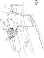
La
figure 9 est une représentation schématique écorchée d'une cuve de navire méthanier comportant un terminal de chargement/déchargement de cette cuve.Thefigure 9 is a cutaway schematic representation of a vessel tank LNG tank with a loading / unloading terminal of this tank.
En référence à la
En référence aux
La
Par exemple, les piliers 2 ont une section de 30x30mm, les renforts latéraux 4 et 6 ont une section de 30x21mm et le panneau de couvercle 7 a une épaisseur de 21mm.For example, the
Le bloc isolant 20 peut être fabriqué de plusieurs façons. Selon un mode de réalisation, le bloc isolant 20 est fabriqué en mettant en place une pluralité de structures d'entretoises 1 parallèlement les unes aux autres dans la cavité d'un moule parallélépipédique, les plateaux supérieurs 3 des structures d'entretoises 1 étant posés sur une paroi de fond du moule. Un panneau de fond 8 est fixé sur les plateaux inférieurs 5 des structures d'entretoise 1 et la garniture calorifuge 11 est injectée dans l'espace entre le panneau de fond 8 et la paroi de fond du moule de manière à noyer les piliers 2 des structures d'entretoise 1. L'injection peut être effectuée soit par les cotés ou le fond du moule, soit au travers de trous 14 aménagés dans le panneau de fond 8. Le bloc est ensuite retourné et un panneau de couvercle 7 est fixé sur les plateaux supérieurs 3 des structures d'entretoise 1. Finalement, le bloc isolant 20 est sorti de la cavité du moule.The insulating
Un autre mode de réalisation consiste à effectuer les mêmes étapes décrites ci-dessus mais en posant les plateaux inférieurs 5 contre le fond du moule, en fixant le panneau de couvercle 7 sur les plateaux supérieurs 3, et en injectant la mousse polymère 11 au travers de trous 14 ménagés dans le panneau de couvercle 7.Another embodiment consists in carrying out the same steps described above but by placing the lower plates 5 against the bottom of the mold, by fixing the
En référence à la
En référence aux
Dans le mode de réalisation de la
Dans le mode de réalisation de la
Dans le mode de réalisation de la
Les blocs isolant décrits ci-dessus peuvent être utilisée dans différents types de réservoirs, par exemple pour constituer une barrière isolante d'un réservoir de GNL dans une installation terrestre ou dans un ouvrage flottant comme un navire méthanier ou autre.The insulating blocks described above can be used in different types of tanks, for example to form an insulating barrier of an LNG tank in a land installation or in a floating structure such as a LNG tank or other.
En référence à la
De manière connue en soi, des canalisations de chargement/déchargement 73 disposées sur le pont supérieur du navire peuvent être raccordées, au moyen de connecteurs appropriées, à un terminal maritime ou portuaire pour transférer une cargaison de GNL depuis ou vers la cuve 71.In a manner known per se, loading /
La
Pour engendrer la pression nécessaire au transfert du gaz liquéfié, on met en oeuvre des pompes embarquées dans le navire 70 et/ou des pompes équipant l'installation à terre 77 et/ou des pompes équipant le poste de chargement et de déchargement 75.In order to generate the pressure necessary for the transfer of the liquefied gas, pumps on board the
Bien que l'invention ait été décrite en liaison avec plusieurs modes de réalisation particuliers, il est bien évident qu'elle n'y est nullement limitée et qu'elle comprend tous les équivalents techniques des moyens décrits ainsi que leurs combinaisons si celles-ci entrent dans le cadre de l'invention, telle que définie par les revendications. L'usage du verbe « comporter », « comprendre » ou « inclure » et de ses formes conjuguées n'exclut pas la présence d'autres éléments ou d'autres étapes que ceux énoncés dans une revendication. L'usage de l'article indéfini « un » ou « une » pour un élément ou une étape n'exclut pas, sauf mention contraire, la présence d'une pluralité de tels éléments ou étapes.Although the invention has been described in connection with several particular embodiments, it is obvious that it is not limited thereto and that it comprises all the technical equivalents of the means described and their combinations if they are within the scope of the invention as defined by the claims. The use of the verb "to include", "to understand" or "to include" and its conjugated forms does not exclude the presence of other elements or steps other than those set out in a claim. The use of the indefinite article "a" or "an" for an element or a step does not exclude, unless otherwise stated, the presence of a plurality of such elements or steps.
Dans les revendications, tout signe de référence entre parenthèses ne saurait être interprété comme une limitation de la revendication.In the claims, any reference sign in parentheses can not be interpreted as a limitation of the claim.
Claims (12)
- Insulating block (20) for manufacturing a wall of a fluid-tight and insulating tank, the insulating block (20) having a bottom panel (8), a cover panel (7) and a plurality of elongate spacer structures (1) located between the cover panel (7) and the bottom panel (8), the bottom panel and the cover panel being planar and parallel,
wherein the spacer structure (1) has in each case a lower plate (5), an upper plate (3) and a row of pillars (2) that are disposed between the lower plate and the upper plate and are fixed to the lower plate and the upper plate, the lower plate and the upper plate being kept spaced apart and parallel to one another by the row of pillars,
the insulating block comprising a thermally insulating liner (11) disposed between the bottom panel (8) and the cover panel (7) so as to fill the spaces between the pillars (2) of a spacer structure (1) and the spaces between the respective spacer structures (1), and characterized in that the spacer structures are disposed parallel to one another with the lower plate fixed to the bottom panel parallel to the bottom panel and the upper plate fixed to the cover panel parallel to the cover panel. - Insulating block according to Claim 1, characterized in that a spacer structure has an upper lateral reinforcement (4) positioned along the row of pillars (2), the upper lateral reinforcement being connected both to the set of pillars in the row and to the upper plate (3).
- Insulating block according to Claim 1 or 2, characterized in that a spacer structure (1) has a lower lateral reinforcement (6) positioned along the row of pillars (2), the lower lateral reinforcement being connected both to the set of pillars in the row and to the lower plate (5).
- Insulating block according to Claim 2 or 3, characterized in that a spacer structure has a pair of upper lateral reinforcements (4) and/or a pair of lower lateral reinforcements (6) which are positioned on either side of the row of pillars.
- Insulating block according to one of Claims 2 to 4, characterized in that the lateral reinforcement is a rod having a square or rectangular cross section.
- Insulating block according to one of the preceding claims, characterized in that the pillars (2) have a square or rectangular cross section.
- Insulating block according to one of the preceding claims, characterized in that the spacer structure (1) is produced from wood.
- Method for manufacturing an insulating block according to one of Claims 1 to 7, comprising the steps of:positioning a plurality of spacer structures (1) parallel to one another in the cavity of a mould, the upper plates (3) of the spacer structures being placed on a bottom wall of the mould,fixing a bottom panel (8) to the lower plates (5) of the spacer structures parallel to the lower plates,introducing a thermally insulating liner (11) into the space between the bottom panel (8) and the bottom wall of the mould so as to embed the pillars of the spacer structures in the insulating liner,turning over the block thus obtained,fixing a cover panel (7) to the upper plates of the spacer structures parallel to the upper plates, and removing the insulating block from the cavity of the mould.
- Fluid-tight and insulating tank having a tank wall held on a load-bearing structure, the tank wall including, in the direction of the thickness from the outside to the inside of the tank, a secondary insulating barrier held on the load-bearing structure, a secondary fluid-tight membrane (15) held on the secondary insulating barrier, a primary insulating barrier held on the secondary fluid-tight membrane and a primary fluid-tight membrane (16) held on the primary insulating barrier, characterized in that the primary insulating barrier and/or the secondary insulating barrier consist(s) essentially of a plurality of insulating blocks (20) according to one of Claims 1 to 7, which are juxtaposed in a repeating pattern.
- Ship (70) for transporting a cold liquid product, the ship having a double hull (72) and a tank (71) according to claim 9 disposed in the double hull.
- Use of a ship (70) according to Claim 10, in which a cold liquid product is carried through insulated pipelines (73, 79, 76, 81) from or to a floating or on-shore storage facility (77) to or from the tank (71) of the ship in order to load or offload from the ship.
- System for transferring a cold liquid product, the system comprising a ship (70) according to Claim 10, insulated pipelines (73, 79, 76, 81) arranged so as to connect the tank (71) installed in the hull of the ship to a floating or on-shore storage facility (77), and a pump for driving a flow of cold liquid product through the insulated pipelines from or to the floating or on-shore storage facility to or from the tank of the ship.
Applications Claiming Priority (2)
| Application Number | Priority Date | Filing Date | Title |
|---|---|---|---|
| FR1157036A FR2978749B1 (en) | 2011-08-01 | 2011-08-01 | INSULATING BLOCK FOR THE MANUFACTURE OF A TANK WALL |
| PCT/FR2012/051725 WO2013017773A2 (en) | 2011-08-01 | 2012-07-20 | Insulating block for manufacturing a tank wall |
Publications (2)
| Publication Number | Publication Date |
|---|---|
| EP2739896A2 EP2739896A2 (en) | 2014-06-11 |
| EP2739896B1 true EP2739896B1 (en) | 2018-08-08 |
Family
ID=46724497
Family Applications (1)
| Application Number | Title | Priority Date | Filing Date |
|---|---|---|---|
| EP12750432.2A Not-in-force EP2739896B1 (en) | 2011-08-01 | 2012-07-20 | Insulating block for manufacturing a tank wall |
Country Status (6)
| Country | Link |
|---|---|
| EP (1) | EP2739896B1 (en) |
| JP (1) | JP6134712B2 (en) |
| KR (1) | KR102092210B1 (en) |
| CN (1) | CN103857954B (en) |
| FR (1) | FR2978749B1 (en) |
| WO (1) | WO2013017773A2 (en) |
Families Citing this family (11)
| Publication number | Priority date | Publication date | Assignee | Title |
|---|---|---|---|---|
| KR101919166B1 (en) * | 2013-04-05 | 2018-11-16 | 현대중공업 주식회사 | Cargo tank for extremely low temperature substance carrier |
| FR3004512B1 (en) * | 2013-04-15 | 2016-09-30 | Gaztransport Et Technigaz | SEALED AND THERMALLY INSULATED TANK |
| FR3017924B1 (en) * | 2014-02-21 | 2016-08-26 | Gaztransport Et Technigaz | METHOD AND SYSTEM FOR INERTING A WALL OF A STORAGE TANK OF A LIQUEFIED FUEL GAS |
| FR3026459B1 (en) * | 2014-09-26 | 2017-06-09 | Gaztransport Et Technigaz | SEALED AND INSULATING TANK WITH A BRIDGING ELEMENT BETWEEN THE PANELS OF THE SECONDARY INSULATING BARRIER |
| CN105711756B (en) * | 2014-12-03 | 2017-11-21 | 江南造船(集团)有限责任公司 | The installation method of the vertical bearing insulation of A type independent liquid cargo tank inside bottom surfaces |
| CN105711753B (en) * | 2014-12-03 | 2017-12-05 | 江南造船(集团)有限责任公司 | The installation method of A type independent liquid cargo tank top surfaces floatation stopping device insulation |
| FR3030014B1 (en) * | 2014-12-15 | 2017-10-13 | Gaztransport Et Technigaz | INSULATING BLOCK SUITABLE FOR MAKING AN INSULATING WALL IN A WATERPROOF TANK |
| FR3037843B1 (en) | 2015-06-24 | 2018-01-05 | Gaztransport Et Technigaz | METHOD AND DEVICE FOR CUTTING FIBROUS OR ALVEOLA INSULATING MATERIAL |
| FR3072758B1 (en) | 2017-10-20 | 2019-11-01 | Gaztransport Et Technigaz | SEALED AND THERMALLY INSULATING TANK WITH SEVERAL ZONES |
| WO2019077253A1 (en) | 2017-10-20 | 2019-04-25 | Gaztransport Et Technigaz | Sealed and thermally insulating tank with several areas |
| FR3107941B1 (en) | 2020-03-09 | 2022-03-11 | Gaztransport Et Technigaz | INSULATING MODULAR BLOCK FOR WATERTIGHT AND THERMALLY INSULATING TANK |
Family Cites Families (10)
| Publication number | Priority date | Publication date | Assignee | Title |
|---|---|---|---|---|
| FR2068995A5 (en) * | 1969-11-29 | 1971-09-03 | Bridgestone Liquefied Gas Co | |
| JPS4931075B1 (en) * | 1969-11-29 | 1974-08-19 | ||
| US3972166A (en) * | 1974-08-23 | 1976-08-03 | Ishikawajima-Harima Jukogyo Kabushiki Kaisha | Heat insulation structure for liquefied gas storage tank |
| DE2441392C3 (en) * | 1974-08-29 | 1978-09-28 | Ishikawajima-Harima Jukogyo K.K., Tokio | Liquid gas tanks, in particular for ships |
| JPS52109615A (en) * | 1976-03-11 | 1977-09-14 | Mitsubishi Heavy Ind Ltd | Manufacturing method for inside insulated storage tank |
| FR2781557B1 (en) * | 1998-07-24 | 2000-09-15 | Gaz Transport & Technigaz | IMPROVEMENT FOR A WATERPROOF AND THERMALLY INSULATING TANK WITH PREFABRICATED PANELS |
| FR2877638B1 (en) * | 2004-11-10 | 2007-01-19 | Gaz Transp Et Technigaz Soc Pa | THERMALLY INSULATED AND THERMALLY INSULATED TANK WITH COMPRESSION-RESISTANT CALORIFIC ELEMENTS |
| KR100644217B1 (en) * | 2006-04-20 | 2006-11-10 | 한국가스공사 | Lng storage tank having improved insulation structure and manufacturing method |
| FR2931535B1 (en) * | 2008-05-21 | 2010-08-20 | Gaztransp Et Technigaz | BONDING FIXING OF INSULATION BLOCKS FOR LIQUEFIED GAS STORAGE TANK USING CORRUGATED CORDS |
| KR101122556B1 (en) * | 2009-08-24 | 2012-03-16 | 삼성중공업 주식회사 | Insulation structure for a lng carrier tank |
-
2011
- 2011-08-01 FR FR1157036A patent/FR2978749B1/en active Active
-
2012
- 2012-07-20 JP JP2014523361A patent/JP6134712B2/en active Active
- 2012-07-20 KR KR1020147005205A patent/KR102092210B1/en active IP Right Grant
- 2012-07-20 EP EP12750432.2A patent/EP2739896B1/en not_active Not-in-force
- 2012-07-20 WO PCT/FR2012/051725 patent/WO2013017773A2/en active Search and Examination
- 2012-07-20 CN CN201280037598.0A patent/CN103857954B/en active Active
Non-Patent Citations (1)
| Title |
|---|
| None * |
Also Published As
| Publication number | Publication date |
|---|---|
| KR102092210B1 (en) | 2020-03-23 |
| JP6134712B2 (en) | 2017-05-24 |
| FR2978749B1 (en) | 2014-10-24 |
| FR2978749A1 (en) | 2013-02-08 |
| JP2014521556A (en) | 2014-08-28 |
| EP2739896A2 (en) | 2014-06-11 |
| CN103857954B (en) | 2016-05-04 |
| KR20140049579A (en) | 2014-04-25 |
| WO2013017773A2 (en) | 2013-02-07 |
| WO2013017773A3 (en) | 2013-08-08 |
| CN103857954A (en) | 2014-06-11 |
Similar Documents
| Publication | Publication Date | Title |
|---|---|---|
| EP2739896B1 (en) | Insulating block for manufacturing a tank wall | |
| EP3362732B1 (en) | Sealed and thermally insulating tank | |
| EP2739895B1 (en) | Sealed, thermally-insulating vessel | |
| EP2859267B1 (en) | Sealed and thermally insulating tank | |
| WO2016097578A2 (en) | Insulating unit suitable for making an insulating wall in a sealed tank | |
| WO2014096600A1 (en) | Sealed, thermally insulating vessel | |
| EP3114387B1 (en) | Sealed and insulating vessel comprising a deflection element allowing the flow of gas at a corner | |
| EP2880356B1 (en) | Sealed and thermally insulating tank wall comprising spaced-apart support elements | |
| EP3803187A2 (en) | Thermally-insulating sealed tank | |
| WO2017207938A1 (en) | Insulating block and thermally-insulating sealed tank built into a polyhedral load-bearing structure | |
| WO2021074435A1 (en) | Sealed and thermally insulating tank | |
| WO2012123656A1 (en) | Insulating block for producing a tight wall of a tank | |
| WO2017207904A1 (en) | Thermally-insulating sealed tank incorporated into a polyhedron-shaped load-bearing structure | |
| WO2020039134A1 (en) | Thermally insulating and leaktight tank wall | |
| WO2019239048A1 (en) | Thermally insulating sealed tank | |
| EP2986885B1 (en) | Tight and thermally insulating vessel | |
| EP3596383A1 (en) | Thermally insulating sealed tank comprising a reinforcing insulating plug | |
| WO2013182776A1 (en) | Lagging element for a fluidtight and thermally insulated tank comprising a reinforced lid panel | |
| FR3061260A1 (en) | SEALED AND THERMALLY INSULATING TANK FOR STORAGE OF A FLUID | |
| WO2019239053A1 (en) | Fluid-tight vessel provided with an undulating joint element | |
| FR3089597A1 (en) | Watertight and thermally insulating tank | |
| EP3948055B1 (en) | Storage facility for liquefied gas | |
| FR3094452A1 (en) | Storage facility for liquefied gas |
Legal Events
| Date | Code | Title | Description |
|---|---|---|---|
| PUAI | Public reference made under article 153(3) epc to a published international application that has entered the european phase |
Free format text: ORIGINAL CODE: 0009012 |
|
| 17P | Request for examination filed |
Effective date: 20140227 |
|
| AK | Designated contracting states |
Kind code of ref document: A2 Designated state(s): AL AT BE BG CH CY CZ DE DK EE ES FI FR GB GR HR HU IE IS IT LI LT LU LV MC MK MT NL NO PL PT RO RS SE SI SK SM TR |
|
| RAP1 | Party data changed (applicant data changed or rights of an application transferred) |
Owner name: GAZTRANSPORT ET TECHNIGAZ S.A. |
|
| DAX | Request for extension of the european patent (deleted) | ||
| 17Q | First examination report despatched |
Effective date: 20150205 |
|
| GRAP | Despatch of communication of intention to grant a patent |
Free format text: ORIGINAL CODE: EPIDOSNIGR1 |
|
| STAA | Information on the status of an ep patent application or granted ep patent |
Free format text: STATUS: GRANT OF PATENT IS INTENDED |
|
| INTG | Intention to grant announced |
Effective date: 20180410 |
|
| RAP1 | Party data changed (applicant data changed or rights of an application transferred) |
Owner name: GAZTRANSPORT ET TECHNIGAZ |
|
| GRAS | Grant fee paid |
Free format text: ORIGINAL CODE: EPIDOSNIGR3 |
|
| GRAA | (expected) grant |
Free format text: ORIGINAL CODE: 0009210 |
|
| STAA | Information on the status of an ep patent application or granted ep patent |
Free format text: STATUS: THE PATENT HAS BEEN GRANTED |
|
| AK | Designated contracting states |
Kind code of ref document: B1 Designated state(s): AL AT BE BG CH CY CZ DE DK EE ES FI FR GB GR HR HU IE IS IT LI LT LU LV MC MK MT NL NO PL PT RO RS SE SI SK SM TR |
|
| REG | Reference to a national code |
Ref country code: GB Ref legal event code: FG4D Free format text: NOT ENGLISH |
|
| REG | Reference to a national code |
Ref country code: CH Ref legal event code: EP Ref country code: AT Ref legal event code: REF Ref document number: 1027416 Country of ref document: AT Kind code of ref document: T Effective date: 20180815 |
|
| REG | Reference to a national code |
Ref country code: IE Ref legal event code: FG4D Free format text: LANGUAGE OF EP DOCUMENT: FRENCH |
|
| REG | Reference to a national code |
Ref country code: DE Ref legal event code: R096 Ref document number: 602012049485 Country of ref document: DE |
|
| REG | Reference to a national code |
Ref country code: NL Ref legal event code: MP Effective date: 20180808 |
|
| REG | Reference to a national code |
Ref country code: LT Ref legal event code: MG4D |
|
| REG | Reference to a national code |
Ref country code: AT Ref legal event code: MK05 Ref document number: 1027416 Country of ref document: AT Kind code of ref document: T Effective date: 20180808 |
|
| PG25 | Lapsed in a contracting state [announced via postgrant information from national office to epo] |
Ref country code: FI Free format text: LAPSE BECAUSE OF FAILURE TO SUBMIT A TRANSLATION OF THE DESCRIPTION OR TO PAY THE FEE WITHIN THE PRESCRIBED TIME-LIMIT Effective date: 20180808 Ref country code: SE Free format text: LAPSE BECAUSE OF FAILURE TO SUBMIT A TRANSLATION OF THE DESCRIPTION OR TO PAY THE FEE WITHIN THE PRESCRIBED TIME-LIMIT Effective date: 20180808 Ref country code: RS Free format text: LAPSE BECAUSE OF FAILURE TO SUBMIT A TRANSLATION OF THE DESCRIPTION OR TO PAY THE FEE WITHIN THE PRESCRIBED TIME-LIMIT Effective date: 20180808 Ref country code: NL Free format text: LAPSE BECAUSE OF FAILURE TO SUBMIT A TRANSLATION OF THE DESCRIPTION OR TO PAY THE FEE WITHIN THE PRESCRIBED TIME-LIMIT Effective date: 20180808 Ref country code: IS Free format text: LAPSE BECAUSE OF FAILURE TO SUBMIT A TRANSLATION OF THE DESCRIPTION OR TO PAY THE FEE WITHIN THE PRESCRIBED TIME-LIMIT Effective date: 20181208 Ref country code: PL Free format text: LAPSE BECAUSE OF FAILURE TO SUBMIT A TRANSLATION OF THE DESCRIPTION OR TO PAY THE FEE WITHIN THE PRESCRIBED TIME-LIMIT Effective date: 20180808 Ref country code: LT Free format text: LAPSE BECAUSE OF FAILURE TO SUBMIT A TRANSLATION OF THE DESCRIPTION OR TO PAY THE FEE WITHIN THE PRESCRIBED TIME-LIMIT Effective date: 20180808 Ref country code: GR Free format text: LAPSE BECAUSE OF FAILURE TO SUBMIT A TRANSLATION OF THE DESCRIPTION OR TO PAY THE FEE WITHIN THE PRESCRIBED TIME-LIMIT Effective date: 20181109 Ref country code: BG Free format text: LAPSE BECAUSE OF FAILURE TO SUBMIT A TRANSLATION OF THE DESCRIPTION OR TO PAY THE FEE WITHIN THE PRESCRIBED TIME-LIMIT Effective date: 20181108 Ref country code: NO Free format text: LAPSE BECAUSE OF FAILURE TO SUBMIT A TRANSLATION OF THE DESCRIPTION OR TO PAY THE FEE WITHIN THE PRESCRIBED TIME-LIMIT Effective date: 20181108 Ref country code: AT Free format text: LAPSE BECAUSE OF FAILURE TO SUBMIT A TRANSLATION OF THE DESCRIPTION OR TO PAY THE FEE WITHIN THE PRESCRIBED TIME-LIMIT Effective date: 20180808 |
|
| PG25 | Lapsed in a contracting state [announced via postgrant information from national office to epo] |
Ref country code: AL Free format text: LAPSE BECAUSE OF FAILURE TO SUBMIT A TRANSLATION OF THE DESCRIPTION OR TO PAY THE FEE WITHIN THE PRESCRIBED TIME-LIMIT Effective date: 20180808 Ref country code: HR Free format text: LAPSE BECAUSE OF FAILURE TO SUBMIT A TRANSLATION OF THE DESCRIPTION OR TO PAY THE FEE WITHIN THE PRESCRIBED TIME-LIMIT Effective date: 20180808 Ref country code: LV Free format text: LAPSE BECAUSE OF FAILURE TO SUBMIT A TRANSLATION OF THE DESCRIPTION OR TO PAY THE FEE WITHIN THE PRESCRIBED TIME-LIMIT Effective date: 20180808 |
|
| PG25 | Lapsed in a contracting state [announced via postgrant information from national office to epo] |
Ref country code: ES Free format text: LAPSE BECAUSE OF FAILURE TO SUBMIT A TRANSLATION OF THE DESCRIPTION OR TO PAY THE FEE WITHIN THE PRESCRIBED TIME-LIMIT Effective date: 20180808 Ref country code: EE Free format text: LAPSE BECAUSE OF FAILURE TO SUBMIT A TRANSLATION OF THE DESCRIPTION OR TO PAY THE FEE WITHIN THE PRESCRIBED TIME-LIMIT Effective date: 20180808 Ref country code: RO Free format text: LAPSE BECAUSE OF FAILURE TO SUBMIT A TRANSLATION OF THE DESCRIPTION OR TO PAY THE FEE WITHIN THE PRESCRIBED TIME-LIMIT Effective date: 20180808 Ref country code: IT Free format text: LAPSE BECAUSE OF FAILURE TO SUBMIT A TRANSLATION OF THE DESCRIPTION OR TO PAY THE FEE WITHIN THE PRESCRIBED TIME-LIMIT Effective date: 20180808 Ref country code: CZ Free format text: LAPSE BECAUSE OF FAILURE TO SUBMIT A TRANSLATION OF THE DESCRIPTION OR TO PAY THE FEE WITHIN THE PRESCRIBED TIME-LIMIT Effective date: 20180808 |
|
| REG | Reference to a national code |
Ref country code: DE Ref legal event code: R097 Ref document number: 602012049485 Country of ref document: DE |
|
| PG25 | Lapsed in a contracting state [announced via postgrant information from national office to epo] |
Ref country code: SM Free format text: LAPSE BECAUSE OF FAILURE TO SUBMIT A TRANSLATION OF THE DESCRIPTION OR TO PAY THE FEE WITHIN THE PRESCRIBED TIME-LIMIT Effective date: 20180808 Ref country code: DK Free format text: LAPSE BECAUSE OF FAILURE TO SUBMIT A TRANSLATION OF THE DESCRIPTION OR TO PAY THE FEE WITHIN THE PRESCRIBED TIME-LIMIT Effective date: 20180808 Ref country code: SK Free format text: LAPSE BECAUSE OF FAILURE TO SUBMIT A TRANSLATION OF THE DESCRIPTION OR TO PAY THE FEE WITHIN THE PRESCRIBED TIME-LIMIT Effective date: 20180808 |
|
| PLBE | No opposition filed within time limit |
Free format text: ORIGINAL CODE: 0009261 |
|
| STAA | Information on the status of an ep patent application or granted ep patent |
Free format text: STATUS: NO OPPOSITION FILED WITHIN TIME LIMIT |
|
| 26N | No opposition filed |
Effective date: 20190509 |
|
| PG25 | Lapsed in a contracting state [announced via postgrant information from national office to epo] |
Ref country code: SI Free format text: LAPSE BECAUSE OF FAILURE TO SUBMIT A TRANSLATION OF THE DESCRIPTION OR TO PAY THE FEE WITHIN THE PRESCRIBED TIME-LIMIT Effective date: 20180808 |
|
| REG | Reference to a national code |
Ref country code: DE Ref legal event code: R119 Ref document number: 602012049485 Country of ref document: DE |
|
| PG25 | Lapsed in a contracting state [announced via postgrant information from national office to epo] |
Ref country code: MC Free format text: LAPSE BECAUSE OF FAILURE TO SUBMIT A TRANSLATION OF THE DESCRIPTION OR TO PAY THE FEE WITHIN THE PRESCRIBED TIME-LIMIT Effective date: 20180808 |
|
| REG | Reference to a national code |
Ref country code: CH Ref legal event code: PL |
|
| GBPC | Gb: european patent ceased through non-payment of renewal fee |
Effective date: 20190720 |
|
| PG25 | Lapsed in a contracting state [announced via postgrant information from national office to epo] |
Ref country code: TR Free format text: LAPSE BECAUSE OF FAILURE TO SUBMIT A TRANSLATION OF THE DESCRIPTION OR TO PAY THE FEE WITHIN THE PRESCRIBED TIME-LIMIT Effective date: 20180808 |
|
| REG | Reference to a national code |
Ref country code: BE Ref legal event code: MM Effective date: 20190731 |
|
| PG25 | Lapsed in a contracting state [announced via postgrant information from national office to epo] |
Ref country code: GB Free format text: LAPSE BECAUSE OF NON-PAYMENT OF DUE FEES Effective date: 20190720 Ref country code: DE Free format text: LAPSE BECAUSE OF NON-PAYMENT OF DUE FEES Effective date: 20200201 |
|
| PG25 | Lapsed in a contracting state [announced via postgrant information from national office to epo] |
Ref country code: LU Free format text: LAPSE BECAUSE OF NON-PAYMENT OF DUE FEES Effective date: 20190720 Ref country code: BE Free format text: LAPSE BECAUSE OF NON-PAYMENT OF DUE FEES Effective date: 20190731 Ref country code: CH Free format text: LAPSE BECAUSE OF NON-PAYMENT OF DUE FEES Effective date: 20190731 Ref country code: LI Free format text: LAPSE BECAUSE OF NON-PAYMENT OF DUE FEES Effective date: 20190731 |
|
| PG25 | Lapsed in a contracting state [announced via postgrant information from national office to epo] |
Ref country code: PT Free format text: LAPSE BECAUSE OF FAILURE TO SUBMIT A TRANSLATION OF THE DESCRIPTION OR TO PAY THE FEE WITHIN THE PRESCRIBED TIME-LIMIT Effective date: 20181208 |
|
| PG25 | Lapsed in a contracting state [announced via postgrant information from national office to epo] |
Ref country code: IE Free format text: LAPSE BECAUSE OF NON-PAYMENT OF DUE FEES Effective date: 20190720 |
|
| PG25 | Lapsed in a contracting state [announced via postgrant information from national office to epo] |
Ref country code: CY Free format text: LAPSE BECAUSE OF FAILURE TO SUBMIT A TRANSLATION OF THE DESCRIPTION OR TO PAY THE FEE WITHIN THE PRESCRIBED TIME-LIMIT Effective date: 20180808 |
|
| PG25 | Lapsed in a contracting state [announced via postgrant information from national office to epo] |
Ref country code: MT Free format text: LAPSE BECAUSE OF FAILURE TO SUBMIT A TRANSLATION OF THE DESCRIPTION OR TO PAY THE FEE WITHIN THE PRESCRIBED TIME-LIMIT Effective date: 20180808 Ref country code: HU Free format text: LAPSE BECAUSE OF FAILURE TO SUBMIT A TRANSLATION OF THE DESCRIPTION OR TO PAY THE FEE WITHIN THE PRESCRIBED TIME-LIMIT; INVALID AB INITIO Effective date: 20120720 |
|
| PG25 | Lapsed in a contracting state [announced via postgrant information from national office to epo] |
Ref country code: MK Free format text: LAPSE BECAUSE OF FAILURE TO SUBMIT A TRANSLATION OF THE DESCRIPTION OR TO PAY THE FEE WITHIN THE PRESCRIBED TIME-LIMIT Effective date: 20180808 |
|
| PG25 | Lapsed in a contracting state [announced via postgrant information from national office to epo] |
Ref country code: FR Free format text: LAPSE BECAUSE OF NON-PAYMENT OF DUE FEES Effective date: 20190108 |