EP2738803B1 - Phase change heat sink for transient thermal management - Google Patents
Phase change heat sink for transient thermal management Download PDFInfo
- Publication number
- EP2738803B1 EP2738803B1 EP13194990.1A EP13194990A EP2738803B1 EP 2738803 B1 EP2738803 B1 EP 2738803B1 EP 13194990 A EP13194990 A EP 13194990A EP 2738803 B1 EP2738803 B1 EP 2738803B1
- Authority
- EP
- European Patent Office
- Prior art keywords
- heat
- heat sink
- thermal
- phase change
- clamshell
- Prior art date
- Legal status (The legal status is an assumption and is not a legal conclusion. Google has not performed a legal analysis and makes no representation as to the accuracy of the status listed.)
- Active
Links
- 230000001052 transient effect Effects 0.000 title description 14
- 230000008859 change Effects 0.000 title description 7
- 239000012782 phase change material Substances 0.000 claims description 23
- 239000000463 material Substances 0.000 claims description 16
- 239000012188 paraffin wax Substances 0.000 claims description 7
- QGZKDVFQNNGYKY-UHFFFAOYSA-N Ammonia Chemical compound N QGZKDVFQNNGYKY-UHFFFAOYSA-N 0.000 claims description 4
- 230000005855 radiation Effects 0.000 claims description 4
- 239000000654 additive Substances 0.000 claims description 2
- 230000000996 additive effect Effects 0.000 claims description 2
- 229910021529 ammonia Inorganic materials 0.000 claims description 2
- 238000001816 cooling Methods 0.000 description 13
- 239000012071 phase Substances 0.000 description 13
- 239000007788 liquid Substances 0.000 description 12
- 230000017525 heat dissipation Effects 0.000 description 10
- 239000007787 solid Substances 0.000 description 8
- 230000000712 assembly Effects 0.000 description 5
- 238000000429 assembly Methods 0.000 description 5
- 230000008901 benefit Effects 0.000 description 3
- 230000008878 coupling Effects 0.000 description 3
- 238000010168 coupling process Methods 0.000 description 3
- 238000005859 coupling reaction Methods 0.000 description 3
- 238000004519 manufacturing process Methods 0.000 description 3
- PXHVJJICTQNCMI-UHFFFAOYSA-N Nickel Chemical compound [Ni] PXHVJJICTQNCMI-UHFFFAOYSA-N 0.000 description 2
- 230000007613 environmental effect Effects 0.000 description 2
- 238000005338 heat storage Methods 0.000 description 2
- 238000012423 maintenance Methods 0.000 description 2
- 230000004044 response Effects 0.000 description 2
- UXVMQQNJUSDDNG-UHFFFAOYSA-L Calcium chloride Chemical compound [Cl-].[Cl-].[Ca+2] UXVMQQNJUSDDNG-UHFFFAOYSA-L 0.000 description 1
- RYGMFSIKBFXOCR-UHFFFAOYSA-N Copper Chemical compound [Cu] RYGMFSIKBFXOCR-UHFFFAOYSA-N 0.000 description 1
- 229910000831 Steel Inorganic materials 0.000 description 1
- 239000011358 absorbing material Substances 0.000 description 1
- 238000010521 absorption reaction Methods 0.000 description 1
- 239000000853 adhesive Substances 0.000 description 1
- 230000001070 adhesive effect Effects 0.000 description 1
- XAGFODPZIPBFFR-UHFFFAOYSA-N aluminium Chemical compound [Al] XAGFODPZIPBFFR-UHFFFAOYSA-N 0.000 description 1
- 229910052782 aluminium Inorganic materials 0.000 description 1
- 239000001110 calcium chloride Substances 0.000 description 1
- 229910001628 calcium chloride Inorganic materials 0.000 description 1
- 239000003990 capacitor Substances 0.000 description 1
- 239000006229 carbon black Substances 0.000 description 1
- 230000002860 competitive effect Effects 0.000 description 1
- 230000008602 contraction Effects 0.000 description 1
- 229910052802 copper Inorganic materials 0.000 description 1
- 239000010949 copper Substances 0.000 description 1
- SBYXRAKIOMOBFF-UHFFFAOYSA-N copper tungsten Chemical compound [Cu].[W] SBYXRAKIOMOBFF-UHFFFAOYSA-N 0.000 description 1
- 230000003247 decreasing effect Effects 0.000 description 1
- 229920001971 elastomer Polymers 0.000 description 1
- 239000000806 elastomer Substances 0.000 description 1
- -1 for example Substances 0.000 description 1
- 239000007789 gas Substances 0.000 description 1
- 239000007791 liquid phase Substances 0.000 description 1
- 238000002844 melting Methods 0.000 description 1
- 230000008018 melting Effects 0.000 description 1
- 238000000034 method Methods 0.000 description 1
- 229910052759 nickel Inorganic materials 0.000 description 1
- 230000037361 pathway Effects 0.000 description 1
- 230000002035 prolonged effect Effects 0.000 description 1
- 239000010959 steel Substances 0.000 description 1
- 239000000758 substrate Substances 0.000 description 1
- 238000003466 welding Methods 0.000 description 1
Images
Classifications
-
- F—MECHANICAL ENGINEERING; LIGHTING; HEATING; WEAPONS; BLASTING
- F28—HEAT EXCHANGE IN GENERAL
- F28D—HEAT-EXCHANGE APPARATUS, NOT PROVIDED FOR IN ANOTHER SUBCLASS, IN WHICH THE HEAT-EXCHANGE MEDIA DO NOT COME INTO DIRECT CONTACT
- F28D15/00—Heat-exchange apparatus with the intermediate heat-transfer medium in closed tubes passing into or through the conduit walls ; Heat-exchange apparatus employing intermediate heat-transfer medium or bodies
- F28D15/02—Heat-exchange apparatus with the intermediate heat-transfer medium in closed tubes passing into or through the conduit walls ; Heat-exchange apparatus employing intermediate heat-transfer medium or bodies in which the medium condenses and evaporates, e.g. heat pipes
-
- F—MECHANICAL ENGINEERING; LIGHTING; HEATING; WEAPONS; BLASTING
- F28—HEAT EXCHANGE IN GENERAL
- F28D—HEAT-EXCHANGE APPARATUS, NOT PROVIDED FOR IN ANOTHER SUBCLASS, IN WHICH THE HEAT-EXCHANGE MEDIA DO NOT COME INTO DIRECT CONTACT
- F28D15/00—Heat-exchange apparatus with the intermediate heat-transfer medium in closed tubes passing into or through the conduit walls ; Heat-exchange apparatus employing intermediate heat-transfer medium or bodies
-
- H—ELECTRICITY
- H01—ELECTRIC ELEMENTS
- H01L—SEMICONDUCTOR DEVICES NOT COVERED BY CLASS H10
- H01L23/00—Details of semiconductor or other solid state devices
- H01L23/34—Arrangements for cooling, heating, ventilating or temperature compensation ; Temperature sensing arrangements
- H01L23/42—Fillings or auxiliary members in containers or encapsulations selected or arranged to facilitate heating or cooling
- H01L23/427—Cooling by change of state, e.g. use of heat pipes
-
- H—ELECTRICITY
- H05—ELECTRIC TECHNIQUES NOT OTHERWISE PROVIDED FOR
- H05K—PRINTED CIRCUITS; CASINGS OR CONSTRUCTIONAL DETAILS OF ELECTRIC APPARATUS; MANUFACTURE OF ASSEMBLAGES OF ELECTRICAL COMPONENTS
- H05K1/00—Printed circuits
- H05K1/02—Details
- H05K1/0201—Thermal arrangements, e.g. for cooling, heating or preventing overheating
- H05K1/0203—Cooling of mounted components
- H05K1/021—Components thermally connected to metal substrates or heat-sinks by insert mounting
-
- H—ELECTRICITY
- H01—ELECTRIC ELEMENTS
- H01L—SEMICONDUCTOR DEVICES NOT COVERED BY CLASS H10
- H01L2924/00—Indexing scheme for arrangements or methods for connecting or disconnecting semiconductor or solid-state bodies as covered by H01L24/00
- H01L2924/0001—Technical content checked by a classifier
- H01L2924/0002—Not covered by any one of groups H01L24/00, H01L24/00 and H01L2224/00
Definitions
- Heat producing devices such as printed circuit boards, often contain heat producing components, such as processors or voltage regulators.
- a thermal plane may be provided in combination with the heat producing devices to form an assembly to aid in the removal of heat, typically by providing additional conductive pathways to disperse the heat.
- air cooling and liquid cooling systems are used in open environments where the heat may be dissipated to the surroundings.
- the heat producing components may operate under transient modes of increased heat production where high heat dissipations are expected over short durations. The transient mode may exceed the capacity of the cooling system, unless the cooling system is sized for the worst-case transient response, which results in over capacity for steady-state operation.
- JP 2004-152895 A relates to a cooling device and electronic apparatus including the same, with the cooling device disclosed (see figure 10 thereof) as having a sheet of heat transferring material in which one portion of the sheet is folded over a second portion of the sheet and arranged to contact the surfaces of a plurality of heat generating bodies located between the sheet portions, with heat absorbing materials located on the outward facing surfaces of the sheet portions.
- GB 2 271 468 A describes a multi-chip module including a mechanically floated substrate on which integrated circuit devices are mounted.
- a clamshell assembly for a printed circuit board (PCB) having at least one heat producing component comprising: an upper thermal plane; a lower thermal plane spaced from the upper thermal plane to partially define a PCB chamber for holding the PCB; and a heat sink with a phase change material mounted to one of the upper thermal plane and the lower thermal plane; wherein the upper thermal plane and the lower thermal plane are coupled by a hinge to provide a housing structure that contains the PCB.
- PCB printed circuit board
- a printed circuit board (PCB) assembly 10 is shown comprising a PCB, exemplified as a pulse laser control board (PLCB) 12 to operate a pulse laser apparatus (not shown), having heat producing components 14, shown as microprocessors, on the PLCB top surface 16.
- PLCB pulse laser control board
- Pulse lasers are known to operate at high power requirements, causing high heat production in the PCB components, for short periods of time (on the order of seconds).
- additional heat producing components 14, such as power regulators, resistors, inductors, capacitors, etc. may be provided on the PCB.
- the PCB assembly 10 further comprises thermal planes 24, 26 having a heat sink 20, and thermal pads 22, conductively coupling the heat producing component to at least one of the thermal planes 24, 26.
- the thermal planes are shown as an upper thermal plane 24 and a lower thermal plane 26, each at least partially encompassing the top and bottom surfaces 16, 18 of the PLCB 12, respectively, and configured to mount to the PLCB 12.
- the thermal planes 24, 26 are illustrated as aluminum, which is efficient at conducting and dissipating heat. Alternately, the thermal planes 24, 26 may comprise any material able to efficiently conduct or dissipate heat.
- the PCB assembly 10 further defines a fastening component that is provided to aid in the mounting of the upper thermal plane 24 and the lower thermal plane 26 to the PLCB 12.
- the fastening component comprises a fastener, shown as a screw 28, received through an opening 30 in the upper thermal plane 24, PLCB 12, and lower thermal plane 26.
- Any suitable fastening component may be used.
- other mechanical fasteners e.g. bolts, nails, pins, etc.
- the screw 28 may couple the upper and lower thermal planes 24, 26 directly to each other, wherein the PLCB 12 will be partially or entirely contained within the planes 24, 26.
- the thermal planes may further be fastened using a screw-on clamp at two opposing side ends 29, 31 of each upper and lower thermal planes 24, 26.
- the upper thermal plane 24 is clamped to the lower thermal plane 26 to obtain a low compressive force (e.g. 0.023 to 0.069 m-kg) on to the PLCB 12 components.
- these clamps provide for a clamshell mount of the upper and lower thermal planes 24, 26 about the PLCB 12.
- thermal pads 22 illustrated as conductive putty, provide for physical contact and reliable thermal conduction between the heat producing component 14 and the upper thermal plane 24, as shown.
- Alternate embodiments of thermal pads may include thermal paste, or adhesive-type materials with suitable conductive properties.
- the heat sink 20 is defined by an inner wall 32 and includes a conductive frame 34 defining a plurality of chambers 35 in which the phase change material 36 is received. As illustrated, the frame 34 is illustrated as a grid of interconnected walls, which happen to define a honeycomb cross section.
- the frame 34 enhances the conduction of heat into and away from the phase change material 36 within the heat sink 20.
- the inner wall 32 is exemplified as an elastomer material for retaining the phase change material 36, but may be any type of material suitable for heat conduction.
- the frame 34 shown operates to segregate the phase change material in separate chambers 35, while providing an interconnected heat conduction path from the upper thermal plane 24 to the inner geometric chambers 35 of the phase change material.
- Other materials for example, copper, steel, nickel, or copper tungsten, etc., may provide similar structural and heat conductive properties functionality of frame 34, and provide design flexibility to incorporate or address concerns such as electromagnetic interference (EMI) protection, weigh, or thermal expansion/contraction.
- EMI electromagnetic interference
- This aforementioned list of grid materials should not be considered exhaustive, but rather, examples of a wide range of materials suitable for particular applications.
- the phase change material 36 is exemplified as paraffin wax (CaCl 2 ⁇ 6H 2 O), a solid which changes phase to a liquid when sufficient heat is absorbed, and further changes phase from a liquid back to a solid when sufficient heat is released.
- a typical melting point of paraffin wax is between 46 and 68 degrees Celsius. After the phase change from solid to liquid, the paraffin wax is able to further absorb supplementary heat, beyond the heat causing the phase change to occur.
- the paraffin wax is configured to repeatedly change phase from a solid to a liquid, and back to a solid, reliably for multiple cycles.
- phase change materials for example ammonia
- ammonia a material changes phase from a starting phase to at least one different phase in response to the conductive transfer of heat.
- the starting phase and at least one different phase may be one of solid, liquid, and gas.
- the paraffin wax may also include an additive material, such as carbon black, to increase the radiation heat transfer emissivity.
- the heat producing component 14 on the PLCB 12 uses electrical power over short durations (on the order of seconds), creating a mode of high power consumption interspersed with modes of low power consumption, and as a result, the need for transient high heat dissipation during the high power consumption modes.
- the heat produced by the heat producing component 14 is transferred by conduction to the thermal pad 22, followed by the upper and lower thermal planes 24, 26.
- the heat is then transferred to the heat sink 20 by the inner wall 32, with the frame 34 conducting the heat to the phase change material 36, where the heat is absorbed.
- the phase change material 36 provides a physical material for heat storage during heat dissipation of the PCB during the transient duration.
- the PCB assembly 10 will then shed the heat stored in the phase change material by conduction from the phase change material back to the thermal plane, via the frame 34, to the surrounding environment over time through radiation.
- phase change material 36 will melt, changing phase from a solid to a liquid or a liquid to a gas. This change of phase allows the phase change material 36 to absorb additional heat during the high heat transient cycle for later dissipation. In such a scenario, the liquid phase change material 36, upon subsequent heat release occurring during the low heat portion of the operation cycle, will phase change back to a solid.
- a 0.127 m by 0.1778 m PCB assembly comprising a thermal plane, and a heat sink with a honeycomb structure having 0.0051 m thickness of paraffin wax
- said PCB assembly is able to maintain a constant temperature of a 10.7 Watt heat load for 30 minutes without the need for external cooling.
- Additional heat dissipation devices may be used in conjunction with the exemplified embodiment, such as air cooling fins or liquid cooling channels, to provide for increased heat relief.
- the entire PCB assembly 10 structure may be coated or painted with a black, high emissivity, low gloss material to ensure effective radiation heat transfer to the surrounding environment.
- the above-mentioned embodiment is an example of the heat sink 20 configured in indirect conductive contact with the heat producing component 14 (via the thermal pad 22 and thermal planes 24, 26).
- the heat sink 20 may be configured to be in direct conductive contact with at least one heat producing component wherein the heat sink 20 and heat producing component have a common platform for heat transfer.
- FIG. 3 illustrates an alternative PCB assembly 110 according to an illustrative embodiment not falling under the invention.
- the second embodiment is similar to the first embodiment; therefore, like parts will be identified with like numerals increased by 100, with it being understood that the description of the like parts of the first embodiment applies to the second embodiment, unless otherwise noted.
- a difference between the first embodiment and the second embodiment, as illustrated, is that the upper thermal plane 124 is configured to receive only a single heat producing component, placing the heat sink 120 in direct conductive contact with the heat producing component 114, instead of full PLCB 112 coverage and indirect conductive contact of the first embodiment.
- the second embodiment further lacks the thermal pad of the first embodiment.
- the upper thermal layer 124 and heat sink 120 are configured or formed with protrusions and ridges with precision tolerance to mate directly over the heat producing component 114.
- one embodiment of the invention contemplates the thermal planes 24, 26 having indirect or direct conductive contact with the full PLCB surfaces 16, 18 or only a portion of the PLCB surfaces 16, 18.
- the thermal planes 24, 26 may have indirect or direct conductive contact with the full heat producing components 14 surface, or only a portion of the heat producing component 14 surfaces.
- the thermal pad would not be needed.
- a thermal pad or similar material may be provided to ensure complete contact with the thermal plane and the heat producing component.
- the heat sink 20 is shown at least partially embedded within each of the thermal planes 24, 26, other configurations are contemplated.
- the heat sink 20 may be completely embedded within one or both of the thermal planes 24, 26.
- the heat sink 20 may reside on one or both of an upper or lower surface of one or both of the thermal planes 24, 26.
- the heat sink 20 may be integrally formed with at least one of the thermal planes 24, 26.
- the heat sink 20 may be mounted to at least one of the thermal planes 24, 26.
- FIG. 4 illustrates alternate assemblies of the PLCB 212, including placement of heat producing components 214, such as microprocessors on the PLCB bottom surface 218, or even integrated within the PLCB 212, are encompassed by the one embodiment of the invention.
- the heat sinks 220 are in indirect contact with each heat producing component 214, via a lower thermal plane 226.
- FIG. 5 illustrates a different type of assembly that requires heat dissipation.
- a pulse radar chassis assembly 340 is shown, comprising a heat producing component 314, a chassis 338, and heat sinks 320. While a pulse radar chassis assembly 340 is shown, any chassis having a heat producing component that requires heat dissipation, such as a high power microwave chassis, a radio transmitting chassis, etc., is envisioned. Although the pulse radar chassis assembly 340 is shown having heat sinks 320 in indirect contact with the heat producing component 314, alternate configurations, as described herein, are envisioned.
- any of the embodiments may be combined.
- the embodiments of FIGS. 1 and 4 may be combined to locate the heat producing components on both the upper and lower surface of the PCB.
- One or more of these heat producing elements may have an individual heat sink according to the embodiment of FIG. 3 , while the remaining heat producing elements are connected to the heat sink according to the embodiment of FIG. 1 .
- the heat sinks of embodiments of FIGS. 1 and 3 may be combined resulting in "stacked' heat sinks.
- the embodiments disclosed herein provide a PCB assembly having a heat sink with phase change material.
- One advantage that may be realized in the above embodiments is that the above described embodiments have superior weight and size advantages over the conventional type PCB assemblies having air cooling fins or liquid cooling components.
- With the proposed phase change material heat sink arrangement a high heat dissipation can be achieved during transient heat conditions without additional heat dissipation elements since the reliable heat absorption of the phase change material is inherent, providing heat storage with the physical material for later release during lower heat production conditions.
- phase change material provides exceptional heat dissipation properties during steady state operation or reduced environmental cooling conditions, such as changes to environmental temperature under high solar settings.
- one aspect of the invention lowers the required enthalpy of a liquid or air heat exchanger needed to cool electronics during transient thermal cycles since the enthalpy is not designed for transient loads, but rather steady loads.
- PCB assemblies When designing PCB assemblies, important factors to address are size, weight, and reliability.
- the above described PCB assemblies have a decreased number of parts and less electrical draw compared to a PCB assembly having air or liquid cooling, making the complete system inherently more reliable. This results in a lower weight, smaller sized, increased performance, and increased reliability system.
- the lower number of parts and reduced maintenance will lead to a lower product costs and lower operating costs. Reduced weight and size correlate to competitive advantages.
Landscapes
- Engineering & Computer Science (AREA)
- Physics & Mathematics (AREA)
- Microelectronics & Electronic Packaging (AREA)
- Mechanical Engineering (AREA)
- General Engineering & Computer Science (AREA)
- Thermal Sciences (AREA)
- General Physics & Mathematics (AREA)
- Condensed Matter Physics & Semiconductors (AREA)
- Computer Hardware Design (AREA)
- Power Engineering (AREA)
- Sustainable Development (AREA)
- Life Sciences & Earth Sciences (AREA)
- Cooling Or The Like Of Electrical Apparatus (AREA)
- Cooling Or The Like Of Semiconductors Or Solid State Devices (AREA)
Description
- Heat producing devices, such as printed circuit boards, often contain heat producing components, such as processors or voltage regulators. A thermal plane may be provided in combination with the heat producing devices to form an assembly to aid in the removal of heat, typically by providing additional conductive pathways to disperse the heat. Typically, air cooling and liquid cooling systems are used in open environments where the heat may be dissipated to the surroundings. In certain instances, the heat producing components may operate under transient modes of increased heat production where high heat dissipations are expected over short durations. The transient mode may exceed the capacity of the cooling system, unless the cooling system is sized for the worst-case transient response, which results in over capacity for steady-state operation.
-
JP 2004-152895 A -
GB 2 271 468 A - In one aspect as defined in the appended claims, there is provided a clamshell assembly for a printed circuit board (PCB) having at least one heat producing component, comprising: an upper thermal plane; a lower thermal plane spaced from the upper thermal plane to partially define a PCB chamber for holding the PCB; and a heat sink with a phase change material mounted to one of the upper thermal plane and the lower thermal plane; wherein the upper thermal plane and the lower thermal plane are coupled by a hinge to provide a housing structure that contains the PCB.
- In the drawings:
-
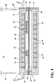
FIG. 1 is a schematic cross sectional view of a printed circuit board assembly where a heat producing component is in indirect conductive contact with the heat sink according to one embodiment of the invention. -
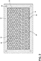
FIG. 2 is a schematic cross sectional view taken along line 2-2 ofFIG. 1 showing the heat sink. -
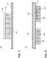
FIG. 3 is a schematic cross sectional view of a printed circuit board assembly where a heat producing component is in direct conductive contact with the heat sink according to a second embodiment of the invention. -
FIG. 4 is a schematic cross sectional view of a printed circuit board assembly showing an alternate heat producing component placement. -
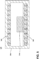
FIG. 5 is a schematic cross sectional of a chassis assembly where a heat producing component is in indirect conductive contact with the heat sink according to one embodiment of the invention. - The embodiments of the present invention are related to a heat dissipating assembly comprising at least one heat producing component. In the embodiment of
FIG. 1 , a printed circuit board (PCB)assembly 10 is shown comprising a PCB, exemplified as a pulse laser control board (PLCB) 12 to operate a pulse laser apparatus (not shown), havingheat producing components 14, shown as microprocessors, on the PLCBtop surface 16. Pulse lasers are known to operate at high power requirements, causing high heat production in the PCB components, for short periods of time (on the order of seconds). Although microprocessors are illustrated, additionalheat producing components 14, such as power regulators, resistors, inductors, capacitors, etc., may be provided on the PCB. - The
PCB assembly 10 further comprisesthermal planes heat sink 20, andthermal pads 22, conductively coupling the heat producing component to at least one of thethermal planes thermal plane 24 and a lowerthermal plane 26, each at least partially encompassing the top andbottom surfaces PLCB 12, respectively, and configured to mount to thePLCB 12. Thethermal planes thermal planes - The
PCB assembly 10 further defines a fastening component that is provided to aid in the mounting of the upperthermal plane 24 and the lowerthermal plane 26 to thePLCB 12. As illustrated, the fastening component comprises a fastener, shown as ascrew 28, received through anopening 30 in the upperthermal plane 24,PLCB 12, and lowerthermal plane 26. Any suitable fastening component may be used. For example, other mechanical fasteners, e.g. bolts, nails, pins, etc., may be used as well as non-mechanical fasteners, such as welding or adhesive. Alternatively, thescrew 28 may couple the upper and lowerthermal planes PLCB 12 will be partially or entirely contained within theplanes - The thermal planes may further be fastened using a screw-on clamp at two opposing side ends 29, 31 of each upper and lower
thermal planes thermal plane 24 is clamped to the lowerthermal plane 26 to obtain a low compressive force (e.g. 0.023 to 0.069 m-kg) on to thePLCB 12 components. - In a sense, these clamps provide for a clamshell mount of the upper and lower
thermal planes PLCB 12. The coupling of the upper and lowerthermal planes PLCB 12 in a manner similar to a clamshell. It is contemplated for the upper and lowerthermal planes PLCB 12. - The
thermal pads 22, illustrated as conductive putty, provide for physical contact and reliable thermal conduction between theheat producing component 14 and the upperthermal plane 24, as shown. Alternate embodiments of thermal pads may include thermal paste, or adhesive-type materials with suitable conductive properties. - Turning now to
FIG. 2 , the details of theheat sink 20 will be described. Theheat sink 20 is defined by aninner wall 32 and includes aconductive frame 34 defining a plurality of chambers 35 in which thephase change material 36 is received. As illustrated, theframe 34 is illustrated as a grid of interconnected walls, which happen to define a honeycomb cross section. - The
frame 34 enhances the conduction of heat into and away from thephase change material 36 within theheat sink 20. Theinner wall 32 is exemplified as an elastomer material for retaining thephase change material 36, but may be any type of material suitable for heat conduction. - The
frame 34 shown operates to segregate the phase change material in separate chambers 35, while providing an interconnected heat conduction path from the upperthermal plane 24 to the inner geometric chambers 35 of the phase change material. Other materials, for example, copper, steel, nickel, or copper tungsten, etc., may provide similar structural and heat conductive properties functionality offrame 34, and provide design flexibility to incorporate or address concerns such as electromagnetic interference (EMI) protection, weigh, or thermal expansion/contraction. This aforementioned list of grid materials should not be considered exhaustive, but rather, examples of a wide range of materials suitable for particular applications. - The
phase change material 36 is exemplified as paraffin wax (CaCl2 ∗6H2O), a solid which changes phase to a liquid when sufficient heat is absorbed, and further changes phase from a liquid back to a solid when sufficient heat is released. A typical melting point of paraffin wax is between 46 and 68 degrees Celsius. After the phase change from solid to liquid, the paraffin wax is able to further absorb supplementary heat, beyond the heat causing the phase change to occur. The paraffin wax is configured to repeatedly change phase from a solid to a liquid, and back to a solid, reliably for multiple cycles. - Other phase change materials, for example ammonia, are envisioned, so long as the material changes phase from a starting phase to at least one different phase in response to the conductive transfer of heat. The starting phase and at least one different phase may be one of solid, liquid, and gas. In the current embodiment, the paraffin wax may also include an additive material, such as carbon black, to increase the radiation heat transfer emissivity.
- During operation of the pulse laser, the
heat producing component 14 on thePLCB 12 uses electrical power over short durations (on the order of seconds), creating a mode of high power consumption interspersed with modes of low power consumption, and as a result, the need for transient high heat dissipation during the high power consumption modes. During these transient durations, the heat produced by theheat producing component 14 is transferred by conduction to thethermal pad 22, followed by the upper and lowerthermal planes heat sink 20 by theinner wall 32, with theframe 34 conducting the heat to thephase change material 36, where the heat is absorbed. In this sense, thephase change material 36 provides a physical material for heat storage during heat dissipation of the PCB during the transient duration. Upon the completion of the transient duration, thePCB assembly 10 will then shed the heat stored in the phase change material by conduction from the phase change material back to the thermal plane, via theframe 34, to the surrounding environment over time through radiation. - During exceptionally high heat or a prolonged transient heat condition, the
phase change material 36 will melt, changing phase from a solid to a liquid or a liquid to a gas. This change of phase allows thephase change material 36 to absorb additional heat during the high heat transient cycle for later dissipation. In such a scenario, the liquidphase change material 36, upon subsequent heat release occurring during the low heat portion of the operation cycle, will phase change back to a solid. - By way of non-limiting example, in a typical example of a low power, greater duration heat dissipation condition, a 0.127 m by 0.1778 m PCB assembly comprising a thermal plane, and a heat sink with a honeycomb structure having 0.0051 m thickness of paraffin wax, said PCB assembly is able to maintain a constant temperature of a 10.7 Watt heat load for 30 minutes without the need for external cooling.
- Additional heat dissipation devices may be used in conjunction with the exemplified embodiment, such as air cooling fins or liquid cooling channels, to provide for increased heat relief. Moreover, the
entire PCB assembly 10 structure may be coated or painted with a black, high emissivity, low gloss material to ensure effective radiation heat transfer to the surrounding environment. - The above-mentioned embodiment is an example of the
heat sink 20 configured in indirect conductive contact with the heat producing component 14 (via thethermal pad 22 andthermal planes 24, 26). Alternatively, it is envisioned that theheat sink 20 may be configured to be in direct conductive contact with at least one heat producing component wherein theheat sink 20 and heat producing component have a common platform for heat transfer. -
FIG. 3 illustrates analternative PCB assembly 110 according to an illustrative embodiment not falling under the invention. The second embodiment is similar to the first embodiment; therefore, like parts will be identified with like numerals increased by 100, with it being understood that the description of the like parts of the first embodiment applies to the second embodiment, unless otherwise noted. A difference between the first embodiment and the second embodiment, as illustrated, is that the upperthermal plane 124 is configured to receive only a single heat producing component, placing theheat sink 120 in direct conductive contact with theheat producing component 114, instead offull PLCB 112 coverage and indirect conductive contact of the first embodiment. As illustrated, the second embodiment further lacks the thermal pad of the first embodiment. - In this embodiment, the upper
thermal layer 124 andheat sink 120 are configured or formed with protrusions and ridges with precision tolerance to mate directly over theheat producing component 114. - Many other possible embodiments and configurations in addition to that shown in the above figures are contemplated by the present disclosure. For example, one embodiment of the invention contemplates the
thermal planes thermal planes heat producing components 14 surface, or only a portion of theheat producing component 14 surfaces. In direct contact configurations, the thermal pad would not be needed. Although a thermal pad or similar material may be provided to ensure complete contact with the thermal plane and the heat producing component. - While the
heat sink 20 is shown at least partially embedded within each of thethermal planes heat sink 20 may be completely embedded within one or both of thethermal planes heat sink 20 may reside on one or both of an upper or lower surface of one or both of thethermal planes heat sink 20 may be integrally formed with at least one of thethermal planes heat sink 20 may be mounted to at least one of thethermal planes - Additionally, the design and placement of the various components may be rearranged such that a number of different configurations could be realized. For example,
FIG. 4 illustrates alternate assemblies of thePLCB 212, including placement ofheat producing components 214, such as microprocessors on the PLCB bottom surface 218, or even integrated within thePLCB 212, are encompassed by the one embodiment of the invention. As shown, theheat sinks 220 are in indirect contact with eachheat producing component 214, via a lowerthermal plane 226. - Furthermore, non-PCB assemblies are included. For example,
FIG. 5 illustrates a different type of assembly that requires heat dissipation. InFIG. 5 , a pulseradar chassis assembly 340 is shown, comprising aheat producing component 314, achassis 338, and heat sinks 320. While a pulseradar chassis assembly 340 is shown, any chassis having a heat producing component that requires heat dissipation, such as a high power microwave chassis, a radio transmitting chassis, etc., is envisioned. Although the pulseradar chassis assembly 340 is shown havingheat sinks 320 in indirect contact with theheat producing component 314, alternate configurations, as described herein, are envisioned. - It is contemplated that any of the embodiments may be combined. For example, the embodiments of
FIGS. 1 and4 may be combined to locate the heat producing components on both the upper and lower surface of the PCB. One or more of these heat producing elements may have an individual heat sink according to the embodiment ofFIG. 3 , while the remaining heat producing elements are connected to the heat sink according to the embodiment ofFIG. 1 . It is further contemplated that the heat sinks of embodiments ofFIGS. 1 and3 may be combined resulting in "stacked' heat sinks. - The embodiments disclosed herein provide a PCB assembly having a heat sink with phase change material. One advantage that may be realized in the above embodiments is that the above described embodiments have superior weight and size advantages over the conventional type PCB assemblies having air cooling fins or liquid cooling components. With the proposed phase change material heat sink arrangement, a high heat dissipation can be achieved during transient heat conditions without additional heat dissipation elements since the reliable heat absorption of the phase change material is inherent, providing heat storage with the physical material for later release during lower heat production conditions.
- Moreover, higher PCB reliability can be achieved even when components do not have high heat transient conditions because the phase change material provides exceptional heat dissipation properties during steady state operation or reduced environmental cooling conditions, such as changes to environmental temperature under high solar settings. Additionally, one aspect of the invention lowers the required enthalpy of a liquid or air heat exchanger needed to cool electronics during transient thermal cycles since the enthalpy is not designed for transient loads, but rather steady loads.
- When designing PCB assemblies, important factors to address are size, weight, and reliability. The above described PCB assemblies have a decreased number of parts and less electrical draw compared to a PCB assembly having air or liquid cooling, making the complete system inherently more reliable. This results in a lower weight, smaller sized, increased performance, and increased reliability system. The lower number of parts and reduced maintenance will lead to a lower product costs and lower operating costs. Reduced weight and size correlate to competitive advantages.
- This written description uses examples to disclose the invention, including the best mode, and also to enable any person skilled in the art to practice the invention, including making and using any devices or systems and performing any incorporated methods. The patentable scope of the invention is defined by the claims.
Claims (8)
- A clamshell assembly (10) for a printed circuit board (PCB) (12) having at least one heat producing component (14), comprising:an upper thermal plane (24);a lower thermal plane (26) spaced from the upper thermal plane to partially define a PCB chamber for holding the PCB (12); anda heat sink (20) with a phase change material (36) mounted to one of the upper thermal plane (24) and the lower thermal plane (26); characterized in thatthe upper thermal plane (24) and the lower thermal plane (26) are coupled by a hinge to provide a housing structure that contains the PCB (12);the heat sink (20) further comprises a heat conducting frame (34) holding the phase change material (36); andthe heat conducting frame (34) is configured as a honeycomb.
- The clamshell circuit board assembly (10) of claim 1, wherein at least a portion of the phase change material (36) is aligned with the at least one heat producing component (14).
- The clamshell circuit board assembly (10) of either of claim 1 or 2, further comprising a thermal pad (22) in direct thermal contact with the at least one heat producing component (14) and at least one of the heat sink (20) and the one of the upper and lower thermal planes (24,26) to which the heat sink is mounted.
- The clamshell circuit board assembly (10) of claim 3, wherein the thermal pad (22) is in direct thermal contact with the one of the upper and lower thermal planes (24,26) to which the heat sink (20) is mounted.
- The clamshell circuit board assembly (10) of either of claim 3 or 4, wherein the thermal pad (22) and the heat sink (20) are on opposite sides of the one of the upper and lower thermal planes (24,26) to which the heat sink is mounted.
- The clamshell circuit board assembly (10) of any preceding claim, wherein the heat sink (20) comprises a first heat sink mounted to the upper thermal plane (24) and a second heat sink mounted to the lower thermal plane (26).
- The clamshell circuit board assembly (10) of any preceding claim, wherein the phase change material (36) is one of paraffin wax and ammonia.
- The clamshell circuit board assembly (10) of any preceding claim, wherein the phase change material (36) includes an additive material for high radiation heat transfer emissivity.
Applications Claiming Priority (1)
| Application Number | Priority Date | Filing Date | Title |
|---|---|---|---|
| US13/690,029 US9036352B2 (en) | 2012-11-30 | 2012-11-30 | Phase change heat sink for transient thermal management |
Publications (3)
| Publication Number | Publication Date |
|---|---|
| EP2738803A2 EP2738803A2 (en) | 2014-06-04 |
| EP2738803A3 EP2738803A3 (en) | 2017-12-27 |
| EP2738803B1 true EP2738803B1 (en) | 2020-03-11 |
Family
ID=49752969
Family Applications (1)
| Application Number | Title | Priority Date | Filing Date |
|---|---|---|---|
| EP13194990.1A Active EP2738803B1 (en) | 2012-11-30 | 2013-11-29 | Phase change heat sink for transient thermal management |
Country Status (6)
| Country | Link |
|---|---|
| US (1) | US9036352B2 (en) |
| EP (1) | EP2738803B1 (en) |
| JP (1) | JP2014110426A (en) |
| CN (1) | CN103857264B (en) |
| BR (1) | BR102013029452A2 (en) |
| CA (1) | CA2833896C (en) |
Cited By (1)
| Publication number | Priority date | Publication date | Assignee | Title |
|---|---|---|---|---|
| GB2558723B (en) * | 2016-10-31 | 2021-11-03 | Commissariat Energie Atomique | Protective shield for an electronic device |
Families Citing this family (20)
| Publication number | Priority date | Publication date | Assignee | Title |
|---|---|---|---|---|
| WO2013061409A1 (en) * | 2011-10-25 | 2013-05-02 | 富士通株式会社 | Water-cooling apparatus, electronic apparatus having water-cooling apparatus, and water-cooling method |
| CN103796486B (en) * | 2012-10-31 | 2017-02-08 | 英业达科技有限公司 | Electronic device |
| US11049794B2 (en) * | 2014-03-01 | 2021-06-29 | Advanced Micro Devices, Inc. | Circuit board with phase change material |
| US9836100B2 (en) * | 2014-10-15 | 2017-12-05 | Futurewei Technologies, Inc. | Support frame with integrated phase change material for thermal management |
| BR112017008332A2 (en) | 2014-11-12 | 2018-02-20 | Ge Aviation Systems Llc | heat sink sets |
| CN104868196A (en) * | 2015-06-02 | 2015-08-26 | 中投仙能科技(苏州)有限公司 | Lithium ion storage battery |
| US9713284B2 (en) | 2015-07-15 | 2017-07-18 | Hong Kong Applied Science And Technology Research Institute Co. Ltd. | Locally enhanced direct liquid cooling system for high power applications |
| TWI676405B (en) * | 2016-07-26 | 2019-11-01 | 日商Jx金屬股份有限公司 | Printed wiring boards, electronic equipment, ducts and metal materials |
| US10714425B2 (en) * | 2016-09-13 | 2020-07-14 | Apple Inc. | Flexible system integration to improve thermal properties |
| KR20180088193A (en) * | 2017-01-26 | 2018-08-03 | 삼성전자주식회사 | Apparatus and method of thermal management using adaptive thermal resistance and thermal capacity |
| US10415474B2 (en) * | 2017-01-31 | 2019-09-17 | General Electric Company | Method and system for phase change material component cooling |
| KR102271221B1 (en) * | 2017-03-14 | 2021-07-01 | 엘지이노텍 주식회사 | Thermo electric element |
| US10627167B2 (en) * | 2017-09-12 | 2020-04-21 | General Electric Company | Gas turbine engine having a heat absorption device utilizing phase change material |
| CN108413792A (en) * | 2018-03-12 | 2018-08-17 | 宁夏洪腾科技开发有限公司 | Heat pipe with switching function |
| CN108613421B (en) * | 2018-05-14 | 2019-08-30 | 上海理工大学 | It include the displacement air heat dump of modular microfluidic capsule phase change material |
| US20200109901A1 (en) * | 2018-10-03 | 2020-04-09 | Raytheon Company | Additively manufactured thermal energy storage units |
| US20200187386A1 (en) * | 2018-12-10 | 2020-06-11 | Zf Active Safety And Electronics Us Llc | Thermal interface assembly |
| CN113292863A (en) * | 2021-06-09 | 2021-08-24 | 中国人民解放军国防科技大学 | Transient composite material and preparation method and application thereof |
| US11674396B2 (en) | 2021-07-30 | 2023-06-13 | General Electric Company | Cooling air delivery assembly |
| CN114497813B (en) * | 2022-03-31 | 2022-06-28 | 深圳市森若新材科技有限公司 | Phase change composite film, and battery and chip assembly including the same |
Citations (1)
| Publication number | Priority date | Publication date | Assignee | Title |
|---|---|---|---|---|
| GB2271468A (en) * | 1992-10-06 | 1994-04-13 | Hewlett Packard Co | Mechanically floating multi-chip substrate |
Family Cites Families (37)
| Publication number | Priority date | Publication date | Assignee | Title |
|---|---|---|---|---|
| US4322737A (en) | 1979-11-20 | 1982-03-30 | Intel Corporation | Integrated circuit micropackaging |
| JPS60160151A (en) * | 1984-01-26 | 1985-08-21 | Fujitsu Ltd | Cooling system for integrated circuit |
| JPS62204341U (en) * | 1986-06-18 | 1987-12-26 | ||
| JPH01132199A (en) * | 1987-11-17 | 1989-05-24 | Fujitsu Ltd | Cooling structure for mounting of printed-circuit board |
| JPH05218250A (en) * | 1992-02-06 | 1993-08-27 | Mitsubishi Heavy Ind Ltd | Heat dissipating apparatus with variable heat transfer rate |
| US5477409A (en) | 1993-11-24 | 1995-12-19 | Vlsi Technology Inc. | Fusion heat sink for integrated circuit |
| AU697409B2 (en) * | 1995-01-25 | 1998-10-08 | Nortel Networks Corporation | Printed circuit board and heat sink arrangement |
| US5597035A (en) | 1995-08-18 | 1997-01-28 | Dell Usa, L.P. | For use with a heatsink a shroud having a varying cross-sectional area |
| JPH11274382A (en) * | 1998-01-21 | 1999-10-08 | Ricoh Microelectronics Co Ltd | Heat sink, manufacture thereof, and electronic device comprising the same |
| US6239502B1 (en) | 1999-11-22 | 2001-05-29 | Bae Systems Controls | Phase change assisted heat sink |
| EP1162659A3 (en) * | 2000-06-08 | 2005-02-16 | MERCK PATENT GmbH | Use of PCM in heat sinks for electronic devices |
| CN1290955A (en) * | 2000-10-31 | 2001-04-11 | 上海交通大学 | Heat-storage travelling wave tube |
| US6822867B2 (en) * | 2001-06-29 | 2004-11-23 | Intel Corporation | Electronic assembly with solderable heat sink and methods of manufacture |
| TW537436U (en) * | 2002-05-31 | 2003-06-11 | Quanta Comp Inc | Three-phase variable heat conducting structure |
| AU2003298561A1 (en) | 2002-08-23 | 2004-05-13 | Jonathan S. Dahm | Method and apparatus for using light emitting diodes |
| JP2004111665A (en) * | 2002-09-19 | 2004-04-08 | Hitachi Ltd | Electronic equipment |
| JP2004152895A (en) * | 2002-10-29 | 2004-05-27 | Sony Corp | Cooling device and electronic apparatus including the same |
| JP2004198036A (en) * | 2002-12-19 | 2004-07-15 | Fuji Electric Fa Components & Systems Co Ltd | Cooling device |
| KR100468783B1 (en) | 2003-02-11 | 2005-01-29 | 삼성전자주식회사 | Clothespin typed apparatus for dissipating heat generated from semiconductor module |
| JP3979531B2 (en) * | 2003-04-15 | 2007-09-19 | 日本ブロアー株式会社 | Electronic cooling device |
| JP2005012127A (en) * | 2003-06-20 | 2005-01-13 | Denso Corp | Electronic control apparatus |
| CN100426493C (en) * | 2004-12-04 | 2008-10-15 | 鸿富锦精密工业(深圳)有限公司 | Boiling cavity type radiator |
| CN100543103C (en) * | 2005-03-19 | 2009-09-23 | 清华大学 | Heat interfacial material and preparation method thereof |
| US7623360B2 (en) * | 2006-03-09 | 2009-11-24 | Laird Technologies, Inc. | EMI shielding and thermal management assemblies including frames and covers with multi-position latching |
| US20080123297A1 (en) | 2006-05-15 | 2008-05-29 | Isothermal Systems Research, Inc. | Hybrid clamshell blade system |
| JP4799296B2 (en) * | 2006-06-30 | 2011-10-26 | 株式会社東芝 | Electronics |
| JP4619387B2 (en) * | 2007-10-01 | 2011-01-26 | 株式会社日本自動車部品総合研究所 | Semiconductor device cooling device |
| CN101408301B (en) * | 2007-10-10 | 2012-09-19 | 富准精密工业(深圳)有限公司 | LED light fitting with heat radiating device |
| US20090184283A1 (en) * | 2008-01-18 | 2009-07-23 | Deborah Duen Ling Chung | Antioxidants for phase change ability and thermal stability enhancement |
| DE102008015782A1 (en) * | 2008-03-26 | 2009-10-01 | Rubitherm Technologies Gmbh | Method of making a phase change material composition |
| CN201214294Y (en) * | 2008-04-09 | 2009-04-01 | 孔庆山 | Composite board containing phase-change energy storage material |
| KR101446828B1 (en) | 2008-06-18 | 2014-10-30 | 브루사 일렉트로닉 아게 | Cooling system, in particular for electronic structural units |
| JP5381561B2 (en) | 2008-11-28 | 2014-01-08 | 富士電機株式会社 | Semiconductor cooling device |
| US7911796B2 (en) * | 2009-06-19 | 2011-03-22 | General Electric Company | Avionics chassis |
| CN101832001A (en) * | 2010-04-02 | 2010-09-15 | 建研建材有限公司 | Self-temperature-adjusting phase-change energy storage plate |
| CN201802003U (en) * | 2010-04-02 | 2011-04-20 | 建研建材有限公司 | Automatic temperature-regulating phase-change energy-storing plate |
| CN102173664A (en) * | 2011-01-17 | 2011-09-07 | 东南大学 | Graphite-paraffin composite phase-changing and energy-storing concrete and preparation method thereof |
-
2012
- 2012-11-30 US US13/690,029 patent/US9036352B2/en active Active
-
2013
- 2013-11-14 BR BR102013029452-7A patent/BR102013029452A2/en active Search and Examination
- 2013-11-21 CA CA2833896A patent/CA2833896C/en not_active Expired - Fee Related
- 2013-11-28 JP JP2013245536A patent/JP2014110426A/en active Pending
- 2013-11-29 EP EP13194990.1A patent/EP2738803B1/en active Active
- 2013-11-29 CN CN201310628340.4A patent/CN103857264B/en active Active
Patent Citations (1)
| Publication number | Priority date | Publication date | Assignee | Title |
|---|---|---|---|---|
| GB2271468A (en) * | 1992-10-06 | 1994-04-13 | Hewlett Packard Co | Mechanically floating multi-chip substrate |
Cited By (1)
| Publication number | Priority date | Publication date | Assignee | Title |
|---|---|---|---|---|
| GB2558723B (en) * | 2016-10-31 | 2021-11-03 | Commissariat Energie Atomique | Protective shield for an electronic device |
Also Published As
| Publication number | Publication date |
|---|---|
| CN103857264B (en) | 2017-09-15 |
| CA2833896C (en) | 2020-07-14 |
| JP2014110426A (en) | 2014-06-12 |
| US20140153193A1 (en) | 2014-06-05 |
| US9036352B2 (en) | 2015-05-19 |
| BR102013029452A2 (en) | 2014-11-18 |
| CA2833896A1 (en) | 2014-05-30 |
| EP2738803A3 (en) | 2017-12-27 |
| EP2738803A2 (en) | 2014-06-04 |
| CN103857264A (en) | 2014-06-11 |
Similar Documents
| Publication | Publication Date | Title |
|---|---|---|
| EP2738803B1 (en) | Phase change heat sink for transient thermal management | |
| US11864347B2 (en) | Heat sink assemblies for transient cooling | |
| US20120085520A1 (en) | Heat spreader with flexibly supported heat pipe | |
| EP2525632B1 (en) | Systems for circuit board heat transfer and method of assembling same | |
| JP5007296B2 (en) | Power module base | |
| CN100489921C (en) | Plasma display device | |
| US10736236B2 (en) | Power electronic conversion system | |
| US20150327402A1 (en) | Heat management for electronic enclosures | |
| US9942975B2 (en) | Scalable thermal solution for high frequency panel array applications or other applications | |
| JP6122616B2 (en) | Heat release device for printed circuit board for junction box | |
| WO2014140098A1 (en) | Heat spreader with flat pipe cooling element | |
| CN108207103A (en) | electronic chassis assembly | |
| US20120085527A1 (en) | Heat spreader with mechanically secured heat coupling element | |
| CN202918632U (en) | Double-sided cooling structure of multi-power components and electronic device thereof | |
| WO2017115627A1 (en) | Inverter | |
| EP3684154B1 (en) | Thermally conductive insert element for electronic unit | |
| US9474148B2 (en) | Stacked circuit board assembly with compliant middle member | |
| CN216413231U (en) | Heat radiation structure of phased array antenna, phased array antenna and satellite platform | |
| CN220492874U (en) | Inverter heat radiation structure and photovoltaic inverter | |
| JP5773976B2 (en) | refrigerator | |
| KR20110133346A (en) | Printed circuit board using graphite sheet | |
| CN114094303A (en) | Heat radiation structure of phased array antenna, phased array antenna and satellite platform |
Legal Events
| Date | Code | Title | Description |
|---|---|---|---|
| PUAI | Public reference made under article 153(3) epc to a published international application that has entered the european phase |
Free format text: ORIGINAL CODE: 0009012 |
|
| 17P | Request for examination filed |
Effective date: 20131129 |
|
| AK | Designated contracting states |
Kind code of ref document: A2 Designated state(s): AL AT BE BG CH CY CZ DE DK EE ES FI FR GB GR HR HU IE IS IT LI LT LU LV MC MK MT NL NO PL PT RO RS SE SI SK SM TR |
|
| AX | Request for extension of the european patent |
Extension state: BA ME |
|
| PUAL | Search report despatched |
Free format text: ORIGINAL CODE: 0009013 |
|
| AK | Designated contracting states |
Kind code of ref document: A3 Designated state(s): AL AT BE BG CH CY CZ DE DK EE ES FI FR GB GR HR HU IE IS IT LI LT LU LV MC MK MT NL NO PL PT RO RS SE SI SK SM TR |
|
| AX | Request for extension of the european patent |
Extension state: BA ME |
|
| RIC1 | Information provided on ipc code assigned before grant |
Ipc: H01L 23/427 20060101AFI20171117BHEP |
|
| STAA | Information on the status of an ep patent application or granted ep patent |
Free format text: STATUS: REQUEST FOR EXAMINATION WAS MADE |
|
| R17P | Request for examination filed (corrected) |
Effective date: 20180627 |
|
| RBV | Designated contracting states (corrected) |
Designated state(s): AL AT BE BG CH CY CZ DE DK EE ES FI FR GB GR HR HU IE IS IT LI LT LU LV MC MK MT NL NO PL PT RO RS SE SI SK SM TR |
|
| STAA | Information on the status of an ep patent application or granted ep patent |
Free format text: STATUS: EXAMINATION IS IN PROGRESS |
|
| 17Q | First examination report despatched |
Effective date: 20181019 |
|
| GRAP | Despatch of communication of intention to grant a patent |
Free format text: ORIGINAL CODE: EPIDOSNIGR1 |
|
| STAA | Information on the status of an ep patent application or granted ep patent |
Free format text: STATUS: GRANT OF PATENT IS INTENDED |
|
| INTG | Intention to grant announced |
Effective date: 20191001 |
|
| GRAS | Grant fee paid |
Free format text: ORIGINAL CODE: EPIDOSNIGR3 |
|
| GRAA | (expected) grant |
Free format text: ORIGINAL CODE: 0009210 |
|
| STAA | Information on the status of an ep patent application or granted ep patent |
Free format text: STATUS: THE PATENT HAS BEEN GRANTED |
|
| AK | Designated contracting states |
Kind code of ref document: B1 Designated state(s): AL AT BE BG CH CY CZ DE DK EE ES FI FR GB GR HR HU IE IS IT LI LT LU LV MC MK MT NL NO PL PT RO RS SE SI SK SM TR |
|
| REG | Reference to a national code |
Ref country code: GB Ref legal event code: FG4D |
|
| REG | Reference to a national code |
Ref country code: CH Ref legal event code: EP |
|
| REG | Reference to a national code |
Ref country code: AT Ref legal event code: REF Ref document number: 1244206 Country of ref document: AT Kind code of ref document: T Effective date: 20200315 |
|
| REG | Reference to a national code |
Ref country code: IE Ref legal event code: FG4D |
|
| REG | Reference to a national code |
Ref country code: DE Ref legal event code: R096 Ref document number: 602013066629 Country of ref document: DE |
|
| PG25 | Lapsed in a contracting state [announced via postgrant information from national office to epo] |
Ref country code: NO Free format text: LAPSE BECAUSE OF FAILURE TO SUBMIT A TRANSLATION OF THE DESCRIPTION OR TO PAY THE FEE WITHIN THE PRESCRIBED TIME-LIMIT Effective date: 20200611 Ref country code: RS Free format text: LAPSE BECAUSE OF FAILURE TO SUBMIT A TRANSLATION OF THE DESCRIPTION OR TO PAY THE FEE WITHIN THE PRESCRIBED TIME-LIMIT Effective date: 20200311 Ref country code: FI Free format text: LAPSE BECAUSE OF FAILURE TO SUBMIT A TRANSLATION OF THE DESCRIPTION OR TO PAY THE FEE WITHIN THE PRESCRIBED TIME-LIMIT Effective date: 20200311 |
|
| REG | Reference to a national code |
Ref country code: NL Ref legal event code: MP Effective date: 20200311 |
|
| PG25 | Lapsed in a contracting state [announced via postgrant information from national office to epo] |
Ref country code: BG Free format text: LAPSE BECAUSE OF FAILURE TO SUBMIT A TRANSLATION OF THE DESCRIPTION OR TO PAY THE FEE WITHIN THE PRESCRIBED TIME-LIMIT Effective date: 20200611 Ref country code: GR Free format text: LAPSE BECAUSE OF FAILURE TO SUBMIT A TRANSLATION OF THE DESCRIPTION OR TO PAY THE FEE WITHIN THE PRESCRIBED TIME-LIMIT Effective date: 20200612 Ref country code: SE Free format text: LAPSE BECAUSE OF FAILURE TO SUBMIT A TRANSLATION OF THE DESCRIPTION OR TO PAY THE FEE WITHIN THE PRESCRIBED TIME-LIMIT Effective date: 20200311 Ref country code: LV Free format text: LAPSE BECAUSE OF FAILURE TO SUBMIT A TRANSLATION OF THE DESCRIPTION OR TO PAY THE FEE WITHIN THE PRESCRIBED TIME-LIMIT Effective date: 20200311 Ref country code: HR Free format text: LAPSE BECAUSE OF FAILURE TO SUBMIT A TRANSLATION OF THE DESCRIPTION OR TO PAY THE FEE WITHIN THE PRESCRIBED TIME-LIMIT Effective date: 20200311 |
|
| REG | Reference to a national code |
Ref country code: LT Ref legal event code: MG4D |
|
| PG25 | Lapsed in a contracting state [announced via postgrant information from national office to epo] |
Ref country code: NL Free format text: LAPSE BECAUSE OF FAILURE TO SUBMIT A TRANSLATION OF THE DESCRIPTION OR TO PAY THE FEE WITHIN THE PRESCRIBED TIME-LIMIT Effective date: 20200311 |
|
| PG25 | Lapsed in a contracting state [announced via postgrant information from national office to epo] |
Ref country code: IS Free format text: LAPSE BECAUSE OF FAILURE TO SUBMIT A TRANSLATION OF THE DESCRIPTION OR TO PAY THE FEE WITHIN THE PRESCRIBED TIME-LIMIT Effective date: 20200711 Ref country code: PT Free format text: LAPSE BECAUSE OF FAILURE TO SUBMIT A TRANSLATION OF THE DESCRIPTION OR TO PAY THE FEE WITHIN THE PRESCRIBED TIME-LIMIT Effective date: 20200805 Ref country code: SK Free format text: LAPSE BECAUSE OF FAILURE TO SUBMIT A TRANSLATION OF THE DESCRIPTION OR TO PAY THE FEE WITHIN THE PRESCRIBED TIME-LIMIT Effective date: 20200311 Ref country code: LT Free format text: LAPSE BECAUSE OF FAILURE TO SUBMIT A TRANSLATION OF THE DESCRIPTION OR TO PAY THE FEE WITHIN THE PRESCRIBED TIME-LIMIT Effective date: 20200311 Ref country code: EE Free format text: LAPSE BECAUSE OF FAILURE TO SUBMIT A TRANSLATION OF THE DESCRIPTION OR TO PAY THE FEE WITHIN THE PRESCRIBED TIME-LIMIT Effective date: 20200311 Ref country code: CZ Free format text: LAPSE BECAUSE OF FAILURE TO SUBMIT A TRANSLATION OF THE DESCRIPTION OR TO PAY THE FEE WITHIN THE PRESCRIBED TIME-LIMIT Effective date: 20200311 Ref country code: SM Free format text: LAPSE BECAUSE OF FAILURE TO SUBMIT A TRANSLATION OF THE DESCRIPTION OR TO PAY THE FEE WITHIN THE PRESCRIBED TIME-LIMIT Effective date: 20200311 Ref country code: RO Free format text: LAPSE BECAUSE OF FAILURE TO SUBMIT A TRANSLATION OF THE DESCRIPTION OR TO PAY THE FEE WITHIN THE PRESCRIBED TIME-LIMIT Effective date: 20200311 |
|
| REG | Reference to a national code |
Ref country code: AT Ref legal event code: MK05 Ref document number: 1244206 Country of ref document: AT Kind code of ref document: T Effective date: 20200311 |
|
| REG | Reference to a national code |
Ref country code: DE Ref legal event code: R097 Ref document number: 602013066629 Country of ref document: DE |
|
| PLBE | No opposition filed within time limit |
Free format text: ORIGINAL CODE: 0009261 |
|
| STAA | Information on the status of an ep patent application or granted ep patent |
Free format text: STATUS: NO OPPOSITION FILED WITHIN TIME LIMIT |
|
| PG25 | Lapsed in a contracting state [announced via postgrant information from national office to epo] |
Ref country code: IT Free format text: LAPSE BECAUSE OF FAILURE TO SUBMIT A TRANSLATION OF THE DESCRIPTION OR TO PAY THE FEE WITHIN THE PRESCRIBED TIME-LIMIT Effective date: 20200311 Ref country code: ES Free format text: LAPSE BECAUSE OF FAILURE TO SUBMIT A TRANSLATION OF THE DESCRIPTION OR TO PAY THE FEE WITHIN THE PRESCRIBED TIME-LIMIT Effective date: 20200311 Ref country code: DK Free format text: LAPSE BECAUSE OF FAILURE TO SUBMIT A TRANSLATION OF THE DESCRIPTION OR TO PAY THE FEE WITHIN THE PRESCRIBED TIME-LIMIT Effective date: 20200311 Ref country code: AT Free format text: LAPSE BECAUSE OF FAILURE TO SUBMIT A TRANSLATION OF THE DESCRIPTION OR TO PAY THE FEE WITHIN THE PRESCRIBED TIME-LIMIT Effective date: 20200311 |
|
| 26N | No opposition filed |
Effective date: 20201214 |
|
| PG25 | Lapsed in a contracting state [announced via postgrant information from national office to epo] |
Ref country code: PL Free format text: LAPSE BECAUSE OF FAILURE TO SUBMIT A TRANSLATION OF THE DESCRIPTION OR TO PAY THE FEE WITHIN THE PRESCRIBED TIME-LIMIT Effective date: 20200311 Ref country code: SI Free format text: LAPSE BECAUSE OF FAILURE TO SUBMIT A TRANSLATION OF THE DESCRIPTION OR TO PAY THE FEE WITHIN THE PRESCRIBED TIME-LIMIT Effective date: 20200311 |
|
| PG25 | Lapsed in a contracting state [announced via postgrant information from national office to epo] |
Ref country code: MC Free format text: LAPSE BECAUSE OF FAILURE TO SUBMIT A TRANSLATION OF THE DESCRIPTION OR TO PAY THE FEE WITHIN THE PRESCRIBED TIME-LIMIT Effective date: 20200311 |
|
| REG | Reference to a national code |
Ref country code: CH Ref legal event code: PL |
|
| PG25 | Lapsed in a contracting state [announced via postgrant information from national office to epo] |
Ref country code: LU Free format text: LAPSE BECAUSE OF NON-PAYMENT OF DUE FEES Effective date: 20201129 |
|
| REG | Reference to a national code |
Ref country code: BE Ref legal event code: MM Effective date: 20201130 |
|
| PG25 | Lapsed in a contracting state [announced via postgrant information from national office to epo] |
Ref country code: CH Free format text: LAPSE BECAUSE OF NON-PAYMENT OF DUE FEES Effective date: 20201130 Ref country code: LI Free format text: LAPSE BECAUSE OF NON-PAYMENT OF DUE FEES Effective date: 20201130 |
|
| REG | Reference to a national code |
Ref country code: IE Ref legal event code: MM4A |
|
| PG25 | Lapsed in a contracting state [announced via postgrant information from national office to epo] |
Ref country code: IE Free format text: LAPSE BECAUSE OF NON-PAYMENT OF DUE FEES Effective date: 20201129 |
|
| PG25 | Lapsed in a contracting state [announced via postgrant information from national office to epo] |
Ref country code: TR Free format text: LAPSE BECAUSE OF FAILURE TO SUBMIT A TRANSLATION OF THE DESCRIPTION OR TO PAY THE FEE WITHIN THE PRESCRIBED TIME-LIMIT Effective date: 20200311 Ref country code: MT Free format text: LAPSE BECAUSE OF FAILURE TO SUBMIT A TRANSLATION OF THE DESCRIPTION OR TO PAY THE FEE WITHIN THE PRESCRIBED TIME-LIMIT Effective date: 20200311 Ref country code: CY Free format text: LAPSE BECAUSE OF FAILURE TO SUBMIT A TRANSLATION OF THE DESCRIPTION OR TO PAY THE FEE WITHIN THE PRESCRIBED TIME-LIMIT Effective date: 20200311 |
|
| PG25 | Lapsed in a contracting state [announced via postgrant information from national office to epo] |
Ref country code: MK Free format text: LAPSE BECAUSE OF FAILURE TO SUBMIT A TRANSLATION OF THE DESCRIPTION OR TO PAY THE FEE WITHIN THE PRESCRIBED TIME-LIMIT Effective date: 20200311 Ref country code: AL Free format text: LAPSE BECAUSE OF FAILURE TO SUBMIT A TRANSLATION OF THE DESCRIPTION OR TO PAY THE FEE WITHIN THE PRESCRIBED TIME-LIMIT Effective date: 20200311 |
|
| PG25 | Lapsed in a contracting state [announced via postgrant information from national office to epo] |
Ref country code: BE Free format text: LAPSE BECAUSE OF NON-PAYMENT OF DUE FEES Effective date: 20201130 |
|
| P01 | Opt-out of the competence of the unified patent court (upc) registered |
Effective date: 20230414 |
|
| PGFP | Annual fee paid to national office [announced via postgrant information from national office to epo] |
Ref country code: GB Payment date: 20231019 Year of fee payment: 11 |
|
| PGFP | Annual fee paid to national office [announced via postgrant information from national office to epo] |
Ref country code: FR Payment date: 20231019 Year of fee payment: 11 Ref country code: DE Payment date: 20231019 Year of fee payment: 11 |