EP2737213B1 - Getriebepumpe - Google Patents
Getriebepumpe Download PDFInfo
- Publication number
- EP2737213B1 EP2737213B1 EP12728484.2A EP12728484A EP2737213B1 EP 2737213 B1 EP2737213 B1 EP 2737213B1 EP 12728484 A EP12728484 A EP 12728484A EP 2737213 B1 EP2737213 B1 EP 2737213B1
- Authority
- EP
- European Patent Office
- Prior art keywords
- pump
- gearbox
- gearwheel
- gear
- housing
- Prior art date
- Legal status (The legal status is an assumption and is not a legal conclusion. Google has not performed a legal analysis and makes no representation as to the accuracy of the status listed.)
- Not-in-force
Links
- 229910001018 Cast iron Inorganic materials 0.000 claims description 11
- 229910052751 metal Inorganic materials 0.000 claims description 10
- 239000002184 metal Substances 0.000 claims description 10
- 230000005540 biological transmission Effects 0.000 description 6
- XEEYBQQBJWHFJM-UHFFFAOYSA-N Iron Chemical compound [Fe] XEEYBQQBJWHFJM-UHFFFAOYSA-N 0.000 description 4
- 238000005266 casting Methods 0.000 description 4
- 239000012208 gear oil Substances 0.000 description 4
- 238000002485 combustion reaction Methods 0.000 description 3
- FYYHWMGAXLPEAU-UHFFFAOYSA-N Magnesium Chemical compound [Mg] FYYHWMGAXLPEAU-UHFFFAOYSA-N 0.000 description 2
- 229910052782 aluminium Inorganic materials 0.000 description 2
- XAGFODPZIPBFFR-UHFFFAOYSA-N aluminium Chemical compound [Al] XAGFODPZIPBFFR-UHFFFAOYSA-N 0.000 description 2
- 238000009434 installation Methods 0.000 description 2
- 229910052742 iron Inorganic materials 0.000 description 2
- 229910052749 magnesium Inorganic materials 0.000 description 2
- 239000011777 magnesium Substances 0.000 description 2
- 239000003921 oil Substances 0.000 description 2
- 229910000831 Steel Inorganic materials 0.000 description 1
- 238000010276 construction Methods 0.000 description 1
- 230000001419 dependent effect Effects 0.000 description 1
- 238000006073 displacement reaction Methods 0.000 description 1
- 230000000694 effects Effects 0.000 description 1
- 239000000446 fuel Substances 0.000 description 1
- 238000005461 lubrication Methods 0.000 description 1
- 238000004519 manufacturing process Methods 0.000 description 1
- 230000010355 oscillation Effects 0.000 description 1
- 238000003825 pressing Methods 0.000 description 1
- 230000010349 pulsation Effects 0.000 description 1
- 238000005086 pumping Methods 0.000 description 1
- 238000005245 sintering Methods 0.000 description 1
- 230000006641 stabilisation Effects 0.000 description 1
- 238000011105 stabilization Methods 0.000 description 1
- 239000010959 steel Substances 0.000 description 1
- 238000003860 storage Methods 0.000 description 1
Images

Classifications
-
- F—MECHANICAL ENGINEERING; LIGHTING; HEATING; WEAPONS; BLASTING
- F04—POSITIVE - DISPLACEMENT MACHINES FOR LIQUIDS; PUMPS FOR LIQUIDS OR ELASTIC FLUIDS
- F04C—ROTARY-PISTON, OR OSCILLATING-PISTON, POSITIVE-DISPLACEMENT MACHINES FOR LIQUIDS; ROTARY-PISTON, OR OSCILLATING-PISTON, POSITIVE-DISPLACEMENT PUMPS
- F04C18/00—Rotary-piston pumps specially adapted for elastic fluids
- F04C18/08—Rotary-piston pumps specially adapted for elastic fluids of intermeshing-engagement type, i.e. with engagement of co-operating members similar to that of toothed gearing
- F04C18/12—Rotary-piston pumps specially adapted for elastic fluids of intermeshing-engagement type, i.e. with engagement of co-operating members similar to that of toothed gearing of other than internal-axis type
-
- F—MECHANICAL ENGINEERING; LIGHTING; HEATING; WEAPONS; BLASTING
- F04—POSITIVE - DISPLACEMENT MACHINES FOR LIQUIDS; PUMPS FOR LIQUIDS OR ELASTIC FLUIDS
- F04C—ROTARY-PISTON, OR OSCILLATING-PISTON, POSITIVE-DISPLACEMENT MACHINES FOR LIQUIDS; ROTARY-PISTON, OR OSCILLATING-PISTON, POSITIVE-DISPLACEMENT PUMPS
- F04C2/00—Rotary-piston machines or pumps
- F04C2/08—Rotary-piston machines or pumps of intermeshing-engagement type, i.e. with engagement of co-operating members similar to that of toothed gearing
- F04C2/10—Rotary-piston machines or pumps of intermeshing-engagement type, i.e. with engagement of co-operating members similar to that of toothed gearing of internal-axis type with the outer member having more teeth or tooth-equivalents, e.g. rollers, than the inner member
- F04C2/101—Rotary-piston machines or pumps of intermeshing-engagement type, i.e. with engagement of co-operating members similar to that of toothed gearing of internal-axis type with the outer member having more teeth or tooth-equivalents, e.g. rollers, than the inner member with a crescent-shaped filler element, located between the inner and outer intermeshing members
-
- F—MECHANICAL ENGINEERING; LIGHTING; HEATING; WEAPONS; BLASTING
- F04—POSITIVE - DISPLACEMENT MACHINES FOR LIQUIDS; PUMPS FOR LIQUIDS OR ELASTIC FLUIDS
- F04C—ROTARY-PISTON, OR OSCILLATING-PISTON, POSITIVE-DISPLACEMENT MACHINES FOR LIQUIDS; ROTARY-PISTON, OR OSCILLATING-PISTON, POSITIVE-DISPLACEMENT PUMPS
- F04C15/00—Component parts, details or accessories of machines, pumps or pumping installations, not provided for in groups F04C2/00 - F04C14/00
- F04C15/0057—Driving elements, brakes, couplings, transmission specially adapted for machines or pumps
- F04C15/0061—Means for transmitting movement from the prime mover to driven parts of the pump, e.g. clutches, couplings, transmissions
- F04C15/0073—Couplings between rotors and input or output shafts acting by interengaging or mating parts, i.e. positive coupling of rotor and shaft
-
- F—MECHANICAL ENGINEERING; LIGHTING; HEATING; WEAPONS; BLASTING
- F04—POSITIVE - DISPLACEMENT MACHINES FOR LIQUIDS; PUMPS FOR LIQUIDS OR ELASTIC FLUIDS
- F04C—ROTARY-PISTON, OR OSCILLATING-PISTON, POSITIVE-DISPLACEMENT MACHINES FOR LIQUIDS; ROTARY-PISTON, OR OSCILLATING-PISTON, POSITIVE-DISPLACEMENT PUMPS
- F04C2/00—Rotary-piston machines or pumps
- F04C2/30—Rotary-piston machines or pumps having the characteristics covered by two or more groups F04C2/02, F04C2/08, F04C2/22, F04C2/24 or having the characteristics covered by one of these groups together with some other type of movement between co-operating members
- F04C2/34—Rotary-piston machines or pumps having the characteristics covered by two or more groups F04C2/02, F04C2/08, F04C2/22, F04C2/24 or having the characteristics covered by one of these groups together with some other type of movement between co-operating members having the movement defined in groups F04C2/08 or F04C2/22 and relative reciprocation between the co-operating members
- F04C2/344—Rotary-piston machines or pumps having the characteristics covered by two or more groups F04C2/02, F04C2/08, F04C2/22, F04C2/24 or having the characteristics covered by one of these groups together with some other type of movement between co-operating members having the movement defined in groups F04C2/08 or F04C2/22 and relative reciprocation between the co-operating members with vanes reciprocating with respect to the inner member
Definitions
- the invention relates to a gear pump, in particular a gear oil pump of an automatic transmission of a motor vehicle according to the preamble of patent claim 1.
- Gear pumps in particular gear oil pumps are known from the prior art, which are driven by the internal combustion engine and / or an electric machine of the vehicle.
- pump systems are known which comprise two pumps, which are driven by the internal combustion engine or an electric machine.
- variable displacement pumps two or more pump concepts and pumps in combination with a pressure accumulator are known.
- a delivery unit for conveying fuel from a storage tank to the internal combustion engine of a motor vehicle with a feed pump which is designed as an internal gear pump and as an inner gear toothed ring and a gear meshing with this gear, wherein the pumping chambers formed between the teeth in the direction of the axis of rotation on the one hand are limited by a cover plate and on the other hand by a thrust washer and in the cover plate, a suction port and a pressure port of the feed pump are formed. Further, the gear is pressed by a pressing member against the thrust washer, whereby it is held in abutment against a base plate. This ensures that the ring gear and the gear can not perform any axial movements, which means that pressure pulsations of the pump and disturbing noises are avoided.
- the sliding on the base plate face of the thrust washer and the end face of the base plate are tuned to optimize the friction conditions.
- the teeth of the conveying members of the feed pump can be designed as helical gears, which results in an acting on the toothed ring axial force by which it is pressed against the thrust washer.
- the advantage should be achieved that between the thrust washer and the toothed ring a positive connection is required only in the direction of rotation.
- the publication DE 93 04 600 U1 describes a gear pump with a drive shaft whose surface is partially inclined.
- the gear is not fixed on this inclined surface, but on a flattening, which is located next to this.
- the present invention has for its object to provide a gear pump, in particular a gear oil pump of an automatic transmission of a motor vehicle, in which the pump gears are passed without increased manufacturing and assembly costs in the operation of the pump axially in the direction of the pump housing, whereby a sliding of the pump gears on the surface the pump cover or the ⁇ l Resultsflansches and thus increased wear of the pump cover and the ⁇ l Resultsflansches is avoided.
- a gear pump in particular a gear oil pump of an automatic transmission of a motor vehicle, proposed, comprising a pump housing and a pump cover or ⁇ l Economicssflansch, driven in the case of a gear pump, the driving pump gear and in the case of a vane pump, the diegelzellenrad via a pump connected to the drive shaft active pump driver is, wherein the Pumpenmitauerdon have such an inclined position, that in the case of a gear pump, the driving pump gear and in the case of a vane pump, the diegelzellenrad be directed axially towards the pump housing and come to the pump housing to a plant.
- the toothing between the driving and driven pump gears likewise has a specific inclination, such that the driven pump gear, e.g. in the case of an internal gear pump, the ring gear, is guided axially in the direction of the pump housing and comes to the pump housing to a plant.
- the pump housing is preferably designed as a cast iron housing and the pump cover or ⁇ l Operationsflansch preferably as a light metal component, for example of aluminum or magnesium casting.
- the concept according to the invention avoids the axial oscillation of the pump gears in the direction of the light metal component, which results in a significant reduction of the wear. Furthermore, when the pump is operating axially, a uniform air gap is created between the pump gears and the light metal component. Advantageously, thereby the efficiency of the pump can be increased.
- a transmission pump 1 which has a housing 2 made of cast iron and a pump cover 3 designed as a light metal component.
- the executed as an internal gear pump gear pump 1 is driven by a pump drive shaft 4, wherein for this purpose an operatively connected to the drive shaft 4 Pumpenmitcret 5 is provided, whereby the rotational movement of the drive shaft 4 is transmitted to the driving pump gear 6, which in turn as a ring gear, comprising a Internal gear running driven pump gear 7 drives.
- the gear pump 1 can be used for example as a transmission oil pump.
- FIG. 1 is the teeth between the driving and the driven pump gear provided with the reference numeral 8.
- the direction of rotation in the Operation of the gear pump 1 is in the in FIG. 2 shown top view illustrated by the arrow 9.
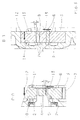
- FIG. 3 whose upper part is a sectional view taken along the line AA FIG. 2 and its lower part is a sectional view taken along the line BB FIG. 2 is, have the Pumpenmit loved ceremoni a targeted inclination, such that the driving pump gear 6 is selectively directed axially towards the cast iron housing 2 and comes to the cast iron housing 2 to a defined system, which is illustrated by the reference numeral 10.
- the toothing 8 between the driving pump gear 6 and the driven pump gear 7 also has a targeted inclination, such that the driven pump gear 7, is directed axially in the direction of the iron casting housing 2, whereby it at the cast iron housing 2 to a defined Appendix 14 comes as indicated by the lower part of the FIG. 3 illustrated.
- the helix angle of the toothing 8 between the driving pump gear 6 and the driven pump gear 7 is in the lower part of FIG. 3 shown and provided with the reference ⁇ .
- the axial force acting during operation of the gear pump 1 is illustrated by the arrow 12.
- the axial pendulum of the driving pump gear 6 and of the driven pump gear 7 in the direction of the pump cover 3 designed as a light metal component is avoided, which advantageously results in a significant reduction in wear and an increase in the service life of the gear pump 1.
Landscapes
- Engineering & Computer Science (AREA)
- Mechanical Engineering (AREA)
- General Engineering & Computer Science (AREA)
- Details And Applications Of Rotary Liquid Pumps (AREA)
- Rotary Pumps (AREA)
Description
- Die Erfindung bezieht sich auf eine Getriebepumpe, insbesondere auf eine Getriebeölpumpe eines Automatgetriebes eines Kraftfahrzeugs gemäß dem Oberbegriff des Patentanspruchs 1.
- Aus dem Stand der Technik sind Getriebepumpen, insbesondere Getriebeölpumpen bekannt, die über den Verbrennungsmotor und/oder eine elektrische Maschine des Fahrzeugs angetrieben werden. Des Weiteren sind Pumpensysteme bekannt, die zwei Pumpen umfassen, welche über den Verbrennungsmotor bzw. eine elektrische Maschine angetrieben werden. Ferner sind Verstellpumpen, zwei- oder mehrflutige Pumpenkonzepte sowie Pumpen in Kombination mit einem Druckspeicher bekannt.
- Als Zahnrad- und Flügelzellenpumpen ausgeführte Getriebepumpen sowie Kompressoren sind nach dem Stand der Technik axialkraftfrei aufgebaut, wodurch ein möglichst reibungsfreier Lauf der Pumpenzahnräder innerhalb der Pumpengehäuse erzielt werden soll.
- Ferner ist aus dem Stand der Technik bekannt, die Pumpengehäuse aus Eisenguss und die Pumpendeckel oder Ölführungsflansche als Leichtmetallbauteile aus Aluminium- oder Magnesiumguss herzustellen.
- Durch die axialkraftfreie Auslegung der Pumpenzahnräder entsteht in nachteiliger Weise eine Art Axialpendeln dieser Zahn- bzw. Flügelräder, wobei der Anteil der Pendelausschläge in Richtung des Pumpengehäuses und des Pumpendeckels bzw. Ölführungsflansches in etwa gleich sind.
- Das Axialpendeln der Pumpenzahnräder, die in der Regel aus Stahl oder durch Sintern hergestellt sind, in Richtung des Leichmetallbauteils, d.h. des Pumpendeckels bzw. des Ölführungsflansches führt zu einem höheren Verschleiß der Pumpeninnenfläche.
- Aus der
DE 43 15 432 A1 ist ein Förderaggregat zum Fördern von Kraftstoff aus einem Vorratstank zur Brennkraftmaschine eines Kraftfahrzeuges mit einer Förderpumpe bekannt, die als Innenzahnradpumpe ausgebildet ist und als Förderglieder einen innenverzahnten Zahnring und ein mit diesem kämmendes Zahnrad aufweist, wobei die zwischen den Verzahnungen gebildeten Pumpkammern in Richtung der Drehachse einerseits durch eine Deckplatte und andererseits durch eine Anlaufscheibe begrenzt sind und in der Deckplatte eine Saugöffnung und eine Drucköffnung der Förderpumpe ausgebildet sind. Ferner wird das Zahnrad durch ein Andrückelement gegen die Anlaufscheibe gedrückt, wodurch diese in der Anlage an einer Grundplatte gehalten wird. Dadurch wird erreicht, dass der Zahnring und das Zahnrad keine axialen Bewegungen ausführen können, was dazu führt, dass Druckpulsationen der Pumpe und störende Geräusche vermieden werden. - Beim bekannten Förderaggregat ist zudem vorgesehen, dass die auf der Grundplatte gleitende Stirnfläche der Anlaufscheibe und die Stirnfläche der Grundplatte zur Optimierung der Reibverhältnisse aufeinander abgestimmt sind. Die Verzahnungen der Förderglieder der Förderpumpe können als Schrägverzahnungen ausgeführt sein, wodurch sich eine auf den Zahnring wirkende axiale Kraft ergibt, durch die dieser gegen die Anlaufscheibe gedrückt wird. Dadurch soll der Vorteil erzielt werden, dass zwischen der Anlaufscheibe und dem Zahnring eine formschlüssige Verbindung lediglich in Drehrichtung erforderlich ist.
- Die aus der
DE 43 15 432 A1 bekannte Konstruktion weist den Nachteil auf, dass viele Bauteile, wie beispielsweise Andrückelemente und Anlaufscheiben benötigt werden, um eine axiale Stabilisierung zu erzielen. - Die Druckschrift
DE 93 04 600 U1 beschreibt eine Zahnradpumpe mit einer Antriebswelle deren Oberfläche teilweise schräggestellt ist. Das Zahnrad wird nicht auf dieser schräggestellter Oberfläche fixiert, sonder auf einer Abflachung, die sich neben dieser befindet. - Der vorliegenden Erfindung liegt die Aufgabe zugrunde, eine Getriebepumpe, insbesondere eine Getriebeölpumpe eines Automatgetriebes eines Kraftfahrzeugs anzugeben, bei der die Pumpenzahnräder ohne erhöhten Herstellungs- und Montageaufwand im Betrieb der Pumpe axial in Richtung des Pumpengehäuses geleitet werden, wodurch ein Gleiten der Pumpenzahnräder auf der Oberfläche des Pumpendeckels bzw. des Ölführungsflansches und somit ein erhöhter Verschleiß des Pumpendeckels bzw. des Ölführungsflansches vermieden wird.
- Diese Aufgabe wird durch die Merkmale des Patentanspruchs 1 gelöst. Weitere erfindungsgemäße Ausgestaltungen und Vorteile gehen aus den Unteransprüchen hervor.
- Demnach wird eine Getriebepumpe, insbesondere eine Getriebeölpumpe eines Automatgetriebes eines Kraftfahrzeugs, vorgeschlagen, umfassend ein Pumpengehäuse und einen Pumpendeckel oder Ölführungsflansch, bei der für den Fall einer Zahnradpumpe das antreibende Pumpenzahnrad und für den Fall einer Flügelzellenpumpe das Flügelzellenrad über einen mit der Pumpenantriebswelle wirkverbundenen Pumpenmitnehmer angetrieben wird, wobei die Pumpenmitnehmerflächen eine derartige Schrägstellung aufweisen, dass für den Fall einer Zahnradpumpe das antreibende Pumpenzahnrad und für den Fall einer Flügelzellenpumpe das Flügelzellenrad axial in Richtung des Pumpengehäuses geleitet werden und am Pumpengehäuse zu einer Anlage kommen.
- Im Rahmen einer Weiterbildung der Erfindung kann vorgesehen sein, dass für den Fall einer Zahnradpumpe die Verzahnung zwischen dem antreibenden und dem angetriebenen Pumpenzahnrad ebenfalls eine gezielte Schrägstellung aufweist, derart, dass auch das angetriebene Pumpenzahnrad, z.B. für den Fall einer Innenzahnradpumpe das Hohlrad, axial in Richtung des Pumpengehäuses geleitet wird und am Pumpengehäuse zu einer Anlage kommt.
- Gemäß der Erfindung ist das Pumpengehäuse vorzugsweise als Eisengussgehäuse und der Pumpendeckel oder Ölführungsflansch vorzugsweise als Leichtmetallbauteil, beispielsweise aus Aluminium- oder Magnesiumguss, ausgeführt.
- Durch die erfindungsgemäße Konzeption wird das Axialpendeln der Pumpenzahnräder in Richtung des Leichtmetallbauteils vermieden, was in einer signifikanten Reduzierung des Verschleißes resultiert. Des Weiteren entsteht im Betrieb der Pumpe axial betrachtet zwischen den Pumpenzahnrädern und dem Leichtmetallbauteil ein gleichmäßiger Luftspalt. In vorteilhafter Weise kann dadurch der Wirkungsgrad der Pumpe erhöht werden.
- Ein gezieltes, geringfügiges Gleiten der Pumpenzahnräder auf der Oberfläche des Eisengussgehäuses ist aufgrund des Eigenschmierungseffektes von Eisenguss unkritisch.
- Die Erfindung wird im Folgenden anhand der beigefügten Figuren beispielhaft näher erläutert. Es zeigen:
- Figur 1:
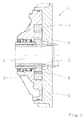
- Eine schematische Schnittansicht einer nach dem Stand der Technik ausgeführten Innenzahnradpumpe zur Veranschaulichung der für die Erfindung relevanten Bauteile;
- Figur 2:
- eine Draufsicht einer gemäß der Erfindung ausgeführten Innenzahnradpumpe; und
- Figur 3:
- eine Schnittansicht entlang der Linie A-A aus
Figur 2 und eine Schnittansicht entlang der Linie B-B ausFigur 2 . - Gleiche Bezugszeichen bezeichnen gleiche Bauteile.
- In
Figur 1 ist eine Getriebepumpe 1 dargestellt, welche ein aus Eisenguss hergestelltes Gehäuse 2 und einen als Leichtmetallbauteil ausgeführten Pumpendeckel 3 aufweist. Die als Innenzahnradpumpe ausgeführte Getriebepumpe 1 wird durch eine Pumpenantriebswelle 4 angetrieben, wobei zu diesem Zweck ein mit der Antriebswelle 4 wirkverbundener Pumpenmitnehmer 5 vorgesehen ist, wodurch die Drehbewegung der Antriebswelle 4 auf das antreibende Pumpenzahnrad 6 übertragen wird, welches wiederum das als Hohlrad, umfassend eine Innenverzahnung ausgeführte angetriebene Pumpenzahnrad 7 antreibt. Die Getriebepumpe 1 kann beispielsweise als Getriebeölpumpe verwendet werden. - In
Figur 1 ist die die Verzahnung zwischen dem antreibenden und dem angetriebenen Pumpenzahnrad mit dem Bezugszeichen 8 versehen. Die Rotationsrichtung im Betrieb der Getriebepumpe 1 ist in der inFigur 2 gezeigten Draufsicht durch den Pfeil 9 veranschaulicht. - Gemäß der Erfindung und bezugnehmend auf
Figur 3 , deren oberer Teil eine Schnittansicht entlang der Linie A-A ausFigur 2 und deren unterer Teil eine Schnittansicht entlang der Linie B-B ausFigur 2 ist, weisen die Pumpenmitnehmerflächen eine gezielte Schrägstellung auf, derart, dass das antreibende Pumpenzahnrad 6 gezielt axial in Richtung des Eisengussgehäuses 2 geleitet wird und an dem Eisengussgehäuse 2 zu einer definierten Anlage kommt, die durch das Bezugszeichen 10 veranschaulicht wird. - Die erzeugte Axialkraft entlang der Hauptachse der Getriebepumpe 1 wird in Figur 3 durch den Pfeil 12 veranschaulicht, wobei Pfeil 13 die Rotationsrichtung im Betrieb der Getriebepumpe 1 andeutet. Der resultierende Schrägungswinkel zwischen der Antriebswelle 4 und der Pumpenmitnehmerfläche des Pumpenmitnehmers 5 ist im oberen Teil der
Figur 3 gezeigt und mit dem Bezugszeichen α versehen. - Des Weiteren entsteht gemäß der Erfindung und bezugnehmend auf den oberen Teil der
Figur 3 axial betrachtet zwischen dem antreibenden Pumpenzahnrad 6 und dem als Leichtmetallbauteil ausgeführten Pumpendeckel 3 ein gleichmäßiger, stabiler Luftspalt 11. - Bei dem gezeigten Beispiel weist die Verzahnung 8 zwischen dem antreibenden Pumpenzahnrad 6 und dem angetriebenen Pumpenzahnrad 7 ebenfalls eine gezielte Schrägstellung auf, derart, dass auch das angetriebene Pumpenzahnrad 7, axial in Richtung des Eisengussgehäuses 2 geleitet wird, wodurch es an dem Eisengussgehäuse 2 zu einer definierten Anlage 14 kommt, wie anhand des unteren Teils der
Figur 3 veranschaulicht. Der Schrägungswinkel der Verzahnung 8 zwischen dem antreibenden Pumpenzahnrad 6 und dem angetriebenen Pumpenzahnrad 7 ist im unteren Teil derFigur 3 gezeigt und mit dem Bezugszeichen β versehen. Die im Betrieb der Getriebepumpe 1 wirkende Axialkraft ist durch den Pfeil 12 veranschaulicht. - Wie dem unteren Teil der
Figur 3 zu entnehmen, entsteht axial betrachtet auch zwischen dem angetriebenen Pumpenzahnrad 7 und dem als Leichtmetallbauteil ausgeführten Pumpendeckel 3 ein gleichmäßiger, stabiler Luftspalt 15. - Durch die Erfindung wird das Axialpendeln des antreibenden Pumpenzahnrades 6 und des angetriebenen Pumpenzahnrades 7 in Richtung des als Leichtmetallbauteil ausgeführten Pumpendeckels 3 vermieden, was in vorteilhafter Weise in einer signifikanten Reduzierung des Verschleißes und einer Erhöhung der Lebensdauer der Getriebepumpe 1 resultiert.
-
- 1
- Getriebepumpe
- 2
- aus Eisenguss hergestelltes Gehäuse
- 3
- als Leichtmetallbauteil ausgeführter Pumpendeckel
- 4
- Pumpenantriebswelle
- 5
- Pumpenmitnehmer
- 6
- antreibendes Pumpenzahnrad
- 7
- angetriebenes Pumpenzahnrad
- 8
- Verzahnung zwischen dem antreibenden Pumpenzahnrad 6 und dem angetriebenen Pumpenzahnrad 7
- 9
- Rotationsrichtung
- 10
- Anlage des antreibenden Pumpenzahnrades 6 an dem Eisengussgehäuse 2
- 11
- Luftspalt
- 12
- Axialkraft
- 13
- Rotationsrichtung
- 14
- Anlage des angetriebenen Pumpenzahnrades 7 an dem Eisengussgehäuse 2
- 15
- Luftspalt
- α
- Schrägungswinkel
- β
- Schrägungswinkel
Claims (7)
- Getriebepumpe (1), insbesondere eine Getriebeölpumpe eines Automatgetriebes eines Kraftfahrzeugs, welche als Zahnradpumpe oder als Flügelzellenpumpe ausgebildet ist, umfassend ein Pumpengehäuse (2) und einen Pumpendeckel (3) oder Ölführungsflansch, bei der für den Fall einer Zahnradpumpe das antreibende Pumpenzahnrad (6) und für den Fall einer Flügelzellenpumpe das Flügelzellenrad über einen mit der Pumpenantriebswelle (4) wirkverbundenen Pumpenmitnehmer (5) angetrieben wird, dadurch gekennzeichnet, dass die Pumpenmitnehmerflächen eine derartige Schrägstellung aufweisen, dass für den Fall einer Zahnradpumpe das antreibende Pumpenzahnrad (6) und für den Fall einer Flügelzellenpumpe das Flügelzellenrad axial in Richtung des Pumpengehäuses (2) geleitet wird und an dem Pumpengehäuse (2) zu einer Anlage kommt.
- Getriebepumpe (1) nach Anspruch 1, dadurch gekennzeichnet, dass für den Fall einer Zahnradpumpe die Verzahnung (8) zwischen dem antreibenden Pumpenzahnrad (6) und dem angetriebenen Pumpenzahnrad (7) eine derartige Schrägstellung aufweist, dass das angetriebene Pumpenzahnrad (7) axial in Richtung des Pumpengehäuses (2) geleitet wird, wodurch es an dem Pumpengehäuse (2) zu einer Anlage (14) kommt.
- Getriebepumpe (1) nach Anspruch 1 oder 2, dadurch gekennzeichnet, dass axial betrachtet zwischen dem antreibenden Pumpenzahnrad (6) und dem Pumpendeckel (3) ein gleichmäßiger, stabiler Luftspalt (11) entsteht.
- Getriebepumpe (1) nach Anspruch 2 oder 3, dadurch gekennzeichnet, dass axial betrachtet zwischen dem angetriebenen Pumpenzahnrad (7) und dem Pumpendeckel (3) ein gleichmäßiger, stabiler Luftspalt (15) entsteht.
- Getriebepumpe (1) nach einem der vorangehenden Ansprüche 1 bis 4, dadurch gekennzeichnet, dass das Pumpengehäuse (2) als Eisengussgehäuse ausgebildet ist.
- Getriebepumpe (1) nach einem der vorangehenden Ansprüche 1 bis 5, dadurch gekennzeichnet, dass der Pumpendeckel (3) als Leichtmetallbauteil ausgeführt ist.
- Getriebepumpe (1), nach einem der vorangehenden Ansprüche 1 bis 6, dadurch gekennzeichnet, dass sie als Getriebeölpumpe für ein Kraftfahrzeug verwendet wird.
Applications Claiming Priority (2)
| Application Number | Priority Date | Filing Date | Title |
|---|---|---|---|
| DE102011080048A DE102011080048A1 (de) | 2011-07-28 | 2011-07-28 | Getriebepumpe |
| PCT/EP2012/061330 WO2013013883A2 (de) | 2011-07-28 | 2012-06-14 | Getriebepumpe |
Publications (2)
| Publication Number | Publication Date |
|---|---|
| EP2737213A2 EP2737213A2 (de) | 2014-06-04 |
| EP2737213B1 true EP2737213B1 (de) | 2016-10-12 |
Family
ID=46320940
Family Applications (1)
| Application Number | Title | Priority Date | Filing Date |
|---|---|---|---|
| EP12728484.2A Not-in-force EP2737213B1 (de) | 2011-07-28 | 2012-06-14 | Getriebepumpe |
Country Status (5)
| Country | Link |
|---|---|
| US (1) | US20140161656A1 (de) |
| EP (1) | EP2737213B1 (de) |
| CN (1) | CN103717900A (de) |
| DE (1) | DE102011080048A1 (de) |
| WO (1) | WO2013013883A2 (de) |
Family Cites Families (9)
| Publication number | Priority date | Publication date | Assignee | Title |
|---|---|---|---|---|
| DE2314586A1 (de) * | 1973-03-23 | 1974-09-26 | Woodling George Victor | Druckmitteldruckbetaetigter mechanismus mit einem stator und einem rotor |
| DE2702963C2 (de) * | 1977-01-25 | 1983-12-01 | Manfred 8011 Kirchheim Schmid | Kombinierte Touren- und Abfahrts- Skisicherheitsbindung |
| US4553512A (en) * | 1985-01-17 | 1985-11-19 | Gerald Showman | Fluid pump assembly |
| DE9304600U1 (de) * | 1993-03-26 | 1994-07-28 | Robert Bosch Gmbh, 70469 Stuttgart | Welle-Nabe-Verbindung |
| DE4315432A1 (de) | 1993-05-08 | 1994-11-10 | Bosch Gmbh Robert | Aggregat zum Fördern von Kraftstoff aus einem Vorratstank zur Brennkraftmaschine eines Kraftfahrzeugs |
| AU2001260058A1 (en) * | 2000-04-18 | 2001-10-30 | Luk Fahrzeug-Hydraulik Gmbh And Co. Kg | Pump |
| US6817843B2 (en) * | 2002-12-06 | 2004-11-16 | Daimlerchrysler Corporation | Ball check air vent for transmission pump |
| DE102006056845A1 (de) * | 2006-12-01 | 2008-06-05 | Robert Bosch Gmbh | Förderaggregat |
| US7669577B2 (en) * | 2008-02-07 | 2010-03-02 | Kohler Co. | Gerotor and method of assembling the same |
-
2011
- 2011-07-28 DE DE102011080048A patent/DE102011080048A1/de not_active Withdrawn
-
2012
- 2012-06-14 CN CN201280037937.5A patent/CN103717900A/zh active Pending
- 2012-06-14 EP EP12728484.2A patent/EP2737213B1/de not_active Not-in-force
- 2012-06-14 WO PCT/EP2012/061330 patent/WO2013013883A2/de not_active Ceased
- 2012-06-14 US US14/235,156 patent/US20140161656A1/en not_active Abandoned
Also Published As
| Publication number | Publication date |
|---|---|
| EP2737213A2 (de) | 2014-06-04 |
| US20140161656A1 (en) | 2014-06-12 |
| CN103717900A (zh) | 2014-04-09 |
| WO2013013883A2 (de) | 2013-01-31 |
| DE102011080048A1 (de) | 2013-01-31 |
| WO2013013883A3 (de) | 2013-08-22 |
Similar Documents
| Publication | Publication Date | Title |
|---|---|---|
| EP2047143A1 (de) | Pumpenantrieb eines automatgetriebes | |
| WO2011117055A2 (de) | Geräuschoptimierte verzahnung | |
| EP2221510A1 (de) | Planetenrad mit einem eine axiale Nut aufweisenden Lagerbolzen | |
| EP3483478B1 (de) | Rädertrieb | |
| EP1438507A1 (de) | Innenzahnradpumpe | |
| EP2569525B1 (de) | Vorrichtung zum antrieb eines nebenaggregates | |
| EP3452741B1 (de) | Getriebe mit einer an einem tellerrad des getriebes mechanisch angetriebenen pumpe | |
| EP1209359A2 (de) | Zahnradförderpumpe | |
| EP2475890A2 (de) | Zahnradförderpumpe mit einer antriebswelle, einem antriebszahnrad und einem anzutreibenden zahnrad | |
| WO2013013883A2 (de) | Getriebepumpe | |
| WO2006120138A1 (de) | Innenzahnrad-kraftstoffpump | |
| DE202016104546U1 (de) | Wischerantrieb | |
| DE102017105318A1 (de) | Wellgetriebe | |
| EP3683441B1 (de) | Montageeinheit als baugruppe für eine schmierstoffpumpe | |
| DE102006025367B4 (de) | Zahnradpumpe, insbesondere Zahnradölpumpe für Fahrzeuge | |
| DE102010049439B4 (de) | Außenzahnradpumpe | |
| DE2550501C3 (de) | Zündverteilerantrieb für Brennkraftmaschinen | |
| DE102009028449A1 (de) | Zahnradpumpe | |
| DE102015112664B4 (de) | Zahnringpumpe | |
| DE102014220384B4 (de) | Kraftstoffhochdruckpumpe und Antriebswelle | |
| EP1906020B1 (de) | Flüssigkeitspumpe mit regelbarem Fördervolumen | |
| EP4528083A1 (de) | Schmiermittelversorgungssystem für ein kraftfahrzeug | |
| EP2872778B1 (de) | Hochdruckpumpe | |
| DE102010038893A1 (de) | Kraftstoffpumpe | |
| EP0987437A1 (de) | Innenzahnrad- bzw. Innenkonturrotor-Druckmittelpumpe |
Legal Events
| Date | Code | Title | Description |
|---|---|---|---|
| PUAI | Public reference made under article 153(3) epc to a published international application that has entered the european phase |
Free format text: ORIGINAL CODE: 0009012 |
|
| 17P | Request for examination filed |
Effective date: 20131205 |
|
| AK | Designated contracting states |
Kind code of ref document: A2 Designated state(s): AL AT BE BG CH CY CZ DE DK EE ES FI FR GB GR HR HU IE IS IT LI LT LU LV MC MK MT NL NO PL PT RO RS SE SI SK SM TR |
|
| RIN1 | Information on inventor provided before grant (corrected) |
Inventor name: HOLDER, MARIO Inventor name: LANGWALD, OLAF |
|
| DAX | Request for extension of the european patent (deleted) | ||
| GRAP | Despatch of communication of intention to grant a patent |
Free format text: ORIGINAL CODE: EPIDOSNIGR1 |
|
| INTG | Intention to grant announced |
Effective date: 20160602 |
|
| GRAS | Grant fee paid |
Free format text: ORIGINAL CODE: EPIDOSNIGR3 |
|
| GRAA | (expected) grant |
Free format text: ORIGINAL CODE: 0009210 |
|
| AK | Designated contracting states |
Kind code of ref document: B1 Designated state(s): AL AT BE BG CH CY CZ DE DK EE ES FI FR GB GR HR HU IE IS IT LI LT LU LV MC MK MT NL NO PL PT RO RS SE SI SK SM TR |
|
| REG | Reference to a national code |
Ref country code: GB Ref legal event code: FG4D Free format text: NOT ENGLISH |
|
| REG | Reference to a national code |
Ref country code: CH Ref legal event code: EP |
|
| REG | Reference to a national code |
Ref country code: AT Ref legal event code: REF Ref document number: 836786 Country of ref document: AT Kind code of ref document: T Effective date: 20161015 |
|
| REG | Reference to a national code |
Ref country code: IE Ref legal event code: FG4D Free format text: LANGUAGE OF EP DOCUMENT: GERMAN |
|
| REG | Reference to a national code |
Ref country code: DE Ref legal event code: R096 Ref document number: 502012008509 Country of ref document: DE |
|
| REG | Reference to a national code |
Ref country code: LT Ref legal event code: MG4D |
|
| REG | Reference to a national code |
Ref country code: NL Ref legal event code: MP Effective date: 20161012 |
|
| PG25 | Lapsed in a contracting state [announced via postgrant information from national office to epo] |
Ref country code: LV Free format text: LAPSE BECAUSE OF FAILURE TO SUBMIT A TRANSLATION OF THE DESCRIPTION OR TO PAY THE FEE WITHIN THE PRESCRIBED TIME-LIMIT Effective date: 20161012 |
|
| PG25 | Lapsed in a contracting state [announced via postgrant information from national office to epo] |
Ref country code: GR Free format text: LAPSE BECAUSE OF FAILURE TO SUBMIT A TRANSLATION OF THE DESCRIPTION OR TO PAY THE FEE WITHIN THE PRESCRIBED TIME-LIMIT Effective date: 20170113 Ref country code: LT Free format text: LAPSE BECAUSE OF FAILURE TO SUBMIT A TRANSLATION OF THE DESCRIPTION OR TO PAY THE FEE WITHIN THE PRESCRIBED TIME-LIMIT Effective date: 20161012 Ref country code: SE Free format text: LAPSE BECAUSE OF FAILURE TO SUBMIT A TRANSLATION OF THE DESCRIPTION OR TO PAY THE FEE WITHIN THE PRESCRIBED TIME-LIMIT Effective date: 20161012 Ref country code: NO Free format text: LAPSE BECAUSE OF FAILURE TO SUBMIT A TRANSLATION OF THE DESCRIPTION OR TO PAY THE FEE WITHIN THE PRESCRIBED TIME-LIMIT Effective date: 20170112 |
|
| PG25 | Lapsed in a contracting state [announced via postgrant information from national office to epo] |
Ref country code: PL Free format text: LAPSE BECAUSE OF FAILURE TO SUBMIT A TRANSLATION OF THE DESCRIPTION OR TO PAY THE FEE WITHIN THE PRESCRIBED TIME-LIMIT Effective date: 20161012 Ref country code: RS Free format text: LAPSE BECAUSE OF FAILURE TO SUBMIT A TRANSLATION OF THE DESCRIPTION OR TO PAY THE FEE WITHIN THE PRESCRIBED TIME-LIMIT Effective date: 20161012 Ref country code: FI Free format text: LAPSE BECAUSE OF FAILURE TO SUBMIT A TRANSLATION OF THE DESCRIPTION OR TO PAY THE FEE WITHIN THE PRESCRIBED TIME-LIMIT Effective date: 20161012 Ref country code: HR Free format text: LAPSE BECAUSE OF FAILURE TO SUBMIT A TRANSLATION OF THE DESCRIPTION OR TO PAY THE FEE WITHIN THE PRESCRIBED TIME-LIMIT Effective date: 20161012 Ref country code: IS Free format text: LAPSE BECAUSE OF FAILURE TO SUBMIT A TRANSLATION OF THE DESCRIPTION OR TO PAY THE FEE WITHIN THE PRESCRIBED TIME-LIMIT Effective date: 20170212 Ref country code: PT Free format text: LAPSE BECAUSE OF FAILURE TO SUBMIT A TRANSLATION OF THE DESCRIPTION OR TO PAY THE FEE WITHIN THE PRESCRIBED TIME-LIMIT Effective date: 20170213 Ref country code: NL Free format text: LAPSE BECAUSE OF FAILURE TO SUBMIT A TRANSLATION OF THE DESCRIPTION OR TO PAY THE FEE WITHIN THE PRESCRIBED TIME-LIMIT Effective date: 20161012 Ref country code: ES Free format text: LAPSE BECAUSE OF FAILURE TO SUBMIT A TRANSLATION OF THE DESCRIPTION OR TO PAY THE FEE WITHIN THE PRESCRIBED TIME-LIMIT Effective date: 20161012 |
|
| REG | Reference to a national code |
Ref country code: DE Ref legal event code: R097 Ref document number: 502012008509 Country of ref document: DE |
|
| PG25 | Lapsed in a contracting state [announced via postgrant information from national office to epo] |
Ref country code: EE Free format text: LAPSE BECAUSE OF FAILURE TO SUBMIT A TRANSLATION OF THE DESCRIPTION OR TO PAY THE FEE WITHIN THE PRESCRIBED TIME-LIMIT Effective date: 20161012 Ref country code: DK Free format text: LAPSE BECAUSE OF FAILURE TO SUBMIT A TRANSLATION OF THE DESCRIPTION OR TO PAY THE FEE WITHIN THE PRESCRIBED TIME-LIMIT Effective date: 20161012 Ref country code: SK Free format text: LAPSE BECAUSE OF FAILURE TO SUBMIT A TRANSLATION OF THE DESCRIPTION OR TO PAY THE FEE WITHIN THE PRESCRIBED TIME-LIMIT Effective date: 20161012 Ref country code: RO Free format text: LAPSE BECAUSE OF FAILURE TO SUBMIT A TRANSLATION OF THE DESCRIPTION OR TO PAY THE FEE WITHIN THE PRESCRIBED TIME-LIMIT Effective date: 20161012 Ref country code: CZ Free format text: LAPSE BECAUSE OF FAILURE TO SUBMIT A TRANSLATION OF THE DESCRIPTION OR TO PAY THE FEE WITHIN THE PRESCRIBED TIME-LIMIT Effective date: 20161012 |
|
| PLBE | No opposition filed within time limit |
Free format text: ORIGINAL CODE: 0009261 |
|
| STAA | Information on the status of an ep patent application or granted ep patent |
Free format text: STATUS: NO OPPOSITION FILED WITHIN TIME LIMIT |
|
| PG25 | Lapsed in a contracting state [announced via postgrant information from national office to epo] |
Ref country code: BG Free format text: LAPSE BECAUSE OF FAILURE TO SUBMIT A TRANSLATION OF THE DESCRIPTION OR TO PAY THE FEE WITHIN THE PRESCRIBED TIME-LIMIT Effective date: 20170112 Ref country code: SM Free format text: LAPSE BECAUSE OF FAILURE TO SUBMIT A TRANSLATION OF THE DESCRIPTION OR TO PAY THE FEE WITHIN THE PRESCRIBED TIME-LIMIT Effective date: 20161012 Ref country code: IT Free format text: LAPSE BECAUSE OF FAILURE TO SUBMIT A TRANSLATION OF THE DESCRIPTION OR TO PAY THE FEE WITHIN THE PRESCRIBED TIME-LIMIT Effective date: 20161012 |
|
| 26N | No opposition filed |
Effective date: 20170713 |
|
| PG25 | Lapsed in a contracting state [announced via postgrant information from national office to epo] |
Ref country code: SI Free format text: LAPSE BECAUSE OF FAILURE TO SUBMIT A TRANSLATION OF THE DESCRIPTION OR TO PAY THE FEE WITHIN THE PRESCRIBED TIME-LIMIT Effective date: 20161012 |
|
| PG25 | Lapsed in a contracting state [announced via postgrant information from national office to epo] |
Ref country code: MC Free format text: LAPSE BECAUSE OF FAILURE TO SUBMIT A TRANSLATION OF THE DESCRIPTION OR TO PAY THE FEE WITHIN THE PRESCRIBED TIME-LIMIT Effective date: 20161012 |
|
| REG | Reference to a national code |
Ref country code: CH Ref legal event code: PL |
|
| GBPC | Gb: european patent ceased through non-payment of renewal fee |
Effective date: 20170614 |
|
| REG | Reference to a national code |
Ref country code: IE Ref legal event code: MM4A |
|
| REG | Reference to a national code |
Ref country code: FR Ref legal event code: ST Effective date: 20180228 |
|
| PG25 | Lapsed in a contracting state [announced via postgrant information from national office to epo] |
Ref country code: CH Free format text: LAPSE BECAUSE OF NON-PAYMENT OF DUE FEES Effective date: 20170630 Ref country code: IE Free format text: LAPSE BECAUSE OF NON-PAYMENT OF DUE FEES Effective date: 20170614 Ref country code: LU Free format text: LAPSE BECAUSE OF NON-PAYMENT OF DUE FEES Effective date: 20170614 Ref country code: GB Free format text: LAPSE BECAUSE OF NON-PAYMENT OF DUE FEES Effective date: 20170614 Ref country code: LI Free format text: LAPSE BECAUSE OF NON-PAYMENT OF DUE FEES Effective date: 20170630 |
|
| PG25 | Lapsed in a contracting state [announced via postgrant information from national office to epo] |
Ref country code: FR Free format text: LAPSE BECAUSE OF NON-PAYMENT OF DUE FEES Effective date: 20170630 |
|
| REG | Reference to a national code |
Ref country code: BE Ref legal event code: MM Effective date: 20170630 |
|
| REG | Reference to a national code |
Ref country code: AT Ref legal event code: MM01 Ref document number: 836786 Country of ref document: AT Kind code of ref document: T Effective date: 20170614 |
|
| PG25 | Lapsed in a contracting state [announced via postgrant information from national office to epo] |
Ref country code: BE Free format text: LAPSE BECAUSE OF NON-PAYMENT OF DUE FEES Effective date: 20170630 |
|
| PG25 | Lapsed in a contracting state [announced via postgrant information from national office to epo] |
Ref country code: MT Free format text: LAPSE BECAUSE OF FAILURE TO SUBMIT A TRANSLATION OF THE DESCRIPTION OR TO PAY THE FEE WITHIN THE PRESCRIBED TIME-LIMIT Effective date: 20161012 |
|
| PG25 | Lapsed in a contracting state [announced via postgrant information from national office to epo] |
Ref country code: AT Free format text: LAPSE BECAUSE OF NON-PAYMENT OF DUE FEES Effective date: 20170614 |
|
| PG25 | Lapsed in a contracting state [announced via postgrant information from national office to epo] |
Ref country code: HU Free format text: LAPSE BECAUSE OF FAILURE TO SUBMIT A TRANSLATION OF THE DESCRIPTION OR TO PAY THE FEE WITHIN THE PRESCRIBED TIME-LIMIT; INVALID AB INITIO Effective date: 20120614 |
|
| PG25 | Lapsed in a contracting state [announced via postgrant information from national office to epo] |
Ref country code: CY Free format text: LAPSE BECAUSE OF NON-PAYMENT OF DUE FEES Effective date: 20161012 |
|
| PG25 | Lapsed in a contracting state [announced via postgrant information from national office to epo] |
Ref country code: MK Free format text: LAPSE BECAUSE OF FAILURE TO SUBMIT A TRANSLATION OF THE DESCRIPTION OR TO PAY THE FEE WITHIN THE PRESCRIBED TIME-LIMIT Effective date: 20161012 |
|
| PG25 | Lapsed in a contracting state [announced via postgrant information from national office to epo] |
Ref country code: TR Free format text: LAPSE BECAUSE OF FAILURE TO SUBMIT A TRANSLATION OF THE DESCRIPTION OR TO PAY THE FEE WITHIN THE PRESCRIBED TIME-LIMIT Effective date: 20161012 |
|
| PG25 | Lapsed in a contracting state [announced via postgrant information from national office to epo] |
Ref country code: AL Free format text: LAPSE BECAUSE OF FAILURE TO SUBMIT A TRANSLATION OF THE DESCRIPTION OR TO PAY THE FEE WITHIN THE PRESCRIBED TIME-LIMIT Effective date: 20161012 |
|
| P01 | Opt-out of the competence of the unified patent court (upc) registered |
Effective date: 20230528 |
|
| PGFP | Annual fee paid to national office [announced via postgrant information from national office to epo] |
Ref country code: DE Payment date: 20230418 Year of fee payment: 12 |
|
| REG | Reference to a national code |
Ref country code: DE Ref legal event code: R119 Ref document number: 502012008509 Country of ref document: DE |
|
| PG25 | Lapsed in a contracting state [announced via postgrant information from national office to epo] |
Ref country code: DE Free format text: LAPSE BECAUSE OF NON-PAYMENT OF DUE FEES Effective date: 20250101 |