EP2737004B1 - Komplexverbindungen mit anionischen liganden mit zwei p-donoren und ihre verwendung im opto-elektronischen bereich - Google Patents
Komplexverbindungen mit anionischen liganden mit zwei p-donoren und ihre verwendung im opto-elektronischen bereich Download PDFInfo
- Publication number
- EP2737004B1 EP2737004B1 EP12743106.2A EP12743106A EP2737004B1 EP 2737004 B1 EP2737004 B1 EP 2737004B1 EP 12743106 A EP12743106 A EP 12743106A EP 2737004 B1 EP2737004 B1 EP 2737004B1
- Authority
- EP
- European Patent Office
- Prior art keywords
- metal complex
- complex compound
- group
- metal
- formula
- Prior art date
- Legal status (The legal status is an assumption and is not a legal conclusion. Google has not performed a legal analysis and makes no representation as to the accuracy of the status listed.)
- Not-in-force
Links
- 0 CP(C(*)(*)[*+]1)Oc2c1cccc2 Chemical compound CP(C(*)(*)[*+]1)Oc2c1cccc2 0.000 description 3
Images



Classifications
-
- H—ELECTRICITY
- H10—SEMICONDUCTOR DEVICES; ELECTRIC SOLID-STATE DEVICES NOT OTHERWISE PROVIDED FOR
- H10K—ORGANIC ELECTRIC SOLID-STATE DEVICES
- H10K71/00—Manufacture or treatment specially adapted for the organic devices covered by this subclass
- H10K71/10—Deposition of organic active material
- H10K71/12—Deposition of organic active material using liquid deposition, e.g. spin coating
- H10K71/13—Deposition of organic active material using liquid deposition, e.g. spin coating using printing techniques, e.g. ink-jet printing or screen printing
-
- C—CHEMISTRY; METALLURGY
- C09—DYES; PAINTS; POLISHES; NATURAL RESINS; ADHESIVES; COMPOSITIONS NOT OTHERWISE PROVIDED FOR; APPLICATIONS OF MATERIALS NOT OTHERWISE PROVIDED FOR
- C09K—MATERIALS FOR MISCELLANEOUS APPLICATIONS, NOT PROVIDED FOR ELSEWHERE
- C09K11/00—Luminescent materials, e.g. electroluminescent or chemiluminescent
- C09K11/06—Luminescent materials, e.g. electroluminescent or chemiluminescent containing organic luminescent materials
-
- H—ELECTRICITY
- H05—ELECTRIC TECHNIQUES NOT OTHERWISE PROVIDED FOR
- H05B—ELECTRIC HEATING; ELECTRIC LIGHT SOURCES NOT OTHERWISE PROVIDED FOR; CIRCUIT ARRANGEMENTS FOR ELECTRIC LIGHT SOURCES, IN GENERAL
- H05B33/00—Electroluminescent light sources
- H05B33/12—Light sources with substantially two-dimensional [2D] radiating surfaces
- H05B33/14—Light sources with substantially two-dimensional [2D] radiating surfaces characterised by the chemical or physical composition or the arrangement of the electroluminescent material, or by the simultaneous addition of the electroluminescent material in or onto the light source
-
- H—ELECTRICITY
- H10—SEMICONDUCTOR DEVICES; ELECTRIC SOLID-STATE DEVICES NOT OTHERWISE PROVIDED FOR
- H10K—ORGANIC ELECTRIC SOLID-STATE DEVICES
- H10K85/00—Organic materials used in the body or electrodes of devices covered by this subclass
- H10K85/30—Coordination compounds
- H10K85/361—Polynuclear complexes, i.e. complexes comprising two or more metal centers
-
- H—ELECTRICITY
- H10—SEMICONDUCTOR DEVICES; ELECTRIC SOLID-STATE DEVICES NOT OTHERWISE PROVIDED FOR
- H10K—ORGANIC ELECTRIC SOLID-STATE DEVICES
- H10K85/00—Organic materials used in the body or electrodes of devices covered by this subclass
- H10K85/30—Coordination compounds
- H10K85/371—Metal complexes comprising a group IB metal element, e.g. comprising copper, gold or silver
-
- C—CHEMISTRY; METALLURGY
- C09—DYES; PAINTS; POLISHES; NATURAL RESINS; ADHESIVES; COMPOSITIONS NOT OTHERWISE PROVIDED FOR; APPLICATIONS OF MATERIALS NOT OTHERWISE PROVIDED FOR
- C09K—MATERIALS FOR MISCELLANEOUS APPLICATIONS, NOT PROVIDED FOR ELSEWHERE
- C09K2211/00—Chemical nature of organic luminescent or tenebrescent compounds
- C09K2211/10—Non-macromolecular compounds
- C09K2211/1018—Heterocyclic compounds
- C09K2211/1025—Heterocyclic compounds characterised by ligands
- C09K2211/1096—Heterocyclic compounds characterised by ligands containing other heteroatoms
-
- C—CHEMISTRY; METALLURGY
- C09—DYES; PAINTS; POLISHES; NATURAL RESINS; ADHESIVES; COMPOSITIONS NOT OTHERWISE PROVIDED FOR; APPLICATIONS OF MATERIALS NOT OTHERWISE PROVIDED FOR
- C09K—MATERIALS FOR MISCELLANEOUS APPLICATIONS, NOT PROVIDED FOR ELSEWHERE
- C09K2211/00—Chemical nature of organic luminescent or tenebrescent compounds
- C09K2211/18—Metal complexes
- C09K2211/183—Metal complexes of the refractory metals, i.e. Ti, V, Cr, Zr, Nb, Mo, Hf, Ta or W
-
- C—CHEMISTRY; METALLURGY
- C09—DYES; PAINTS; POLISHES; NATURAL RESINS; ADHESIVES; COMPOSITIONS NOT OTHERWISE PROVIDED FOR; APPLICATIONS OF MATERIALS NOT OTHERWISE PROVIDED FOR
- C09K—MATERIALS FOR MISCELLANEOUS APPLICATIONS, NOT PROVIDED FOR ELSEWHERE
- C09K2211/00—Chemical nature of organic luminescent or tenebrescent compounds
- C09K2211/18—Metal complexes
- C09K2211/185—Metal complexes of the platinum group, i.e. Os, Ir, Pt, Ru, Rh or Pd
-
- C—CHEMISTRY; METALLURGY
- C09—DYES; PAINTS; POLISHES; NATURAL RESINS; ADHESIVES; COMPOSITIONS NOT OTHERWISE PROVIDED FOR; APPLICATIONS OF MATERIALS NOT OTHERWISE PROVIDED FOR
- C09K—MATERIALS FOR MISCELLANEOUS APPLICATIONS, NOT PROVIDED FOR ELSEWHERE
- C09K2211/00—Chemical nature of organic luminescent or tenebrescent compounds
- C09K2211/18—Metal complexes
- C09K2211/188—Metal complexes of other metals not provided for in one of the previous groups
-
- H—ELECTRICITY
- H10—SEMICONDUCTOR DEVICES; ELECTRIC SOLID-STATE DEVICES NOT OTHERWISE PROVIDED FOR
- H10K—ORGANIC ELECTRIC SOLID-STATE DEVICES
- H10K2101/00—Properties of the organic materials covered by group H10K85/00
- H10K2101/10—Triplet emission
-
- H—ELECTRICITY
- H10—SEMICONDUCTOR DEVICES; ELECTRIC SOLID-STATE DEVICES NOT OTHERWISE PROVIDED FOR
- H10K—ORGANIC ELECTRIC SOLID-STATE DEVICES
- H10K50/00—Organic light-emitting devices
- H10K50/10—OLEDs or polymer light-emitting diodes [PLED]
- H10K50/11—OLEDs or polymer light-emitting diodes [PLED] characterised by the electroluminescent [EL] layers
-
- Y—GENERAL TAGGING OF NEW TECHNOLOGICAL DEVELOPMENTS; GENERAL TAGGING OF CROSS-SECTIONAL TECHNOLOGIES SPANNING OVER SEVERAL SECTIONS OF THE IPC; TECHNICAL SUBJECTS COVERED BY FORMER USPC CROSS-REFERENCE ART COLLECTIONS [XRACs] AND DIGESTS
- Y02—TECHNOLOGIES OR APPLICATIONS FOR MITIGATION OR ADAPTATION AGAINST CLIMATE CHANGE
- Y02E—REDUCTION OF GREENHOUSE GAS [GHG] EMISSIONS, RELATED TO ENERGY GENERATION, TRANSMISSION OR DISTRIBUTION
- Y02E10/00—Energy generation through renewable energy sources
- Y02E10/50—Photovoltaic [PV] energy
- Y02E10/549—Organic PV cells
Definitions
- the present invention relates to electronic devices such as organic electroluminescent devices (OLEDs), light emitting electrochemical cells (LEECs), organic solar cells (OSCs), organic field effect transistors and organic lasers comprising organo-transition metal complex compounds as light emitters and / or light absorbers. Described are some particularly suitable complex compounds and their use in the opto-electronic field.
- OLEDs organic electroluminescent devices
- LEECs light emitting electrochemical cells
- OSCs organic solar cells
- organic field effect transistors organic lasers comprising organo-transition metal complex compounds as light emitters and / or light absorbers. Described are some particularly suitable complex compounds and their use in the opto-electronic field.
- Organo-transition metal complex compounds are important building blocks for opto-electronic devices such as organic solar cells or organic electroluminescent devices. This is especially true for compounds that can act as triplet emitters. In a triplet emission, also referred to as phosphorescence, high internal quantum yields of up to 100% can be achieved, provided that the singlet state excited and energetically above the triplet state can relax completely in the triplet state, and non-radiation competitive processes remain meaningless.
- triplet emitters which are fundamentally suitable for optoelectronic applications have the disadvantage of a high emission lifetime, which can lead to an efficiency drop, for example, in OLED devices provided with such emitters.
- the present invention has for its object to provide organo-transition metal complex compounds based on readily available and inexpensive as possible transition metals, the in their physical properties such as color purity, emission decay time and quantum efficiency from the WO 2010/006681 ideally known organo-transition metal complex compounds are at least equal.
- OLEDs containing metal complexes such as the positively charged complex B-138, which is an iridium complex containing two phenylpyridine ligands and a neutral diphosphinomethane ligand, are known. No metal complexes with anionic diphosphine ligands are disclosed.
- metal complexes 2a to 2g, 5b and 5d, and their use in OLEDs are known, which are dinuclear platinum complexes with a bridging neutral Diphosphinomethanliganden. No metal complexes with anionic diphosphine ligands are disclosed.
- the subject of the present invention is the electronic device having the features of claim 1.
- the present invention also relates to the methods having the features of claims 12 to 14.
- Preferred embodiments of the device according to the invention are specified in the dependent claims 2 to 11. The wording of all claims is hereby incorporated by reference into the content of this specification.
- the ligand thus preferably has a negative charge which may be located at the E or else delocalized.
- E in preferred embodiments is a carbanionic fragment having a trivalent carbon or an alkyl borate fragment having a four-bond boron.
- E and either or both of P may be part of an electron system via which the negative charge is delocalized.
- the delocalization of the electrons may also be bound to the attached radicals R 1 to R 4 and to E bound Residues extend if they contain conjugated double bonds or are aromatic in nature.
- the C 1 - to C 40 -hydrocarbon R is preferably an alkyl, cycloalkyl, alkenyl, cycloalkenyl, alkynyl, cycloalkynyl, alkylcycloalkyl, heteroalkyl, heterocycloalkyl, heteroalkylcycloalkyl, aryl, heteroaryl -, aralkyl or heteroaralkyl radical.
- Each of these radicals may in preferred embodiments have one or more halo, hydroxy, thiol, carbonyl, keto, carboxyl, cyano, sulfone, nitro, amino and / or imino functions.
- alkyl radical refers in particular to a saturated, straight-chain or branched hydrocarbon group which has 1 to 20 carbon atoms, preferably 1 to 12 carbon atoms, particularly preferably 1 to 6 carbon atoms. Examples of these are the methyl, ethyl, propyl, isopropyl, isobutyl, t-butyl, n-hexyl, 2,2-dimethylbutyl or n-octyl group.
- alkenyl and alkynyl radical refer in particular to at least partially unsaturated, straight-chain or branched hydrocarbon groups having from 2 to 20 carbon atoms, preferably from 2 to 12 carbon atoms, more preferably from 2 to 6 carbon atoms. Examples of these are the ethenyl, allyl, acetylenyl, propargyl, isoprenyl or hex-2-enyl group.
- cycloalkyl, cycloalkenyl and cycloalkynyl radicals refer in particular to saturated or partially unsaturated cyclic groups which have one or more rings which in particular have 3 to 14 ring carbon atoms, particularly preferably 3 to 10 ring carbon atoms. Examples of these are the cyclopropyl, cyclohexyl, tetralin or cyclohex-2-enyl group.
- heteroalkyl radical refers in particular to an alkyl, an alkenyl or an alkynyl group in which one or more (preferably 1, 2 or 3) carbon atoms or CH or CH 2 groups is replaced by an oxygen, Nitrogen, phosphorus and / or sulfur atom replaced are. Examples of these are alkyloxy groups such as methoxy or ethoxy or tertiary amine structures.
- heterocycloalkyl radical refers in particular to a cycloalkyl, cycloalkenyl or cycloalkynyl group in which one or more (preferably 1, 2 or 3) ring carbon atoms or ring CH or CH 2 groups is replaced by an oxygen , Nitrogen, phosphorus and / or sulfur atom, and may be, for example, the piperidine or N-phenylpiperazine group.
- aryl radical refers to an aromatic group having one or more rings containing, in particular, 5 or 6 to 14 ring carbon atoms, more preferably 5 or 6 to 10 ring carbon atoms. Examples of these are a phenyl, naphthyl or 4-hydroxyphenyl group.
- heteroaryl radical refers in particular to an aryl group in which one or more (preferably 1, 2 or 3) ring carbon atoms or ring CH or CH 2 groups is replaced by an oxygen, nitrogen, phosphorus or and / or sulfur atom are replaced. Examples of these are the 4-pyridyl, 2-imidazolyl or the 3-pyrazolyl group.
- aralkyl or heteroaralkyl radical relate in particular to groups which, in accordance with the above definitions, have both aryl and / or heteroaryl groups and also alkyl, alkenyl, alkynyl or heteroalkyl groups.
- Examples include arylalkyl, arylalkenyl, arylalkynyl, Arylheteroalkyl-, Arylheteroalkenyl-, Arylheteroalkinyl-, Heteroarylheteroalkyl-, Heteroarylheteroalkenyl-, Heteroarylheteroalkinyl-, Arylcycloalkyl-, Heteroarylcycloalkyl-, Arylheterocycloalkyl, Heteroarylheterocycloalkyl-, Heteroarylcycloalkenyl-, arylcycloalkenyl, Arylcycloalkinyl-, Heteroarylcycloalkinyl , Arylheteroalkenyl, heteroarylheteroalkenyl, arylheteroalkynyl, heteroarylheteroalkynyl, heteroarylalkyl, heteroalkenyl and heteroarylal
- alkylcycloalkyl or heteroalkylcycloalkyl radical refer to groups which according to the above definitions contain both cycloalkyl or heterocycloalkyl and also alkyl, alkenyl, alkynyl and / or heteroalkyl groups.
- Examples of such groups are alkylcycloalkyl, alkenylcycloalkyl, alkynylcycloalkyl, alkylheterocycloalkyl, alkenylheterocycloalkyl, alkynylheterocycloalkyl, heteroalkylcycloalkyl, heteroalkenylcycloalkyl, heteroalkylheterocycloalkyl, heteroalkenylheterocycloalkyl, heteroalkynylcycloalkyl, and heteroalkynylheterocycloalkyl groups.
- a silyl radical is understood in particular to mean a group of the general formula Si (R) X (OR) 3-X where X is 1, 2 or 3, where R is preferably an alkyl, cycloalkyl, alkenyl radical. Is cycloalkenyl, alkynyl, cycloalkynyl, alkylcycloalkyl, heteroalkyl, heterocycloalkyl, heteroalkylcycloalkyl, aryl, heteroaryl, aralkyl or heteroaralkyl radical as defined above.
- At least one of the two P is a ring atom of a ring system of aromatic or non-aromatic nature.
- R 1 and R 2 and R 3 and R 4 are fragments of the corresponding ring system.
- R 1 and R 2 and / or R 3 and R 4 together with the corresponding P then form a heterocycloalkyl, heteroaryl, heteroaralkyl or heteroalkylcycloalkyl radical or at least a part of the same as defined above. Examples of these are 5- and 6-membered ring systems, as shown below, where in the formulas R ', R ", R'" independently of one another are preferably hydrogen, halogen or the above-described C 1 - to C 40 -hydrocarbon R are:
- the metal complex compound can be a mononuclear or polynuclear metal complex.
- the metal complex preferably has between 2 and 6 metal centers.
- the metal complex compound may be a copper, silver, gold, palladium, platinum, rhodium, iridium, rhenium, osmium, molybdenum, tungsten or zinc complex or a complex with Two or more of these metals trade.
- the metals are usually present as cations and are 1- to 6-fold positively charged.
- the metal complex compound has copper or silver ions as the center or centers, preferably in ionic form.
- variable n is particularly preferably 1, that is to say that in the case of metal complex compounds of the formula II it is preferably a mononuclear complex compound.
- M preferably comprises Cu or Ag and at least one further metal from the group with Cu, Ag, Au, Pd, Pt, Rh, Ir, Re, Os, Mo, W and Zn.
- Free valencies of [M] n are saturated with bridging and / or non-bridging ligands as needed.
- Non-bridging ligands should be understood as meaning ligands which do not simultaneously bind to two or more metal centers. Although such ligands are not structuring, they can greatly affect the distances between the metal centers of a polynuclear complex by increasing or decreasing the electron densities at the metal centers. Important are the ligands for the saturation of the coordination sphere of the metal or for the charge balance or for both. Therefore, these ligands may be neutral or anionic. Furthermore, the ligands may be monodentate or bidentate.
- Suitable anionic, monodentate ligands are preferably selected from the group comprising hydride, deuteride, the halides F, Cl, Br and I, azide, alkylacetylidene, aryl or heteroarylacetylidene, alkyl, aryl and heteroaryl, as defined above, hydroxide, Cyanide, cyanate, isocyanate, thiocyanate, isothiocyanate, aliphatic or aromatic alcoholates, such as Methanolate, ethanolate, propanolate and phenolate, aliphatic or aromatic thioalcoholates, e.g.
- amides e.g. Dimethylamide, diethylamide and morpholide
- carboxylates e.g. Acetate, trifluoroacetate, propionate and benzoate
- anionic, nitrogen-containing heterocycles e.g. Pyrrolid, imidazolide, pyrazolide, aliphatic and aromatic phosphides or aliphatic or aromatic selenides.
- Suitable di- or trianionic ligands are, for example, O 2- , S 2- or N 3- .
- Suitable ligands suitable neutral or mono- or dianionic bidentate ligands are preferably selected from the group with diamines such as ethylenediamine, N, N, N ', N'-tetramethylethylenediamine, propylenediamine, N, N, N', N'-tetramethylpropylenediamine, cis - or trans-diaminocyclohexane, cis- or trans-N, N, N ', N'-tetramethyldiaminocyclohexane, imines such as 2- [1- (phenylimino) ethyl] pyridine, 2- [1- (2-methylphenylimino) -ethyl ] pyridine or 2- [1- (ethylimino) ethyl] pyridine, diimines such as 1,2-bis (methylimino) ethane, 1,2-bis (ethylimino) ethane, 1,2-bis
- ligands such as are generally used in the field of phosphorescent metal complexes for organic electroluminescent devices, ie, phenylpyridine, naphthylpyridine, phenylquinoline, phenylisoquinoline, etc. ligands, each of which may be substituted or unsubstituted.
- a plurality of such ligands are known, and he can select other such ligands as a ligand without inventive step.
- bridging ligands are to be understood as meaning ligands which simultaneously bind to two or more metal centers and thus structure-forming. These thus find particular application when the complex used in the invention is a polynuclear.
- Suitable bridging ligands usually have at least two donor groups and a bridge fragment linking the donor groups.
- the donor group is an atom or atomic group that binds to the metal atom. Both donor groups may be the same or different, so asymmetric ligands may also be used
- bridging ligands can be either neutral or anionic. In the latter case, either the donor groups carry a negative charge or the bridge fragment.
- As a bridge fragment is also a hydrocarbon in question, as has already been described, preferably with a maximum of 6 carbon atoms.
- anionic bridging ligands For anionic bridging ligands, one or both donor groups are negatively charged or the bridge fragment carries the charge. Frequently used anionic donor groups are: O, NR or C ⁇ C. Examples of anionic bridging ligands are, for example
- R and R ' are preferably the above-defined C 1 -C 40 hydrocarbon.
- metal complex of the formula III Exemplary of a particularly preferred polynuclear complex in which two metal centers M are connected via bridging ligands, the metal complex of the formula III can be mentioned:
- R 1 to R 4 , M and E are defined as in formula II.
- the ligands L 1 and L 2 are bridging ligands.
- organic transition metal compounds are selected which have a ⁇ E distance between the lowest triplet state and the overlying singlet state between 50 cm -1 and 3,000 cm -1 , so in this respect have the same properties as those in the WO 2010/006681 described complexes.
- ⁇ E the energy gap
- the device according to the invention is in particular a device from the group consisting of organic electroluminescent devices (OLEDs), light-emitting electrochemical cells (LEECs), organic solar cells (OSCs), organic field-effect transistors and organic lasers.
- OLEDs organic electroluminescent devices
- LEECs light-emitting electrochemical cells
- OSCs organic solar cells
- OLED sensors in particular non-hermetically shielded gas and steam sensors.
- the electronic device according to the invention is an organic electroluminescent device
- the device comprises the metal complex compound as part of an emitter layer.
- the proportion of the metal complex in the emitter layer in this case is preferably between 0.1 and 50 wt .-%.
- OLEDs are known to be composed of several layers.
- a layered anode for example consisting of indium tin oxide (ITO)
- ITO indium tin oxide
- HTL hole transport layer
- a layer of PEDOT / PSS poly (3,4-ethylenedioxythiophene) polystyrenesulfonate
- PEDOT / PSS poly (3,4-ethylenedioxythiophene) polystyrenesulfonate
- the emitter layer which in the present case contains the above-described metal complex compound having the at least one anionic ligand, is applied to the hole-conducting layer. Under certain circumstances, the emitter layer can also consist of this complex. Finally, an electron conduction layer (“electron transport layer", ETL) is applied to the emitter layer. Then, in turn, a cathode layer, for example consisting of a metal or a metal alloy, is evaporated in a high vacuum. As a protective layer and to reduce the injection barrier for electrons, a thin layer of lithium fluoride, cesium fluoride or silver may optionally be applied by vapor deposition between the cathode and the ETL.
- ETL electron transport layer
- the device according to the invention is an organic solar cell
- the device comprises the metal complex compound as part of an absorber layer, wherein the proportion of the metal complex compound in the absorber layer is preferably between 30 and 100 wt .-%.
- An organic solar cell is a solar cell which consists at least predominantly of organic materials, ie of hydrocarbon compounds.
- the absorber layer is arranged, in which the metal complex described in the present application is used.
- the metal complex compounds described herein can emit light.
- the ⁇ E distance between the lowest triplet state and the overlying singlet state can be varied so that it is fundamentally possible to set the wavelength of the emitted light to defined values, in particular also to very short-wave values blue light is emitted.
- excellent results have been achieved in this regard.
- the complex compounds described are generally very soluble in organic solvents such as benzene or toluene. This opens up the possibility of printing a fundamentally arbitrary substrate with the complex compounds. Accordingly, there is also a process for producing an electronic device such as the subject-matter of the present invention described above, wherein the described metal complex compound having the at least one anionic ligand of the formula I is printed on a substrate.
- Copper amide [Cu (NCH 2 ) 4 ] was charged with one equivalent of ligand [RCH (PPh 2 )] in toluene with stirring. This was followed by the addition of the bidentate ligand 1,2-bis (diphenylphosphinobenzene) -ethane (dppbe). After repeated recrystallization from toluene, the copper complex (3) could be obtained in crystalline form and subjected to X-ray structural analysis.
Landscapes
- Chemical & Material Sciences (AREA)
- Engineering & Computer Science (AREA)
- Materials Engineering (AREA)
- Inorganic Chemistry (AREA)
- Organic Chemistry (AREA)
- Physics & Mathematics (AREA)
- High Energy & Nuclear Physics (AREA)
- Manufacturing & Machinery (AREA)
- Electroluminescent Light Sources (AREA)
Description
- Die vorliegende Erfindung betrifft elektronische Vorrichtungen wie organische Elektrolumineszenzvorrichtungen (OLEDs), lichtemittierende elektrochemische Zellen (LEECs), organische Solarzellen (OSCs), organische Feldeffekttransistoren und organische Laser, die Organo-Übergangsmetall-Komplexverbindungen als Lichtemitter und/oder Lichtabsorber aufweisen. Beschrieben werden einige besonders geeignete Komplexverbindungen und ihre Verwendung im opto-elektronischen Bereich.
- Organo-Übergangsmetall-Komplexverbindungen sind wichtige Bausteine für opto-elektronische Vorrichtungen wie organische Solarzellen oder organische Elektrolumineszenzvorrichtungen. Dies gilt insbesondere für Verbindungen, die als Triplett-Emitter fungieren können. Bei einer Triplett-Emission, auch als Phosphoreszenz bezeichnet, können hohe innere Quantenausbeuten von bis zu 100 % erreicht werden, sofern der mit angeregte und energetisch über dem Triplett-Zustand liegende Singulett-Zustand vollständig in den Triplett-Zustand relaxieren kann und strahlungslose Konkurrenzprozesse bedeutungslos bleiben. Viele für opto-elektronische Anwendungen grundsätzlich geeignete Triplett-Emitter weisen allerdings den Nachteil einer hohen Emissionslebensdauer auf, die z.B. in mit derartigen Emittern versehenen OLED-Vorrichtungen zu einem Effizienz-Abfall führen kann.
- Von Yersin et al. wurden in der
WO 2010/006681 A1 Organo-Übergangsmetall-Verbindungen vorgeschlagen, die einen sehr kleinen energetischen Abstand ΔE zwischen dem untersten Triplett-Zustand und dem darüber liegenden Singulett-Zustand aufweisen, und bei denen deshalb schon bei Raumtemperatur eine effiziente Rückbesetzung aus dem effizient besetzten T1-Zustand in den S1-Zustand erfolgen kann. Durch diese Rückbesetzung wird ein schneller Emissionskanal aus dem kurzlebigen S1-Zustand geöffnet, wodurch es gelingt, die Gesamtemissionslebensdauer deutlich zu reduzieren. Als besonders geeignet hierfür wurden Komplexe mit Metallzentren mit einer d8-Elektronenkonfiguration beschrieben, also insbesondere auf Basis der sehr teuren Metalle Rhodium, Iridium, Palladium, Platin und Gold. - Der vorliegenden Erfindung lag die Aufgabe zugrunde, Organo-Übergangsmetall-Komplexverbindungen auf Basis von gut verfügbaren und möglichst kostengünstigen Übergangsmetallen bereitzustellen, die in ihren physikalischen Eigenschaften wie Farbreinheit, Emissionsabklingzeit und Quanteneffizienz den aus der
WO 2010/006681 bekannten Organo-Übergangsmetall-Komplexverbindungen idealerweise mindestens ebenbürtig sind. - Aus
WO 2005/118606 sind OLEDs bekannt, die Metallkomplexe wie beispielsweise den positiv geladene Komplex B-138 enthalten, welches ein Iridiumkomplex mit zwei Phenylpyridinliganden und einem neutralen Diphosphinomethanliganden ist. Es sind keine Metallkomplexe mit anionischen Diphosphinliganden offenbart. - Aus Advanced Functional Materials 2008, 18, 183-194 sind die Metallkomplexe 3a und 3b, sowie deren Verwendung in OLEDs bekannt, wobei es sich um Osmiumkomplexe mit einem neutralen Diphosphinomethanliganden handelt. Es sind keine Metallkomplexe mit anionischen Diphosphinliganden offenbart.
- Aus Chem. Eur. J. 2007, 13, 417-435 sind die Metallkomplexe 2a bis 2g, 5b und 5d, sowie deren Verwendung in OLEDs bekannt, wobei es sich um zweikernige Platinkomplexe mit einem überbrückenden neutralen Diphosphinomethanliganden handelt. Es sind keine Metallkomplexe mit anionischen Diphosphinliganden offenbart.
- Gegenstand der vorliegenden Erfindung ist die elektronische Vorrichtung mit den Merkmalen des Anspruchs 1. Ebenfalls Gegenstand der vorliegenden Erfindung sind die Verfahren mit den Merkmalen der Ansprüche 12 bis 14. Bevorzugte Ausführungsformen der erfindungsgemäßen Vorrichtung sind in den abhängigen Ansprüchen 2 bis 11 angegeben. Der Wortlaut sämtlicher Ansprüche wird hiermit durch Bezugnahme zum Inhalt dieser Beschreibung gemacht.
- Eine erfindungsgemäße elektronische Vorrichtung zeichnet sich dadurch aus, dass sie eine Metallkomplexverbindung mit mindestens einem anionischen Liganden mit zwei P-Donoren (P = Phosphor) mit der Formel I

- R1 bis R4 unabhängig voneinander ein Atom oder Rest aus der Gruppe umfassend Wasserstoff, ein Halogen, R-, RO-, RS-, RCO-, RCOO-, RNH-, R2N-, RCONR- und -Si(R)X(OR)3-X mit R = ein C1-C40-Kohlenwasserstoff und X = 1, 2 oder 3 sind und
- E ein Kohlenstoff ist, an das gegebenenfalls ein Atom oder Rest aus der Gruppe mit Wasserstoff, Halogen, -CN, R-, RO-, RS-, RCO-, RCOO-, RNH-, R2N-, RCONR- und -Si(R)X(OR)3-X mit R = dem C1-C40-Kohlenwasserstoff und X = 1, 2 oder 3 gebunden ist, oder
- E ein Bor ist, an das gegebenenfalls zwei Reste aus der Gruppe mit Halogen, R-, RO-, RS-, RCO-, RCOO-, RNH-, R2N-, RCONR- und - Si(R)X(OR)3-X mit R = dem C1-C40-Kohlenwasserstoff und X = 1, 2 oder 3 gebunden sind.
- Der Ligand weist also bevorzugt eine negative Ladung auf, die am E lokalisiert oder auch delokalisiert sein kann. Bei E handelt es sich somit in bevorzugten Ausführungsformen um ein carbanionisches Fragment mit einem dreibindigen Kohlenstoff oder um ein Alkylborat-Fragment mit einem vierbindigen Bor.
- In bevorzugten Ausführungsformen können E und eines oder gar beide P Teil eines Elektronensystems sein, über das die negative Ladung delokalisiert ist. Die Delokalisierung der Elektronen kann sich gegebenenfalls auch auf die angebundenen Reste R1 bis R4 sowie auf an E gebundene Reste erstrecken, wenn diese konjugierte Doppelbindungen enthalten oder aromatischer Natur sind.
- Bei dem C1- bis C40-Kohlenwasserstoff R handelt es sich bevorzugt um einen Alkyl-, Cycloalkyl-, Alkenyl-, Cycloalkenyl-, Alkinyl-, Cycloalkinyl-, Alkylcycloalkyl, Heteroalkyl-, Heterocycloalkyl-, Heteroalkylcycloalkyl-, Aryl-, Heteroaryl-, Aralkyl- oder Heteroaralkyl-Rest. Jeder dieser Reste kann in bevorzugten Ausführungsformen eine odere mehrere Halogen-, Hydroxy-, Thiol-, Carbonyl-, Keto-, Carboxyl-, Cyano-, Sulfon-, Nitro-, Amino- und/oder Imino-Funktionen aufweisen.
- Der Ausdruck Alkyl-Rest bezieht sich insbesondere auf eine gesättigte, geradkettige oder verzweigte Kohlenwasserstoffgruppe, die 1 bis 20 Kohlenstoffatome, vorzugsweise 1 bis 12 Kohlenstoffatome, besonders bevorzugt 1 bis 6 Kohlenstoffatome, aufweist. Beispiele hierfür sind die Methyl-, Ethyl-, Propyl-, Isopropyl-, Isobutyl-, t-Butyl, n-Hexyl-, 2,2-Dimethylbutyl- oder n-Octyl-Gruppe.
- Die Ausdrücke Alkenyl- und Alkinyl-Rest beziehen sich insbesondere auf zumindest teilweise ungesättigte, geradkettige oder verzweigte Kohlenwasserstoffgruppen, die 2 bis 20 Kohlenstoffatome, vorzugsweise 2 bis 12 Kohlenstoffatome, besonders bevorzugt 2 bis 6 Kohlenstoffatome, aufweisen. Beispiele hierfür sind die Ethenyl-, Allyl-, Acetylenyl-, Propargyl-, Isoprenyl-oder Hex-2-enyl-Gruppe.
- Die Ausdrücke Cycloalkyl-, Cycloalkenyl- und Cycloalkinyl-Rest beziehen sich insbesondere auf gesättigte oder teilweise ungesättigte cyclische Gruppen, die einen oder mehrere Ringe aufweisen, die insbesondere 3 bis 14 Ring-Kohlenstoffatome, besonders bevorzugt 3 bis 10 Ring-Kohlenstoffatome, aufweisen. Beispiele hierfür sind die Cyclopropyl-, Cyclohexyl-, Tetralin- oder Cyclohex-2-enyl-Gruppe.
- Der Ausdruck Heteroalkyl-Rest bezieht sich insbesondere auf eine Alkyl-, eine Alkenyl- oder eine Alkinyl-Gruppe, in der ein oder mehrere (bevorzugt 1, 2 oder 3) Kohlenstoffatome bzw. CH- oder CH2-Gruppen durch ein Sauerstoff-, Stickstoff-, Phosphor- und/oder Schwefelatom ersetzt sind. Beispiele hierfür sind Alkyloxy-Gruppen wie Methoxy- oder Ethoxy- oder tertiäre Aminstrukturen.
- Der Ausdruck Heterocycloalkyl-Rest bezieht sich insbesondere auf eine Cycloalkyl-, Cycloalkenyl- oder Cycloalkinyl-Gruppe, in der ein oder mehrere (bevorzugt 1, 2 oder 3) Ring-Kohlenstoffatome bzw. Ring-CH- oder CH2-Gruppen durch ein Sauerstoff-, Stickstoff-, Phosphor- und/oder Schwefelatom ersetzt sind, und kann beispielsweise für die Piperidin- oder N-Phenylpiperazin-Gruppe stehen.
- Der Ausdruck Aryl-Rest bezieht sich insbesondere auf eine aromatische Gruppe, die einen oder mehrere Ringe hat, die insbesondere 5 oder 6 bis 14 Ring-Kohlenstoffatome, besonders bevorzugt 5 oder 6 bis 10 Ring-Kohlenstoffatome, enthalten. Beispiele hierfür sind eine Phenyl-, Naphthyl-oder 4-Hydroxyphenyl-Gruppe.
- Der Ausdruck Heteroaryl-Rest bezieht sich insbesondere auf eine ArylGruppe, in der ein oder mehrere (bevorzugt 1, 2 oder 3) Ring-Kohlenstoffatome bzw. Ring-CH- oder -CH2-Gruppen durch ein Sauerstoff-, Stickstoff-, Phosphor- und/oder Schwefelatom ersetzt sind. Beispiele hierfür sind die 4-Pyridyl-, 2-Imidazolyl- oder die 3-Pyrazolyl-Gruppe.
- Die Ausdrücke Aralkyl- bzw. Heteroaralkyl-Rest beziehen sich insbesondere auf Gruppen, die entsprechend den obigen Definitionen sowohl Aryl- und/oder Heteroaryl-Gruppen als auch Alkyl-, Alkenyl-, Alkinyl- oder Heteroalkyl-Gruppen aufweisen. Beispiele hierfür sind Arylalkyl-, Arylalkenyl-, Arylalkinyl-, Arylheteroalkyl-, Arylheteroalkenyl-, Arylheteroalkinyl-, Heteroarylheteroalkyl-, Heteroarylheteroalkenyl-, Heteroarylheteroalkinyl-, Arylcycloalkyl-, Heteroarylcycloalkyl-, Arylheterocycloalkyl, Heteroarylheterocycloalkyl-, Heteroarylcycloalkenyl-, Arylcycloalkenyl, Arylcycloalkinyl-, Heteroarylcycloalkinyl-, Arylheteroalkenyl-, Heteroarylheteroalkenyl-, Arylheteroalkinyl-, Heteroarylheteroalkinyl-, Heteroarylalkyl-, Heteroalkenyl- und Heteroarylalkinyl-Gruppen.
- Die Ausdrücke Alkylcycloalkyl- bzw. Heteroalkylcycloalkyl-Rest beziehen sich auf Gruppen, die entsprechend den obigen Definitionen sowohl Cycloalkyl- bzw. Heterocycloalkyl- als auch Alkyl-, Alkenyl-, Alkinyl- und/oder Heteroalkylgruppen enthalten. Beispiele derartiger Gruppen sind Alkylcycloalkyl-, Alkenylcycloalkyl, Alkinylcycloalkyl, Alkylheterocycloalkyl, Alkenylheterocycloalkyl-, Alkinylheterocycloalkyl-, Heteroalkylcycloalkyl-, Heteroalkenylcycloalkyl-, Heteroalkylheterocycloalkyl-, Heteroalkenylheterocycloalkyl-, Heteroalkinylcycloalkyl-, und Heteroalkinylheterocycloalkyl-Gruppen.
- Unter einem Silylrest wird im Rahmen der vorliegenden Erfindung insbesondere eine Gruppe der oben beschriebenen allgemeinen Formel Si(R)X(OR)3-X mit X = 1, 2 oder 3 verstanden, wobei R bevorzugt ein Alkyl-, Cycloalkyl-, Alkenyl-, Cycloalkenyl-, Alkinyl-, Cycloalkinyl-, Alkylcycloalkyl-, Heteroalkyl-, Heterocycloalkyl-, Heteroalkylcycloalkyl-, Aryl-, Heteroaryl-, Aralkyl- oder Heteroaralkyl-Rest ist, wie er oben definiert wurde. Als Beispiele für die Silylreste seien -Si(OMe)3, -Si(Me)3, -SiMe2-(OMe), -Si(OPh)3, -Si(Ph)3, -SiMe2(OPh), -Si(OEt)3, -Si(Et)3, -SiMe-(OEt)2, -SiMe2(OEt), -Si(OPr)3, -Si(Pr)3, -SiMe2(OPr), -SiEt(OMe)2,-SiEt2(OMe), -SiPh(OMe)2, -SiPh2(OMe), -SiMe2(OC(O)Me), -SiMe(O-N=CMe2)2 oder -SiMe2(O-N=CMe2) aufgeführt, wobei die Abkürzungen Me für Methyl-, Ph für Phenyl-, Et für Ethyl- und Pr für iso- bzw. n-Propyl- stehen.
- In besonders bevorzugten Ausführungsformen ist mindestens eines der beiden P ein Ringatom eines Ringsystems aromatischer oder nicht aromatischer Natur. In diesem Fall sind R1 und R2 sowie R3 und R4 Fragmente des entsprechenden Ringsystems. R1 und R2 und/oder R3 und R4 bilden dann gemeinsam mit dem entsprechenden P einen Heterocycloalkyl-, Heteroaryl-, Heteroaralkyl- oder Heteroalkylcycloalkyl-Rest oder zumindest einen Teil eines solchen aus, wie er oben definiert ist. Beispiele hierfür sind 5- und 6-gliedrige Ringsysteme, wie sie im Folgenden dargestellt sind, wobei in den Formeln R', R", R'" unabhängig voneinander bevorzugt Wasserstoff, Halogen oder der oben beschriebene C1- bis C40-Kohlenwasserstoff R sind:


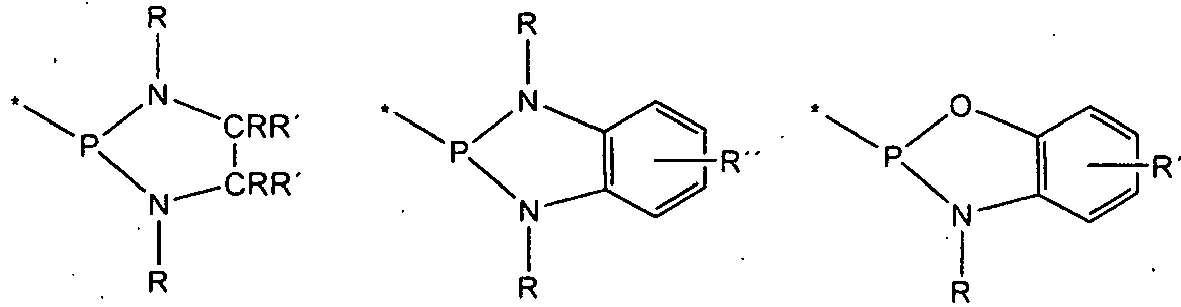


- Zu beachten ist hierbei, dass die dargestellten Ringsysteme über die mit "*" gekennzeichnete Bindung an E gebunden sind
- Grundsätzlich kann es sich bei der Metallkomplexverbindung um einen einkernigen oder mehrkernigen Metallkomplex handeln. Bevorzugt weist der Metallkomplex zwischen 2 und 6 Metallzentren auf.
- Grundsätzlich kann es sich bei der Metallkomplexverbindung um einen Kupfer-, Silber-, Gold-, Palladium-, Platin-, Rhodium-, Iridium-, Rhenium-, Osmium-, Molybdän-, Wolfram- oder Zink-Komplex oder um einen Komplex mit zwei oder mehr dieser Metalle handeln. Die Metalle liegen in der Regel als Kationen vor und sind 1- bis 6-fach positiv geladen.
- In besonders bevorzugten Ausführungsformen weist die Metallkomplexverbindung Kupfer- oder Silberionen als Zentrum oder Zentren auf, bevorzugt in ionischer Form.
- Besonders bevorzugt umfasst die erfindungsgemäße elektronische Vorrichtung Metallkomplexverbindungen der Formel II

- R1 bis R4 und E definiert sind wie in.Formel I und
- [M]n ein Komplexfragment darstellt mit M = Cu, Ag, Au, Pd, Pt, Rh, Ir, Re, Os, Mo, W oder Zn und
- n = 1 oder eine größere ganze Zahl ist, insbesondere eine ganze Zahl von 1 bis 6 und
- y gleich 1, 2 oder 3 ist.
- Die Variable n ist besonders bevorzugt 1, es handelt sich also bei Metallkomplexverbindungen der Formel II bevorzugt um eine einkernige Komplexverbindung.
- Wenn n > 1 ist, dann umfasst M bevorzugt Cu oder Ag sowie mindestens ein weiteres Metall aus der Gruppe mit Cu, Ag, Au, Pd, Pt, Rh, Ir, Re, Os, Mo, W und Zn.
- Potentielle Koordinationsmöglichkeiten zwischen dem Metallzentrum [M]n und den Donoren P sind als gestrichelte Linien dargestellt.
- Freie Valenzen von [M]n sind bei Bedarf mit überbrückenden und/oder nicht überbrückenden Liganden abgesättigt.
- Unter nicht überbrückenden Liganden sollen vorliegend Liganden verstanden werden, die nicht gleichzeitig an zwei oder mehr Metallzentren binden. Wenngleich solche Liganden nicht strukturbildend sind, können sie einen großen Einfluss auf die Abstände zwischen den Metallzentren eines mehrkernigen Komplexes nehmen, indem sie die Elektronendichten an den Metallzentren erhöhen oder erniedrigen. Wichtig sind die Liganden für die Absättigung der Koordinationssphäre des Metalls oder für den Ladungsausgleich oder für beides. Daher können diese Liganden neutral oder anionisch sein. Weiterhin können die Liganden monodentat oder bidentat sein.
- Geeignete neutrale, monodentate Liganden sind vorzugsweise ausgewählt aus der Gruppe mit Kohlenmonoxid, Stickstoffmonoxid, Nitrilen (RCN), Isonitrilen (RNC) wie z.B. t-Butylisonitril, Cyclohexylisonitril, A-damantylisonitril, Phenylisonitril, Mesitylisonitril und 2,6-Dimethylphenylisonitril, Ethern wie z. B. Dimethylether und Diethylether, Seleniden, Aminen wie z. B. Trimethylamin, Triethylamin und Morpholin, Iminen (RN=CR'), Phosphinen wie z. B Triphenylphosphin, Phosphiten wie z.B. Trimethylphosphit, Arsinen, wie z.B. Trifluorarsin, Trimethylarsin und Triphenylarsin, Stibinen wie z.B. Trifluorstibin oder Triphenylstibin und stickstoffhaltigen Heterocyclen wie z.B. Pyridin, Pyridazin, Pyrazin, Pyrimidin und Triazin.
- Geeignete anionische, monodentate Liganden sind vorzugsweise ausgewählt aus der Gruppe mit Hydrid, Deuterid, den Halogeniden F, Cl, Br und I, Azid, Alkylacetyliden, Aryl- bzw. Heteroarylacetyliden, Alkyl, Aryl und Heteroaryl, wie sie oben definiert wurden, Hydroxid, Cyanid, Cyanat, Isocyanat, Thiocyanat, Isothiocyanat, aliphatischen oder aromatischen Alkoholaten, wie z.B. Methanolat, Ethanolat, Propanolat und Phenolat, aliphatischen oder aromatischen Thioalkoholaten wie z.B. Methanthiolat, Ethanthiolat, Propanthiolat und Thiophenolat, Amiden, wie z.B. Dimethylamid, Diethylamid und Morpholid, Carboxylaten, wie z.B. Acetat, Trifluoracetat, Propionat und Benzoat, anionischen, stickstoffhaltigen Heterocyclen wie z.B. Pyrrolid, Imidazolid, Pyrazolid, aliphatischen und aromatischen Phosphiden oder aliphatischen oder aromatischen Seleniden.
- Geeignete di- bzw. trianionische Liganden sind beispielsweise O2-, S2- oder N3-.
- Als Ligand geeignete neutrale oder mono- oder dianionische bidentate Liganden sind vorzugsweise ausgewählt aus der Gruppe mit Diaminen wie z.B. Ethylendiamin, N,N,N',N'-Tetramethylethylendiamin, Propylendiamin, N,N,N',N'-Tetramethylpropylendiamin, cis- oder trans-Diaminocyclohexan, cis- oder trans-N,N,N',N'-Tetramethyldiaminocyclohexan, Iminen wie z.B. 2-[1-(Phenylimino)ethyl]pyridin, 2-[1-(2-Methylphenylimino)-ethyl]pyridin oder 2-[1-(Ethylimino)ethyl]pyridin, Diiminen wie z.B. 1,2-Bis(methylimino)ethan, 1,2-Bis(ethylimino)ethan, 1,2-Bis(isopropylimino)ethan, 2,3-Bis(methyl-imino)-butan, 2,3-Bis(isopropyl-imino)butan oder 1,2-Bis(2-methylphenylimino)ethan, Heterocyclen enthaltend zwei Stickstoffatome wie z.B. 2,2-bipyridin oder o-Phenanthrolin, Diphosphinen wie z.B. Bis(diphenylphosphino)methan, Bis(diphenylphosphino)ethan, Bis(dimethylphosphino)methan, Bis(dimethylphosphino)ethan, Bis-(diethylphosphino)methan oder Bis(diethylphosphino)ethan, 1,3-Diketonaten abgeleitet von 1,3-Diketonen wie z.B. Acetylaceton, Benzoylaceton, 1,5-Diphenylacetylaceton, Dibenzoylmethan und Bis(1,1,1-trifluoracetyl)methan, 3-Ketonaten abgeleitet von 3-Ketoestern wie z.B. Acetessigsäureethylester, Carboxylate abgeleitet von Aminocarbonsäuren wie z.B. Pyridin-2-carbonsäure, Chinolin-2-carbonsäure, Glycin, N,N-Dimethylglycin, Alanin, N,N-Dimethylaminoalanin, Salicyliminaten abgeleitet von Salicyliminen wie z.B. Methylsalicylimin, Ethylsalicylimin, Phenylsalicylimin, Dialkoholaten abgeleitet von Dialkoholen wie z.B. Ethylenglykol, 1,3-Propylenglykol und Dithiolaten abgeleitet von Dithiolen wie z.B. 1,2-Ethylendithiol und 1,3-Propylendithiol.
- Eingesetzt können weiterhin auch bidentate monoanionische Liganden, welche mit dem Metall einen cyclometallierten Fünfring oder Sechsring mit mindestens einer Metall-Kohlenstoff-Bindung aufweisen, insbesondere einen cyclometallierten Fünfring. Dies sind insbesondere Liganden, wie sie allgemein auf dem Gebiet der phosphoreszierenden Metallkomplexe für organische Elektrolumineszenzvorrichtungen verwendet werden, also Liganden vom Typ Phenylpyridin, Naphthylpyridin, Phenylchinolin, Phenylisochinolin, etc., welche jeweils substituiert oder unsubstituiert sein können. Dem Fachmann auf dem Gebiet der phosphoreszierenden Elektrolumineszenzvorrichtungen sind eine Vielzahl derartiger Liganden bekannt, und er kann ohne erfinderisches Zutun weitere derartige Liganden als Ligand auswählen.
- Unter überbrückenden Liganden sollen vorliegend Liganden verstanden werden, die gleichzeitig an zwei oder mehr Metallzentren binden und damit strukturbildend sind. Diese finden somit insbesondere Anwendung, wenn der erfindungsgemäß verwendete Komplex ein mehrkerniger ist. Geeignete überbrückende Liganden weisen in der Regel mindestens zwei Donorgruppen sowie ein die Donorgruppen verbindendes Brückenfragment auf. Bei der Donorgruppe handelt es sich um ein Atom oder eine Atomgruppe, die an das Metallatom bindet. Beide Donorgruppen können gleich oder verschieden sein, es können also auch asymmetrische Liganden verwendet werden
- Auch überbrückende Liganden können entweder neutral oder anionisch sein. In letzterem Fall tragen entweder die Donorgruppen eine negative Ladung oder das Brückenfragment.
- Neutrale, überbrückende Liganden weisen als Donorgruppen insbesondere Gruppen aus der Reihe mit R2N-, R2P-, R2As-, R2N-, CN-, NC-, RO-, RS-, RSe- und RN= auf. ("-" oder "=" bezeichnet den Bindungsmodus, mit dem die Donorgruppe an die Brücke gebunden ist, R bevorzugt einen C1- bis C40-Kohlenwasserstoff, wie er oben definiert wurde). Als Brückenfragment kommt ebenfalls ein Kohlenwasserstoff in Frage, wie er bereits beschrieben wurde, bevorzugt mit maximal 6 C-Atomen.
- Bei anionischen, überbrückenden Liganden sind eine oder beide Donorgruppen negativ geladen, oder das Brückenfragment trägt die Ladung. Häufig verwendete anionische Donorgruppen sind: O-, NR- oder C≡C-.Beispiele für anionische, überbrückende Liganden sind beispielsweise


- In diesen Formeln stehen R und R' bevorzugt für den oben definierten C1-C40 Kohlenwasserstoff.
- Beispielhaft für einen besonders bevorzugten mehrkernigen Komplex, in dem zwei Metallzentren M über verbrückende Liganden verbunden sind, ist der Metallkomplex der Formel III zu nennen:

- In dieser Formel sind R1 bis R4, M und E definiert sind wie in Formel II. Bei den Liganden L1 und L2 handelt es sich um überbrückende Liganden.
- Besonders bevorzugt werden als Metallkomplexe organische Übergangsmetallverbindungen gewählt, die einen ΔE-Abstand zwischen dem untersten Triplett-Zustand und dem darüberliegenden Singulett-Zustand zwischen 50 cm-1 und 3.000 cm-1 aufweisen, also diesbezüglich die gleichen Eigenschaften aufweisen, wie die in der
WO 2010/006681 beschriebenen Komplexe. Betreffend die Berechnung bzw. Messung des Energieabstandes ΔE wird auf die diesbezüglichen Ausführungen in derWO 2010/006681 verwiesen. - Bei der erfindungsgemäßen Vorrichtung handelt es sich insbesondere um eine Vorrichtung aus der Gruppe bestehend aus organischen Elektrolumineszenzvorrichtungen (OLEDs), lichtemittierenden elektrochemischen Zellen (LEECs), organischen Solarzellen (OSCs), organischen Feldeffekttransistoren und organischen Lasern. Weitere in Frage kommende Anwendungsfelder sind OLED-Sensoren, insbesondere nicht hermetisch nach außen abgeschirmte Gas- und Dampf-Sensoren.
- Insbesondere wenn es sich bei der erfindungsgemäßen elektronischen Vorrichtung um eine organische Elektrolumineszenzvorrichtung handelt, ist es bevorzugt, dass die Vorrichtung die Metallkomplexverbindung als Bestandteil einer Emitterschicht umfasst. Der Anteil des Metallkomplexes in der Emitterschicht liegt in diesem Fall bevorzugt zwischen 0,1 und 50 Gew.-%.
- OLEDs sind bekanntlich aus mehreren Schichten aufgebaut. Meist befindet sich auf einem Substrat wie einer Glasscheibe eine schichtartige Anode, beispielsweise bestehend aus Indium-Zinn-Oxid (ITO). Auf dieser ist eine Lochleitungsschicht (engl. "hole transport layer", HTL) angeordnet. Zwischen der Anode und der Lochleitungsschicht kann sich gegebenenfalls noch eine Schicht aus PEDOT/PSS (Poly(3,4-ethylendioxythiophen)polystyrolsulfonat) befinden, die zur Absenkung der Injektionsbarriere für Löcher dient und die Eindiffusion von Indium in den Übergang verhindert. Auf die Lochleitungsschicht ist in aller Regel die Emitterschicht aufgebracht, die im vorliegenden Fall die oben beschriebene Metallkomplexverbindung mit dem mindestens einen anionischen Liganden enthält. Unter Umständen kann die Emitterschicht auch aus diesem Komplex bestehen. Auf die Emitterschicht wird abschließend eine Elektronenleitungsschicht (engl. "electron transport layer", ETL) aufgebracht. Darauf wird wiederum eine Kathodenschicht, beispielsweise bestehend aus einem Metall oder einer Metalllegierung, im Hochvakuum aufgedampft. Als Schutzschicht und zur Verringerung der Injektionsbarriere für Elektronen kann zwischen Kathode und der ETL gegebenenfalls noch eine dünne Schicht aus Lithiumfluorid, Cäsiumfluorid oder Silber aufgedampft werden.
- Die Elektronen (= negative Ladung) wandern im Betrieb von der Kathode in Richtung Anode, welche die Löcher (= positive Ladung) bereitstellt. Löcher und Elektronen treffen sich im Idealfall in der Emitterschicht, weshalb diese auch als Rekombinationsschicht bezeichnet wird. Elektronen und Löcher bilden einen gebundenen Zustand, den man als Exziton bezeichnet. Von einem Exziton kann durch Energieübertrag eine Metallkomplexverbindung wie die vorliegend beschriebene angeregt werden. Diese kann in den Grundzustand übergehen und dabei ein Photon emittieren. Die Farbe des ausgesendeten Lichts hängt dabei vom Energieabstand zwischen angeregtem und Grundzustand ab und kann durch Variation des Komplexes bzw. der Komplexliganden gezielt variiert werden.
- Insbesondere wenn es sich bei der erfindungsgemäßen Vorrichtung um eine organische Solarzelle handelt, ist es bevorzugt, dass die Vorrichtung die Metallkomplexverbindung als Bestandteil einer Absorberschicht umfasst, wobei der Anteil der Metallkomplexverbindung in der Absorberschicht bevorzugt zwischen 30 und 100 Gew.-% beträgt. Bei einer organischen Solarzelle handelt es sich um eine Solarzelle, die zumindest überwiegend aus organischen Werkstoffen, d.h. aus KohlenwasserstoffVerbindungen, besteht.
- Wie bei OLEDs sind auch bei organischen Solarzellen zwei Elektroden vorgesehen. Zwischen diesen ist die Absorberschicht angeordnet, in welcher der in der vorliegenden Anmeldung beschriebene Metallkomplex zum Einsatz kommt.
- Wie bereits erwähnt, können die vorliegend beschriebenen Metallkomplexverbindungen Licht emittieren. Durch Variation der Liganden lässt sich dabei der ΔE-Abstand zwischen dem untersten Triplett-Zustand dem darüberliegenden Singulett-Zustand variieren, so dass es grundsätzlich möglich ist, die Wellenlänge des emittierten Lichtes auf definierte Werte einzustellen, insbesondere auch auf sehr kurzwellige Werte, so dass blaues Licht emittiert wird. Insbesondere mit Kupferkomplexen, die den beschriebenen Komplexliganden aufweisen, wurden diesbezüglich hervorragende Ergebnisse erzielt.
- Die beschriebenen Komplexverbindungen sind in der Regel in organischen Lösungsmitteln wie Benzol oder Toluol sehr gut löslich. Das eröffnet die Möglichkeit, ein grundsätzlich beliebiges Substrat mit den Komplexverbindungen zu bedrucken. Entsprechend ist auch ein Verfahren zur Herstellung einer elektronischen Vorrichtung wie den vorstehend beschriebenen Gegenstand der vorliegenden Erfindung, bei dem die beschriebene Metallkomplexverbindung mit dem mindestens einen anionischen Liganden der Formel I auf ein Substrat aufgedruckt wird.
- Weitere Merkmale der Erfindung ergeben sich aus der nachfolgenden Beschreibung bevorzugter Ausführungsformen. Es sei an dieser Stelle explizit betont, dass sämtliche in der vorliegenden Anmeldung beschriebenen fakultativen Aspekte der erfindungsgemäßen Vorrichtungen oder der erfindungsgemäßen Verfahren jeweils für sich allein oder in Kombination mit einem oder mehreren der weiteren beschriebenen fakultativen
- Aspekte bei einer Ausführungsform der Erfindung verwirktlicht sein können. Die nachfolgende Beschreibung von bevorzugten Ausführungsformen dient lediglich zur Erläuterung und zum besseren Verständnis der Erfindung und ist in keiner Weise einschränkend zu verstehen.
- Es wurden Komplexverbindungen mit folgenden Formeln synthetisiert:
- (1) [Cu2(Ph2PCPhPPh2)2(NC4H8)2]
- (2) [Cu(Ph2PCPhPPh2)(Ph2PC6H4PPh2)]
- (3) [Cu(Ph2PCPhPPh2)(dppbe)]
- (4) [Cu(Ph2PCPhPPh2)(PN)]
- (5) [{Cu(Ph2PCPhPPh2)(dmpm)}2]
- (6) [{Cu(Ph2PCPhPPh2)(dmpe)}2]
- (7) [Cu2{PPh2C(CN)PPh2}2phen2]
- (8) [Ag{PPh2C(CN)PPh2}n]
- (9) [Au2[PPh2C(CN)PPh2}2]
- (10) [Cu2{PPh2C(Ph)PPh(C6H4NMe2}2]
- Die anhand von Röntgenstrukturdaten ermittelte Struktur des zweikernigen Kupferkomplexes (1) ist in
Fig. 1 dargestellt. Links ist die komplette Molekülstruktur dargestellt, rechts nur das Gerüst des Komplexes ohne Wasserstoffatome und ohne Phenylgruppen. - Die anhand von Röntgenstrukturdaten ermittelte Struktur des einkernigen Kupferkomplexes (2) ist in
Fig. 2 dargestellt. Links ist die komplette Molekülstruktur dargestellt, rechts nur das Gerüst des Komplexes ohne Wasserstoffatome und ohne Phenylgruppen. -
Fig. 3 zeigt links die Strukturformel des einkernigen Kupferkomplexes (3), wobei dppbe für den zweizähnigen Ligand 1,2-Bis(diphenylphosphinobenzol)ethan steht. Rechts ist das Emissionspektrum des Komplexes mit einem Intensitäts-Maximum bei etwa 550 nm dargestellt. -
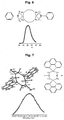
Fig. 4 zeigt links die Strukturformel des einkernigen Kupferkomplexes (4). Rechts ist das Emissionspektrum des Komplexes mit einem Intensitäts-Maximum bei etwa 480 nm dargestellt. -
Fig. 5 zeigt oben die Strukturformel des zweikernigen Kupferkomplexes (5), wobei dmpm für den zweizähnigen Ligand Bis(dimethylphosphino)-methan steht. Unten ist das Emissionspektrum des Komplexes mit einem Intensitäts-Maximum bei etwa 520 nm dargestellt. -
Fig. 6 zeigt oben die Strukturformel des zweikernigen Kupferkomplexes (6), wobei dmpe für den zweizähnigen Ligand Bis(dimethylphosphino)-ethan steht. Unten ist das Emissionspektrum des Komplexes mit einem Intensitäts-Maximum bei etwa 515 nm dargestellt. -
Fig. 7 zeigt oben links die anhand von Röntgenstrukturdaten ermittelte Struktur des zweikernigen Kupferkomplexes (7), wobei phen für den zweizähnigen Ligand Phenanthrolin steht. Oben rechts ist die Strukturformel abgebildet. Unten ist das Emissionspektrum des Komplexes mit einem Intensitäts-Maximum bei etwa 515 nm dargestellt. -
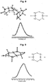
Fig. 8 zeigt oben links die anhand von Röntgenstrukturdaten ermittelte Struktur des zweikernigen Silberkomplexes (8). Oben rechts ist die Strukturformel abgebildet. Unten ist das Emissionspektrum des Komplexes mit einem Intensitäts-Maximum bei etwa 525 nm dargestellt. -
Fig. 9 zeigt oben links die anhand von Röntgenstrukturdaten ermittelte Struktur des zweikernigen Goldkomplexes (9). Oben rechts ist die Strukturformel abgebildet. Unten ist das Emissionspektrum des Komplexes mit einem Intensitäts-Maximum bei etwa 520 nm dargestellt. -
Fig. 10 zeigt links die Strukturformel des zweikernigen Kupferkomplexes (10). Rechts ist das Emissionspektrum des Komplexes mit einem Intensitäts-Maximum bei etwa 620 nm dargestellt. - Alle diese Komplexe zeigten ein hervorragendes Abklingverhalten und waren leicht herstellbar. Nachfolgend wird anhand von zwei Beispielen der allgeimene Syntheseweg beschrieben.
- Kupferamid [Cu(NCH2)4] wurde mit einem Äquivalent des Liganden [RCH(PPh2)] in Toluol unter Rühren vorgelegt. Anschließend erfolgte die Zugabe des zweizähnigen Liganden 1,2-Bis(diphenylphosphinobenzol)-ethan (dppbe). Nach mehrmaliger Rekristallisation aus Toluol konnte der Kupferkomplex (3) in kristalliner Form gewonnen und der Röntgenstrukturanalyse zugeführt werden.
- Kupferamid [Cu(NCH2)4] wurde mit einem Äquivalent des Liganden [Ph2PPhCHPPh(C6H4NMe2)] in Toluol unter Rühren vorgelegt. Nach Überschichten dieser Reaktionslösung mit n-Hexan konnte der zweizähnige Kupferkomplex (10) in kristalliner Form gewonnen und der Röntgenstrukturanalyse zugeführt werden.
Claims (13)
- Elektronische Vorrichtung, enthaltend eine Metallkomplexverbindung mit mindestens einem anionischen Liganden mit zwei P-Donoren mit der Formel I
 • R1 bis R4 unabhängig voneinander ein Atom oder Rest aus der Gruppe umfassend Wasserstoff, ein Halogen, R-, RO-, RS-, RCO-, RCOO-, RNH-, R2N-, RCONR- und -Si(R)X(OR)3-X mit R = ein C1-C40-Kohlenwasserstoff und X = 1, 2 oder 3 sind und• E ein Kohlenstoff oder ein Bor ist, wobei- an den Kohlenstoff gegebenenfalls ein Atom oder Rest aus der Gruppe mit Wasserstoff, Halogen, -CN, R-, RO-, RS-, RCO-, RCOO-, RNH-, R2N-, RCONR- und -Si(R)X(OR)3-X mit R = dem C1-C40-Kohlenwasserstoff und X = 1, 2 oder 3 gebunden ist, und- an das Bor gegebenenfalls zwei Reste aus der Gruppe mit Halogen, R-, RO-, RS-, RCO-, RCOO-, RNH-, R2N-, RCONR- und -Si(R)X(OR)3-X mit R = dem C1-C40-Kohlenwasserstoff und X = 1, 2 oder 3 gebunden sind.
 - Vorrichtung nach Anspruch 1, dadurch gekennzeichnet, dass der C1- bis C40-Kohlenwasserstoff R ein Alkyl-, Cycloalkyl-, Alkenyl-, Cycloalkenyl-, Alkinyl-, Cycloalkinyl-, Alkylcycloalkyl-, Heteroalkyl-, Heterocycloalkyl-, Heteroalkylcycloalkyl-, Aryl-, Heteroaryl-, Aralkyl- oder Heteroaralkyl-Rest ist, von denen jeder in bevorzugten Ausführungsformen eine oder mehrere Halogen-, Hydroxy-, Thiol-, Carbonyl-, Keto-, Carboxyl-, Cyano-, Sulfon-, Nitro-, Amino- und/ oder Iminofunktionen aufweisen kann.
- Vorrichtung nach einem der Ansprüche 1 oder 2, dadurch gekennzeichnet, dass mindestens eines der beiden P ein Ringatom eines Ringsystems aromatischer oder nichtaromatischer Natur ist (welches die Reste R1 und R2 und/oder R3 und R4 umfasst).
- Vorrichtung nach einem der Ansprüche 1 bis 3, dadurch gekennzeichnet, dass die Metallkomplexverbindung einkernig oder mehrkernig ist, bevorzugt ein bis sechs Metallzentren aufweist.
- Vorrichtung nach einem der vorhergehenden Ansprüche, dadurch gekennzeichnet, dass die Metallkomplexverbindung zumindest eines der Metalle Cu, Ag, Au, Pd, Pt, Rh, Ir, Re, Os, Mo, W und Zn in bevorzugt ionischer Form umfasst.
- Vorrichtung nach Anspruch 5, dadurch gekennzeichnet, dass die Metallkomplexverbindung ein Cu- oder ein Ag-Ion sowie mindestens ein weiteres Metall aus der Gruppe mit Cu, Ag, Au, Pd, Pt, Rh, Ir, Re, Os, Mo, W oder Zn umfasst.
- Vorrichtung nach einem der vorhergehenden Ansprüche, dadurch gekennzeichnet, dass die Metallkomplexverbindung die Formel II
 • R1 bis R4 und E definiert sind wie in Formel I,• [M]n ein Komplexfragment darstellt mit M = mindestens ein Metall aus der Gruppe mit Cu, Ag, Au, Pd, Pt, Rh, Ir, Re, Os, Mo, W und Zn,• n gleich 1 oder eine höhere ganze Zahl ist und• y gleich 1, 2 oder 3 ist.
 - Vorrichtung nach einem der vorhergehenden Ansprüche, dadurch gekennzeichnet, dass die Metallkomplexverbindung einen ΔE-Abstand zwischen dem untersten Triplett-Zustand und dem darüber liegenden Singulett-Zustand zwischen 50 cm-1 und 3000 cm-1 aufweist.
- Vorrichtung nach einem der vorhergehenden Ansprüche, ausgewählt aus der Gruppe bestehend aus organischen Elektrolumineszenzvorrichtungen (OLEDs), lichtemittierenden elektrochemischen Zellen (LEECs), organischen Solarzellen (OSCs), organischen Feldeffekttransistoren und organischen Lasern.
- Vorrichtung nach einem der vorhergehenden Ansprüche, dadurch gekennzeichnet, dass sie die Metallkomplexverbindung als Bestandteil einer Emitterschicht umfasst, wobei der Anteil des Metallkomplexes in der Emitterschicht bevorzugt zwischen 0.1 und 50 Gew.-% beträgt.
- Vorrichtung nach einem der vorhergehenden Ansprüche, dadurch gekennzeichnet, dass sie die Metallkomplexverbindung als Bestandteil einer Absorberschicht umfasst, wobei der Anteil des Metallkomplexes in der Absorberschicht bevorzugt zwischen 30 und 100 Gew.-% beträgt.
- Verfahren zur Erzeugung von blauer Emission unter Verwendung einer Metallkomplexverbindung mit einem Liganden mit zwei P-Donoren mit der Formel I.
- Verfahren zur Herstellung einer elektronischen Vorrichtung nach einem der vorhergehenden Ansprüche, dadurch gekennzeichnet, dass die Metallkomplexverbindung mit dem mindestens einen anionischen Liganden der Formel I auf ein Substrat aufgedruckt wird.
Applications Claiming Priority (2)
| Application Number | Priority Date | Filing Date | Title |
|---|---|---|---|
| DE102011079847A DE102011079847A1 (de) | 2011-07-26 | 2011-07-26 | Komplexverbindungen mit anionischen Liganden mit zwei P-Donoren und ihre Verwendung im opto-elektronischen Bereich |
| PCT/EP2012/064126 WO2013014049A1 (de) | 2011-07-26 | 2012-07-18 | Komplexverbindungen mit anionischen liganden mit zwei p-donoren und ihre verwendung im opto-elektronischen bereich |
Publications (2)
| Publication Number | Publication Date |
|---|---|
| EP2737004A1 EP2737004A1 (de) | 2014-06-04 |
| EP2737004B1 true EP2737004B1 (de) | 2016-05-04 |
Family
ID=46604278
Family Applications (1)
| Application Number | Title | Priority Date | Filing Date |
|---|---|---|---|
| EP12743106.2A Not-in-force EP2737004B1 (de) | 2011-07-26 | 2012-07-18 | Komplexverbindungen mit anionischen liganden mit zwei p-donoren und ihre verwendung im opto-elektronischen bereich |
Country Status (5)
| Country | Link |
|---|---|
| US (1) | US9425398B2 (de) |
| EP (1) | EP2737004B1 (de) |
| JP (1) | JP2014527292A (de) |
| DE (1) | DE102011079847A1 (de) |
| WO (1) | WO2013014049A1 (de) |
Families Citing this family (1)
| Publication number | Priority date | Publication date | Assignee | Title |
|---|---|---|---|---|
| DE102009030475A1 (de) * | 2009-06-24 | 2011-01-05 | Hartmut Prof. Dr. Yersin | Kupfer-Komplexe für optoelektronische Anwendungen |
Family Cites Families (21)
| Publication number | Priority date | Publication date | Assignee | Title |
|---|---|---|---|---|
| JP4067286B2 (ja) | 2000-09-21 | 2008-03-26 | 富士フイルム株式会社 | 発光素子及びイリジウム錯体 |
| JP4574936B2 (ja) | 2001-08-31 | 2010-11-04 | 日本放送協会 | 燐光発光性化合物及び燐光発光性組成物 |
| DE10143353A1 (de) | 2001-09-04 | 2003-03-20 | Covion Organic Semiconductors | Konjugierte Polymere enthaltend Spirobifluoren-Einheiten und deren Verwendung |
| JP2003212886A (ja) | 2002-01-24 | 2003-07-30 | Sumitomo Chem Co Ltd | アミジン化合物および複核遷移金属錯体 |
| US6963005B2 (en) | 2002-08-15 | 2005-11-08 | E. I. Du Pont De Nemours And Company | Compounds comprising phosphorus-containing metal complexes |
| GB0226010D0 (en) | 2002-11-08 | 2002-12-18 | Cambridge Display Tech Ltd | Polymers for use in organic electroluminescent devices |
| US20050244672A1 (en) | 2004-04-30 | 2005-11-03 | Chi-Ming Che | Organic light-emitting devices |
| JP4496357B2 (ja) | 2004-06-04 | 2010-07-07 | 独立行政法人産業技術総合研究所 | フッ素置換イリジウム錯体およびこれを用いた発光材料 |
| JP4764047B2 (ja) * | 2005-03-31 | 2011-08-31 | キヤノン株式会社 | 発光素子 |
| US7462406B2 (en) | 2005-11-15 | 2008-12-09 | Eastman Kodak Company | OLED devices with dinuclear copper compounds |
| KR101313094B1 (ko) | 2006-01-24 | 2013-12-31 | 삼성디스플레이 주식회사 | 1,8-나프탈이미드기를 가진 고분자 및 상기 고분자를포함하는 유기 발광 소자 |
| US7683183B2 (en) | 2006-07-28 | 2010-03-23 | California Institute Of Technology | Emissive monomeric metal complexes |
| DE102006038683A1 (de) | 2006-08-17 | 2008-02-21 | Merck Patent Gmbh | Konjugierte Polymere, deren Darstellung und Verwendung |
| JP2008074905A (ja) * | 2006-09-19 | 2008-04-03 | Idemitsu Kosan Co Ltd | 有機エレクトロルミネッセンス素子 |
| JP5282260B2 (ja) | 2006-11-27 | 2013-09-04 | ユー・ディー・シー アイルランド リミテッド | 有機電界発光素子 |
| DE102008033563A1 (de) | 2008-07-17 | 2010-01-21 | Merck Patent Gmbh | Komplexe mit kleinen Singulett-Triplett-Energie-Abständen zur Verwendung in opto-elektronischen Bauteilen (Singulett-Harvesting-Effekt) |
| DE102008048336A1 (de) | 2008-09-22 | 2010-03-25 | Merck Patent Gmbh | Einkernige neutrale Kupfer(I)-Komplexe und deren Verwendung zur Herstellung von optoelektronischen Bauelementen |
| JP2010093181A (ja) * | 2008-10-10 | 2010-04-22 | Canon Inc | 有機発光素子 |
| JP5695314B2 (ja) * | 2008-12-01 | 2015-04-01 | 住友化学株式会社 | 発光性銀錯体 |
| CN101747375B (zh) | 2008-12-08 | 2013-08-14 | 中国科学院福建物质结构研究所 | 8-膦基喹啉衍生物为配体的铜(i)磷光配合物及其应用 |
| US8580394B2 (en) | 2009-11-19 | 2013-11-12 | Universal Display Corporation | 3-coordinate copper(I)-carbene complexes |
-
2011
- 2011-07-26 DE DE102011079847A patent/DE102011079847A1/de not_active Withdrawn
-
2012
- 2012-07-18 WO PCT/EP2012/064126 patent/WO2013014049A1/de not_active Ceased
- 2012-07-18 JP JP2014522039A patent/JP2014527292A/ja not_active Ceased
- 2012-07-18 EP EP12743106.2A patent/EP2737004B1/de not_active Not-in-force
- 2012-07-18 US US14/234,857 patent/US9425398B2/en not_active Expired - Fee Related
Also Published As
| Publication number | Publication date |
|---|---|
| US20140203225A1 (en) | 2014-07-24 |
| JP2014527292A (ja) | 2014-10-09 |
| US9425398B2 (en) | 2016-08-23 |
| DE102011079847A1 (de) | 2013-01-31 |
| EP2737004A1 (de) | 2014-06-04 |
| WO2013014049A1 (de) | 2013-01-31 |
Similar Documents
| Publication | Publication Date | Title |
|---|---|---|
| DE102011079856A1 (de) | Komplexverbindungen mit einem Liganden mit einem N- und einem P-Donor und ihre Verwendung im opto-elektronischen Bereich | |
| EP2297276B1 (de) | Komplexe zur verwendung in opto-elektronischen bauteilen | |
| EP3046927B1 (de) | Polycyclische phenyl-pyridin iridiumkomplexe und derivate davon für oled | |
| EP2311112B1 (de) | Elektronische vorrichtung enthaltend metallkomplexe mit isonitrilliganden | |
| DE102010027317A1 (de) | Metallkomplexe | |
| DE102010027319A1 (de) | Metallkomplexe | |
| DE102010005463A1 (de) | Blau-Licht-Emitter mit Singulett-Harvesting-Effekt zur Verwendung in OLEDs und anderen organisch-elektronischen Vorrichtungen | |
| DE102009030475A1 (de) | Kupfer-Komplexe für optoelektronische Anwendungen | |
| DE102007031261A1 (de) | Lumineszierende Metallkomplexe mit sperrigen Hilfsliganden | |
| EP2906575A1 (de) | Metallkomplexe | |
| DE102008013691A1 (de) | Verwendung von Zusammensetzungen neutraler Übergangsmetallkomplexe in opto-elektronischen Bauelementen | |
| DE102015112133A1 (de) | Metallkomplexverbindung und organisches lichtemittierendes Bauelement | |
| EP2984093B1 (de) | Metallkomplexe und ihre verwendung in elektronischen vorrichtungen | |
| DE102011079857B4 (de) | Komplexverbindungen mit vierzähnigen Liganden und ihre Verwendung im opto-elektronischen Bereich | |
| WO2014044347A1 (de) | Metallkomplexe | |
| DE102011079846B4 (de) | Komplexverbindungen mit einem mehrzähnigen, asymmetrischen Liganden und ihre Verwendung im opto-elektronischen Bereich | |
| DE102011079847A1 (de) | Komplexverbindungen mit anionischen Liganden mit zwei P-Donoren und ihre Verwendung im opto-elektronischen Bereich | |
| DE102015112134A1 (de) | Metallkomplexverbindung und organisches lichtemittierendes Bauelement | |
| DE102012021650A1 (de) | Metallkomplexe | |
| DE102010007825A1 (de) | Verwendung von Gold-Komplexen in opto-elektronischen Vorrichtungen | |
| DE102014012818A1 (de) | Metallkomplexe |
Legal Events
| Date | Code | Title | Description |
|---|---|---|---|
| PUAI | Public reference made under article 153(3) epc to a published international application that has entered the european phase |
Free format text: ORIGINAL CODE: 0009012 |
|
| 17P | Request for examination filed |
Effective date: 20131210 |
|
| AK | Designated contracting states |
Kind code of ref document: A1 Designated state(s): AL AT BE BG CH CY CZ DE DK EE ES FI FR GB GR HR HU IE IS IT LI LT LU LV MC MK MT NL NO PL PT RO RS SE SI SK SM TR |
|
| DAX | Request for extension of the european patent (deleted) | ||
| 17Q | First examination report despatched |
Effective date: 20150326 |
|
| GRAP | Despatch of communication of intention to grant a patent |
Free format text: ORIGINAL CODE: EPIDOSNIGR1 |
|
| RIC1 | Information provided on ipc code assigned before grant |
Ipc: H01L 51/00 20060101ALI20151103BHEP Ipc: C09K 11/06 20060101AFI20151103BHEP Ipc: H01L 51/50 20060101ALI20151103BHEP Ipc: H05B 33/14 20060101ALI20151103BHEP |
|
| INTG | Intention to grant announced |
Effective date: 20151120 |
|
| GRAS | Grant fee paid |
Free format text: ORIGINAL CODE: EPIDOSNIGR3 |
|
| GRAA | (expected) grant |
Free format text: ORIGINAL CODE: 0009210 |
|
| AK | Designated contracting states |
Kind code of ref document: B1 Designated state(s): AL AT BE BG CH CY CZ DE DK EE ES FI FR GB GR HR HU IE IS IT LI LT LU LV MC MK MT NL NO PL PT RO RS SE SI SK SM TR |
|
| REG | Reference to a national code |
Ref country code: GB Ref legal event code: FG4D Free format text: NOT ENGLISH |
|
| REG | Reference to a national code |
Ref country code: CH Ref legal event code: EP |
|
| REG | Reference to a national code |
Ref country code: AT Ref legal event code: REF Ref document number: 796913 Country of ref document: AT Kind code of ref document: T Effective date: 20160515 |
|
| REG | Reference to a national code |
Ref country code: IE Ref legal event code: FG4D Free format text: LANGUAGE OF EP DOCUMENT: GERMAN |
|
| REG | Reference to a national code |
Ref country code: DE Ref legal event code: R096 Ref document number: 502012007010 Country of ref document: DE |
|
| REG | Reference to a national code |
Ref country code: NL Ref legal event code: MP Effective date: 20160504 |
|
| REG | Reference to a national code |
Ref country code: LT Ref legal event code: MG4D |
|
| PG25 | Lapsed in a contracting state [announced via postgrant information from national office to epo] |
Ref country code: NL Free format text: LAPSE BECAUSE OF FAILURE TO SUBMIT A TRANSLATION OF THE DESCRIPTION OR TO PAY THE FEE WITHIN THE PRESCRIBED TIME-LIMIT Effective date: 20160504 Ref country code: LT Free format text: LAPSE BECAUSE OF FAILURE TO SUBMIT A TRANSLATION OF THE DESCRIPTION OR TO PAY THE FEE WITHIN THE PRESCRIBED TIME-LIMIT Effective date: 20160504 Ref country code: FI Free format text: LAPSE BECAUSE OF FAILURE TO SUBMIT A TRANSLATION OF THE DESCRIPTION OR TO PAY THE FEE WITHIN THE PRESCRIBED TIME-LIMIT Effective date: 20160504 Ref country code: NO Free format text: LAPSE BECAUSE OF FAILURE TO SUBMIT A TRANSLATION OF THE DESCRIPTION OR TO PAY THE FEE WITHIN THE PRESCRIBED TIME-LIMIT Effective date: 20160804 |
|
| PGFP | Annual fee paid to national office [announced via postgrant information from national office to epo] |
Ref country code: DE Payment date: 20160712 Year of fee payment: 5 |
|
| PG25 | Lapsed in a contracting state [announced via postgrant information from national office to epo] |
Ref country code: ES Free format text: LAPSE BECAUSE OF FAILURE TO SUBMIT A TRANSLATION OF THE DESCRIPTION OR TO PAY THE FEE WITHIN THE PRESCRIBED TIME-LIMIT Effective date: 20160504 Ref country code: SE Free format text: LAPSE BECAUSE OF FAILURE TO SUBMIT A TRANSLATION OF THE DESCRIPTION OR TO PAY THE FEE WITHIN THE PRESCRIBED TIME-LIMIT Effective date: 20160504 Ref country code: HR Free format text: LAPSE BECAUSE OF FAILURE TO SUBMIT A TRANSLATION OF THE DESCRIPTION OR TO PAY THE FEE WITHIN THE PRESCRIBED TIME-LIMIT Effective date: 20160504 Ref country code: RS Free format text: LAPSE BECAUSE OF FAILURE TO SUBMIT A TRANSLATION OF THE DESCRIPTION OR TO PAY THE FEE WITHIN THE PRESCRIBED TIME-LIMIT Effective date: 20160504 Ref country code: GR Free format text: LAPSE BECAUSE OF FAILURE TO SUBMIT A TRANSLATION OF THE DESCRIPTION OR TO PAY THE FEE WITHIN THE PRESCRIBED TIME-LIMIT Effective date: 20160805 Ref country code: PT Free format text: LAPSE BECAUSE OF FAILURE TO SUBMIT A TRANSLATION OF THE DESCRIPTION OR TO PAY THE FEE WITHIN THE PRESCRIBED TIME-LIMIT Effective date: 20160905 Ref country code: LV Free format text: LAPSE BECAUSE OF FAILURE TO SUBMIT A TRANSLATION OF THE DESCRIPTION OR TO PAY THE FEE WITHIN THE PRESCRIBED TIME-LIMIT Effective date: 20160504 |
|
| PG25 | Lapsed in a contracting state [announced via postgrant information from national office to epo] |
Ref country code: IT Free format text: LAPSE BECAUSE OF FAILURE TO SUBMIT A TRANSLATION OF THE DESCRIPTION OR TO PAY THE FEE WITHIN THE PRESCRIBED TIME-LIMIT Effective date: 20160504 Ref country code: BE Free format text: LAPSE BECAUSE OF NON-PAYMENT OF DUE FEES Effective date: 20160731 |
|
| PG25 | Lapsed in a contracting state [announced via postgrant information from national office to epo] |
Ref country code: DK Free format text: LAPSE BECAUSE OF FAILURE TO SUBMIT A TRANSLATION OF THE DESCRIPTION OR TO PAY THE FEE WITHIN THE PRESCRIBED TIME-LIMIT Effective date: 20160504 Ref country code: CZ Free format text: LAPSE BECAUSE OF FAILURE TO SUBMIT A TRANSLATION OF THE DESCRIPTION OR TO PAY THE FEE WITHIN THE PRESCRIBED TIME-LIMIT Effective date: 20160504 Ref country code: EE Free format text: LAPSE BECAUSE OF FAILURE TO SUBMIT A TRANSLATION OF THE DESCRIPTION OR TO PAY THE FEE WITHIN THE PRESCRIBED TIME-LIMIT Effective date: 20160504 Ref country code: SK Free format text: LAPSE BECAUSE OF FAILURE TO SUBMIT A TRANSLATION OF THE DESCRIPTION OR TO PAY THE FEE WITHIN THE PRESCRIBED TIME-LIMIT Effective date: 20160504 Ref country code: RO Free format text: LAPSE BECAUSE OF FAILURE TO SUBMIT A TRANSLATION OF THE DESCRIPTION OR TO PAY THE FEE WITHIN THE PRESCRIBED TIME-LIMIT Effective date: 20160504 |
|
| REG | Reference to a national code |
Ref country code: DE Ref legal event code: R097 Ref document number: 502012007010 Country of ref document: DE |
|
| PG25 | Lapsed in a contracting state [announced via postgrant information from national office to epo] |
Ref country code: SM Free format text: LAPSE BECAUSE OF FAILURE TO SUBMIT A TRANSLATION OF THE DESCRIPTION OR TO PAY THE FEE WITHIN THE PRESCRIBED TIME-LIMIT Effective date: 20160504 Ref country code: PL Free format text: LAPSE BECAUSE OF FAILURE TO SUBMIT A TRANSLATION OF THE DESCRIPTION OR TO PAY THE FEE WITHIN THE PRESCRIBED TIME-LIMIT Effective date: 20160504 |
|
| REG | Reference to a national code |
Ref country code: CH Ref legal event code: PL |
|
| PLBE | No opposition filed within time limit |
Free format text: ORIGINAL CODE: 0009261 |
|
| STAA | Information on the status of an ep patent application or granted ep patent |
Free format text: STATUS: NO OPPOSITION FILED WITHIN TIME LIMIT |
|
| PG25 | Lapsed in a contracting state [announced via postgrant information from national office to epo] |
Ref country code: MC Free format text: LAPSE BECAUSE OF FAILURE TO SUBMIT A TRANSLATION OF THE DESCRIPTION OR TO PAY THE FEE WITHIN THE PRESCRIBED TIME-LIMIT Effective date: 20160504 |
|
| 26N | No opposition filed |
Effective date: 20170207 |
|
| GBPC | Gb: european patent ceased through non-payment of renewal fee |
Effective date: 20160804 |
|
| PG25 | Lapsed in a contracting state [announced via postgrant information from national office to epo] |
Ref country code: FR Free format text: LAPSE BECAUSE OF NON-PAYMENT OF DUE FEES Effective date: 20160801 Ref country code: CH Free format text: LAPSE BECAUSE OF NON-PAYMENT OF DUE FEES Effective date: 20160731 Ref country code: LI Free format text: LAPSE BECAUSE OF NON-PAYMENT OF DUE FEES Effective date: 20160731 |
|
| REG | Reference to a national code |
Ref country code: FR Ref legal event code: ST Effective date: 20170331 |
|
| REG | Reference to a national code |
Ref country code: IE Ref legal event code: MM4A |
|
| PG25 | Lapsed in a contracting state [announced via postgrant information from national office to epo] |
Ref country code: SI Free format text: LAPSE BECAUSE OF FAILURE TO SUBMIT A TRANSLATION OF THE DESCRIPTION OR TO PAY THE FEE WITHIN THE PRESCRIBED TIME-LIMIT Effective date: 20160504 |
|
| PG25 | Lapsed in a contracting state [announced via postgrant information from national office to epo] |
Ref country code: GB Free format text: LAPSE BECAUSE OF NON-PAYMENT OF DUE FEES Effective date: 20160804 Ref country code: IE Free format text: LAPSE BECAUSE OF NON-PAYMENT OF DUE FEES Effective date: 20160718 |
|
| PG25 | Lapsed in a contracting state [announced via postgrant information from national office to epo] |
Ref country code: LU Free format text: LAPSE BECAUSE OF NON-PAYMENT OF DUE FEES Effective date: 20160718 |
|
| REG | Reference to a national code |
Ref country code: DE Ref legal event code: R119 Ref document number: 502012007010 Country of ref document: DE |
|
| PG25 | Lapsed in a contracting state [announced via postgrant information from national office to epo] |
Ref country code: DE Free format text: LAPSE BECAUSE OF NON-PAYMENT OF DUE FEES Effective date: 20180201 |
|
| PG25 | Lapsed in a contracting state [announced via postgrant information from national office to epo] |
Ref country code: CY Free format text: LAPSE BECAUSE OF FAILURE TO SUBMIT A TRANSLATION OF THE DESCRIPTION OR TO PAY THE FEE WITHIN THE PRESCRIBED TIME-LIMIT Effective date: 20160504 Ref country code: HU Free format text: LAPSE BECAUSE OF FAILURE TO SUBMIT A TRANSLATION OF THE DESCRIPTION OR TO PAY THE FEE WITHIN THE PRESCRIBED TIME-LIMIT; INVALID AB INITIO Effective date: 20120718 |
|
| PG25 | Lapsed in a contracting state [announced via postgrant information from national office to epo] |
Ref country code: MK Free format text: LAPSE BECAUSE OF FAILURE TO SUBMIT A TRANSLATION OF THE DESCRIPTION OR TO PAY THE FEE WITHIN THE PRESCRIBED TIME-LIMIT Effective date: 20160504 Ref country code: IS Free format text: LAPSE BECAUSE OF FAILURE TO SUBMIT A TRANSLATION OF THE DESCRIPTION OR TO PAY THE FEE WITHIN THE PRESCRIBED TIME-LIMIT Effective date: 20160504 Ref country code: MT Free format text: LAPSE BECAUSE OF FAILURE TO SUBMIT A TRANSLATION OF THE DESCRIPTION OR TO PAY THE FEE WITHIN THE PRESCRIBED TIME-LIMIT Effective date: 20160504 |
|
| PG25 | Lapsed in a contracting state [announced via postgrant information from national office to epo] |
Ref country code: BG Free format text: LAPSE BECAUSE OF FAILURE TO SUBMIT A TRANSLATION OF THE DESCRIPTION OR TO PAY THE FEE WITHIN THE PRESCRIBED TIME-LIMIT Effective date: 20160504 |
|
| REG | Reference to a national code |
Ref country code: AT Ref legal event code: MM01 Ref document number: 796913 Country of ref document: AT Kind code of ref document: T Effective date: 20170718 |
|
| PG25 | Lapsed in a contracting state [announced via postgrant information from national office to epo] |
Ref country code: TR Free format text: LAPSE BECAUSE OF FAILURE TO SUBMIT A TRANSLATION OF THE DESCRIPTION OR TO PAY THE FEE WITHIN THE PRESCRIBED TIME-LIMIT Effective date: 20160504 Ref country code: AL Free format text: LAPSE BECAUSE OF FAILURE TO SUBMIT A TRANSLATION OF THE DESCRIPTION OR TO PAY THE FEE WITHIN THE PRESCRIBED TIME-LIMIT Effective date: 20160504 |
|
| PG25 | Lapsed in a contracting state [announced via postgrant information from national office to epo] |
Ref country code: AT Free format text: LAPSE BECAUSE OF NON-PAYMENT OF DUE FEES Effective date: 20170718 |