EP2735055B1 - Reflektorantenne für ein radar mit synthetischer apertur - Google Patents
Reflektorantenne für ein radar mit synthetischer apertur Download PDFInfo
- Publication number
- EP2735055B1 EP2735055B1 EP12738439.4A EP12738439A EP2735055B1 EP 2735055 B1 EP2735055 B1 EP 2735055B1 EP 12738439 A EP12738439 A EP 12738439A EP 2735055 B1 EP2735055 B1 EP 2735055B1
- Authority
- EP
- European Patent Office
- Prior art keywords
- reflector
- plane
- antenna
- antenna elements
- focal
- Prior art date
- Legal status (The legal status is an assumption and is not a legal conclusion. Google has not performed a legal analysis and makes no representation as to the accuracy of the status listed.)
- Active
Links
- 230000003287 optical effect Effects 0.000 claims description 9
- 230000005540 biological transmission Effects 0.000 claims description 2
- 230000015572 biosynthetic process Effects 0.000 claims description 2
- 238000005286 illumination Methods 0.000 claims 4
- 238000010586 diagram Methods 0.000 description 11
- 238000009826 distribution Methods 0.000 description 9
- 101100390736 Danio rerio fign gene Proteins 0.000 description 3
- 101100390738 Mus musculus Fign gene Proteins 0.000 description 3
- 238000004891 communication Methods 0.000 description 3
- 230000005672 electromagnetic field Effects 0.000 description 3
- 238000003491 array Methods 0.000 description 2
- 238000013461 design Methods 0.000 description 2
- 238000012544 monitoring process Methods 0.000 description 2
- 230000035515 penetration Effects 0.000 description 2
- 230000005855 radiation Effects 0.000 description 2
- 238000010276 construction Methods 0.000 description 1
- 230000001419 dependent effect Effects 0.000 description 1
- 238000011161 development Methods 0.000 description 1
- 238000007373 indentation Methods 0.000 description 1
- 239000003562 lightweight material Substances 0.000 description 1
- 238000012423 maintenance Methods 0.000 description 1
- 238000000034 method Methods 0.000 description 1
- 238000005457 optimization Methods 0.000 description 1
- 238000007493 shaping process Methods 0.000 description 1
- 230000008054 signal transmission Effects 0.000 description 1
- 238000003786 synthesis reaction Methods 0.000 description 1
Images

Classifications
-
- H—ELECTRICITY
- H01—ELECTRIC ELEMENTS
- H01Q—ANTENNAS, i.e. RADIO AERIALS
- H01Q19/00—Combinations of primary active antenna elements and units with secondary devices, e.g. with quasi-optical devices, for giving the antenna a desired directional characteristic
- H01Q19/10—Combinations of primary active antenna elements and units with secondary devices, e.g. with quasi-optical devices, for giving the antenna a desired directional characteristic using reflecting surfaces
- H01Q19/12—Combinations of primary active antenna elements and units with secondary devices, e.g. with quasi-optical devices, for giving the antenna a desired directional characteristic using reflecting surfaces wherein the surfaces are concave
- H01Q19/17—Combinations of primary active antenna elements and units with secondary devices, e.g. with quasi-optical devices, for giving the antenna a desired directional characteristic using reflecting surfaces wherein the surfaces are concave the primary radiating source comprising two or more radiating elements
-
- H—ELECTRICITY
- H01—ELECTRIC ELEMENTS
- H01Q—ANTENNAS, i.e. RADIO AERIALS
- H01Q15/00—Devices for reflection, refraction, diffraction or polarisation of waves radiated from an antenna, e.g. quasi-optical devices
- H01Q15/14—Reflecting surfaces; Equivalent structures
- H01Q15/16—Reflecting surfaces; Equivalent structures curved in two dimensions, e.g. paraboloidal
-
- H—ELECTRICITY
- H01—ELECTRIC ELEMENTS
- H01Q—ANTENNAS, i.e. RADIO AERIALS
- H01Q3/00—Arrangements for changing or varying the orientation or the shape of the directional pattern of the waves radiated from an antenna or antenna system
- H01Q3/26—Arrangements for changing or varying the orientation or the shape of the directional pattern of the waves radiated from an antenna or antenna system varying the relative phase or relative amplitude of energisation between two or more active radiating elements; varying the distribution of energy across a radiating aperture
- H01Q3/2658—Phased-array fed focussing structure
-
- H—ELECTRICITY
- H01—ELECTRIC ELEMENTS
- H01Q—ANTENNAS, i.e. RADIO AERIALS
- H01Q5/00—Arrangements for simultaneous operation of antennas on two or more different wavebands, e.g. dual-band or multi-band arrangements
- H01Q5/40—Imbricated or interleaved structures; Combined or electromagnetically coupled arrangements, e.g. comprising two or more non-connected fed radiating elements
- H01Q5/45—Imbricated or interleaved structures; Combined or electromagnetically coupled arrangements, e.g. comprising two or more non-connected fed radiating elements using two or more feeds in association with a common reflecting, diffracting or refracting device
-
- G—PHYSICS
- G01—MEASURING; TESTING
- G01S—RADIO DIRECTION-FINDING; RADIO NAVIGATION; DETERMINING DISTANCE OR VELOCITY BY USE OF RADIO WAVES; LOCATING OR PRESENCE-DETECTING BY USE OF THE REFLECTION OR RERADIATION OF RADIO WAVES; ANALOGOUS ARRANGEMENTS USING OTHER WAVES
- G01S13/00—Systems using the reflection or reradiation of radio waves, e.g. radar systems; Analogous systems using reflection or reradiation of waves whose nature or wavelength is irrelevant or unspecified
- G01S13/88—Radar or analogous systems specially adapted for specific applications
- G01S13/89—Radar or analogous systems specially adapted for specific applications for mapping or imaging
- G01S13/90—Radar or analogous systems specially adapted for specific applications for mapping or imaging using synthetic aperture techniques, e.g. synthetic aperture radar [SAR] techniques
Definitions
- Future satellite-based radar systems with aperture synthesis will be based on digital beamforming techniques.
- parts of the analog receiving hardware are replaced by digital components, which increases the flexibility of such systems.
- the aim is to gain radar images with a large recording area (ie a large bandwidth) and high resolution at the same time. Due to the limited transmit power, large aperture antennae are required which are capable of electronically controlling the antenna lobes over a wide range of angles.
- An innovative concept is the use of parabolic reflector antennas in combination with especially digital feed arrays.
- the number of antenna elements and the size of the feed array depend on the strip width, or on the resolution that is to be achieved.
- the elements are placed in the focal plane of the reflector.
- SAR system is eg in US Pat. No. 6,175,326 B1 or US-A-2007/0194977 described.
- each antenna element of the feed array "sees” (illuminates) only a small angular range. Since the "viewing areas" of the individual antenna elements of the feed array barely overlap, results in the case of a feed element failure, a "blind" area.
- Reflector antennas are typically realized in the designs as a paraboloid, as a parabolic cylinder or as an angle reflector.
- the state of the art represents the satellite-based radar system SAR-Lupe.
- parabolic reflector antennas with only one feed antenna in the focus or multiple feed antennas in the focal plane ( US Pat. No. 6,175,326 B1 ) used.
- the pivoting of the antenna lobe takes place mechanically.
- Another application is the signal transmission by means of communication satellites with reflector antennas.
- Parabolic reflector antennas with focused feed array i. the feed array is in the focal plane and, in the event of a feed array element failure, is "blind" in that direction.
- This inherent problem can only be circumvented by redundant design of the feed arrays. This option represents a significant cost increase for satellite radar systems.
- the redundant electronics produces losses, for example due to additional switches required.
- the total mass of the radar instrument increases.
- planar array antennas EP-B-1 241 487
- digital beamforming as described in US-A-5,059,966 and PATYUCHENKO, A .; et al .: Optimization Aspects of the Reflector Antenna for the Digital Beam-Forming SAR System.
- EUSAR 8th European Conference on Synthetic Aperture Radar
- the disadvantage here is the large mass of the antenna and the resulting high cost of construction and transport of the satellite into space.
- US-A-5 202 700 describes a ground radar for airspace monitoring, with which objects (eg airplanes) can be detected three-dimensionally, whereby the antenna of the ground radar has very low side lobes.
- two broad antenna lobes are formed in the transmission case by means of an analog beam switching network, one of the two lobes illuminated the upper elevation angle range and the other lobe the lower elevation angle range.
- ten stationary receive lobes are formed analogously with which the signal echo is detected.
- the signals of each two adjacent lobes are compared with respect to the signal amplitude to estimate the elevation angle and thus the height of the flying object.
- the reflector used has an area that is two-parabolic, and a Area that deviates from this shape.
- the analogue feed array is cylindrical in shape.
- the object of the invention is to provide a reflector antenna for a synthetic aperture radar (SAR system), which is robust against failures of antenna elements or other hardware or circuit components of the feed array.
- SAR system synthetic aperture radar
- a reflector is used as the reflector antenna, which is one-dimensionally defocused and has two focal planes spaced along the optical axis and whose reflector surface therefore deviates from the ideal rotationally symmetric parabolic shape on which the reflector antennas are based in the abovementioned references.
- the reflector surface according to the invention is formed by rotation of a parabola about an axis (namely, the optical axis of the reflector), wherein, however, the opening of the parabola is periodically changed in dependence on the rotation angle. This results in a reflector, the parabola lines are opened differently wide when viewed along two perpendicular to each other sectional planes through the reflector.
- the reflector-as viewed in the two cutting planes has focal planes which are distant from the vertex at a different distance.
- the juxtaposed antenna elements are arranged along a line which extends at the level of one of the two focal planes.
- the reflected-radiation antenna elements within the plane in which the arrangement line of the antenna elements extends are desirably defocused, while they are still strongly focused in the other plane perpendicular thereto.
- the line of intersection of the reflector surface with the first (focal) plane describes a first parabola which is less widely opened than a second parabola which intersects the section of the reflector surface with the second (focal) plane describes.
- the antenna elements are provided for exposing a strip-shaped exposure area on a surface, wherein the longitudinal extent of the exposure area is directed parallel to the succession of adjacent antenna elements or the longitudinal extent of the strip-shaped exposure area and the succession of adjacent antenna elements within a common, at right angles to the strip-shaped exposure region extending plane are arranged.
- the invention thus relates to a SAR system with a new type of reflector antenna, with which it is possible for the first time, the advantages of planar array antennas, namely the maintenance of the functionality of the antenna in case of failure of an antenna element, with the advantages of reflector antennas, namely the provision of large aperture areas , to combine.
- Such reflector antennas can be realized with the aid of lightweight materials and are therefore particularly suitable for satellite-supported SAR systems.
- planar array antennas are advantageous in that the failure of a single antenna element just plain no non-illuminated areas result. If one can combine both antenna systems with one another, as proposed according to the invention, the respective advantages of both antenna systems can be assumed. As a result, the cost of, for example, satellite-supported SAR systems can be significantly reduced, since expensive redundant receiving electronics can be avoided.
- Fields of application of the antenna according to the invention are, for example, earth observation missions with SAR systems or all kinds of radar systems and communication systems which can not be serviced. These include primarily satellite-borne systems. Other applications include military and civil ground radars. Ground radar systems can be used, for example, for airspace monitoring and for weather observation.
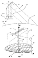
- Fig. 1 shows how, for example, by a satellite-supported SAR system 10 illuminates a strip-shaped area 12 on the earth's surface 14.
- the SAR system 10 includes an array 16 of antenna elements 18. Associated with the antenna elements 18 is a reflector 20, which has a reflector surface 22, an optical axis 24 and a vertex 26.
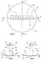
- FIG. 2 A perspective view and a top view of the reflector 20 with the antenna element array 16 is shown in FIG Fig. 2 in perspective and in Fig. 3 shown in plan view.
- the optical axis 24 extends in the Z-direction and forms the penetration line 28 of a X-axis extending first (X) plane 30 having a Y-axis extending second (Y) plane 32.
- the two planes 30 and 32 are at right angles to each other. It can be seen that the extension 34 of the one-dimensional antenna element array 16 (see the double arrow in the FIGS. 2 and 3 ) coincides with the X-axis extension.
- the peculiarity of the reflector 20 used according to the invention is based on the sectional views according to the FIGS. 4 and 5 to recognize. Thereafter, the parabolic shape, which is located as in the (X) plane 30 intersecting line 36 of Fig. 4 or as lying in the (Y) plane 32 section line 38 of Fig. 5 represents differently wide open.
- the reflector 20 in the (X) plane 30 defines a first (X) focal plane 40, which is located closer to the apex 26 of the reflector 20 than the second (Y) focal plane 42 located in the (Y-).
- Level 32 forms.
- Non-defocused parabolic reflectors are generated geometrically by rotating a parabola about an axis (eg Z-axis in FIG FIGS. 2 . 4 and 5 ).
- a characteristic of the reflector surface 22 is to bundle an anti-parallel to the z-axis incident plane wave in the so-called focal point, short focus.
- One possibility of defocusing is to construct the reflector with two focal points (focal planes 40, 42).
- F x and F y are the focal lengths, as in FIGS FIGS. 4 and 5 shown.
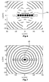
- the scattered field of an incident plane wave is no longer concentrated in a small environment around the focal point, but distributed over a larger area in one dimension (eg X-dimension), while the field in the orthogonal direction (Y-dimension ) remains focused (see Fig. 6 ).
- the underlying idea is to pivot the antenna beam in only one dimension. Therefore, the overlap between the individual antenna diagrams is only needed in this dimension. This is based on the field distributions in the illustrations in the Fign. 6 and 7 clear.
- FIG. 7 is the field distribution for an X-band reflector with conventional parabolic reflector surface, ie with only one focus.
- the squares represent the elements of the antenna element array, with the black square symbolizing the illuminated antenna element.
- a plurality of antenna elements 18 of the array 16 are illuminated simultaneously.
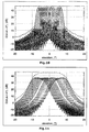
- FIG. 8 The corresponding antenna diagrams for a linear antenna element array with eleven elements are shown in FIG Fig. 8 represented as a section through the antenna pattern as a function of the elevation angle when using a conventional parabolic reflector.
- Each antenna diagram belongs to an antenna element of the array. Here it becomes obvious that the individual diagrams overlap only slightly. If one of the antenna elements fails, this area is no longer sufficiently illuminated.
- FIGS. 2 to 5 the antenna diagrams for the defocused reflector 20 according to FIGS FIGS. 2 to 5 shown.
- Each individual characteristic has a lower profit; however, increased gain can be generated digitally by beamforming (see the dashed curve in FIG Fig. 9 ).
- a device 44 for digital beam shaping is provided. The advantage of this antenna concept after the FIGS.
- FIGS. 10 and 11 clarified.
- Fig. 10 2 the antenna diagrams of a conventional parabolic reflector with a single focal plane are shown, wherein a central antenna element has failed and thus results in an indentation in the envelope (see dashed line).
- Fig. 11 shows that the failure of the central antenna element when using the reflector according to the invention does not appreciably affect the superposition (dashed line) of the antenna diagrams, namely because due to the targeted defocusing the antenna elements adjacent to the failed antenna element receive radiation.
- the antenna concept according to the invention can in principle be used wherever high reliability is required for the overall system. This mainly concerns antenna systems that can not be serviced, such as antennas carried by satellites.
- the reflector concept described above can be a solution to the redundancy problem, by a specific defocusing indicate.
- the three-dimensional field distribution which results from the scattering of a plane wave with the reflector, was simulated in the area of the focal plane.
- a distribution of the electromagnetic field can be achieved over a larger area (see the area 46 in FIG Fig. 6 opposite the area 48 in Fig. 7 ).
- the electromagnetic Power is radiated over a wider angular range ( Fig. 9 ).
- adjacent elements of the antenna element array illuminate a more overlapping angular range. In case of failure of an element, this ensures that this angular range still remains "visible".
- the invention unfolds its full potential in conjunction with digital beamforming.
- defocusing of the reflector is generally avoided because of the associated loss of antenna gain.
- an attempt is made to optimize the antenna beam so that, for example, a continent is optimally illuminated.
- the task is therefore to optimize the antenna characteristics simultaneously for a whole continuum of directions. Consequently, each direction is lit with a low gain.
- the antenna lobe should only be optimized for one direction at a time. In the next time step, the signal comes from a different direction and a new antenna beam is calculated.
- the loss of gain of a single antenna element for use in the field of synthetic aperture radars poses no problem because for each direction a high gain antenna lobe is digitally synthesized.
- Characteristic of the novelty of the invention is the geometric shape of the reflector, which differs from the common reflector shapes.
Landscapes
- Physics & Mathematics (AREA)
- Electromagnetism (AREA)
- Aerials With Secondary Devices (AREA)
- Variable-Direction Aerials And Aerial Arrays (AREA)
Description
- Zukünftige satelliten-gestützte Radarsysteme mit Apertur-Synthese sollen auf digitale Strahlformungstechniken zurück greifen. Hierbei werden Teile der analogen Empfangshardware durch digitale Komponenten ersetzt, was die Flexibilität solcher Systeme erhöht. Ziel ist es Radarbilder mit einem großen Aufnahmebereich (d.h. einer großen Streifenbreite) und gleichzeitig hoher Auflösung zu gewinnen. Aufgrund der begrenzten Sendeleistung werden Antennen mit großer Aperturfläche benötigt, die in der Lage sind, die Antennenkeule über einen großen Winkelbereich elektronisch zu steuern. Als innovatives Konzept erweisen sich parabolische Reflektorantennen in Kombination mit insbesondere digitalen Speise-Arrays. Die Anzahl der Antennenelemente und die Größe des Speise-Arrays richten sich nach der Streifenbreite, bzw. nach der Auflösung, die erzielt werden soll. Die Elemente werden dabei in der fokalen Ebene des Reflektors platziert. Ein solches SAR-System ist z.B. in
US 6 175 326 B1 oderUS-A-2007/0194977 beschrieben. - Eine inhärente Problematik solcher Antennen-Konzepte ist, dass jedes Antennenelement des Speise-Arrays nur einen kleinen Winkelbereich "sieht" (beleuchtet). Da sich die "Sichtbereiche" der einzelnen Antennenelemente des Speise-Arrays kaum überlappen, ergibt sich im Falle eines Speise-Element-Ausfalls ein "blinder" Bereich.
- Reflektorantennen werden typischerweise in den Bauformen als Paraboloid, als parabolischer Zylinder oder als Winkelreflektor realisiert. Den Stand der Technik repräsentiert beispielsweise das satelliten-basierte Radarsystem SAR-Lupe. Hier werden parabolische Reflektorantennen mit nur einer Speise-Antenne im Fokus oder mehreren Speiseantennen in der Fokalebene (
US 6 175 326 B1 ) verwendet. Die Schwenkung der Antennen-Keule erfolgt mechanisch. Ein anderer Anwendungsbereich ist die Signalübertragung mittels Kommunikationssatelliten mit Reflektorantennen. - Parabolische Reflektorantennen mit fokussiertem Speise-Array, d.h. das Speise- Array befindet sich in der fokalen Ebene, sind bei einem Ausfall eines Speise- Array Elements "blind" in der jeweiligen Richtung. Diese inhärente Problematik kann nur durch redundante Auslegung des Speise-Arrays umgangen werden. Diese Option stellt für Satelliten-Radarsysteme eine starke Kostenerhöhung dar. Zudem produziert die redundante Elektronik Verluste, zum Beispiel durch zusätzlich benötigte Schalter. Desweiteren erhöht sich die Gesamtmasse des Radar Instruments.
- Eine weitere Möglichkeit nach dem aktuellen Stand der Technik ist der Einsatz von planaren Array-Antennen (
EP-B-1 241 487 ), und zwar unter anderem auch mit digitaler Strahlformung, wie es beschrieben ist inUS-A-5,059,966 und PATYUCHENKO, A.; et al.: Optimization Aspects of the Reflector Antenna for the Digital Beam-Forming SAR System. In: 8th European Conference on Synthetic Aperture Radar (EUSAR), 2010, S. 954-957. Nachteilig sind hier die große Masse der Antenne und daraus resultierend hohe Kosten für Bau und Transport des Satelliten ins All. -
US-A-5 202 700 beschreibt ein Bodenradar zur Luftraumüberwachung, mit dem sich Objekte (z. B. Flugzeuge) drei-dimensional detektieren lassen, wobei die Antenne des Bodenradars sehr niedrige Nebenkeulen hat. Dazu werden im Sendefall zwei breite Antennenkeulen mittels eines analogen Strahl-Schaltnetzwerks gebildet, wobei eine der beiden Keulen den obere Elevationswinkelbereich beleuchtet und die andere Keule den unteren Elevationswinkelbereich. Im Empfangsfall werden analog zehn stationäre Empfangskeulen gebildet, mit denen das Signalecho erfasst wird. Die Signale jeweils zweier benachbarter Keulen werden dabei hinsichtlich der Signalamplitude verglichen, um den Elevationswinkel und damit die Höhe des Flugobjekts zu schätzen. Der verwendete Reflektor besitzt dabei einen Bereich, der zweifach-parabolisch ist, sowie einen Bereich, der von dieser Form abweicht. Das analoge Speisearray ist von zylindrischer Form. - Aufgabe der Erfindung ist es, eine Reflektorantenne für ein Radar mit synthetischer Apertur (SAR-System) zu schaffen, das robust gegen Ausfälle von Antennenelementen oder anderen Hardware- bzw. schaltungstechnischen Komponenten des Speise-Arrays ist.
- Zur Lösung dieser Aufgabe wird mit der Erfindung ein Radar mit synthetischer Apertur vorgeschlagen, das versehen ist mit den Merkmalen des Anspruchs 1. In den Unteransprüchen sind einzelne Ausgestaltungen der Erfindung angegeben.
- Bei dem erfindungsgemäßen SAR-System wird als Reflektorantenne ein Reflektor eingesetzt, der eindimensional defokussiert ist und zwei längs der optischen Achse voneinander beabstandete Fokalebenen aufweist und dessen Reflektorfläche daher von der idealen rotationssymmetrischen parabolischen Form abweicht, auf der die Reflektorantennen in den oben genannten Referenzen basieren. Dabei entsteht die erfindungsgemäße Reflektorfläche durch Rotation einer Parabel um eine Achse (nämlich die optische Achse des Reflektors), wobei jedoch die Öffnung der Parabel in Abhängigkeit von dem Rotationswinkel periodisch verändert wird. Hierdurch entsteht ein Reflektor, dessen Parabellinien bei Betrachtung längs zweier rechtwinklig zueinander stehender Schnittebenen durch den Reflektor unterschiedlich weit geöffnet sind. Hierdurch weist der Reflektor - bei Betrachtung in den beiden Schnittebenen - unterschiedlich weit vom Scheitelpunkt entfernt liegende Fokalebenen auf. Die nebeneinander angeordneten Antennenelemente sind dabei längs einer Linie angeordnet, die in Höhe einer der beiden Fokalebenen verläuft. Damit sind die Antennenelemente für reflektierte Strahlung innerhalb derjenigen Ebene, in der sich die Anordnungslinie der Antennenelemente erstreckt, gewünschtermaßen defokussiert, während sie in der dazu rechtwinklig verlaufenden anderen Ebene weiterhin stark fokussiert sind.
- In vorteilhafter Weiterbildung der Erfindung ist ferner vorgesehen, dass die Schnittlinie der Reflektorfläche mit der ersten (Fokal-)Ebene eine erste Parabel beschreibt, die weniger weit geöffnet ist als eine zweite Parabel, die die Schnittlinie der Reflektorfläche mit der zweiten (Fokal-)Ebene beschreibt.
- Ferner kann mit Vorteil vorgesehen sein, dass die Antennenelemente zum Belichten eines streifenförmigen Belichtungsbereichs auf einer Oberfläche vorgesehen sind, wobei die Längserstreckung des Belichtungsbereichs parallel zur Aufeinanderfolge der nebeneinander angeordneten Antennenelemente gerichtet ist bzw. die Längserstreckung des streifenförmigen Belichtungsbereichs und die Aufeinanderfolge der nebeneinander angeordneten Antennenelemente innerhalb einer gemeinsamen, rechtwinklig zum streifenförmigen Belichtungsbereich verlaufenden Ebene angeordnet sind.
- Die Erfindung betrifft also ein SAR-System mit einem neuen Typ von Reflektorantenne, mit der es erstmalig möglich ist, die Vorzüge planarer Gruppenantennen, nämlich die Erhaltung der Funktionsfähigkeit der Antenne bei Ausfall eines Antennenelements, mit den Vorteilen von Reflektorantennen, nämlich der Bereitstellung großer Aperturflächen, zu kombinieren. Solche Reflektorantennen können mit Hilfe leichter Materialien realisiert werden und eignen sich damit insbesondere für satellitengetragene SAR-Systeme. Sollten allerdings bei Reflektorantennen das ein oder andere Speise-Array-Element ausfallen, so ist dies nachteilig, da der von der Reflektorantenne ausgeleuchtete Bereich Schattenbereiche, in denen keine Beleuchtung stattfindet, aufweist. Planare Gruppenantennen hingegen sind insoweit vorteilhaft, als dass der Ausfall eines einzelnen Antennenelements ebengerade keine nichtbeleuchteten Bereiche zur Folge hat. Wenn man nun beide Antennensysteme miteinander kombinieren kann, wie es nach der Erfindung vorgeschlagen wird, können die jeweiligen Vorzüge beider Antennensysteme übernommen werden. Hierdurch können die Kosten von beispielsweise satellitengetragenen SAR-Systemen signifikant gesenkt werden, da teure redundante Empfangselektronik vermieden werden kann.
- Anwendungsbereiche der erfindungsgemäßen Antenne sind beispielsweise Erdbeobachtungsmissionen mit SAR-Systemen bzw. alle Arten von Radarsystemen und Kommunikationssystemen, die nicht gewartet werden können. Dazu zählen in erster Linie satellitengetragene Systeme. Weitere Anwendungsgebiete sind darüber hinaus militärische und zivile Bodenradare. Bodenradarsysteme können beispielsweise für die Luftraumüberwachung und für die Wetterbeobachtung eingesetzt werden.
- Die Erfindung wird nachfolgend anhand eines Ausführungsbeispiels und unter Bezugnahme auf die Zeichnung näher erläutert. Im Einzelnen zeigen dabei:
- Fig. 1
- schematisch ein beispielsweise satelliten-gestütztes SAR-System zur Beleuchtung eines streifenförmigen Bereichs auf beispielsweise der Erdoberfläche,
- Fig. 2
- eine perspektivische Darstellung des Reflektors mit Antennenelement (Speise-)Array,
- Fig. 3
- eine Draufsicht auf den Reflektor mit vor diesem angeordneten (Spei-se-)Array,
- Fig. 4
- eine Schnittansicht durch den Reflektor mit dem (Speise-)Array entlang der (X-)Ebene IV-IV der
Fig. 3 , - Fig. 5
- eine Schnittansicht durch den Reflektor mit dem (Speise-)Array entlang der (Y-)Ebene V-V der
Fig. 3 , - Fig. 6
- die Feldverteilung in der Ebene durch den oberen fokalen Punkt gemäß
Fig. 5 für den Reflektor mit zwei Foki, - Fig. 7
- die Feldverteilung in der (einzigen) fokalen Ebene für einen konventionellen parabolischen Reflektor mit lediglich einem Fokus,
- Fig. 8
- eine Schnittgrafik des Antennendiagramms als Funktion des Elevationswinkels für einen konventionellen parabolischen Reflektor mit lediglich einem einzigen Fokus und - in diesem Beispiel - elf Antennenelementen, wobei jedes Antennendiagramm zu einem anderen Antennenelement gehört,
- Fig. 9
- eine Schnittgrafik des Antennendiagramms als Funktion des Elevationswinkels für einen Reflektor mit zwei Foki gemäß den
Fign. 2 bis 5 und beispielhaft wiederum elf Antennenelementen, - Fig. 10
- eine Schnittgrafik des Antennendiagramms als Funktion des Elevationswinkels für einen konventionellen parabolischen Reflektor mit lediglich einem Foki und wiederum beispielhaft elf Antennenelementen, wobei ein mittleres Antennenelement ausgefallen ist, und
- Fig. 11
- eine Schnittgrafik des Antennendiagramms als Funktion des Elevationswinkels für einen Reflektor mit zwei Foki gemäß den
Fign. 2 bis 5 und beispielhaft wiederum elf Antennenelementen, wobei ein mittleres Antennenelement ausgefallen ist. -
Fig. 1 zeigt, wie beispielsweise durch ein von einem Satelliten getragenes SAR-System 10 einen streifenförmigen Bereich 12 auf der Erdoberfläche 14 ausleuchtet. Das SAR-System 10 weist ein Array 16 aus Antennenelementen 18 auf. Den Antennenelementen 18 zugeordnet ist ein Reflektor 20, der eine Reflektorfläche 22, eine optische Achse 24 und einen Scheitelpunkt 26 aufweist. - Eine perspektivische Ansicht sowie eine Draufsicht des Reflektors 20 mit dem Antennenelement-Array 16 ist in
Fig. 2 perspektivisch und inFig. 3 in Draufsicht gezeigt. Unter Zugrundelegung des kartesischen Koordinatenkreuzes gemäßFig. 2 erstreckt sich die optische Achse 24 in Z-Richtung und bildet die Durchdringungslinie 28 einer sich in X-Achsenrichtung erstreckenden ersten (X-)Ebene 30 mit einer sich in Y-Achsenrichtung erstreckenden zweiten (Y-)Ebene 32. Die beiden Ebenen 30 und 32 stehen rechtwinklig zueinander. Zu erkennen ist, dass die Erstreckung 34 des eindimensionalen Antennenelement-Array 16 (siehe den Doppelpfeil in denFign. 2 und3 ) mit der X-Achsenerstreckung zusammenfällt. - Die Besonderheit des erfindungsgemäß verwendeten Reflektors 20 ist anhand der Schnittdarstellungen gemäß den
Fign. 4 und 5 zu erkennen. Danach ist die Parabelform, die sich als in der (X-)Ebene 30 liegende Schnittlinie 36 derFig. 4 bzw. als in der (Y-)Ebene 32 liegende Schnittlinie 38 derFig. 5 darstellt, unterschiedlich weit geöffnet. Damit definiert der Reflektor 20 in der (X-)Ebene 30 eine erste (X-) Fokalebene 40, die näher zum Scheitelpunkt 26 des Reflektors 20 angeordnet ist als die zweite (Y-)Fokalebene 42, die sich in der (Y-)Ebene 32 bildet. - Im Folgenden sollen anhand des Ausführungsbeispiels die Vorteile des erfindungsgemäßen defokussierten Reflektors 20 dargestellt werden.
- Nicht defokussierte parabolische Reflektoren werden geometrisch dadurch erzeugt, dass man eine Parabel um eine Achse rotiert (z.B. Z-Achse in
Fign. 2 ,4 und 5 ). Eine Eigenschaft der Reflektorfläche 22 besteht darin, eine anti-parallel zur z-Achse einfallende ebene Welle im sogenannten fokalen Punkt, kurz Fokus, zu bündeln. Eine Möglichkeit der Defokussierung besteht darin, den Reflektor mit zwei fokalen Punkten (Fokalebenen 40,42) zu konstruieren. Der geometrische Ort der Reflektorfläche 22 kann in kartesischen Koordinaten mit der Gleichung
Fign. 4 und 5 dargestellt. - Platziert man das Antennenelement-Array in einem der beiden Foki (z.B. im oberen Fokus (siehe
Fig. 5 )), wird das gestreute Feld einer einfallenden ebene Welle nicht mehr in einer kleinen Umgebung um den fokalen Punkt konzentriert, sondern in einer Dimension (z.B. X-Dimension) über einen größeren Bereich verteilt, während das Feld in der orthogonalen Richtung (Y-Dimension) fokussiert bleibt (sieheFig. 6 ). Dies ist in denFign. 6 und 7 durch die schwarzen Quadrate angedeutet, die die jeweilige Rückstrahlung empfangenden Antennenelemente 18 zeigen. Die zu Grunde liegende Idee besteht darin, den Antennen-Strahl nur in einer Dimension zu schwenken. Daher wird der Überlapp zwischen den einzelnen Antennendiagrammen auch nur in dieser Dimension benötigt. Dies wird anhand der Feldverteilungen in den Abbildungen in denFign 6 und 7 deutlich. InFig. 7 ist die Feldverteilung für einen X-Band Reflektor mit konventioneller parabolischer Reflektorfläche, d.h. mit nur einem Fokus, dargestellt. Der Reflektor hat einen Durchmesser von 7m mit einer fokalen Länge von Fx = Fy = 5m. Die dargestellte Feldebene ist die fokale Ebene z = 5m. Die Quadrate repräsentieren die Elemente des Antennenelement-Arrays, wobei das schwarze Quadrat das beleuchtete Antennenelement symbolisiert. InFig. 6 ist die Feldverteilung für einen Reflektor mit demselben Durchmesser aber mit zwei Foki (Fx = 4.9m und Fy = 5.1m) dargestellt. Die Feldebene befindet sich im oberen fokalen Punkt bei z = 5.1m. Hier wird deutlich, dass mehrere Antennenelemente 18 des Arrays 16 gleichzeitig beleuchtet werden. - Die dazugehörigen Antennendiagramme für ein lineares Antennenelement-Array mit elf Elementen sind in
Fig. 8 dargestellt, und zwar als Schnitt durch das Antennendiagramm als Funktion des Elevationswinkels bei Verwendung eines konventionellen parabolischen Reflektor. Jedes Antennendiagramm gehört zu einem Antennenelement des Arrays. Hier wird offensichtlich, dass sich die einzelnen Diagramme nur schwach überlappen. Fällt eines der Antennenelemente aus, wird dieser Bereich nicht mehr ausreichend beleuchtet. InFig. 8 sind die Antennendiagramme für den defokussierten Reflektor 20 gemäß denFign. 2 bis 5 dargestellt. Jede Einzelcharakteristik hat zwar einen geringeren Gewinn; ein erhöhter Gewinn kann jedoch durch Strahlformung digital erzeugt werden (siehe die gestrichelte Kurve inFig. 9 ). Hierzu ist eine Vorrichtung 44 zur digitalen Strahlformung vorgesehen. Der Vorteil dieses Antennen-Konzepts nach denFign. 2 bis 5 besteht darin, dass bei einem Ausfall eines Antennenelements der betroffene Winkelbereich immer noch ausreichend durch Nachbarelemente beleuchtet wird. Dies ist anhand derFign. 10 und 11 verdeutlicht. InFig. 10 sind die Antennendiagramme eines konventionellen parabolischen Reflektors mit einer einzigen Fokalebene gezeigt, wobei ein mittleres Antennenelement ausgefallen ist und sich damit in der Einhüllenden (siehe gestrichelte Linie) eine Einbuchtung ergibt.Fig. 11 zeigt, dass sich der Ausfall des mittleren Antennenelements bei Verwendung des erfindungsgemäßen Reflektors nicht nennenswert auf die Überlagerung (gestrichelte Linie) der Antennendiagramme auswirkt, da nämlich auf Grund der gezielten Defokussierung die zum ausgefallenen Antennenelement benachbarten Antennenelemente Strahlung empfangen. - Das erfindungsgemäße Antennen-Konzept kann im Prinzip überall dort eingesetzt werden, wo eine hohe Zuverlässigkeit für das Gesamtsystem verlangt wird. Das betrifft vorwiegend Antennen-Systeme die nicht gewartet werden können, wie zum Beispiel von Satelliten getragenen Antennen.
- Mit dem zuvor beschriebenen Reflektorkonzept lässt sich eine Lösung des Redundanz-Problems, und zwar durch eine gezielte Defokussierung, angeben. Hierzu wurde die dreidimensionale Feldverteilung, die sich aus der Streuung einer ebenen Welle mit dem Reflektor ergibt, im Bereich der fokalen Ebene simuliert. Durch Variation der Reflektorform lässt sich eine Verteilung des elektromagnetischen Feldes über einen größeren Bereich erzielen (siehe den Bereich 46 in
Fig. 6 gegenüber dem Bereich 48 inFig. 7 ). Auf diese Weise wird sichergestellt, dass mehrere Elemente des Antennenelement-Arrays, angedeutet durch die schwarzen Quadrate inFig. 6 , einen Teil der Feldenergie aufnehmen. Umgekehrt kann man aus Reziprozitätsgründen daraus ableiten, dass die elektromagnetische Leistung über einen breiteren Winkelbereich abgestrahlt wird (Fig. 9 ). Dies hat zur Folge, dass benachbarte Elemente des Antennenelement-Arrays einen stärker überlappenden Winkelbereich beleuchten. Bei einem Ausfall eines Elements ist damit gewährleistet, dass dieser Winkelbereich immer noch "sichtbar" bleibt. - Die Erfindung entfaltet ihr volles Potential in Verbindung mit digitaler Strahlformung. Bei Anwendungen wie der satelliten-gestützten Kommunikation wird generell eine Defokussierung des Reflektors vermieden, weil damit ein Verlust an Antennengewinn einhergeht. Bei solchen Anwendungen wird versucht, den Antennenstrahl so zu optimieren, dass beispielsweise ein Kontinent optimal ausgeleuchtet wird. Die Aufgabe besteht also darin, die Antennencharakteristik gleichzeitig für ein ganzes Kontinuum an Richtungen zu optimieren. Folglich wird jede Richtung mit einem niedrigen Gewinn beleuchtet. Im Gegensatz dazu soll bei synthetischen Apertur Radaren die Antennenkeule zu einem Zeitpunkt nur für eine Richtung optimiert werden. Im nächsten Zeitschritt kommt das Signal aus einer anderen Richtung und es wird ein neuer Antennenstrahl berechnet. Insofern stellt der Verlust an Gewinn eines einzelnen Antennenelements für die Anwendung im Bereich synthetischer Apertur-Radare kein Problem dar, weil für jede Richtung eine Antennenkeule mit hohem Gewinn digital synthetisiert wird.
- Charakteristisch für die Neuheit der Erfindung ist die geometrische Form des Reflektors, die von den gängigen Reflektorformen abweicht.
-
- 10
- SAR-System
- 12
- Belichtungsbereich
- 14
- Erdoberfläche,
- 16
- Antennenelement-Array
- 18
- Antennenelemente
- 20
- Reflektor
- 22
- Reflektorfläche
- 24
- optische Achse
- 26
- Scheitelpunkt der Reflektorfläche
- 28
- Durchdringungslinie der (X-) und (Y-)Ebenen
- 30
- (X-)Ebene
- 32
- (Y-)Ebene
- 34
- Erstreckung der Aufeinanderfolge der Antennenelemente
- 36
- Schnittlinie des Reflektors mit der (X-)Ebene
- 38
- Schnittlinie des Reflektors mit der (Y-)Ebene
- 40
- (X-)Fokalebene
- 42
- (Y-)Fokalebene
- 44
- Vorrichtung zur digitalen Strahlformung
- 46
- Bereich der Verteilung des elektromagnetischen Feldes
- 48
- Bereich der Verteilung des elektromagnetischen Feldes
Claims (3)
- Radar mit synthetischer Apertur, mit- einem Reflektor (20) mit einer Reflektorfläche (22) und einem Scheitelpunkt (26) sowie einer sich von diesem aus erstreckenden optischen Achse (24) und- mehreren nebeneinander in einer Reihe angeordneten Antennenelementen (18) zum Aussenden von Radar-Sendesignalen und zum Empfangen von durch Reflektion an einer Oberfläche (14) entstandenen Radar-Empfangssignalen,dadurch gekennzeichnet,- dass der Reflektor (20) als eindimensional defokussierter Reflektor (20) mit zwei Fokalebenen (40,42) ausgebildet ist,- dass die optische Achse (24) mit der Durchdringungslinie (28) zweier zueinander rechtwinkliger, gedachter Ebenen, nämlich einer ersten (X-)Ebene (30) und einer zweiten (Y-)Ebene (32) zusammenfällt,- dass der Reflektor (20) in der ersten (X-)Ebene (30) eine zu dieser sowie zur optischen Achse (24) rechtwinklig verlaufende erste (X-) Fokalebene (40) aufweist,- dass der Reflektor (20) in der zweiten (Y-)Ebene (32) eine zu dieser sowie zur optischen Achse rechtwinklig verlaufende zweite (Y-) Fokalebene (42) aufweist,- dass die zweite (Y-)Fokalebene (42) einen größeren Abstand vom Scheitelpunkt aufweist als die erste (X-)Fokalebene (40),- dass die Antennenelemente (18) bei Betrachtung der ersten (X-)Ebene (30) des Reflektors (20) längs einer in der ersten (X-)Ebene (30) verlaufenden (X-)Linie (34) nebeneinander angeordnet sind,- wobei die (X-)Linie (34) in Höhe der zweiten (Y-)Fokalebene (42) verläuft, und- dass eine Vorrichtung (44) zur digitalen Strahlformung vorgesehen ist.
- Radar mit synthetischer Apertur nach Anspruch 1, dadurch gekennzeichnet, dass die Schnittlinie (36) der Reflektorfläche (22) mit der ersten (X-) Ebene (30) eine erste (X-) Parabel beschreibt, die weniger weit geöffnet ist als eine zweite (Y-) Parabel, die die Schnittlinie (38) der Reflektorfläche (22) mit der zweiten (Y-)Ebene (32) beschreibt.
- Radar mit synthetischer Apertur nach Anspruch 1 oder 2, dadurch gekennzeichnet, dass die Antennenelemente (18) zum Beleuchten eines streifenförmigen Beleuchtungsbereichs (12) auf einer Oberfläche (14) vorgesehen sind, wobei die Längserstreckung des Beleuchtungsbereichs (12) parallel zur Aufeinanderfolge der nebeneinander angeordneten Antennenelemente (18) gerichtet ist bzw. die Längserstreckung des streifenförmigen Beleuchtungsbereichs (12) und die Aufeinanderfolge der nebeneinander angeordneten Antennenelemente (18) innerhalb einer gemeinsamen, rechtwinklig zum streifenförmigen Beleuchtungsbereich (12) verlaufenden Ebene angeordnet sind.
Applications Claiming Priority (2)
| Application Number | Priority Date | Filing Date | Title |
|---|---|---|---|
| DE102011108159 | 2011-07-20 | ||
| PCT/EP2012/064000 WO2013011023A1 (de) | 2011-07-20 | 2012-07-17 | Reflektorantenne für ein radar mit synthetischer apertur |
Publications (2)
| Publication Number | Publication Date |
|---|---|
| EP2735055A1 EP2735055A1 (de) | 2014-05-28 |
| EP2735055B1 true EP2735055B1 (de) | 2016-02-10 |
Family
ID=46579010
Family Applications (1)
| Application Number | Title | Priority Date | Filing Date |
|---|---|---|---|
| EP12738439.4A Active EP2735055B1 (de) | 2011-07-20 | 2012-07-17 | Reflektorantenne für ein radar mit synthetischer apertur |
Country Status (3)
| Country | Link |
|---|---|
| US (1) | US9531081B2 (de) |
| EP (1) | EP2735055B1 (de) |
| WO (1) | WO2013011023A1 (de) |
Cited By (1)
| Publication number | Priority date | Publication date | Assignee | Title |
|---|---|---|---|---|
| CN106571511A (zh) * | 2016-11-15 | 2017-04-19 | 长春理工大学 | 轻型可折叠微波和激光混合薄膜通信天线 |
Families Citing this family (14)
| Publication number | Priority date | Publication date | Assignee | Title |
|---|---|---|---|---|
| CN103094685B (zh) * | 2013-01-25 | 2014-12-03 | 西安电子科技大学 | 基于轴向偏焦的大型天线罩电性能补偿方法 |
| WO2016153914A1 (en) | 2015-03-25 | 2016-09-29 | King Abdulaziz City Of Science And Technology | Apparatus and methods for synthetic aperture radar with digital beamforming |
| US10199711B2 (en) * | 2015-05-13 | 2019-02-05 | The Arizona Board Of Regents On Behalf Of The University Of Arizona | Deployable reflector antenna |
| WO2017044168A2 (en) | 2015-06-16 | 2017-03-16 | King Abdulaziz City Of Science And Technology | Efficient planar phased array antenna assembly |
| EP3380864A4 (de) | 2015-11-25 | 2019-07-03 | Urthecast Corp. | Radarbildgebungsvorrichtung mit synthetischer apertur und verfahren |
| US10158170B2 (en) * | 2016-01-25 | 2018-12-18 | International Business Machines Corporation | Two-dimensional scanning cylindrical reflector |
| IL243863B (en) * | 2016-01-28 | 2021-01-31 | Retter Alon | Array of scanner antennas with Zen and multifocal reflector |
| WO2018148543A1 (en) * | 2017-02-10 | 2018-08-16 | Porter Carl Edmund | Apparatus and method for generating and capturing a transmission wave and apparatus and method for transmitting and receiving digital information |
| CA3064586A1 (en) | 2017-05-23 | 2018-11-29 | King Abdullah City Of Science And Technology | Synthetic aperture radar imaging apparatus and methods for moving targets |
| EP3631504B8 (de) | 2017-05-23 | 2023-08-16 | Spacealpha Insights Corp. | Radarbildgebungsvorrichtung mit synthetischer apertur und verfahren |
| US11525910B2 (en) | 2017-11-22 | 2022-12-13 | Spacealpha Insights Corp. | Synthetic aperture radar apparatus and methods |
| US11688950B2 (en) * | 2020-08-10 | 2023-06-27 | Lockheed Martin Corporation | Multisegment array-fed ring-focus reflector antenna for wide-angle scanning |
| TWI774237B (zh) * | 2021-02-09 | 2022-08-11 | 國立臺灣大學 | 具有碟型反射面的天線量測系統 |
| CN113126087B (zh) * | 2021-03-10 | 2021-11-09 | 中国科学院国家空间科学中心 | 一种星载干涉成像高度计天线 |
Family Cites Families (10)
| Publication number | Priority date | Publication date | Assignee | Title |
|---|---|---|---|---|
| US5202700A (en) * | 1988-11-03 | 1993-04-13 | Westinghouse Electric Corp. | Array fed reflector antenna for transmitting & receiving multiple beams |
| JPH0727021B2 (ja) | 1989-02-10 | 1995-03-29 | 三菱電機株式会社 | 合成開口レーダ装置 |
| US5175562A (en) | 1989-06-23 | 1992-12-29 | Northeastern University | High aperture-efficient, wide-angle scanning offset reflector antenna |
| US6175326B1 (en) | 1998-06-29 | 2001-01-16 | The Regents Of The University Of California | Moving receive beam method and apparatus for synthetic aperture radar |
| FR2793073B1 (fr) | 1999-04-30 | 2003-04-11 | France Telecom | Antenne a reflecteur continu pour reception multiple de faisceaux de satellite |
| AU2001251381A1 (en) * | 2000-04-07 | 2001-10-30 | Gilat Satellite Networks | Multi-feed reflector antenna |
| ES2256102T3 (es) | 2001-03-15 | 2006-07-16 | Eads Astrium Gmbh | Sistema de radar de apertura sintetica de exploracion lateral. |
| FR2868847B1 (fr) | 2004-04-13 | 2008-12-26 | Eads Astrium Sas Soc Par Actio | Dispositif de detection comprenant un miroir parabolique, et utilisation d'un tel dispositif a bord d'un engin de survol |
| US8354956B2 (en) * | 2006-01-13 | 2013-01-15 | Lockheed Martin Corporation | Space segment payload architecture for mobile satellite services (MSS) systems |
| US8315557B1 (en) * | 2009-12-31 | 2012-11-20 | Lockheed Martin Corporation | Common aperture antenna for multiple contoured beams and multiple spot beams |
-
2012
- 2012-07-17 US US14/233,816 patent/US9531081B2/en active Active
- 2012-07-17 EP EP12738439.4A patent/EP2735055B1/de active Active
- 2012-07-17 WO PCT/EP2012/064000 patent/WO2013011023A1/de active Application Filing
Cited By (2)
| Publication number | Priority date | Publication date | Assignee | Title |
|---|---|---|---|---|
| CN106571511A (zh) * | 2016-11-15 | 2017-04-19 | 长春理工大学 | 轻型可折叠微波和激光混合薄膜通信天线 |
| CN106571511B (zh) * | 2016-11-15 | 2019-05-03 | 长春理工大学 | 轻型可折叠微波和激光混合薄膜通信天线 |
Also Published As
| Publication number | Publication date |
|---|---|
| EP2735055A1 (de) | 2014-05-28 |
| US9531081B2 (en) | 2016-12-27 |
| WO2013011023A1 (de) | 2013-01-24 |
| US20140225798A1 (en) | 2014-08-14 |
Similar Documents
| Publication | Publication Date | Title |
|---|---|---|
| EP2735055B1 (de) | Reflektorantenne für ein radar mit synthetischer apertur | |
| DE2248325C2 (de) | Antenne zum Senden oder Empfangen mit schwenkbarem Strahlenbündel | |
| DE102013105809B4 (de) | Multifunktionale Radaranordnung | |
| EP2965382B1 (de) | Antennenanordnung mit veränderlicher richtcharakteristik | |
| DE102007036262A1 (de) | Radarsensor für Kraftfahrzeuge | |
| EP2862235B1 (de) | Antennenanordnung und verfahren | |
| DE2610304A1 (de) | Dynamisch fokussierte antennenanordnung | |
| EP2449406B1 (de) | Radarsensor für kraftfahrzeuge | |
| EP3701280B1 (de) | Radarsensor mit mehreren hauptstrahlrichtungen | |
| DE2306407C3 (de) | Antennensystem hoher Winkelauflösung für Radargeräte mit getrennten Sende- und Empfangsantennen | |
| EP0915349B1 (de) | Radarsystem zum Abbilden von Sektoren | |
| DE102018008381B4 (de) | HPEM-Quelle, Fahrzeug und Verfahren | |
| DE2415020A1 (de) | Antennensystem | |
| DE69212378T2 (de) | Antenne mit geformter Strahlungskeule und hohem Gewinn | |
| DE2632615C3 (de) | Satelliten-Nachrichtenübertragungssystem | |
| DE19844239C1 (de) | Verfahren zur genauen Winkelbestimmung von Zielen mittels eines Mehrfachantennen-Radarsystems | |
| DE69430556T2 (de) | Aktive Antenne mit elektronischem Absuchen in Azimut und Elevation, insbesondere für Mikrowellen-Abbildung mittels Satellit | |
| DE102014106060A1 (de) | Antennenanordnung | |
| EP1968158B1 (de) | Systemintegriertes Bodenstationsantennen-Kalibrierungssystem inkl. Phasenabgleich für automatisches Tracking (Autotracking) | |
| DE19845868A1 (de) | Doppelfokusplanarantenne | |
| DE2821699C2 (de) | Antenne mit wenigstens zwei voneinander unabhängigen Strahlungquellen | |
| DE2921856A1 (de) | Richtantenne | |
| DE60120909T2 (de) | Doppeltreflektor-Antenne mit Ablenker | |
| EP2662928B1 (de) | Antennenvorrichtung und Verfahren zum elektronischen Schwenken eines Radarstrahls | |
| DE102018111123A1 (de) | Antennen-Array mit Sende- und Empfangsantennenelementen und Verfahren zum Betreiben eines Antennen-Arrays |
Legal Events
| Date | Code | Title | Description |
|---|---|---|---|
| PUAI | Public reference made under article 153(3) epc to a published international application that has entered the european phase |
Free format text: ORIGINAL CODE: 0009012 |
|
| 17P | Request for examination filed |
Effective date: 20140129 |
|
| AK | Designated contracting states |
Kind code of ref document: A1 Designated state(s): AL AT BE BG CH CY CZ DE DK EE ES FI FR GB GR HR HU IE IS IT LI LT LU LV MC MK MT NL NO PL PT RO RS SE SI SK SM TR |
|
| DAX | Request for extension of the european patent (deleted) | ||
| GRAP | Despatch of communication of intention to grant a patent |
Free format text: ORIGINAL CODE: EPIDOSNIGR1 |
|
| RIC1 | Information provided on ipc code assigned before grant |
Ipc: G01S 13/90 20060101ALI20150723BHEP Ipc: H01Q 3/26 20060101AFI20150723BHEP Ipc: H01Q 5/45 20150101ALI20150723BHEP Ipc: H01Q 19/17 20060101ALI20150723BHEP Ipc: H01Q 15/16 20060101ALI20150723BHEP |
|
| INTG | Intention to grant announced |
Effective date: 20150805 |
|
| GRAS | Grant fee paid |
Free format text: ORIGINAL CODE: EPIDOSNIGR3 |
|
| GRAA | (expected) grant |
Free format text: ORIGINAL CODE: 0009210 |
|
| AK | Designated contracting states |
Kind code of ref document: B1 Designated state(s): AL AT BE BG CH CY CZ DE DK EE ES FI FR GB GR HR HU IE IS IT LI LT LU LV MC MK MT NL NO PL PT RO RS SE SI SK SM TR |
|
| REG | Reference to a national code |
Ref country code: GB Ref legal event code: FG4D Free format text: NOT ENGLISH |
|
| REG | Reference to a national code |
Ref country code: AT Ref legal event code: REF Ref document number: 775048 Country of ref document: AT Kind code of ref document: T Effective date: 20160215 Ref country code: CH Ref legal event code: EP |
|
| REG | Reference to a national code |
Ref country code: IE Ref legal event code: FG4D Free format text: LANGUAGE OF EP DOCUMENT: GERMAN |
|
| REG | Reference to a national code |
Ref country code: DE Ref legal event code: R096 Ref document number: 502012005984 Country of ref document: DE |
|
| REG | Reference to a national code |
Ref country code: LT Ref legal event code: MG4D |
|
| REG | Reference to a national code |
Ref country code: NL Ref legal event code: MP Effective date: 20160210 |
|
| REG | Reference to a national code |
Ref country code: FR Ref legal event code: PLFP Year of fee payment: 5 |
|
| PG25 | Lapsed in a contracting state [announced via postgrant information from national office to epo] |
Ref country code: NO Free format text: LAPSE BECAUSE OF FAILURE TO SUBMIT A TRANSLATION OF THE DESCRIPTION OR TO PAY THE FEE WITHIN THE PRESCRIBED TIME-LIMIT Effective date: 20160510 Ref country code: ES Free format text: LAPSE BECAUSE OF FAILURE TO SUBMIT A TRANSLATION OF THE DESCRIPTION OR TO PAY THE FEE WITHIN THE PRESCRIBED TIME-LIMIT Effective date: 20160210 Ref country code: FI Free format text: LAPSE BECAUSE OF FAILURE TO SUBMIT A TRANSLATION OF THE DESCRIPTION OR TO PAY THE FEE WITHIN THE PRESCRIBED TIME-LIMIT Effective date: 20160210 Ref country code: HR Free format text: LAPSE BECAUSE OF FAILURE TO SUBMIT A TRANSLATION OF THE DESCRIPTION OR TO PAY THE FEE WITHIN THE PRESCRIBED TIME-LIMIT Effective date: 20160210 Ref country code: GR Free format text: LAPSE BECAUSE OF FAILURE TO SUBMIT A TRANSLATION OF THE DESCRIPTION OR TO PAY THE FEE WITHIN THE PRESCRIBED TIME-LIMIT Effective date: 20160511 |
|
| PG25 | Lapsed in a contracting state [announced via postgrant information from national office to epo] |
Ref country code: LV Free format text: LAPSE BECAUSE OF FAILURE TO SUBMIT A TRANSLATION OF THE DESCRIPTION OR TO PAY THE FEE WITHIN THE PRESCRIBED TIME-LIMIT Effective date: 20160210 Ref country code: RS Free format text: LAPSE BECAUSE OF FAILURE TO SUBMIT A TRANSLATION OF THE DESCRIPTION OR TO PAY THE FEE WITHIN THE PRESCRIBED TIME-LIMIT Effective date: 20160210 Ref country code: NL Free format text: LAPSE BECAUSE OF FAILURE TO SUBMIT A TRANSLATION OF THE DESCRIPTION OR TO PAY THE FEE WITHIN THE PRESCRIBED TIME-LIMIT Effective date: 20160210 Ref country code: LT Free format text: LAPSE BECAUSE OF FAILURE TO SUBMIT A TRANSLATION OF THE DESCRIPTION OR TO PAY THE FEE WITHIN THE PRESCRIBED TIME-LIMIT Effective date: 20160210 Ref country code: SE Free format text: LAPSE BECAUSE OF FAILURE TO SUBMIT A TRANSLATION OF THE DESCRIPTION OR TO PAY THE FEE WITHIN THE PRESCRIBED TIME-LIMIT Effective date: 20160210 Ref country code: IS Free format text: LAPSE BECAUSE OF FAILURE TO SUBMIT A TRANSLATION OF THE DESCRIPTION OR TO PAY THE FEE WITHIN THE PRESCRIBED TIME-LIMIT Effective date: 20160610 Ref country code: PL Free format text: LAPSE BECAUSE OF FAILURE TO SUBMIT A TRANSLATION OF THE DESCRIPTION OR TO PAY THE FEE WITHIN THE PRESCRIBED TIME-LIMIT Effective date: 20160210 Ref country code: PT Free format text: LAPSE BECAUSE OF FAILURE TO SUBMIT A TRANSLATION OF THE DESCRIPTION OR TO PAY THE FEE WITHIN THE PRESCRIBED TIME-LIMIT Effective date: 20160613 |
|
| PG25 | Lapsed in a contracting state [announced via postgrant information from national office to epo] |
Ref country code: EE Free format text: LAPSE BECAUSE OF FAILURE TO SUBMIT A TRANSLATION OF THE DESCRIPTION OR TO PAY THE FEE WITHIN THE PRESCRIBED TIME-LIMIT Effective date: 20160210 Ref country code: DK Free format text: LAPSE BECAUSE OF FAILURE TO SUBMIT A TRANSLATION OF THE DESCRIPTION OR TO PAY THE FEE WITHIN THE PRESCRIBED TIME-LIMIT Effective date: 20160210 |
|
| REG | Reference to a national code |
Ref country code: DE Ref legal event code: R097 Ref document number: 502012005984 Country of ref document: DE |
|
| PG25 | Lapsed in a contracting state [announced via postgrant information from national office to epo] |
Ref country code: CZ Free format text: LAPSE BECAUSE OF FAILURE TO SUBMIT A TRANSLATION OF THE DESCRIPTION OR TO PAY THE FEE WITHIN THE PRESCRIBED TIME-LIMIT Effective date: 20160210 Ref country code: SM Free format text: LAPSE BECAUSE OF FAILURE TO SUBMIT A TRANSLATION OF THE DESCRIPTION OR TO PAY THE FEE WITHIN THE PRESCRIBED TIME-LIMIT Effective date: 20160210 Ref country code: SK Free format text: LAPSE BECAUSE OF FAILURE TO SUBMIT A TRANSLATION OF THE DESCRIPTION OR TO PAY THE FEE WITHIN THE PRESCRIBED TIME-LIMIT Effective date: 20160210 Ref country code: RO Free format text: LAPSE BECAUSE OF FAILURE TO SUBMIT A TRANSLATION OF THE DESCRIPTION OR TO PAY THE FEE WITHIN THE PRESCRIBED TIME-LIMIT Effective date: 20160210 |
|
| PLBE | No opposition filed within time limit |
Free format text: ORIGINAL CODE: 0009261 |
|
| STAA | Information on the status of an ep patent application or granted ep patent |
Free format text: STATUS: NO OPPOSITION FILED WITHIN TIME LIMIT |
|
| PG25 | Lapsed in a contracting state [announced via postgrant information from national office to epo] |
Ref country code: BE Free format text: LAPSE BECAUSE OF NON-PAYMENT OF DUE FEES Effective date: 20160731 |
|
| 26N | No opposition filed |
Effective date: 20161111 |
|
| PG25 | Lapsed in a contracting state [announced via postgrant information from national office to epo] |
Ref country code: BG Free format text: LAPSE BECAUSE OF FAILURE TO SUBMIT A TRANSLATION OF THE DESCRIPTION OR TO PAY THE FEE WITHIN THE PRESCRIBED TIME-LIMIT Effective date: 20160510 Ref country code: SI Free format text: LAPSE BECAUSE OF FAILURE TO SUBMIT A TRANSLATION OF THE DESCRIPTION OR TO PAY THE FEE WITHIN THE PRESCRIBED TIME-LIMIT Effective date: 20160210 |
|
| REG | Reference to a national code |
Ref country code: CH Ref legal event code: PL |
|
| PG25 | Lapsed in a contracting state [announced via postgrant information from national office to epo] |
Ref country code: MC Free format text: LAPSE BECAUSE OF FAILURE TO SUBMIT A TRANSLATION OF THE DESCRIPTION OR TO PAY THE FEE WITHIN THE PRESCRIBED TIME-LIMIT Effective date: 20160210 |
|
| PG25 | Lapsed in a contracting state [announced via postgrant information from national office to epo] |
Ref country code: LI Free format text: LAPSE BECAUSE OF NON-PAYMENT OF DUE FEES Effective date: 20160731 Ref country code: CH Free format text: LAPSE BECAUSE OF NON-PAYMENT OF DUE FEES Effective date: 20160731 |
|
| REG | Reference to a national code |
Ref country code: IE Ref legal event code: MM4A |
|
| REG | Reference to a national code |
Ref country code: FR Ref legal event code: PLFP Year of fee payment: 6 |
|
| PG25 | Lapsed in a contracting state [announced via postgrant information from national office to epo] |
Ref country code: IE Free format text: LAPSE BECAUSE OF NON-PAYMENT OF DUE FEES Effective date: 20160717 |
|
| PG25 | Lapsed in a contracting state [announced via postgrant information from national office to epo] |
Ref country code: LU Free format text: LAPSE BECAUSE OF NON-PAYMENT OF DUE FEES Effective date: 20160717 |
|
| PG25 | Lapsed in a contracting state [announced via postgrant information from national office to epo] |
Ref country code: CY Free format text: LAPSE BECAUSE OF FAILURE TO SUBMIT A TRANSLATION OF THE DESCRIPTION OR TO PAY THE FEE WITHIN THE PRESCRIBED TIME-LIMIT Effective date: 20160210 Ref country code: HU Free format text: LAPSE BECAUSE OF FAILURE TO SUBMIT A TRANSLATION OF THE DESCRIPTION OR TO PAY THE FEE WITHIN THE PRESCRIBED TIME-LIMIT; INVALID AB INITIO Effective date: 20120717 |
|
| REG | Reference to a national code |
Ref country code: FR Ref legal event code: PLFP Year of fee payment: 7 |
|
| PG25 | Lapsed in a contracting state [announced via postgrant information from national office to epo] |
Ref country code: MK Free format text: LAPSE BECAUSE OF FAILURE TO SUBMIT A TRANSLATION OF THE DESCRIPTION OR TO PAY THE FEE WITHIN THE PRESCRIBED TIME-LIMIT Effective date: 20160210 Ref country code: MT Free format text: LAPSE BECAUSE OF FAILURE TO SUBMIT A TRANSLATION OF THE DESCRIPTION OR TO PAY THE FEE WITHIN THE PRESCRIBED TIME-LIMIT Effective date: 20160210 |
|
| REG | Reference to a national code |
Ref country code: AT Ref legal event code: MM01 Ref document number: 775048 Country of ref document: AT Kind code of ref document: T Effective date: 20170717 |
|
| PG25 | Lapsed in a contracting state [announced via postgrant information from national office to epo] |
Ref country code: TR Free format text: LAPSE BECAUSE OF FAILURE TO SUBMIT A TRANSLATION OF THE DESCRIPTION OR TO PAY THE FEE WITHIN THE PRESCRIBED TIME-LIMIT Effective date: 20160210 Ref country code: AL Free format text: LAPSE BECAUSE OF FAILURE TO SUBMIT A TRANSLATION OF THE DESCRIPTION OR TO PAY THE FEE WITHIN THE PRESCRIBED TIME-LIMIT Effective date: 20160210 |
|
| PG25 | Lapsed in a contracting state [announced via postgrant information from national office to epo] |
Ref country code: AT Free format text: LAPSE BECAUSE OF NON-PAYMENT OF DUE FEES Effective date: 20170717 |
|
| REG | Reference to a national code |
Ref country code: DE Ref legal event code: R084 Ref document number: 502012005984 Country of ref document: DE |
|
| PGFP | Annual fee paid to national office [announced via postgrant information from national office to epo] |
Ref country code: IT Payment date: 20230711 Year of fee payment: 12 |
|
| PGFP | Annual fee paid to national office [announced via postgrant information from national office to epo] |
Ref country code: DE Payment date: 20230614 Year of fee payment: 12 |
|
| PGFP | Annual fee paid to national office [announced via postgrant information from national office to epo] |
Ref country code: GB Payment date: 20240613 Year of fee payment: 13 |
|
| PGFP | Annual fee paid to national office [announced via postgrant information from national office to epo] |
Ref country code: FR Payment date: 20240613 Year of fee payment: 13 |