EP2734015B1 - Kühlrohr für einen Plasma-Lichtbogenbrenner - Google Patents
Kühlrohr für einen Plasma-Lichtbogenbrenner Download PDFInfo
- Publication number
- EP2734015B1 EP2734015B1 EP13005830.8A EP13005830A EP2734015B1 EP 2734015 B1 EP2734015 B1 EP 2734015B1 EP 13005830 A EP13005830 A EP 13005830A EP 2734015 B1 EP2734015 B1 EP 2734015B1
- Authority
- EP
- European Patent Office
- Prior art keywords
- electrode
- cooling pipe
- electrode according
- embodied
- cooling
- Prior art date
- Legal status (The legal status is an assumption and is not a legal conclusion. Google has not performed a legal analysis and makes no representation as to the accuracy of the status listed.)
- Revoked
Links
- 238000001816 cooling Methods 0.000 title claims description 91
- 239000002826 coolant Substances 0.000 claims description 26
- 239000000463 material Substances 0.000 claims description 10
- 125000006850 spacer group Chemical group 0.000 description 27
- 238000006073 displacement reaction Methods 0.000 description 2
- 229910052751 metal Inorganic materials 0.000 description 2
- 239000002184 metal Substances 0.000 description 2
- 241000196324 Embryophyta Species 0.000 description 1
- 240000006829 Ficus sundaica Species 0.000 description 1
- 230000015572 biosynthetic process Effects 0.000 description 1
- 238000005553 drilling Methods 0.000 description 1
- 229910052735 hafnium Inorganic materials 0.000 description 1
- VBJZVLUMGGDVMO-UHFFFAOYSA-N hafnium atom Chemical compound [Hf] VBJZVLUMGGDVMO-UHFFFAOYSA-N 0.000 description 1
- 230000001771 impaired effect Effects 0.000 description 1
- 238000002955 isolation Methods 0.000 description 1
- 238000003754 machining Methods 0.000 description 1
- 230000036316 preload Effects 0.000 description 1
- 238000007711 solidification Methods 0.000 description 1
- 230000008023 solidification Effects 0.000 description 1
Images



Classifications
-
- H—ELECTRICITY
- H05—ELECTRIC TECHNIQUES NOT OTHERWISE PROVIDED FOR
- H05H—PLASMA TECHNIQUE; PRODUCTION OF ACCELERATED ELECTRICALLY-CHARGED PARTICLES OR OF NEUTRONS; PRODUCTION OR ACCELERATION OF NEUTRAL MOLECULAR OR ATOMIC BEAMS
- H05H1/00—Generating plasma; Handling plasma
- H05H1/24—Generating plasma
- H05H1/26—Plasma torches
- H05H1/28—Cooling arrangements
-
- H—ELECTRICITY
- H05—ELECTRIC TECHNIQUES NOT OTHERWISE PROVIDED FOR
- H05H—PLASMA TECHNIQUE; PRODUCTION OF ACCELERATED ELECTRICALLY-CHARGED PARTICLES OR OF NEUTRONS; PRODUCTION OR ACCELERATION OF NEUTRAL MOLECULAR OR ATOMIC BEAMS
- H05H1/00—Generating plasma; Handling plasma
- H05H1/24—Generating plasma
- H05H1/26—Plasma torches
- H05H1/32—Plasma torches using an arc
- H05H1/34—Details, e.g. electrodes, nozzles
-
- H—ELECTRICITY
- H05—ELECTRIC TECHNIQUES NOT OTHERWISE PROVIDED FOR
- H05H—PLASMA TECHNIQUE; PRODUCTION OF ACCELERATED ELECTRICALLY-CHARGED PARTICLES OR OF NEUTRONS; PRODUCTION OR ACCELERATION OF NEUTRAL MOLECULAR OR ATOMIC BEAMS
- H05H1/00—Generating plasma; Handling plasma
- H05H1/24—Generating plasma
- H05H1/26—Plasma torches
- H05H1/32—Plasma torches using an arc
- H05H1/34—Details, e.g. electrodes, nozzles
- H05H1/3405—Arrangements for stabilising or constricting the arc, e.g. by an additional gas flow
-
- H—ELECTRICITY
- H05—ELECTRIC TECHNIQUES NOT OTHERWISE PROVIDED FOR
- H05H—PLASMA TECHNIQUE; PRODUCTION OF ACCELERATED ELECTRICALLY-CHARGED PARTICLES OR OF NEUTRONS; PRODUCTION OR ACCELERATION OF NEUTRAL MOLECULAR OR ATOMIC BEAMS
- H05H1/00—Generating plasma; Handling plasma
- H05H1/24—Generating plasma
- H05H1/26—Plasma torches
- H05H1/32—Plasma torches using an arc
- H05H1/34—Details, e.g. electrodes, nozzles
- H05H1/3436—Hollow cathodes with internal coolant flow
Definitions
- the invention relates to an electrode with inserted cooling tube for a plasma arc burner according to the preamble of patent claim 1.
- a plasma electrode with inserted cooling tube is, for example, with the subject of EP 2 082 622 B1 or WO 2010/115397 A + become known.
- the disclosure therein and the operation of a plasma arc burner are referred to. It is intended to be fully encompassed by the disclosure of the present invention.
- the cooling tube is exposed to considerable thermal expansion and care must be taken that it does not interrupt the coolant flow when it is being expanded.
- the EP 2 082 622 B1 to provide the front end of the cooling tube, which sits next to the electrode core holder, with a spacer.
- the spacer is formed at the bottom of the electrode body as insertable disc or as intersecting rods and is to form a stop surface for the front end of the cooling tube on the electrode body.
- Another disadvantage is that it is not part of the cooling tube and does not participate in the longitudinal extent of the cooling tube, with the risk that the front end of the cooling tube sealingly seated on the spacer and hereby the flow of coolant is impaired.
- the invention is therefore based on the object, a plasma electrode for a plasma arc burner of the type mentioned in such a way that an improved spacer for the cooling tube in the interior of the hollow cylindrical electrode body is ensured.
- the invention is characterized by the technical teaching of claim 1.
- An essential feature of the invention is that the cooling tube - even if it undergoes a longitudinal displacement, is always pushed back into its rear, electrode-side holder. This is done by the pressure of the cooling medium acting on the cooling tube and pressure wing arranged on the cooling tube.
- an automatic retraction force acts on the cooling tube, which retraction force - in the direction of the rear support of the cooling tube - is exerted by the coolant flow itself.
- pressure vanes are arranged, which are connected to the outer periphery of the cooling tube.
- the cooling tube is always always pressed backwards in his electrode-side bracket and the front, the stop on the Electrode core holder serving spacer plate is lifted from the electrode core holder and remains at a certain distance from this electrode core holder.
- the coolant also flows via the end face of the electrode core holder, because the spacer disk occupies a specific gap with respect to this end face of the electrode core holder and thus allows an optimized coolant flow via the electrode core holder.
- the arranged in the return channel pressure vanes that are either material ein Committeeig or releasably connected to the outer circumference of the cooling tube may be straight, so with their wing surfaces are perpendicular to the coolant flow, so that an additional circular vortex flow is avoided in the return cooling channel.
- the pressure vanes are still bevelled with respect to the longitudinal axis of the coolant flow, the cooling medium flowing back in the return flows spirally downstream of the pressure vanes in the direction of the coolant outlet, whereby in addition to the straight force component generated in the axial direction of the cooling tube, a rotating (Circular) force component is generated on the cooling tube.
- the direction of rotation of this force component is preferably directed so that a possible threaded screw connection between the cooling tube and the electrode body in the sense of solidification is additionally biased in the direction of rotation. It thus comes to an axial and a radial Preload the Gewindeschraubharm between the electrode body and the cooling tube.
- this threaded connection is additionally biased to rotate in the fixed direction, whereby an additional backup of this threaded connection takes place.
- the pressure vanes are not only bevelled, but also generate in the manner of propellers a downstream of the pressure vanes vortex flow of the cooling medium, whereby the cooling medium spiral or helically around the outer periphery of the Cooling tube is passed, and here on the one hand, the cooling tube - as previously stated - receives an additional torque component and the returning coolant flow still receives a twist that accomplished accelerated discharge of the coolant flow from the coolant outlet.
- FIGS. 1 to 5 The present invention are only for general explanation of the invention and should, in particular as regards the spacer 13 in isolation, not participate in the scope.
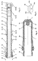
- FIG. 1 In general, a plasma electrode for a plasma arc torch is shown, wherein an approximately hollow cylindrical electrode body 1 in the region of a flange 3 carries seals 2, with which it is sealingly inserted into a housing not shown in detail.
- seals 2 With which it is sealingly inserted into a housing not shown in detail.
- the exact type of attachment results from the EP 2 082 622 B ,
- the electrode body 1 has according to FIG. 4 a central inner bore 28 and forms on its front side an approximately cylindrical electrode core holder 12, which is material integral with the rest of the material.
- an electrode core 11 is used, the z. B. hafnium consists.
- the electrode core 11 extends through the entire electrode core holder 12, while in the embodiment according to FIG. 4 the electrode core 11 is shorter.
- the electrode core holder 12 is as narrow as possible in its cross-section and otherwise cylindrical in order to allow a good flow of the cooling medium over its surfaces, as in FIG. 1 is shown.
- the rear end of the electrode core holder 12 forms according to FIG. 4 an end-face abutment surface 26 for a spacer means, which is installed in the cooling tube 4.
- the cooling tube 4 in turn consists of a hollow cylindrical metal or plastic body, in whose inner bore 34 (s. FIG. 3 ) a cooling channel 9 is provided for the flow of a cooling medium, which flows in the direction of arrow 10 in the inner bore 34.
- the cooling tube 4 has at its rear end a screw thread 7 and also a seal with a seal 6, which is arranged in the region of a flange 5.
- the seal with the seal 6 takes place in a manner not shown in such a way that flows in the direction of arrow 17 from the return 8 serving cooling channel in an associated outlet 18 and is removed there.
- a plug connection can also be provided.
- a spacer plate 13 is arranged, which in the illustrated embodiment according to FIG. 1 material integral with the material of the cooling tube 4 is formed. It is made in the machining of the cooling tube together with this.
- the shim 13 is in FIG. 2 shown in plan view. It consists essentially of a center cross 19, which is material integral with the material of the cooling tube 4 and consists of a plurality of manufacturized materials 14, which are arranged in the space between the intersecting beams of the center cross 19.
- the center cross 19 forms a centric abutment surface 20 which corresponds to the abutment surface 26 of the electrode core holder 12 FIG. 4 assigned.
- each quadrant of the center cross limiting flow recesses 14 and individual flow holes may be provided, which consist of one or more holes per quadrant.
- the flow conditions are in FIG. 3 shown in more detail.
- the cooling medium is deflected in the direction of arrow 21 and flows back on the outer circumference of the cooling tube 4 in the direction of arrow 22 and in this case approximately two-thirds of the length of the cooling tube strikes pressure wing 23 arranged there.
- pressure vanes 23 are arranged uniformly distributed on the circumference of the cooling tube and lie in the cooling channel 8, thus directed in the longitudinal direction of the cooling tube to the rear, against the screw fastening 7 directed pressure force 25 on this erbefest Trent.
- FIG. 3 shows as a modified embodiment the case in which the pressure vanes 23 are not formed as straight lugs, but bevelled lie in the cooling channel 8.
- bevel a spiral vortex flow is generated downstream of the pressure vanes 23, whereby a additional rotational component is exerted on the cooling tube 4 and this rotational component is directed so that the screw is solidified with the screw thread 7.
- FIG. 6 shows the front view of the pressure wings 23 a just formed, which accordingly only a straight, axially directed pressure force 25 in the in FIG. 3 drawn arrow direction in the direction of the rear screw with the screw thread 7 generate.
- FIG. 5 shows that pressure vanes 23, 23, 23b, 23c, 23 d of any kind can also be arranged on the outer circumference of a ring 36.
- the ring 36 may be formed as a plug-in ring, which can be plugged or snapped onto the outer circumference of the cooling tube 4.
- the FIG. 8 show another embodiment of the ring 36 which is provided with an internal thread 37 which can be screwed onto an associated external thread on the cooling tube 4.
- FIG. 9 shows as a further embodiment propeller-shaped pressure vanes 23b, which reinforce the turbulent flow 24 and generate a directed in the closing direction of torque 30 to the screw with the screw thread 7.
- the electrode body 1 in turn carries a ringbefest Trent 29 at its rear end, with which it is sealingly screwed into an associated housing part of the plasma arc burner. Instead, a plug or clamp connection may be present.
- FIGS. 10 and 11 show a releasable attachment of the spacer plate 13, wherein uniformly distributed around the circumference individual spacer nubs 32 are formed by material displacement of the material of the cooling tube, and at a distance thereof further locking nubs 33, z. B. as three evenly distributed on the circumference arranged locking nubs, may be formed, resulting in a locking receptacle between the nubs 32, 33 results in the engagement of an inserted in the direction of arrow 31 shim 13.
- FIG. 11 shows as a modified embodiment that instead of the stop nubs 32, 33 at the same location an internal thread in the cooling tube can be arranged and the spacer plate 13 has a thread 35 on the outer circumference, so that the spacer easily with a suitable tool with its external thread into the internal thread of the cooling tube can be screwed in and fixed there.
- spacer disc 13 can also be clipped into an undercut groove machined on the inner circumference of the cooling tube or screwed into an internal thread machined there.
- FIGS. 12 and 13 is a section through the front end of the cooling tube at the level of FIG. 10 shown spacer 13 is shown.
- the figure 12 shows that the spacer plate 13 in its simplest form can also be formed as a transversely passing through the bore of the cooling tube wire or rod 13a.
- the wire or rod 13 a is used in mutually aligned bores 38 in the cooling tube 4, soldered or pressed.
- the rod or wire 13a may be made of plastic or metal.
- FIG. 13 shows that several, intersecting wires or rods 13a may be inserted in the inner bore.
- the said parts can also be engaged in an undercut groove on the inner circumference of the cooling tube. They can also be connected to each other in the middle region and form a cross, which is locked or clamped in the undercut groove.
Landscapes
- Physics & Mathematics (AREA)
- Engineering & Computer Science (AREA)
- Plasma & Fusion (AREA)
- Spectroscopy & Molecular Physics (AREA)
- Plasma Technology (AREA)
Description
- Die Erfindung betrifft eine Elektrode mit eingesetztem Kühlrohr für einen Plasma-Lichtbogenbrenner nach dem Oberbegriff des Patentanspruchs 1.
- Eine Plasma-Elektrode mit eingesetztem Kühlrohr ist beispielsweise mit dem Gegenstand der
EP 2 082 622 B1 oderWO 2010/115397 A + bekannt geworden. Auf die dortige Offenbarung und die Funktionsweise eines Plasma-Lichtbogenbrenners wird Bezug genommen. Sie soll vollumfänglich von der Offenbarung der vorliegenden Erfindung umfasst sein. - Beim Betrieb von Plasma-Lichtbogenbrennern besteht das Problem, dass der an der Vorderseite des Elektrodenkörpers in einem Elektrodenkernhalter angeordnete Elektrodenkern einer bis zu 1500 °C erreichenden Arbeitstemperatur ausgesetzt ist. Aus diesem Grund muss der Elektrodenkörper der Plasma-Elektrode ausreichend gekühlt werden. Dies wird nach dem Gegenstand der
EP 2 082 622 B1 dadurch bewerkstelligt, dass in die als hohlzylindrischer Elektrodenkörper ausgebildete Plasma-Elektrode ein ebenfalls hohlzylindrisches Kühlrohr eingesetzt ist, das im Vor- und Rücklauf von einem Kühlmittelstrom durchflossen ist. Der Kühlmittelstrom wird durch die zentrale Innenbohrung des Kühlrohres nach vorne in Richtung auf den Elektrodenkernhalter des Elektrodenkörpers geleitet, wo er am Grund des Elektrodenkörpers umgelenkt wird und an der Außenseite des Kühlrohres und am Innenumfang des Elektrodenkörpers wieder zurückfließt. - Das Kühlrohr ist einer beträchtlichen Wärmeausdehnung ausgesetzt, und es muss dafür gesorgt werden, dass es nicht bei seiner Wärmeausdehnung den Kühlmittelstrom unterbricht. Zu diesem Zweck schlägt die
EP 2 082 622 B1 vor, die vordere Stirnseite des Kühlrohres, die nächst dem Elektrodenkernhalter sitzt, mit einem Abstandshalter zu versehen. - Der Abstandshalter ist am Grund des Elektrodenkörpers als einlegbare Scheibe oder als sich kreuzende Stäbe ausgebildet und soll eine Anschlagfläche für das vordere Ende des Kühlrohres am Elektrodenkörper ausbilden.
- Nachteil dieses bekannten Abstandshalters ist jedoch, dass er als gesondertes Teil in den Elektrodenkörper eingelegt oder eingepresst werden muss, was mit erhöhtem Aufwand verbunden ist.
- Weiterer Nachteil ist, dass er nicht Teil des Kühlrohres ist und nicht an der Längenausdehnung des Kühlrohrs teilnimmt, womit die Gefahr besteht, dass das vordere Ende des Kühlrohres abdichtend auf dem Abstandshalter aufsitzt und hiermit der Kühlmittelstrom beeinträchtigt ist.
- Der Erfindung liegt deshalb die Aufgabe zugrunde, eine Plasma-Elektrode für einen Plasma-Lichtbogenbrenner der eingangs genannten Art so weiterzubilden, dass eine verbesserte Abstandshalterung für das Kühlrohr im Innenraum des hohlzylindrischen Elektrodenkörpers gewährleistet ist.
- Zur Lösung der gestellten Aufgabe ist die Erfindung durch die technische Lehre des Anspruches 1 gekennzeichnet.
- Wesentliches Merkmal der Erfindung ist, dass das Kühlrohr - auch wenn es in eine Längsverschiebung erfährt, stets in seine hintere, elektrodenseitige Halterung zurück gedrückt wird. Dies erfolgt durch den Druck des auf das Kühlrohr wirkenden Kühlmediums und am Kühlrohr angeordnete Druckflügel.
- Auf diese Weise wird eine optimale Umströmung des gesamten Elektrodenkernhalters und des dort auf eine Betriebstemperatur über 1000 °C aufgeheizten Elektrodenkern gewährleistet.
- Es hat sich herausgestellt, dass eine optimale Führung des Kühlmittelstromes - unabhängig von temperaturbedingten Längenänderungen des Kühlrohres - dann erfolgt, wenn die Abstandsscheibe nicht abstandshaltend an der vorderen Stirnfläche des Elektrodenkernhalters der Plasma-Elektrode anliegt.
- Es sollte also möglichst dafür gesorgt werden, dass das Kühlrohr nach hinten in Richtung auf seine hintere Halterung zurückgezogen bleibt und die Abstandsscheibe nur im Bedarfsfall mit ihrer Anschlagfläche an der zugeordneten, gegenüberliegenden Anschlagfläche des Elektrodenkernhalters zur Anlage kommt.
- Um dies zu erreichen, wird nach dem zweiten Merkmal der Erfindung beansprucht, dass eine selbsttätige Rückzugkraft auf das Kühlrohr wirkt, welche Rückzugkraft - in Richtung auf die rückseitige Halterung des Kühlrohrs - durch den Kühlmittelstrom selbst ausgeübt wird.
- Erfindungsgemäß ist vorgesehen, dass im Rücklaufkanal, der am Außenumfang des Kühlrohres und am Innenumfang der hohlzylindrischen Bohrung des Elektrodenkörpers gebildet ist, Druckflügel angeordnet sind, die mit dem Außenumfang des Kühlrohres verbunden sind.
- Weil diese Druckflügel im Rücklaufkanal liegen, werden sie von dem zurücklaufenden Kühlmedium beströmt und drücken das Kühlrohr in Richtung seiner Längsachse gegen seine hintere, elektrodenseitige Befestigung, die als Schraub- oder Steckbefestigung ausgebildet sein kann.
- Damit wird ein eventuelles axiales Spiel in der Schraub- oder Steckbefestigung zwischen dem Kühlrohr und dem Elektrodenkörper aufgehoben, weil das Kühlrohr bedingt durch den Druck des Kühlmediums und durch die im Rücklaufkanal angeordneten Druckflügel stets mit einer gleichbleibenden Vorspannungskraft in seiner elektrodenseitigen Halterung gepresst wird.
- Damit wird das Kühlrohr immer stets nach hinten in seine elektrodenseitige Halterung gedrückt und die vordere, dem Anschlag an dem Elektrodenkernhalter dienende Abstandsscheibe wird von dem Elektrodenkernhalter abgehoben und bleibt in einem bestimmten Abstand von diesem Elektrodenkernhalter.
- Durch diese Abstandsbildung fließt das Kühlmittel auch über die Stirnseite des Elektrodenkernhalters, weil die Abstandsscheibe einen bestimmten Spalt zu dieser Stirnseite des Elektrodenkernhalters einnimmt und somit einen optimierten Kühlmittelstrom über den Elektrodenkernhalter erlaubt.
- Die im Rücklaufkanal angeordneten Druckflügel, die entweder werkstoffeinstückig oder lösbar mit dem Außenumfang des Kühlrohrs verbunden sind, können gerade ausgebildet sein, also mit ihren Flügelflächen senkrecht im Kühlmittelstrom liegen, sodass eine zusätzliche zirkulare Wirbelströmung im Rücklauf-Kühlkanal vermieden wird.
- In diesem Fall wird auch eine gerade, in Längsrichtung auf das Kühlrohr gegen die Befestigung des Kühlrohrs im Elektrodenkörper gerichtete Kraftkomponente auf das Kühlrohr erzeugt. Damit wird die Gewindeschraubverbindung in axialer Richtung vorgespannt.
- Wenn hingegen in einer Weiterbildung dieser Ausführungsform die Druckflügel noch angeschrägt bezüglich der Längsachse der Kühlmittelströmung sind, strömt das im Rücklauf zurückströmende Kühlmedium spiralförmig stromabwärts der Druckflügel in Richtung auf den Kühlmittelauslass zurück, wodurch neben der geraden, in axialer Richtung des Kühlrohres erzeugten Kraftkomponente noch eine drehende (zirkuläre) Kraftkomponente auf das Kühlrohr erzeugt wird.
- Die Drehrichtung dieser Kraftkomponente ist bevorzugt so gerichtet, dass eine eventuelle Gewindeschraubverbindung zwischen dem Kühlrohr und dem Elektrodenkörper im Sinne einer Verfestigung noch zusätzlich in Drehrichtung vorgespannt wird. Es kommt somit zu einer axialen und einer radialen Vorspannung der Gewindeschraubverbindung zwischen dem Elektrodenkörper und dem Kühlrohr.
- Damit wird einerseits jegliches Spiel aus dieser Gewindeschraubverbindung entfernt, und andererseits wird diese Gewindeschraubverbindung noch zusätzlich in Festdrehrichtung drehend vorgespannt, wodurch noch eine zusätzliche Sicherung dieser Gewindeschraubverbindung erfolgt.
- Bei solchen, in Strömungsrichtung des Rücklaufkanals angeschrägten Druckflügeln kann es auch vorgesehen sein, dass die Druckflügel nicht nur angeschrägt sind, sondern auch in der Art von Propellern eine stromabwärts der Druckflügel entstehende Wirbelströmung des Kühlmediums erzeugen, wodurch das Kühlmedium spiralförmig oder schraubenförmig um den Außenumfang des Kühlrohres geleitet wird, und hier einerseits das Kühlrohr - wie vorher angegeben - eine zusätzliche Drehkraft-Komponente erhält und der zurückströmende Kühlmittelstrom noch einen Drall erhält, der eine beschleunigte Abführung des Kühlmittelstromes aus dem Kühlmittelauslauf bewerkstelligt.
- Der Erfindungsgegenstand der vorliegenden Erfindung ergibt sich nicht nur aus dem Gegenstand der einzelnen Patentansprüche, sondern auch aus der Kombination der einzelnen Patentansprüche untereinander.
- Alle in den Unterlagen, einschließlich der Zusammenfassung offenbarten Angaben und Merkmale, insbesondere die in den Zeichnungen dargestellte räumliche Ausbildung, werden als erfindungswesentlich beansprucht, soweit sie einzeln oder in Kombination gegenüber dem Stand der Technik neu sind.
- Im Folgenden wird die Erfindung anhand von mehrere Ausführungswege darstellenden Zeichnungen näher erläutert. Hierbei gehen aus den Zeichnungen und ihrer Beschreibung weitere erfindungswesentliche Merkmale und Vorteile der Erfindung hervor.
- Es zeigen:
-
Figur 1 : Längsschnitt durch eine Plasma-Elektrode für einen Plasma-Lichtbogenbrenner in einer ersten Ausführungsform eines Kühlrohres -
Figur 2 : die Stirnansicht auf das inFigur 1 im Schnitt dargestellte Kühlrohr mit Abstandsscheibe -
Figur 3 : der Schnitt durch das Kühlrohr nachFigur 1 in einer abgewandelten Ausführungsform mit Darstellung weiterer Funktionen -
Figur 4 : ein Schnitt durch den Elektrodenkörper gemäßFigur 1 in einer abgewandelten Ausführungsform -
Figur 5 : eine perspektivische Ansicht eines Rings mit Druckflügeln -
Figur 6 : die Stirnansicht auf das Kühlrohr in Höhe der inFigur 3 dargestellten Druckflügel -
Figur 7 : eine gegenüberFigur 5 abgewandelte Ausführungsform von Druckflügeln -
Figur 8 : eine perspektivische Darstellung eines Schraubrings mit Druckflügeln -
Figur 9 : eine gegenüber denFiguren 5 und6 abgewandelte Ausführungsform von Druckflügeln in der Art von Propellerflügeln -
Figur 10 : eine gegenüberFigur 3 abgewandelte Ausführungsform eines Kühlrohres mit einer lösbar eingesetzten Abstandsscheibe -
Figur 11 : perspektivische Darstellung der inFigur 8 lösbar eingesetzten Abstandsscheibe -
Fig. 12 : ein Schnitt durch das vordere Ende des Kühlrohrs mit Darstellung eines Drahtes oder Stabes als Ersatz für die Abstandsscheibe -
Figur 13 : ein Schnitt durch das vordere Ende des Kühlrohrs mit Darstellung mehrerer Drähte oder Stäbe als Ersatz für die Abstandsscheibe - Die folgenden
Figuren 1 bis 5 der vorliegenden Erfindung dienen nur zur allgemeinen Erläuterung der Erfindung und sollen, insbesondere was die Abstandscheibe 13 in Alleinstellung betrifft, nicht am Schutzumfang teilnehmen. - In
Figur 1 ist allgemein eine Plasma-Elektrode für einen Plasma-Lichtbogenbrenner dargestellt, wobei ein etwa hohlzylindrischer Elektrodenkörper 1 im Bereich eines Flansches 3 Dichtungen 2 trägt, mit denen er abdichtend in ein nicht näher dargestelltes Gehäuse eingesteckt ist. Die genaue Art der Befestigung ergibt sich aus derEP 2 082 622 B . - Der Elektrodenkörper 1 weist gemäß
Figur 4 eine zentrische Innenbohrung 28 auf und bildet an seiner vorderen Seite einen etwa zylinderförmigen Elektrodenkernhalter 12, der werkstoffeinstückig mit dem übrigen Material verbunden ist. - Im Elektrodenkernhalter 12 ist ein Elektrodenkern 11 eingesetzt, der z. B. aus Hafnium besteht. Im Ausführungsbeispiel nach
Figur 1 erstreckt sich der Elektrodenkern 11 durch den gesamten Elektrodenkernhalter 12 hindurch, während im Ausführungsbeispiel nachFigur 4 der Elektrodenkern 11 kürzer ausgebildet ist. - Wichtig ist bei beiden Ausführungen nach
Figur 1 und4 , dass der Elektrodenkernhalter 12 möglichst in seinem Querschnitt schmal ausgebildet ist und im Übrigen zylindrisch, um einen guten Fluss des Kühlmediums über seine Oberflächen zu gestatten, wie dies inFigur 1 dargestellt ist. - Das hintere Ende des Elektrodenkernhalters 12 bildet gemäß
Figur 4 eine stirnseitige Anschlagfläche 26 für ein abstandshaltendes Mittel, welches im Kühlrohr 4 eingebaut ist. - Das Kühlrohr 4 besteht wiederum aus einem hohlzylindrischen Metall- oder Kunststoffkörper, in dessen Innenbohrung 34 (s.
Figur 3 ) ein Kühlkanal 9 für den Durchfluss eines Kühlmediums vorgesehen ist, welches in Pfeilrichtung 10 in die Innenbohrung 34 einströmt. - Das Kühlrohr 4 weist an seinem hinteren Ende ein Schraubgewinde 7 auf und ferner eine Abdichtung mit einer Dichtung 6, die im Bereich eines Flansches 5 angeordnet ist.
- Die Abdichtung mit der Dichtung 6 erfolgt in nicht näher dargestellter Weise dergestalt, dass ein in Pfeilrichtung 17 aus dem dem Rücklauf 8 dienenden Kühlkanal in einen zugeordneten Auslauf 18 einströmt und dort entnommen wird. Statt einer Schraubverbindung kann auch eine Steckverbindung vorgesehen sein.
- Erfindungsgemäß ist nun vorgesehen, dass im Innenraum des Kühlrohres 4, im axialen Abstand von der vordersten Spitze 16, eine Abstandsscheibe 13 angeordnet ist, die im gezeigten Ausführungsbeispiel nach
Figur 1 werkstoffeinstückig mit dem Material des Kühlrohres 4 ausgebildet ist. Sie wird bei der spanabhebenden Bearbeitung des Kühlrohres zusammen mit diesem hergestellt. - Die Abstandsscheibe 13 ist in
Figur 2 in Draufsicht dargestellt. Sie besteht im Wesentlichen aus einem Mittenkreuz 19, welches werkstoffeinstückig mit dem Material des Kühlrohres 4 verbunden ist und aus einer Vielzahl von Durchflussausnehmungen 14 besteht, die im Zwischenraum zwischen den sich kreuzenden Balken des Mittenkreuzes 19 angeordnet sind. - Das Mittenkreuz 19 bildet eine zentrische Anschlagfläche 20, die der Anschlagfläche 26 des Elektrodenkernhalters 12 gemäß
Figur 4 zugeordnet ist. Statt der jeden Quadranten des Mittenkreuzes begrenzenden Durchflussausnehmungen 14 können auch einzelne Durchflußbohrungen vorgesehen sein, die pro Quadrant aus einer oder mehreren Bohrungen bestehen.. - Das in Pfeilrichtung 10 in den Vorlauf-Kühlkanal 9 einströmende Kühlmedium durchfließt demgemäß die Durchflussausnehmungen 14 in der Abstandsscheibe 13 und wird am vorderen Ende des Elektrodenkörpers 1 im Bereich einer Umkehrstrecke 15 umgeleitet und strömt dann am Außenumfang des Kühlrohres 3 über den dort angeordneten Kühlkanal 8 als Rücklauf wieder in Pfeilrichtung 17 zurück.
- Die Strömungsverhältnisse sind in
Figur 3 näher dargestellt. - Hierbei ist erkennbar, dass in der Umkehrstrecke 15 das Kühlmedium in Pfeilrichtung 21 umgelenkt wird und am Außenumfang des Kühlrohres 4 in Pfeilrichtung 22 zurückströmt und hierbei etwa nach 2/3 der Länge des Kühlrohres auf dort angeordneten Druckflügel 23 trifft.
- Weil diese Druckflügel 23 gleichmäßig verteilt am Umfang des Kühlrohres angeordnet sind und im Kühlkanal 8 liegen, wird somit eine in Längsrichtung des Kühlrohres nach hinten, gegen dessen Schraubbefestigung 7 gerichtete Druckkraft 25 auf diese Schraubbefestigung ausgeübt. Es können ein, zwei oder mehrere Druckflügel vorhanden sein.
- Die
Figur 3 zeigt als abgewandeltes Ausführungsbeispiel den Fall, bei dem die Druckflügel 23 nicht als gerade Ansätze ausgebildet sind, sondern angeschrägt im Kühlkanal 8 liegen. Durch diese Anschrägung wird eine spiralförmige Wirbelströmung stromabwärts der Druckflügel 23 erzeugt, wodurch eine zusätzliche Rotationskomponente auf das Kühlrohr 4 ausgeübt wird und diese Rotationskomponente so gerichtet ist, dass die Schraubverbindung mit dem Schraubgewinde 7 verfestigt wird. - Die
Figur 6 zeigt die Stirnansicht der gerade ausgebildeten Druckflügel 23a, die demgemäß nur eine gerade, axial gerichtete Druckkraft 25 in der inFigur 3 eingezeichneten Pfeilrichtung in Richtung auf die hintere Schraubverbindung mit dem Schraubgewinde 7 erzeugen. - Wenn hingegen in
Figur 7 die Druckflügel 23a angeschrägt sind, wird eine Wirbelströmung 24 gemäßFigur 3 erzeugt. - Die
Figur 5 zeigt, dass Druckflügel 23, 23, 23b, 23c, 23 d jeglicher Art auch am Außenumfang eines Rings 36 angeordnet sein können. Der Ring 36 kann als Steckring ausgebildet sein, der auf den Außenumfang des Kühlrohrs 4 aufgesteckt oder aufgerastet werden kann. DieFigur 8 zeig eine andere Ausführung des Rings 36, der mit einem Innengewinde 37 versehen ist, welches auf ein zugeordnetes Außengewinde auf dem Kühlrohr 4 aufgeschraubt werden kann. - Die
Figur 9 zeigt als weitere Ausführungsform propellerförmige Druckflügel 23b, welche die Wirbelströmung 24 noch verstärken und ein in Schließrichtung gerichtetes Drehmoment 30 auf die Schraubverbindung mit dem Schraubgewinde 7 erzeugen. - In
Figur 4 ist noch dargestellt, dass der Elektrodenkörper 1 seinerseits eine Schraubbefestigung 29 an seinem hinteren Ende trägt, mit dem er abdichtend in ein zugeordnetes Gehäuseteil des Plasma-Lichtbogenbrenners eingeschraubt ist. Stattdessen kann auch eine Steck- oder Klemmverbindung vorhanden sein. - Am Bohrungsgrund 27 des Elektrodenkörpers 1 wird somit die Umkehrstrecke 15 ausgebildet.
- Die
Figuren 10 und 11 zeigen eine lösbare Befestigung der Abstandsscheibe 13, wobei gleichmäßig am Umfang verteilt einzelne Abstandsnoppen 32 durch Materialverdrängung aus dem Material des Kühlrohres ausgebildet werden, und im Abstand davon weitere Rastnoppen 33, z. B. als drei gleichmäßig am Umfang verteilt angeordnete Rastnoppen, ausgebildet sein können, wodurch sich eine Rastaufnahme zwischen den Noppen 32, 33 für das Einrasten einer in Pfeilrichtung 31 eingeschobenen Abstandsscheibe 13 ergibt. - Die
Figur 11 zeigt als abgewandelte Ausführungsform, dass statt der Anschlagnoppen 32, 33 an der gleichen Stelle ein Innengewinde im Kühlrohr angeordnet sein kann und die Abstandsscheibe 13 ein Gewinde 35 am Außenumfang aufweist, sodass die Abstandsscheibe einfach mit einem geeigneten Werkzeug mit ihrem Außengewinde in das Innengewinde des Kühlrohres eingeschraubt werden kann und dort festgelegt ist. - Es ist nicht zeichnerisch dargestellt, dass die Abstandsscheibe 13 auch in eine am Innenumfang des Kühlrohrs eingearbeitete hinterschnittene Nut eingeklipst oder in ein dort eingearbeitetes Innengewinde eingeschraubt werden kann.
- Ebenso ist es möglich, eine Schulter verringerten Durchmessers am Innenumfang des Kühlrohrs einzuarbeiten und die Abstandsscheibe 13 mit ihrem Außenumfang an dieser Schulter in axialer Richtung zur Anlage zu bringen. Der Sitz der Abstandsscheibe 13 an dieser Schulter kann dann durch einen in den Innenumfang eingeschraubten Schraubring oder durch einen Sprengring gesichert werden, der in einer Nut eingerastet wird, die in axialer Richtung vor der die Abstandsscheibe haltenden Schulter angeordnet ist.
- In den
Figuren 12 und 13 ist ein Schnitt durch das vordere Ende des Kühlrohrs in Höhe der inFigur 10 dargestellten Abstandsscheibe 13 dargestellt. DieFigur 12 zeigt, dass die Abstandsscheibe 13 in ihrer einfachsten Form auch als quer die Bohrung des Kühlrohrs durchsetzender Draht oder Stab 13a ausgebildet sein kann. Der Draht oder Stab 13 a ist in zueinander fluchtenden Bohrungen 38 im Kühlrohr 4 eingesetzt, eingelötet oder eingepresst. Der Stab oder Draht 13a kann aus Kunststoff oder Metall bestehen. - Die
Figur 13 zeigt, dass auch mehrere, sich kreuzende Drähte oder Stäbe 13a in der Innenbohrung eingesetzt sein können. Die genannten Teile können auch in einer hinterschnittenen Nut am Innenumfang des Kühlrohrs eingerastet sein. Sie können auch im Mittenbereich mit einander verbunden sein und ein Kreuz ausbilden, welches in die hinterschnittene Nut eingerastet oder eingespannt ist. -
- 1
- Elektrodenkörper
- 2
- Dichtung
- 3
- Flansch
- 4
- Kühlrohr
- 5
- Flansch
- 6
- Dichtung
- 7
- Schraubgewinde
- 8
- Kühlkanal (Rücklauf)
- 9
- Kühlkanal (Vorlauf)
- 10
- Pfeilrichtung
- 11
- Elektrodenkern
- 12
- Elektrodenkernhalter
- 13
- Abstandsscheibe oder Abstandshalter 13a Drähte oder Stäbe
- 14
- Durchflussausnehmung
- 15
- Umkehrstrecke
- 16
- Spitze (von 4)
- 17
- Pfeilrichtung
- 18
- Auslauf
- 19
- Mittenkreuz
- 20
- Anschlagfläche
- 21
- Pfeilrichtung
- 22
- Pfeilrichtung
- 23
- Druckflügel a, b
- 24
- Wirbelströmung
- 25
- Druckkraft
- 26
- Anschlagfläche
- 27
- Bohrungsgrund
- 28
- Innenbohrung (von 1)
- 29
- Schraubbefestigung
- 30
- Drehmoment
- 31
- Pfeilrichtung
- 32
- Anschlagnoppe
- 33
- Rastnoppe
- 34
- Innenbohrung (von 4)
- 35
- Gewinde (von 13)
- 36
- Ring
- 37
- Innengewinde
- 38
- Bohrung
Claims (13)
- Elektrode für einen Plasma-Lichtbogenbrenner, bestehend aus einem hohlzylindrischen Elektrodenkörper (1) mit einer zentralen Innenbohrung (28), an deren vorderen Ende ein Elektrodenkernhalter (12) mit einem dort eingesetzten Elektrodenkern (11) angeordnet ist, und einem in die Innenbohrung (28) eingesetzten, hohlzylindrischen Kühlrohr (4), welches in seiner Innenbohrung (34) einen als Vorlauf ausgebildeten Kühlkanal (9) und im Zwischenraum zwischen seinem Außenumfang und dem Innenumfang des Elektrodenkörpers (1) einen als Rücklauf ausgebildeten Kühlkanal (8) ausbildet, dadurch gekennzeichnet, dass am Außenumfang des Kühlrohrs (4) mindestens zwei am Umfang versetzt zueinander angeordnete Druckflügel (23, 23a, 23b, 23c, 23d) angeordnet sind, welche vom Kühlmedium im als Rücklauf ausgebildeten Kühlkanal (8) beaufschlagt sind und das Kühlrohr (4) gegen seine elektrodenseitige Befestigung drücken.
- Elektrode nach Anspruch 1, dadurch gekennzeichnet, dass die Druckflügel (23, 23a, 23b, 23c, 23d) bezüglich der Längsachse der Kühlmittelströmung angeschrägt sind.
- Elektrode nach Anspruch 2, dadurch gekennzeichnet, dass die Druckflügel (23, 23a, 23b, 23c, 23d) dergestalt ausgebildet sind, dass eine stromabwärts des Kühlkanals (8) gerichtete Wirbelströmung (24) erzeugt ist.
- Elektrode nach einem der Ansprüche 1 bis 3, dadurch gekennzeichnet, dass die elektrodenseitige Befestigung als Schraub- oder Steckbefestigung ausgebildet ist.
- Elektrode nach einem der Ansprüche 1 bis 4, dadurch gekennzeichnet, dass die Druckflügel (23a) als in Richtung zur Längsachse des Kühlrohrs (4) angeschrägte Lappen ausgebildet sind.
- Elektrode nach einem der Ansprüche 1 bis 5, dadurch gekennzeichnet, dass die Druckflügel (23b) als in Richtung zur Längsachse des Kühlrohrs (4) angeschrägte Propellerflügel ausgebildet sind.
- Elektrode nach einem der Ansprüche 1 bis 6, dadurch gekennzeichnet, dass das Kühlrohr (4) an seiner dem Elektrodenkernhalter (12) zugewandeten Innenseite abstandshaltende Mittel aufweist, die zur stirnseitigen Anlage am Elektrodenkernhalter (12) geeignet sind.
- Elektrode nach Anspruch 7, dadurch gekennzeichnet, dass das abstandshaltende Mittel als Abstandsscheibe (13) ausgebildet ist.
- Elektrode nach einem der Ansprüche 1 bis 8, dadurch gekennzeichnet, dass die Druckflügel (23, 23a, 23b, 23c, 23d) werkstoffeinstückig mit dem Kühlrohr (4) verbunden sind.
- Elektrode nach einem der Ansprüche 1 bis 8, dadurch gekennzeichnet, dass die Druckflügel (23, 23a, 23b, 23c, 23d) lösbar mit dem Kühlrohr (4) verbunden sind.
- Elektrode nach Anspruch 10, dadurch gekennzeichnet, dass die Druckflügel (23, 23a, 23b, 23c, 23d) am Aussenumfang eines Rings (36) angeordnet sind.
- Elektrode nach Anspruch 11, dadurch gekennzeichnet, dass der Ring (36) als Steckring ausgebildet ist und auf das Kühlrohr aufsteckbar oder einrastbar ist.
- Elektrode nach Anspruch 11, dadurch gekennzeichnet, dass der Ring (36) mit einem Innengewinde (37) versehen ist, welches auf ein zugeordnetes Außengewinde auf das Kühlrohr (4) aufschraubbar ist.
Priority Applications (1)
| Application Number | Priority Date | Filing Date | Title |
|---|---|---|---|
| EP13005830.8A EP2734015B1 (de) | 2012-05-07 | 2012-05-07 | Kühlrohr für einen Plasma-Lichtbogenbrenner |
Applications Claiming Priority (2)
| Application Number | Priority Date | Filing Date | Title |
|---|---|---|---|
| EP12003596.9A EP2663167B1 (de) | 2012-05-07 | 2012-05-07 | Kühlrohr für einen Plasma-Lichtbogenbrenner und Abstandshalter |
| EP13005830.8A EP2734015B1 (de) | 2012-05-07 | 2012-05-07 | Kühlrohr für einen Plasma-Lichtbogenbrenner |
Related Parent Applications (2)
| Application Number | Title | Priority Date | Filing Date |
|---|---|---|---|
| EP12003596.9A Division EP2663167B1 (de) | 2012-05-07 | 2012-05-07 | Kühlrohr für einen Plasma-Lichtbogenbrenner und Abstandshalter |
| EP12003596.9A Division-Into EP2663167B1 (de) | 2012-05-07 | 2012-05-07 | Kühlrohr für einen Plasma-Lichtbogenbrenner und Abstandshalter |
Publications (3)
| Publication Number | Publication Date |
|---|---|
| EP2734015A2 EP2734015A2 (de) | 2014-05-21 |
| EP2734015A3 EP2734015A3 (de) | 2014-10-29 |
| EP2734015B1 true EP2734015B1 (de) | 2016-10-19 |
Family
ID=48485099
Family Applications (2)
| Application Number | Title | Priority Date | Filing Date |
|---|---|---|---|
| EP12003596.9A Not-in-force EP2663167B1 (de) | 2012-05-07 | 2012-05-07 | Kühlrohr für einen Plasma-Lichtbogenbrenner und Abstandshalter |
| EP13005830.8A Revoked EP2734015B1 (de) | 2012-05-07 | 2012-05-07 | Kühlrohr für einen Plasma-Lichtbogenbrenner |
Family Applications Before (1)
| Application Number | Title | Priority Date | Filing Date |
|---|---|---|---|
| EP12003596.9A Not-in-force EP2663167B1 (de) | 2012-05-07 | 2012-05-07 | Kühlrohr für einen Plasma-Lichtbogenbrenner und Abstandshalter |
Country Status (3)
| Country | Link |
|---|---|
| US (1) | US9661731B2 (de) |
| EP (2) | EP2663167B1 (de) |
| WO (1) | WO2013167244A2 (de) |
Families Citing this family (4)
| Publication number | Priority date | Publication date | Assignee | Title |
|---|---|---|---|---|
| US11062816B2 (en) * | 2014-08-11 | 2021-07-13 | Best Theratronics Ltd. | Target, apparatus and process for the manufacture of molybdenum-100 targets |
| EP3437440B1 (de) * | 2016-03-28 | 2024-07-03 | Hypertherm, Inc. | Verbesserte elektrode für ein plasmalichtbogenschneidsystem und betriebsverfahren |
| DE102016215712A1 (de) * | 2016-08-22 | 2018-02-22 | Siemens Aktiengesellschaft | Vorrichtung und Verfahren zur Erzeugung eines elektrischen Plasmas |
| US11986900B2 (en) | 2020-03-16 | 2024-05-21 | Hypertherm, Inc. | Cathode seated liquid coolant tube for a plasma arc cutting system |
Family Cites Families (11)
| Publication number | Priority date | Publication date | Assignee | Title |
|---|---|---|---|---|
| US3668354A (en) * | 1970-12-04 | 1972-06-06 | Park Ohio Industries Inc | Radio frequency transfer switch |
| FR2534106A1 (fr) | 1982-10-01 | 1984-04-06 | Soudure Autogene Francaise | Torche a plasma monogaz |
| GB8615759D0 (en) * | 1986-06-27 | 1986-08-06 | W T C Holdings Ltd | Air plasma arc torch |
| US5756959A (en) * | 1996-10-28 | 1998-05-26 | Hypertherm, Inc. | Coolant tube for use in a liquid-cooled electrode disposed in a plasma arc torch |
| ITRM20010291A1 (it) * | 2001-05-29 | 2002-11-29 | Ct Sviluppo Materiali Spa | Torcia al plasma |
| US20080116179A1 (en) * | 2003-04-11 | 2008-05-22 | Hypertherm, Inc. | Method and apparatus for alignment of components of a plasma arc torch |
| US6946617B2 (en) * | 2003-04-11 | 2005-09-20 | Hypertherm, Inc. | Method and apparatus for alignment of components of a plasma arc torch |
| DE102009016932B4 (de) * | 2009-04-08 | 2013-06-20 | Kjellberg Finsterwalde Plasma Und Maschinen Gmbh | Kühlrohre und Elektrodenaufnahme für einen Lichtbogenplasmabrenner sowie Anordnungen aus denselben und Lichtbogenplasmabrenner mit denselben |
| US8546719B2 (en) * | 2010-12-13 | 2013-10-01 | The Esab Group, Inc. | Method and plasma arc torch system for marking and cutting workpieces with the same set of consumables |
| EP2681974B1 (de) * | 2011-02-28 | 2020-06-17 | Victor Equipment Company | Plasmaschneidspitze mit erweiterten kühlkanälen |
| US9114475B2 (en) * | 2012-03-15 | 2015-08-25 | Holma Ag | Plasma electrode for a plasma cutting device |
-
2012
- 2012-05-07 EP EP12003596.9A patent/EP2663167B1/de not_active Not-in-force
- 2012-05-07 EP EP13005830.8A patent/EP2734015B1/de not_active Revoked
-
2013
- 2013-04-27 WO PCT/EP2013/001277 patent/WO2013167244A2/de not_active Ceased
- 2013-04-27 US US14/361,882 patent/US9661731B2/en not_active Expired - Fee Related
Also Published As
| Publication number | Publication date |
|---|---|
| WO2013167244A3 (de) | 2014-01-03 |
| EP2663167A1 (de) | 2013-11-13 |
| WO2013167244A4 (de) | 2014-02-13 |
| EP2734015A2 (de) | 2014-05-21 |
| US20150102020A1 (en) | 2015-04-16 |
| US9661731B2 (en) | 2017-05-23 |
| WO2013167244A2 (de) | 2013-11-14 |
| EP2734015A3 (de) | 2014-10-29 |
| EP2663167B1 (de) | 2016-12-21 |
Similar Documents
| Publication | Publication Date | Title |
|---|---|---|
| DE102011078508B4 (de) | Vollkegeldüse | |
| EP0956920B1 (de) | Futter für drehantreibbare Werkzeuge, insbesondere Bohrer, Gewindebohrer o.dgl. | |
| DE2656151C2 (de) | Vorrichtung zum Abtrennen von Festkörperverunreinigungen aus einem Gasstrom | |
| DE1938305A1 (de) | Duesen- und Verteileranordnung fuer Gasturbinen | |
| EP2663167B1 (de) | Kühlrohr für einen Plasma-Lichtbogenbrenner und Abstandshalter | |
| DE102014116411A1 (de) | Drallkörper und Brenner mit Drallkörper sowie Verfahren zur Herstellung des Drallkörpers | |
| DE2559302A1 (de) | Drehbare rohrverbindung | |
| DE29724492U1 (de) | Vorrichtung zum Aufteilen einer mittels einer Gasströmung transportierten viskosen Flüssigkeit | |
| EP1356868B1 (de) | Zweistoffsprühdüse mit wechselbarem Einsatz | |
| DE3046471A1 (de) | Duesenkern zum einbau in einen duesenkoerper von heisskanalspritzduesen fuer eine kunststoffspritzgiessvorrichtung | |
| DE102009059108A1 (de) | Elektrode mit Kühlrohr für eine Plasmaschneidvorrichtung | |
| DE202016103825U1 (de) | Drallkörper sowie Kegeldüse mit einem solchen Drallkörper | |
| EP0096083B1 (de) | Rundlaufendes Schneidwerkzeug, insbesondere zum Stranggranulieren von Kunststoffmaterial | |
| EP0428496B1 (de) | Verbindung für Bauteile aus unterschiedlichen Materialien | |
| EP2996849B1 (de) | Extrusionskopf mit lochplatte einer granulieranlage | |
| DE202014105403U1 (de) | Drallkörper und Brenner mit Drallkörper | |
| EP2113728A1 (de) | Koaxialsonde für die Erdwärmegewinnung | |
| DE102006056663B4 (de) | Gewindeverbindung für Bohrgestänge | |
| EP2642832A1 (de) | Plasma-Elektrode für einen Plasmalichtbogenbrenner mit auswechselbarer Elektrodenspitze | |
| DE19650983C2 (de) | Kühlvorrichtung | |
| DE2757554B2 (de) | Schreibeinsatz für Röhrchenschreibgeräte | |
| EP2640167B1 (de) | Plasmaelektrode für eine Plasma-Schneidvorrichtung | |
| DE3122404A1 (de) | Brenner zum thermochemischen brennen und/oder abhobeln von werkstuecken aus stahl | |
| DE1937735C (de) | Vorrichtung zum Mischen zweier Medien, deren Temperaturen stark voneinander abweichen | |
| DE8130102U1 (de) | Widerstands-heizelement zur anordnung einer bohrung eines zu beheizenden werkstueckes |
Legal Events
| Date | Code | Title | Description |
|---|---|---|---|
| PUAI | Public reference made under article 153(3) epc to a published international application that has entered the european phase |
Free format text: ORIGINAL CODE: 0009012 |
|
| 17P | Request for examination filed |
Effective date: 20131216 |
|
| AC | Divisional application: reference to earlier application |
Ref document number: 2663167 Country of ref document: EP Kind code of ref document: P |
|
| AK | Designated contracting states |
Kind code of ref document: A2 Designated state(s): AL AT BE BG CH CY CZ DE DK EE ES FI FR GB GR HR HU IE IS IT LI LT LU LV MC MK MT NL NO PL PT RO RS SE SI SK SM TR |
|
| PUAL | Search report despatched |
Free format text: ORIGINAL CODE: 0009013 |
|
| AK | Designated contracting states |
Kind code of ref document: A3 Designated state(s): AL AT BE BG CH CY CZ DE DK EE ES FI FR GB GR HR HU IE IS IT LI LT LU LV MC MK MT NL NO PL PT RO RS SE SI SK SM TR |
|
| RIC1 | Information provided on ipc code assigned before grant |
Ipc: H05H 1/34 20060101AFI20140926BHEP |
|
| R17P | Request for examination filed (corrected) |
Effective date: 20150211 |
|
| RBV | Designated contracting states (corrected) |
Designated state(s): AL AT BE BG CH CY CZ DE DK EE ES FI FR GB GR HR HU IE IS IT LI LT LU LV MC MK MT NL NO PL PT RO RS SE SI SK SM TR |
|
| GRAP | Despatch of communication of intention to grant a patent |
Free format text: ORIGINAL CODE: EPIDOSNIGR1 |
|
| INTG | Intention to grant announced |
Effective date: 20160428 |
|
| GRAS | Grant fee paid |
Free format text: ORIGINAL CODE: EPIDOSNIGR3 |
|
| GRAA | (expected) grant |
Free format text: ORIGINAL CODE: 0009210 |
|
| AC | Divisional application: reference to earlier application |
Ref document number: 2663167 Country of ref document: EP Kind code of ref document: P |
|
| AK | Designated contracting states |
Kind code of ref document: B1 Designated state(s): AL AT BE BG CH CY CZ DE DK EE ES FI FR GB GR HR HU IE IS IT LI LT LU LV MC MK MT NL NO PL PT RO RS SE SI SK SM TR |
|
| REG | Reference to a national code |
Ref country code: GB Ref legal event code: FG4D Free format text: NOT ENGLISH |
|
| REG | Reference to a national code |
Ref country code: CH Ref legal event code: EP |
|
| REG | Reference to a national code |
Ref country code: AT Ref legal event code: REF Ref document number: 839275 Country of ref document: AT Kind code of ref document: T Effective date: 20161115 |
|
| REG | Reference to a national code |
Ref country code: IE Ref legal event code: FG4D Free format text: LANGUAGE OF EP DOCUMENT: GERMAN |
|
| REG | Reference to a national code |
Ref country code: DE Ref legal event code: R096 Ref document number: 502012008603 Country of ref document: DE |
|
| REG | Reference to a national code |
Ref country code: NL Ref legal event code: FP |
|
| REG | Reference to a national code |
Ref country code: LT Ref legal event code: MG4D |
|
| PG25 | Lapsed in a contracting state [announced via postgrant information from national office to epo] |
Ref country code: LV Free format text: LAPSE BECAUSE OF FAILURE TO SUBMIT A TRANSLATION OF THE DESCRIPTION OR TO PAY THE FEE WITHIN THE PRESCRIBED TIME-LIMIT Effective date: 20161019 |
|
| PG25 | Lapsed in a contracting state [announced via postgrant information from national office to epo] |
Ref country code: NO Free format text: LAPSE BECAUSE OF FAILURE TO SUBMIT A TRANSLATION OF THE DESCRIPTION OR TO PAY THE FEE WITHIN THE PRESCRIBED TIME-LIMIT Effective date: 20170119 Ref country code: GR Free format text: LAPSE BECAUSE OF FAILURE TO SUBMIT A TRANSLATION OF THE DESCRIPTION OR TO PAY THE FEE WITHIN THE PRESCRIBED TIME-LIMIT Effective date: 20170120 Ref country code: SE Free format text: LAPSE BECAUSE OF FAILURE TO SUBMIT A TRANSLATION OF THE DESCRIPTION OR TO PAY THE FEE WITHIN THE PRESCRIBED TIME-LIMIT Effective date: 20161019 Ref country code: LT Free format text: LAPSE BECAUSE OF FAILURE TO SUBMIT A TRANSLATION OF THE DESCRIPTION OR TO PAY THE FEE WITHIN THE PRESCRIBED TIME-LIMIT Effective date: 20161019 |
|
| PG25 | Lapsed in a contracting state [announced via postgrant information from national office to epo] |
Ref country code: HR Free format text: LAPSE BECAUSE OF FAILURE TO SUBMIT A TRANSLATION OF THE DESCRIPTION OR TO PAY THE FEE WITHIN THE PRESCRIBED TIME-LIMIT Effective date: 20161019 Ref country code: RS Free format text: LAPSE BECAUSE OF FAILURE TO SUBMIT A TRANSLATION OF THE DESCRIPTION OR TO PAY THE FEE WITHIN THE PRESCRIBED TIME-LIMIT Effective date: 20161019 Ref country code: IS Free format text: LAPSE BECAUSE OF FAILURE TO SUBMIT A TRANSLATION OF THE DESCRIPTION OR TO PAY THE FEE WITHIN THE PRESCRIBED TIME-LIMIT Effective date: 20170219 Ref country code: FI Free format text: LAPSE BECAUSE OF FAILURE TO SUBMIT A TRANSLATION OF THE DESCRIPTION OR TO PAY THE FEE WITHIN THE PRESCRIBED TIME-LIMIT Effective date: 20161019 Ref country code: PT Free format text: LAPSE BECAUSE OF FAILURE TO SUBMIT A TRANSLATION OF THE DESCRIPTION OR TO PAY THE FEE WITHIN THE PRESCRIBED TIME-LIMIT Effective date: 20170220 Ref country code: PL Free format text: LAPSE BECAUSE OF FAILURE TO SUBMIT A TRANSLATION OF THE DESCRIPTION OR TO PAY THE FEE WITHIN THE PRESCRIBED TIME-LIMIT Effective date: 20161019 Ref country code: ES Free format text: LAPSE BECAUSE OF FAILURE TO SUBMIT A TRANSLATION OF THE DESCRIPTION OR TO PAY THE FEE WITHIN THE PRESCRIBED TIME-LIMIT Effective date: 20161019 |
|
| REG | Reference to a national code |
Ref country code: DE Ref legal event code: R026 Ref document number: 502012008603 Country of ref document: DE |
|
| PLBI | Opposition filed |
Free format text: ORIGINAL CODE: 0009260 |
|
| PG25 | Lapsed in a contracting state [announced via postgrant information from national office to epo] |
Ref country code: DK Free format text: LAPSE BECAUSE OF FAILURE TO SUBMIT A TRANSLATION OF THE DESCRIPTION OR TO PAY THE FEE WITHIN THE PRESCRIBED TIME-LIMIT Effective date: 20161019 Ref country code: RO Free format text: LAPSE BECAUSE OF FAILURE TO SUBMIT A TRANSLATION OF THE DESCRIPTION OR TO PAY THE FEE WITHIN THE PRESCRIBED TIME-LIMIT Effective date: 20161019 Ref country code: EE Free format text: LAPSE BECAUSE OF FAILURE TO SUBMIT A TRANSLATION OF THE DESCRIPTION OR TO PAY THE FEE WITHIN THE PRESCRIBED TIME-LIMIT Effective date: 20161019 Ref country code: SK Free format text: LAPSE BECAUSE OF FAILURE TO SUBMIT A TRANSLATION OF THE DESCRIPTION OR TO PAY THE FEE WITHIN THE PRESCRIBED TIME-LIMIT Effective date: 20161019 |
|
| 26 | Opposition filed |
Opponent name: KJELLBERG FINSTERWALDE PLASMA UND MASCHINEN GMBH Effective date: 20170718 |
|
| PG25 | Lapsed in a contracting state [announced via postgrant information from national office to epo] |
Ref country code: LU Free format text: LAPSE BECAUSE OF NON-PAYMENT OF DUE FEES Effective date: 20170531 Ref country code: SM Free format text: LAPSE BECAUSE OF FAILURE TO SUBMIT A TRANSLATION OF THE DESCRIPTION OR TO PAY THE FEE WITHIN THE PRESCRIBED TIME-LIMIT Effective date: 20161019 Ref country code: IT Free format text: LAPSE BECAUSE OF FAILURE TO SUBMIT A TRANSLATION OF THE DESCRIPTION OR TO PAY THE FEE WITHIN THE PRESCRIBED TIME-LIMIT Effective date: 20161019 Ref country code: BG Free format text: LAPSE BECAUSE OF FAILURE TO SUBMIT A TRANSLATION OF THE DESCRIPTION OR TO PAY THE FEE WITHIN THE PRESCRIBED TIME-LIMIT Effective date: 20170119 |
|
| PLAX | Notice of opposition and request to file observation + time limit sent |
Free format text: ORIGINAL CODE: EPIDOSNOBS2 |
|
| PG25 | Lapsed in a contracting state [announced via postgrant information from national office to epo] |
Ref country code: SI Free format text: LAPSE BECAUSE OF FAILURE TO SUBMIT A TRANSLATION OF THE DESCRIPTION OR TO PAY THE FEE WITHIN THE PRESCRIBED TIME-LIMIT Effective date: 20161019 |
|
| REG | Reference to a national code |
Ref country code: CH Ref legal event code: PL |
|
| PLBB | Reply of patent proprietor to notice(s) of opposition received |
Free format text: ORIGINAL CODE: EPIDOSNOBS3 |
|
| GBPC | Gb: european patent ceased through non-payment of renewal fee |
Effective date: 20170507 |
|
| PG25 | Lapsed in a contracting state [announced via postgrant information from national office to epo] |
Ref country code: MC Free format text: LAPSE BECAUSE OF FAILURE TO SUBMIT A TRANSLATION OF THE DESCRIPTION OR TO PAY THE FEE WITHIN THE PRESCRIBED TIME-LIMIT Effective date: 20161019 |
|
| REG | Reference to a national code |
Ref country code: IE Ref legal event code: MM4A |
|
| PG25 | Lapsed in a contracting state [announced via postgrant information from national office to epo] |
Ref country code: LI Free format text: LAPSE BECAUSE OF NON-PAYMENT OF DUE FEES Effective date: 20170531 Ref country code: CH Free format text: LAPSE BECAUSE OF NON-PAYMENT OF DUE FEES Effective date: 20170531 |
|
| REG | Reference to a national code |
Ref country code: FR Ref legal event code: ST Effective date: 20180131 |
|
| PG25 | Lapsed in a contracting state [announced via postgrant information from national office to epo] |
Ref country code: LU Free format text: LAPSE BECAUSE OF NON-PAYMENT OF DUE FEES Effective date: 20170507 |
|
| REG | Reference to a national code |
Ref country code: BE Ref legal event code: MM Effective date: 20170531 |
|
| PG25 | Lapsed in a contracting state [announced via postgrant information from national office to epo] |
Ref country code: GB Free format text: LAPSE BECAUSE OF NON-PAYMENT OF DUE FEES Effective date: 20170507 Ref country code: IE Free format text: LAPSE BECAUSE OF NON-PAYMENT OF DUE FEES Effective date: 20170507 |
|
| PG25 | Lapsed in a contracting state [announced via postgrant information from national office to epo] |
Ref country code: FR Free format text: LAPSE BECAUSE OF NON-PAYMENT OF DUE FEES Effective date: 20170531 |
|
| REG | Reference to a national code |
Ref country code: AT Ref legal event code: MM01 Ref document number: 839275 Country of ref document: AT Kind code of ref document: T Effective date: 20170507 |
|
| RDAF | Communication despatched that patent is revoked |
Free format text: ORIGINAL CODE: EPIDOSNREV1 |
|
| STAA | Information on the status of an ep patent application or granted ep patent |
Free format text: STATUS: THE PATENT HAS BEEN GRANTED |
|
| REG | Reference to a national code |
Ref country code: DE Ref legal event code: R064 Ref document number: 502012008603 Country of ref document: DE Ref country code: DE Ref legal event code: R103 Ref document number: 502012008603 Country of ref document: DE |
|
| PGFP | Annual fee paid to national office [announced via postgrant information from national office to epo] |
Ref country code: CZ Payment date: 20180424 Year of fee payment: 7 Ref country code: DE Payment date: 20180524 Year of fee payment: 7 |
|
| PG25 | Lapsed in a contracting state [announced via postgrant information from national office to epo] |
Ref country code: AT Free format text: LAPSE BECAUSE OF NON-PAYMENT OF DUE FEES Effective date: 20170507 Ref country code: BE Free format text: LAPSE BECAUSE OF NON-PAYMENT OF DUE FEES Effective date: 20170531 |
|
| PGFP | Annual fee paid to national office [announced via postgrant information from national office to epo] |
Ref country code: NL Payment date: 20180523 Year of fee payment: 7 |
|
| PG25 | Lapsed in a contracting state [announced via postgrant information from national office to epo] |
Ref country code: MT Free format text: LAPSE BECAUSE OF FAILURE TO SUBMIT A TRANSLATION OF THE DESCRIPTION OR TO PAY THE FEE WITHIN THE PRESCRIBED TIME-LIMIT Effective date: 20161019 |
|
| RDAG | Patent revoked |
Free format text: ORIGINAL CODE: 0009271 |
|
| STAA | Information on the status of an ep patent application or granted ep patent |
Free format text: STATUS: PATENT REVOKED |
|
| 27W | Patent revoked |
Effective date: 20180727 |
|
| REG | Reference to a national code |
Ref country code: AT Ref legal event code: MA03 Ref document number: 839275 Country of ref document: AT Kind code of ref document: T Effective date: 20180727 |
|
| PG25 | Lapsed in a contracting state [announced via postgrant information from national office to epo] |
Ref country code: MK Free format text: LAPSE BECAUSE OF FAILURE TO SUBMIT A TRANSLATION OF THE DESCRIPTION OR TO PAY THE FEE WITHIN THE PRESCRIBED TIME-LIMIT Effective date: 20161019 |
|
| PG25 | Lapsed in a contracting state [announced via postgrant information from national office to epo] |
Ref country code: CY Free format text: LAPSE BECAUSE OF FAILURE TO SUBMIT A TRANSLATION OF THE DESCRIPTION OR TO PAY THE FEE WITHIN THE PRESCRIBED TIME-LIMIT Effective date: 20161019 |
|
| PG25 | Lapsed in a contracting state [announced via postgrant information from national office to epo] |
Ref country code: AL Free format text: LAPSE BECAUSE OF FAILURE TO SUBMIT A TRANSLATION OF THE DESCRIPTION OR TO PAY THE FEE WITHIN THE PRESCRIBED TIME-LIMIT Effective date: 20161019 |
|
| PG25 | Lapsed in a contracting state [announced via postgrant information from national office to epo] |
Ref country code: TR Free format text: LAPSE BECAUSE OF FAILURE TO SUBMIT A TRANSLATION OF THE DESCRIPTION OR TO PAY THE FEE WITHIN THE PRESCRIBED TIME-LIMIT Effective date: 20161019 |