EP2732922B1 - Drehmomentwerkzeug mit Anzeigensystem - Google Patents
Drehmomentwerkzeug mit Anzeigensystem Download PDFInfo
- Publication number
- EP2732922B1 EP2732922B1 EP13005052.9A EP13005052A EP2732922B1 EP 2732922 B1 EP2732922 B1 EP 2732922B1 EP 13005052 A EP13005052 A EP 13005052A EP 2732922 B1 EP2732922 B1 EP 2732922B1
- Authority
- EP
- European Patent Office
- Prior art keywords
- torque
- display
- tool
- torque tool
- data
- Prior art date
- Legal status (The legal status is an assumption and is not a legal conclusion. Google has not performed a legal analysis and makes no representation as to the accuracy of the status listed.)
- Active
Links
Images
Classifications
-
- G—PHYSICS
- G02—OPTICS
- G02B—OPTICAL ELEMENTS, SYSTEMS OR APPARATUS
- G02B27/00—Optical systems or apparatus not provided for by any of the groups G02B1/00 - G02B26/00, G02B30/00
- G02B27/01—Head-up displays
- G02B27/017—Head mounted
-
- B—PERFORMING OPERATIONS; TRANSPORTING
- B25—HAND TOOLS; PORTABLE POWER-DRIVEN TOOLS; MANIPULATORS
- B25B—TOOLS OR BENCH DEVICES NOT OTHERWISE PROVIDED FOR, FOR FASTENING, CONNECTING, DISENGAGING, OR HOLDING
- B25B23/00—Details of, or accessories for, spanners, wrenches, screwdrivers
- B25B23/14—Arrangement of torque limiters or torque indicators in wrenches or screwdrivers
- B25B23/142—Arrangement of torque limiters or torque indicators in wrenches or screwdrivers specially adapted for hand operated wrenches or screwdrivers
- B25B23/1422—Arrangement of torque limiters or torque indicators in wrenches or screwdrivers specially adapted for hand operated wrenches or screwdrivers torque indicators or adjustable torque limiters
-
- B—PERFORMING OPERATIONS; TRANSPORTING
- B25—HAND TOOLS; PORTABLE POWER-DRIVEN TOOLS; MANIPULATORS
- B25B—TOOLS OR BENCH DEVICES NOT OTHERWISE PROVIDED FOR, FOR FASTENING, CONNECTING, DISENGAGING, OR HOLDING
- B25B23/00—Details of, or accessories for, spanners, wrenches, screwdrivers
- B25B23/14—Arrangement of torque limiters or torque indicators in wrenches or screwdrivers
- B25B23/142—Arrangement of torque limiters or torque indicators in wrenches or screwdrivers specially adapted for hand operated wrenches or screwdrivers
- B25B23/1422—Arrangement of torque limiters or torque indicators in wrenches or screwdrivers specially adapted for hand operated wrenches or screwdrivers torque indicators or adjustable torque limiters
- B25B23/1425—Arrangement of torque limiters or torque indicators in wrenches or screwdrivers specially adapted for hand operated wrenches or screwdrivers torque indicators or adjustable torque limiters by electrical means
-
- G—PHYSICS
- G09—EDUCATION; CRYPTOGRAPHY; DISPLAY; ADVERTISING; SEALS
- G09G—ARRANGEMENTS OR CIRCUITS FOR CONTROL OF INDICATING DEVICES USING STATIC MEANS TO PRESENT VARIABLE INFORMATION
- G09G5/00—Control arrangements or circuits for visual indicators common to cathode-ray tube indicators and other visual indicators
- G09G5/003—Details of a display terminal, the details relating to the control arrangement of the display terminal and to the interfaces thereto
Definitions
- the screw connection is the most frequently used connection in mechanical engineering. Such connecting elements can only be achieved by using suitable assembly tools be effective.
- the assembly tools suitable for this include torque tools as mentioned at the beginning. Torque tools are required to apply a certain torque to a workpiece. Torque wrenches or torque screwdrivers, for example, are known as torque tools.
- Torque tools are used to load a screw with a high preload that is in the elastic range of the screw or to load the screw with only low preload.
- new construction materials such as Magnesium, aluminum or plastic, especially for lightweight construction in the automotive or aircraft industry, increases both the demand and the requirements for torque tools. These new materials increase the number of sensitive screw connections. The lower tensile strength of these lightweight materials compared to steel materials would lead to damage to the thread if the screw connection were overstressed, which would make these expensive components unusable.
- Torque wrenches with digital torque indicators count through the DE 20 2008 005 705 U1 the state of the art.
- a torque wrench is described in which the digits shown are highlighted with an illuminated display, the color of a certain torque range being signaled to the user. Readability is particularly difficult when working in confusing areas.
- a torque wrench with a display unit which is arranged on the tool shaft of the torque wrench, is known.
- At least two different optical signals can be displayed via the display unit, the display unit surrounding the tool shank in a ring.
- an optical signal for recognizing the applied torque is emitted in all radial directions on the circumference of the display unit that a user can recognize the torque range in which a torque is present even without a clear view of the display module.
- at least one light emitter for example in the form of light-emitting diodes (LEDs), is provided in the display unit.
- a head-up display is a display field in which the head can be left on top when reading.
- the display field is always in the viewing direction.
- a field of view display is a display system in which for the user, such as Pilot information is projected into his field of vision.
- This technology has long been known in aircraft technology. This technology has recently found its way into the automotive industry.
- Such head-up displays usually consist of a projector that generates an image and a projection surface. This projection surface is a reflective, translucent pane.
- a suitable optical arrangement with collimator and deflection guides the image onto this projection surface.
- a user of a head-up display thus captures the mirrored information generated by the projector and at the same time the real world behind the projection surface.
- small special picture tubes are used, which generate the corresponding picture. Picture tubes produce a very high luminosity, so no additional light source is required. LEDs are often also used as light sources.
- the brightness of the image is controlled by a photo sensor depending on the ambient light.
- the image is generated
- the DE 202008018265 U1 describes a device with a screwing tool with electronic torque limitation.
- the screwdriver has a controllable electric or pneumatic or hydraulic drive as well as an integrated torque sensor and / or angle of rotation sensor.
- an input control documentation unit is provided, on which process-specific default data, in particular torque values for a screwing process can be entered, which controls the screwing process including the measured values of the torque sensor and / or the angle of rotation sensor and for documentation of the screwing process associated screwing process data, in particular tightening torques recorded and saved.
- the input control documentation unit has a modular structure.
- the input control documentation unit contains an independent and independent of the screwing tool separate computer with an installed screwdriving program.
- the input control documentation unit further comprises a control unit display.
- the device is designed for a data transfer of designation data and control data and, if appropriate, a transfer of screw part programs and pre-calculation results.
- a torque wrench which has at least one key body with a tool head, which in turn comprises a tool connection part.
- the tool connection part can be rotated either in the forward or backward direction.
- At least one torque expansion bar is included in the key body.
- One end connected to the tool head of the key body receives a torque exerted by the tool head.
- a torque sensor is mounted on a surface of the torque expansion bar to detect the value of a torque acting on the torque expansion bar. The torque is converted into a torque value signal.
- a detection and processing circuit is integrated in the key body in order to represent a torque value corresponding to the torque value signal.
- a wireless transmission of torque value data is transmitted to a control receiver that receives the torque value data from the detection circuit, the control receiver being configured to connect the electronic device to a remote electronic device to apply the received torque value data.
- a display interface is described there, which is connected to the microprocessor in order to convert the torque value data into a torque value representation signal.
- a display device is connected to the display interface in order to process and then display the torque value from the display interface.
- the US 2007 018 0674 A1 describes an automation system for fastening elements for fastening the fastening elements to a carrier substrate.
- the system comprises a projection system for projecting an image onto the substrate at a predetermined location for a correct fastening element to be installed on the substrate.
- data regarding the correct Fastener and the substrate from a computer that is operationally part of the projection system, and on the other hand, data relating to the predetermined location on the substrate, where the correct fastener is to be installed, stored.
- a head-up display or a head-up display which generates a virtual image for an observer.
- the virtual image is displayed on a reflector, which is formed by a windshield or the like.
- a head-up unit projector
- a head-up unit contains a light source that emits light for displaying a video.
- the projector also includes a mirror that controls the optical light path and a concave lens for display on the windshield.
- a conventional vehicle head-up display which is also referred to as a HUD device
- the HUD device displays a light emitting image on a display and projects the display image onto a projection element such as a screen. B. a windshield. Accordingly, the HUD device displays a virtual map of vehicle related information.
- a device that displays a display image of a display on a reflection mirror, such as a. B. a concave mirror, and this reflected image projected onto a projection element a vehicle head-up display is provided, which contains a display, an optical system, a motor and a reduction gear mechanism.
- the display is configured to show a light-emitting image.
- the optical system includes a reflection mirror which is rotatable relative to the display to reflect the image displayed by the display.
- the optical system is configured to project the image reflected on the mirror on a projection element of the vehicle and thereby to display a virtual image of vehicle-related information on the projection element.
- the motor is configured to generate torque to adjust an angle of rotation of the mirror in accordance with an outside setting command.
- the virtual image can be displayed in a displayable area of the angle of rotation of the mirror.
- the WO 2011/028 362 A1 describes a method and apparatus for installing fasteners in which the fasteners are identified using an image processing system and a computer. Installation instructions are generated based on the identity of the fastener.
- the fastener is identified by recording an electronic image of the fastener and wirelessly transmitting the image to the computer, where it is processed by an image recognition program to determine the identity of the fastener.
- the computer retrieves the fastener installation instructions from a database and wirelessly transmits these installation instructions to a tool used to install the fastener.
- the fastener is identified quickly and automatically, reducing or eliminating incorrect installations.
- capturing the image of the fastener or capturing an image of other features in the installation environment near the fastener may be used to assist in verifying the identity of the fastener and selecting appropriate installation instructions.
- the disadvantage of this arrangement is that the user cannot immediately see the data used and possibly instructions, such as which screw to tighten or in what order. To do this, he has to move to the computer display every time.
- the object of the invention is to provide a display system for a torque tool, which leads to a reduction in weight of the torque tool. Furthermore, it is an object of the invention to design the display system so that it provides the user with a lot of information without being distracted from his work.
- the principle of the invention is to no longer integrate the display system in the torque tool.
- the user of the torque tool can therefore use the torque tool without constantly looking at the display integrated there. He receives his data or information via a separate advertisement.
- Another important advantage is that no more displays have to be installed in the torque tool. This ensures that the torque tool no longer has to have large displays.
- the torque tools can not only be made lighter, but also smaller.
- the electronics for controlling the display are also omitted here.
- the display device is also referred to as a head-up display, also known as a HuD, which is formed from a projection surface into which the display is projected by means of a projector.
- a head-up display also known as a HuD
- Such display devices are already known from aircraft or vehicle technology.
- the data or information or graphics are projected onto a transparent projection surface.
- the display device can thus be used in such a way that the user of the torque tool can keep his eyes on the workpiece to be machined without taking his eyes off it. The user simply looks through the projection surface and gets the required information projected onto this projection surface.
- the projection surface is provided on a spectacle-like holder which projects the display directly in front of a user's eye by means of the projector. This measure has the advantage that the user has his hands free. He can also machine the workpiece with the torque tool without to take his eyes off it. Nevertheless, he sees all the necessary data and information.
- the transmission device is preferably designed as a radio connection, infrared connection and / or as a cable connection between the torque tool and the separate display device.
- the contact of the display system with the torque tool is thus achieved.
- the transmission is usually carried out as a digital transmission.
- a contact to a power supply for the projector can also be provided.
- the transmission of data or information can take place directly from the torque tool to the projector.
- the data or information is first transmitted from the torque tool to an external data processing system. There, the external data processing system processes the data and then forwards it to the projector.
- the processed data or information is projected from the projector onto the projection surface.
- the use of an external data processing system also has the advantage that other information can also be projected onto the projection surface.
- the projection surface is partially or completely designed as a spectacle lens of a pair of glasses onto which the projector projects the display. Glasses are known to practically all users. In this respect, there is no need for the user to get used to such a display system.
- the information can be read directly from the lens.
- the spectacle lens can be designed accordingly, for example by means of a corresponding coating, so that it particularly reflects the colors of the projector into the eye.
- the separate display device is designed as an LED display.
- An LED display has become a relatively inexpensive display system.
- the LED display can be used as a projector and at the same time Projection surface.
- the LEDs are transparent and only the part will controlled for lighting, which is required for the display of information.
- a lamp illuminates the LED display.
- the LED display is controlled in such a way that some areas map the information. The image that is created is projected onto the projection surface.
- a camera is provided on the torque wrench and / or the glasses-like holder.
- the processes when actuating the torque wrench or the workpiece can be recorded.
- the information can be recorded for archiving, for example.
- the workpiece can also be captured.
- the correct torque can be queried from a database using suitable image recognition.
- the torque wrench can then be e.g. set automatically without the user having to take immediate action.
- a preferred embodiment of the display system also consists in the torque tool having a voice control and / or an acoustic signal generator.
- the user can control or set the torque tool with speech. He can thus immediately implement the information that he receives from the display system.
- the torque wrench can also acoustically signal the user when a torque is reached.
- Fig. 1 10 denotes a display system for a torque tool 12 according to the invention.
- the torque tool 12 has a housing 13 with a handle 15 at one end.
- the display system 10 includes a projector 14 and a projection surface 16.
- the projection surface 16 is fastened to a spectacle-like frame or holder 18 and can thus be worn by a user 20, such as spectacles.
- the projection surface 16 consists of a partially reflective and partially transparent glass or plastic.
- the projection surface 16 is arranged in front of at least one eye 22 of the user 20.
- the head of the user 20 is shown here schematically once from the front 24 and once from one side 26.
- the glasses-like frame 18 is worn like glasses and has a receiving device 28 in order to receive data or information from the torque tool 12 via radio, for example.
- the action of the user can be monitored with the torque tool 12 by means of camera 29. In this way, the exact position of the torque tool 12 can be determined. Alternatively, the position in space can be determined via sensors 81, which are components of the control electronics 42, within the torque tool 12. It is also possible to display and mark a screw connection on the display system 10. A user may thus receive a work plan in the display system 10. This ensures that the correct sequence is observed when tightening multi-screw connections.
- the data or information of the torque tool 12 are processed and transmitted by a separate processor-controlled data processing system 30.
- the data processing system 30 and the torque tool 12 are equipped with a transmission device 31.
- the data processing system 30 has a transmitting and receiving device 32.
- the separate data processing system 30 receives the data or information from the torque tool 12 via this.
- the torque tool 12 has a corresponding transmitting and Receiving device 34.
- other transmission means for transmitting the data are also possible, such as, for example, cables or infrared.
- the transmission is usually digital.
- the projector 14 is attached to the glasses-like frame 18 in such a way that the data or information is projected onto the projection surface 16.
- the projection surface 16 is transparent to the user 20 on the one hand, but reflects the data projected onto it on the other side.
- the respective image of the data to be imaged is projected onto the projection surface 16 via a micro-optic arrangement.
- the projector 14 therefore has a display generator, such as an LED display, which is not visible here. A light source shines through this LED display and maps the information about the on the micro-optic arrangement onto the projection surface 16.
- projection surface 16 and projector 14 are designed as a unit.
- the projection surface 16 is also the projector 14 which is controlled.
- the projection surface 16 consists of a transparent LED display, which is controlled appropriately and simultaneously serves as a projector 14. The areas for the display are then controlled so that the user 20 or a viewer can see the processed data.
- the torque tool 12 includes a connecting link 37, into which insertion tools 82 can be inserted, with a measuring head piece 38.
- the measuring head piece 38 has sensors 40 in order to detect a torque and, if appropriate, an angle.
- the torque tool 12 has control electronics 42 and a mechanical trigger mechanism 44.
- the trigger mechanism 44 triggers and thus signals that a certain preset torque has been reached.
- the control electronics 42 is fed by an energy supply 46.
- the energy supply 46 can consist of a mains cable. Usually, however, an accumulator is used in order to have sufficient freedom of operation.
- FIG. 2 the schematic structure of the display system 10 for the torque tool 12 is shown as a block diagram.
- a middle block 48 comprises the torque tool 12 with the control electronics 42
- Torque tool 12 has a digital signal processor 50, also abbreviated to DSP.
- An input 52 for controlling the torque tool 12 is also provided. This can be designed on the one hand as a keyboard or as a voice input.
- a trigger mechanism 44 of the torque tool 12 is also shown in block 48.
- Data can be transmitted bidirectionally to the torque tool 12 via an interface 56.
- 58 denotes a measurement sensor system for the torque and 60 denotes an angle measurement sensor system of the torque tool 12.
- the measurement sensor system 58 for the torque and the angle measurement sensor system 60 contain the sensors 40.
- the energy supply 46 which is usually designed as a battery or accumulator, supplies the torque tool 12 with the electrical energy in order to operate its electrical components.
- the torque tool 12 also has a transmitting or receiving device 34 with which data can be exchanged by radio. The data are exchanged, for example, directly between the display system 10 or with the data processing system 30. Both the data processing system 30 and the display system 10 are shown as block diagrams 63, 64.
- the data processing system 30 is connected to external control electronics 68.
- the control electronics 68 serve to control the torque tool 12 based on the information in the data processing system 30. For example, the torques to be used can be transmitted here.
- the data can be transferred between the individual components wirelessly via radio or infrared or via a data cable.
- the display system 10 is also shown as a block diagram 64 and contains control electronics 70.
- the display system 10 is designed as a head-up display - HuD.
- the display system 10 also has a power supply 72 in order to supply the electrical components with sufficient electrical voltage.
- the display system 10 contains a display device 74.
- the display device 74 consists of an optical arrangement 76, the projector 14 and the projection surface 16.
- An LED display is usually used here.
- the head-up display contains a microphone 78 to which the To control torque tool 12 or to retrieve data from data processing system 30 via voice control.
- a loudspeaker 80 is also provided, via which it can be acoustically signaled when a torque has been reached. Other information can also be output by means of the loudspeaker 80 via voice output or different types of tones or tone sequences.
- the data exchange takes place via the transmitting and receiving device 32 of the head-up display.
Landscapes
- Engineering & Computer Science (AREA)
- Physics & Mathematics (AREA)
- Mechanical Engineering (AREA)
- General Physics & Mathematics (AREA)
- Optics & Photonics (AREA)
- Computer Hardware Design (AREA)
- Theoretical Computer Science (AREA)
- Machine Tool Sensing Apparatuses (AREA)
- Force Measurement Appropriate To Specific Purposes (AREA)
- Details Of Spanners, Wrenches, And Screw Drivers And Accessories (AREA)
- Instrument Panels (AREA)
Description
- Die Erfindung betrifft ein Drehmomentwerkzeug mit einem Anzeigensystem, welches zum Messen und/oder Ausbringen eines Drehmoments vorgesehen ist, enthaltend
- a) ein Gehäuse mit einem Griff am einen Ende, wobei eine Messeinrichtung zum Erfassen des Drehmoments in dem Gehäuse angeordnet ist,
- b) ein Verbindungsglied an dem anderen Ende des Gehäuses, welches das Drehmoment zu einem Werkstück überträgt,
- c) eine prozessorgesteuerte Steuereinrichtung zur digitalen Verarbeitung der eingestellten und/oder gemessenen Daten,
- d) eine Anzeige, welche mit der Steuereinrichtung kooperiert und graphische Anzeigeninhalte und/oder Daten, wie das jeweils anliegende bzw. eingestellte Drehmoment anzeigt und
- e) eine Übertragungs- und eine als separate Darstellungsvorrichtung zur Übertragung und Darstellung der graphischen Anzeigeninhalte und/oder der Daten.
- Die Verschraubung ist die am häufigsten genutzte Verbindung im Maschinenbau. Solche Verbindungselemente können nur durch die Verwendung geeigneter Montagewerkzeuge wirksam werden. Zu den hierfür geeigneten Montagewerkzeugen zählen Drehmomentwerkzeuge, wie sie eingangs genannt sind. Drehmomentwerkzeuge werden benötigt, um an einem Werkstück ein bestimmtes Drehmoment auszuüben. Als Drehmomentwerkzeuge sind beispielsweise Drehmomentschlüssel oder Drehmomentschraubendreher bekannt.
- Das bei der Verwendung handgeführter Werkzeuge zu übertragende Drehmoment ist hierbei sowohl von der physischen Konstitution des Benutzers als auch von dessen subjektiven Kraftempfinden abhängig. Drehmomentwerkzeuge werden eingesetzt, um eine Schraube mit einer hohen Vorspannkraft zu belasten, die im elastischen Bereich der Schraube liegt oder auch, um die Schraube mit nur geringen Vorspannkräften zu belasten. Der Einsatz von neuen Konstruktionswerkstoffen wie z.B. Magnesium, Aluminium oder Kunststoff, vor allem für den Leichtbau in der Automobil- oder Flugzeugindustrie lässt sowohl den Bedarf, als auch die Anforderungen an die Drehmomentwerkzeuge ansteigen. Durch diese neuen Werkstoffe steigt nämlich die Zahl der empfindlichen Schraubverbindungen. Die geringere Zugfestigkeit dieser Leichtbau-Werkstoffe im Vergleich zu Stahlwerkstoffen, würde bei einer Überbeanspruchung der Schraubverbindung zu Beschädigungen des Gewindes führen, die diese teuren Bauteile unbrauchbar machen würden.
- Drehmomentschlüssel mit digitalen Drehmomentanzeigen zählen durch die
DE 20 2008 005 705 U1 zum Stand der Technik. In derDE 20 2007 018 043 U1 wird ein Drehmomentschlüssel beschrieben, bei welchem die angezeigten Ziffern mit einem beleuchteten Display unterlegt sind, wobei für den Benutzer durch die Farbe ein bestimmter Drehmomentbereich signalisiert wird. Vor allem beim Arbeiten an unübersichtlichen Stellen ist die Ablesbarkeit erschwert. - Aus dem Gebrauchsmuster
DE 20 2009 002 124U1 ist ein Drehmomentschlüssel mit einer Anzeigeeinheit, welche an dem Werkzeugschaft des Drehmomentschlüssels angeordnet ist, bekannt. Über die Anzeigeeinheit lassen sich wenigstens zwei verschiedene optische Signale anzeigen, wobei die Anzeigeeinheit den Werkzeugschaft ringförmig umgibt. Dadurch wird ein optisches Signal zum Erkennen des anliegenden Drehmoments umfangsseitig der Anzeigeeinheit in alle radialen Richtungen emittiert, so dass ein Benutzer auch ohne den freien Blick auf das Anzeigemodul erkennen kann, in welchem Drehmomentbereich sich ein gerade anliegendes Drehmoment befindet. Zur Erzeugung der optischen Signale ist in der Anzeigeeinheit wenigstens ein Lichtemitter, beispielsweise in Form von Licht emittierenden Dioden (LEDs), vorgesehen. - Mit Head-up-Display ist ein Anzeigenfeld bezeichnet, bei dem der Kopf beim ablesen oben gelassen werden kann. Das Anzeigefeld befindet sich immer in Blickrichtung. Eine Blickfeldanzeige ist ein Anzeigesystem, bei dem für den Nutzer, wie z.B. Piloten Informationen in sein Sichtfeld projiziert werden. In der Luftfahrzeugtechnik ist diese Technik schon seit langem bekannt. Seit neuerem findet diese Technik häufig auch Einzug in die Autoindustrie. Solche Head-up-Displays bestehen üblicherweise aus einem Projektor, welcher ein Bild erzeugt, und einer Projektionsfläche. Diese Projektionsfläche ist eine spiegelnde, lichtdurchlässige Scheibe. Eine geeignete Optikanordnung mit Kollimator und Umlenkung leitet das Bild auf diese Projektionsfläche. Ein Nutzer eines Head-up-Displays erfasst somit die gespiegelten Informationen, welche von dem Projektor erzeugt werden und gleichzeitig die hinter der Projektionsfläche liegende reale Welt. In der Luftfahrt werden kleine spezielle Bildröhren eingesetzt, die das entsprechende Bild erzeugen. Bildröhren erzeugen eine sehr große Leuchtstärke, dadurch wird keine zusätzliche Lichtquelle benötigt. Als Lichtquelle dienen aber oft auch LEDs. Die Helligkeit des Bildes wird abhängig vom Umgebungslicht über einen Fotosensor gesteuert. Das Bild wird dabei durch ein farbiges hochauflösendes TFT-Display erzeugt.
- Die
DE 202008018265 U1 beschreibt eine Vorrichtung mit einem Schraubwerkzeug mit elektronischer Drehmomentbegrenzung. Dabei weist das Schraubwerkzeug als Kraftschrauber einen steuerbaren elektrischen oder pneumatischen oder hydraulischen Antrieb sowie einen integrierten Drehmomentsensor und/oder Drehwinkelsensor auf. Ferner ist eine Eingabe-Steuer-Dokumentationseinheit vorgesehen, an der prozessspezifische Vorgabedaten, insbesondere Drehmomentwerte für einen Schraubvorgang eingebbar sind, die den Schraubvorgang unter Einbeziehung der Messwerte des Drehmomentsensors und/oder des Drehwinkelsensors steuert und für eine Dokumentation des Schraubvorgangs diesem zugeordnete Schraubvorgangsdaten, insbesondere Anzugsdrehmomente erfasst und speichert. Die Eingabe-Steuer-Dokumentationseinheit ist modular aufgebaut. Die Eingabe-Steuer-Dokumentationseinheit enthält einen vom Schraubwerkzeug unabhängigen und separaten Computer mit einem installierten Schraubprogramm. Die Eingabe-Steuer-Dokumentationseinheit umfasst weiterhin ein Steuergerät-Display. Die Vorrichtung ist für einen Datentransfer von Benennungsdaten und Steuerungsdaten sowie gegebenenfalls einen Transfer von Schraubteilprogrammen und Vorberechnungsergebnissen ausgelegt. - Aus der
DE 20 2010 015 259 U1 ist ein Drehmomentschlüssel bekannt, der wenigstens einen Schlüsselkörper mit einem Werkzeugkopf aufweist, welcher seinerseits ein Werkzeuganschlussteil umfasst. Das Werkzeuganschlussteil ist wahlweise in Vorwärtsrichtung oder Rückwärtsrichtung drehbar. Wenigstens einen Drehmoment-Dehnungsbalken ist in den Schlüsselkörper aufgenommen. Ein mit dem Werkzeugkopf des Schlüsselkörpers verbundenes Ende nimmt dabei ein von dem Werkzeugkopf ausgeübtes Drehmoment auf. Ein Drehmomentsensor ist auf einer Oberfläche des Drehmoment-Dehnungsbalkens montiert, um den Wert eines Drehmoments zu detektieren, welches auf den Drehmoment-Dehnungsbalken wirkt. Das Drehmoment wird in ein Drehmomentwertsignal umgewandelt. Ein Detektions- und Verarbeitungsschaltkreis ist in dem Schlüsselkörper integriert, um jeweils einen dem Drehmomentwertsignal entsprechenden Drehmomentwert darzustellen. Eine Drahtlosübertragung von Daten des Drehmomentwerts wird an einen Steuerungsempfänger übertragen, welcher die Drehmomentwertdaten von dem Detektionsschaltkreis empfängt, wobei der Steuerungsempfänger dazu ausgelegt ist, zur Anwendung der empfangenen Drehmomentwertdaten das elektronische Gerät mit einem entfernten elektronischen Gerät verbunden zu sein. Dort wird eine Displayschnittstelle beschrieben, die mit dem Mikroprozessor verbunden ist, um die Drehmomentwertdaten in ein Drehmomentwert-Darstellungssignal umzuwandeln. Eine Displayvorrichtung ist mit der Displayschnittstelle verbunden, um das Drehmomentwert- von der Displayschnittstelle zu verarbeiten und dann darzustellen. - Die
US 2007 018 0674 A1 beschreibt ein Automatisierungssystem für Befestigungselemente zum Befestigen der Befestigungselemente an einem Trägersubstrat. Das System umfasst dabei ein Projektionssystem zum Projizieren eines Bildes auf das Substrat an einer vorbestimmten Stelle für ein korrektes Befestigungselement, das auf dem Substrat zu installieren ist. Dabei werden einerseits Daten bezüglich des richtigen Befestigungselements und des Substrats von einem Computer, der betriebsmäßig zum Projektionssystem gehört gespeichert, und andererseits Daten bezüglich des vorbestimmten Ortes auf dem Substrat, an dem das korrekte Befestigungselement installiert werden soll, gespeichert. - Aus der deutschen Offenlegungsschrift
DE 102012206962 A1 ist eine Head-Up-Anzeige bzw. ein Head-Up-Display bekannt, welche ein virtuelles Bild für einen Beobachter erzeugen. Das virtuelle Bild wird auf einem Reflektor, welcher von einer Windschutzscheibe oder ähnlichem gebildet wird, dargestellt. Dazu wird Licht von einer Head-Up-Einheit (Projektor) von der Projektionsfläche reflektiert. Eine Head-Up-Einheit enthält eine Lichtquelle, die Licht zum Darstellen eines Videos emittiert. Ferner enthält der Projektor einen Spiegel, der den optischen Lichtpfad steuert, und eine konkave Linse für eine Anzeige auf der Windschutzscheibe. - Aus der deutschen Offenlegungsschrift
DE 102011001429 A1 ist ein herkömmliches Fahrzeug-Head-Up-Display, welches auch als HUD-Vorrichtung bezeichnet wird, bekannt. Die HUD-Vorrichtung zeigt eine lichtaussendende Abbildung auf einer Anzeige an und projiziert die Anzeigeabbildung auf ein Projektionselement, wie z. B. eine Windschutzscheibe. Demgemäß zeigt die HUD-Vorrichtung eine virtuelle Abbildung von fahrzeugbezogenen Informationen an. Als eine Art einer solchen HUD-Vorrichtung ist eine Vorrichtung, welche eine Anzeigeabbildung einer Anzeige auf einem Reflexionsspiegel, wie z. B. einem konkaven Spiegel, reflektiert und diese reflektierte Abbildung auf ein Projektionselement projiziert ein Fahrzeug-Head-Up-Display vorgesehen, welches eine Anzeige, ein optisches System, einen Motor und einen Untersetzungsgetriebemechanismus enthält. Die Anzeige ist konfiguriert, um eine lichtaussendende Abbildung anzuzeigen. Das optische System enthält einen Reflexionsspiegel, welcher relativ zur Anzeige drehbar angeordnet ist, um die durch die Anzeige angezeigte Abbildung zu reflektieren. Das optische System ist konfiguriert, um die auf dem Spiegel an einem Projektionselement des Fahrzeuges reflektierte Abbildung zu projizieren, und dabei eine virtuelle Abbildung von fahrzeugbezogenen Informationen auf das Projektionselement anzuzeigen. Der Motor ist derart konfiguriert, dass er ein Drehmoment erzeugt, um einen Drehwinkel des Spiegels in Übereinstimmung mit einem Einstellbefehl von außen einzustellen. Die virtuelle Abbildung ist in einem anzeigbaren Bereich des Drehwinkels des Spiegels darstellbar. - Die
WO 2011/028 362 A1 beschreibt ein Verfahren und eine Vorrichtung zum Installieren von Befestigungselementen, bei denen die Befestigungselemente unter Verwendung eines Bildverarbeitungssystems und eines Computers identifiziert werden. Es werden Installationsanweisungen auf Grundlage der Identität des Befestigungselements generiert. Das Befestigungselement wird identifiziert, indem ein elektronisches Bild des Befestigungselements aufgezeichnet wird und das Bild drahtlos an den Computer übertragen wird, wo es von einem Bilderkennuungsprogramm verarbeitet wird, um die Identität des Befestigungselements zu bestimmen. Nach der Identifizierung ruft der Computer die Installationsanweisungen für das Befestigungselement aus einer Datenbank ab und überträgt diese Installationsanweisungen drahtlos an ein Tool, das zur Installation des Befestigungselements verwendet wird. Die Identifizierung des Befestigungselements erfolgt schnell und automatisch, wodurch falsche Installationen reduziert oder beseitigt werden können. In einigen Ausführungsformen kann das Aufzeichnen des Bildes des Befestigungselements bzw. das Aufzeichnen eines Bildes anderer Merkmale in der Installationsumgebung in der Nähe des Befestigungselements umfassen, das verwendet werden kann, um die Überprüfung der Identität des Befestigungselements zu unterstützen und geeignete Installationsanweisungen auszuwählen. Nachteil bei dieser Anordnung ist, dass der Anwender nicht unmittelbar die genutzten Daten und ggf. Instruktionen, wie z.B. welche Schraube anzuziehen ist bzw. in welcher Reihenfolge sehen kann. Hierfür muss er sich jedes Mal zur Anzeige des Computers bewegen. - Aufgabe der Erfindung ist es, ein Anzeigensystem für ein Drehmomentwerkzeug zu schaffen, welches zu einer Gewichtsreduzierung des Drehmomentwerkzeugs fuhrt. Weiterhin ist es Aufgabe der Erfindung, das Anzeigesystem so auszugestalten, dass es dem Anwender viele Informationen liefert, ohne von seiner Tätigkeit abgelenkt zu werden.
- Erfindungsgemäß wird die Aufgabe dadurch gelöst, dass bei einem Drehmomentwerkzeug mit einem Anzeigensystem der eingangs genannten Art, welches zum Messen und/oder Ausbringen eines Drehmoments vorgesehen ist,
- f) die Darstellungsvorrichtung als Head-up- Display ausgebildet ist, welche aus einer Projektionsfläche gebildet wird, in die die Anzeige mittels Projektor projiziert wird, wobei
- g) die Projektionsfläche (16) an einer brillenartigen Halterung vorgesehen ist, welche die Anzeige mittels des Projektors unmittelbar vor ein Auge eines Anwenders projiziert und
- h) eine Kamera an dem Drehmomentwerkzeug und/oder einer brillenartigen Halterung vorgesehen ist, welche das Werkstück erfasst und das Drehmomentwerkzeug dafür ausgelegt ist, dass durch Bilderkennung das richtige Drehmoment aus einer Datenbank zur automatischen Einstellung des Drehmomentwerkzeugs abgefragt wird.
- Das Prinzip der Erfindung besteht darin, das Anzeigesystem nicht mehr in dem Drehmomentwerkzeug zu integrieren. Der Nutzer des Drehmomentwerkzeugs kann also das Drehmomentwerkzeug nutzen, ohne ständig auf die dort integrierte Anzeige zu schauen. Er erhält seine Daten bzw. Informationen über eine separate Anzeige. Ein weiterer wesentlicher Vorteil besteht darin, dass keine Anzeigen in dem Drehmomentwerkzeug mehr verbaut werden müssen. Dadurch wird erreicht, dass das Drehmomentwerkzeug nicht mehr große Anzeigen aufweisen müssen. Die Drehmomentwerkzeuge können so nicht nur leichter, sondern auch kleiner ausgebildet werden. Die Elektronik für das Ansteuern der Anzeige entfällt hier zudem.
- Die Darstellungsvorrichtung ist als Head-up-Display auch als HuD bezeichnet - ausgebildet, welche aus einer Projektionsfläche gebildet wird, in die die Anzeige mittels Projektor projiziert wird. Solche Darstellungsvorrichtungen sind bereits aus der Flugzeug- oder Fahrzeugtechnik bekannt. Dabei werden die Daten bzw. Informationen oder Grafiken auf eine durchsichtige Projektionsfläche projiziert. Die Darstellungsvorrichtung kann damit so verwendet werden, dass der Nutzer des Drehmomentwerkzeugs seine Augen auf dem zu bearbeitenden Werkstück lassen kann, ohne seinen Blick davon abzuwenden. Der Nutzer schaut einfach durch die Projektionsfläche hindurch und bekommt die erforderlichen Informationen auf diese Projektionsfläche projiziert.
- Die Projektionsfläche ist an einer brillenartigen Halterung vorgesehen, welche die Anzeige mittels des Projektors unmittelbar vor ein Auge eines Anwenders projiziert. Diese Maßnahme hat den Vorteil, dass der Nutzer die Hände frei hat. Außerdem kann er das Werkstück mit dem Drehmomentwerkzeug bearbeiten ohne seinen Blick davon abzuwenden. Trotzdem sieht er alle erforderlichen Daten und Informationen.
- Vorzugsweise ist bei dem Drehmomentwerkzeug die Übertragungsvorrichtung als Funkverbindung, Infrarotverbindung und/oder als Kabelverbindung zwischen Drehmomentwerkzeug und der separaten Darstellungsvorrichtung ausgebildet. Damit wird der Kontakt des Anzeigesystems zu dem Drehmomentwerkzeug erreicht. Die Übertragung erfolgt üblicherweise als digitale Übermittlung. Bei der Kabelverbindung kann zudem auch ein Kontakt zu einer Energieversorgung für den Projektor vorgesehen sein. Die Übertragung von Daten bzw. Informationen kann dabei direkt von dem Drehmomentwerkzeug zu dem Projektor erfolgen. Es ist aber auch möglich, dass die Daten bzw. Informationen von dem Drehmomentwerkzeug zunächst zu einer externen Datenverarbeitungsanlage übermittelt werden. Dort verarbeitet die externe Datenverarbeitungsanlage die Daten und leitet sie dann an den Projektor weiter. Die aufbereiteten Daten bzw. Informationen von dem Projektor auf die Projektionsfläche projiziert. Die Verwendung einer externen Datenverarbeitungsanlage hat zudem den Vorteil, dass auch andere Informationen auf die Projektionsfläche projiziert werden können.
- In einer bevorzugten Ausbildung des Anzeigensystems ist die Projektionsfläche teilweise oder vollständig als ein Brillenglas einer Brille ausgebildet ist, auf welche der Projektor die Anzeige projiziert. Eine Brille ist praktisch allen Nutzern bekannt. Insofern bedarf es keiner Gewöhnung für den Anwender ein solches Anzeigensystem zu nutzen. Die Informationen lassen sich direkt vom Brillenglas ablesen. Das Brillenglas kann entsprechend ausgestaltet sein, bspw. durch eine entsprechende Beschichtung, dass es besonders die Farben des Projektors in das Auge reflektiert.
- In einer weiteren vorteilhaften Ausgestaltung des Anzeigensystems für ein Drehmomentwerkzeug ist die separate Darstellungsvorrichtung als LED-Anzeige ausgebildet. Eine LED-Anzeige ist mittlerweile ein relativ kostengünstiges Anzeigensystem. Die LED-Anzeige kann dabei gleichzeitig als Projektor und Projektionsfläche ausgebildet sein. Die LEDs sind durchsichtig und nur der Teil wird zum Leuchten angesteuert, der für die Darstellung von Information erforderlich ist. Eine andere Variante besteht darin, dass ein Leuchtmittel die LED-Anzeige durchleuchtet. Die LED-Anzeige wird dabei derart angesteuert, dass einige Bereiche die Information abbilden. Das Bild, welches dabei entsteht, wird auf die Projektionsfläche projiziert.
- In einer besonderen Variante des Anzeigensystems ist eine Kamera an dem Drehmomentschlüssel und/oder der brillenartige Halterung vorgesehen. Dadurch können die Vorgänge beim Betätigen des Drehmomentschlüssels oder des Werkstücks erfasst werden. Die Informationen können dabei beispielsweise zur Archivierung aufgezeichnet werden. Außerdem kann das Werkstück erfasst werden. Durch geeignete Bilderkennung kann das richtige Drehmoment aus einer Datenbank abgefragt werden. Der Drehmomentschlüssel lässt sich dann z.B. automatisch einstellen, ohne dass der Nutzer unmittelbar tätig werden muss.
- Eine bevorzugte Ausgestaltung des Anzeigensystems besteht ferner darin, dass das Drehmomentwerkzeug eine Sprachsteuerung und/oder einen akustischen Signalgeber aufweist. Der Anwender kann das Drehmomentwerkzeug auf diese Weise mit Sprache steuern bzw. einstellen. Die Informationen, die er von dem Anzeigensystem erhält kann er somit unmittelbar umsetzen. Dabei kann der Drehmomentschlüssel dem Anwender auch bei Bedarf akustisch signalisieren, wann ein Drehmoment erreicht ist.
- Weitere Ausgestaltungen und Vorteile ergeben sich aus dem Gegenstand der Unteransprüche, sowie den Zeichnungen mit den dazugehörigen Beschreibungen. Ein Ausführungsbeispiel ist nachstehend unter Bezugnahme auf die beigefügten Zeichnungen näher erläutert.
-
- Fig. 1
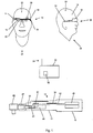
- zeigt in einer Prinzipskizze ein erfindunggemäßes Drehmomentwerkzeug.
- Fig. 2
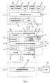
- zeigt als Blockdiagram den schematischen Aufbau eines Anzeigensystems.
- In
Fig. 1 wird mit 10 ein Anzeigensystem für ein erfindungsgemäßes Drehmomentwerkzeug 12 bezeichnet. Das Drehmomentwerkzeug 12 weist ein Gehäuse 13 mit einem Griff 15 an einem Ende auf. Das Anzeigensystem 10 enthält einen Projektor 14 und eine Projektionsfläche 16. Die Projektionsfläche 16 ist an einem brillenartigen Gestell bzw. Halterung 18 befestigt und kann so von einem Nutzer 20, wie eine Brille, getragen werden. Die Projektionsfläche 16 besteht aus einem teilweise reflektierendem und teilweise durchsichtigem Glas bzw. Kunststoff. Die Projektionsfläche 16 ist dabei vor wenigstens einem Auge 22 des Nutzers 20 angeordnet. Der Kopf des Nutzers 20 wird hier schematisch einmal von Vorne 24 und einmal von einer Seite 26 dargestellt. Das brillenartige Gestell 18 wird wie eine Brille getragen und hat einen Empfangsgerät 28, um Daten bzw. Informationen des Drehmomentwerkzeugs 12 über beispielsweise über Funk zu empfangen. Mittels Kamera 29 kann die Aktion des Nutzers mit dem Drehmomentwerkzeug 12 überwacht werden. Hierdurch lässt sich die genaue Position des Drehmomentwerkzeugs 12 ermitteln. Alternativ kann über Sensoren 81, welche Bestandteile der Steuerelektronik 42 sind, innerhalb des Drehmomentwerkzeugs 12 die Lage im Raum bestimmt werden. Außerdem ist es möglich eine Schraubverbindung auf dem Anzeigensystem 10 darzustellen und zu kennzeichnen. Ein Anwender erhält somit gegebenenfalls einen Arbeitsplan in dem Anzeigensystem 10. Dadurch lässt sich das Einhalten einer korrekten Reihenfolge beim Anziehen von Mehrschraubenverbindungen sicherstellen. - Die Daten bzw. Informationen des Drehmomentwerkzeugs 12, werden hierzu von einer separaten prozessorgesteuerten Datenverarbeitungsanlage 30 aufbereitet und übertragen. Die Datenverarbeitungsanlage 30 und das Drehmomentwerkzeug 12 sind mit einer Übertragungsvorrichtung 31 ausgerüstet. Die Datenverarbeitungsanlage 30 verfügt dazu über eine Sende- und Empfangseinrichtung 32. Hierüber empfängt die separate Datenverarbeitungsanlage 30 die Daten bzw. Informationen des Drehmomentwerkzeugs 12. Das Drehmomentwerkzeug 12 verfügt über eine entsprechende Sende- und Empfangseinrichtung 34. Anstelle von Funkverbindungen sind auch andere Übertragungsmittel zur Übertragung der Daten möglich, wie z.B. Kabel oder Infrarot. Üblicherweise erfolgt die Übertragung digital.
- Der Projektor 14 ist derartig an dem brillenartigen Gestell 18 befestigt, dass die Daten bzw. Informationen auf die Projektionsfläche 16 projiziert werden. Die Projektionsfläche 16 ist einerseits für den Nutzer 20 durchsichtig, reflektiert aber auf der anderen Seite die darauf projizierten Daten. Das jeweilig abzubildende Bild der Daten wird dabei über eine Mikrooptik-Anordnung auf die Projektionsfläche 16 projiziert. Der Projektor 14 weist daher einen hier nicht sichtbaren Darstellungsgenerator, wie eine LED-Anzeige, auf. Eine Lichtquelle, durchstrahlt diese LED-Anzeige und bildet die Information über die auf der Mikrooptik-Anordnung auf die Projektionsfläche 16 ab.
- Eine Alternative zu den getrennten Bestandteilen Projektionsfläche 16 und Projektor 14 besteht darin, diese als Einheit auszubilden. Die Projektionsfläche 16 ist gleichzeitig auch der Projektor 14, der angesteuert wird. Die Projektionsfläche 16 besteht dabei aus einer durchsichtigen LED-Anzeige, die geeignete angesteuert, als gleichzeitig als Projektor 14 dient. Die Bereiche, zur Darstellung werden dann angesteuert, so dass der Nutzer 20 bzw. ein Betrachter die aufbereiteten Daten sehen kann.
- Das Drehmomentwerkzeug 12 beinhaltet ein Verbindungsglied 37, in welches Einsteckwerkzeuge 82 eingesetzt werden können, mit einem Messkopfstück 38. Das Messkopfstück 38 weist Sensoren 40 auf, um ein Drehmoment und gegebenenfalls einen Winkel zu erfassen. Das Drehmomentwerkzeug 12 verfügt über eine Steuerelektronik 42 und einen mechanischen Auslösemechanismus 44. Der Auslösemechanismus 44 löst aus und signalisiert damit, dass ein bestimmtes voreingestelltes Drehmoment erreicht ist. Die Steuerelektronik 42 wird von einer Energieversorgung 46 gespeist. Die Energieversorgung 46 kann aus einem Netzkabel bestehen. Üblicherweise wird aber ein Akkumulator eingesetzt werden, um ausreichende Betätigungsfreiheit zu haben.
- In
Fig. 2 wird als Blockdiagram der schematische Aufbau des Anzeigensystems 10 für das Drehmomentwerkzeug 12 dargestellt. Ein mittlerer Block 48 umfasst das Drehmomentwerkzeug 12 mit der Steuerelektronik 42. Das Drehmomentwerkzeug 12 verfügt über einen digitalen Signalprozessor 50, auch abgekürzt DSP genannt. Ferner ist eine Eingabe 52 zur Steuerung des Drehmomentwerkzeugs 12 vorgesehen. Diese kann einerseits als Tastatur oder auch als Spracheingabe ausgebildet sein. In dem Block 48 ist ferner ein Auslösemechanismus 44 des Drehmomentwerkzeugs 12 dargestellt. Über eine Schnittstelle 56 können bidirektional zum Drehmomentwerkzeug 12 Daten übermittelt werden. Mit 58 werden eine Messsensorik für das Drehmoment und mit 60 eine Winkelmesssensorik des Drehmomentwerkzeugs 12 bezeichnet. Die Messsensorik 58 für das Drehmoment und die Winkelmesssensorik 60 enthaltend die Sensoren 40. Die Energieversorgung 46, welche üblicherweise als Batterie oder Akkumulator ausgebildet ist, liefert dem Drehmomentwerkzeug 12 die elektrische Energie um dessen elektrischen Komponenten zu betreiben. Das Drehmomentwerkzeug 12 verfügt ferner über eine Sende- bzw. Empfangseinrichtung 34 mit der Daten über Funk ausgetauscht werden können. Die Daten werden dabei bspw. direkt zwischen dem Anzeigensystem 10 oder mit der Datenverarbeitungsanlage 30 ausgetauscht. Sowohl die Datenverarbeitungsanlage 30, als auch das Anzeigensystem 10 sind als Blockdiagram 63, 64 dargestellt. - Die Datenverarbeitungsanlage 30 ist mit einer externen Steuerelektronik 68 verbunden. Die Steuerelektronik 68 dient dazu, aufgrund der Informationen in der Datenverarbeitungsanlage 30 das Drehmomentwerkzeug 12 zu steuern. Hier können beispielsweise die zu verwendenden Drehmomente übertragen werden. Die Übertragung der Daten zwischen den einzelnen Komponenten kann kabellos über Funk bzw. Infrarot oder über ein Datenkabel erfolgen.
- Das Anzeigensystem 10 ist ebenfalls als Blockdiagramm 64 dargestellt und enthält eine Steuerelektronik 70. Das Anzeigensystem 10 ist als Head-up-Display - HuD - ausgebildet. Das Anzeigensystem 10 verfügt ferner über eine Energieversorgung 72, um die elektrischen Komponenten mit ausreichender elektrischer Spannung zu versorgen. Das Anzeigensystem 10 enthält eine Darstellungsvorrichtung 74. In dem die Darstellungsvorrichtung 74 besteht aus einer Optikanordnung 76, dem Projektor 14 und der Projektionsfläche 16. Dabei können, wie bereits oben geschildert, der Projektor 14 und die Projektionsfläche 16 eine Einheit bilden. Üblicherweise kommt hier eine LED-Anzeige zum Einsatz. Das Head-up-Display enthält ein Mikrofon 78, um das Drehmomentwerkzeug 12 zu steuern bzw. um Daten aus der Datenverarbeitungsanlage 30 über Sprachsteuerung abzurufen. Weiterhin ist ein Lautsprecher 80 vorgesehen, über welchen akustisch signalisiert werden kann, wann ein Drehmoment erreicht worden ist. Auch andere Informationen können über Sprachausgabe oder verschiedenartige Töne oder Tonsequenzen mittels des Lautsprechers 80 ausgegeben werden. Der Datenaustausch erfolgt über die Sende- und Empfangseinrichtung 32 des Head-up-Displays.
Claims (4)
- Drehmomentwerkzeug (12) mit einem Anzeigensystem (10), welches zum Messen und/oder Ausbringen eines Drehmoments vorgesehen ist, enthaltenda) ein Gehäuse (13) mit einem Griff (15) am einen Ende, wobei eine Messeinrichtung (40, 58) zum Erfassen des Drehmoments in dem Gehäuse (13) angeordnet ist,b) ein Verbindungsglied (37) an dem anderen Ende des Gehäuses (13), welches das Drehmoment zu einem Werkstück überträgt,c) eine prozessorgesteuerte Steuereinrichtung (42, 50) zur digitalen Verarbeitung der eingestellten und/oder gemessenen Daten undd) eine Anzeige (16), welche mit der Steuereinrichtung (42, 50) kooperiert und graphische Anzeigeninhalte und/oder Daten, wie das jeweils anliegende bzw. eingestellte Drehmoment anzeigt, wobeie) eine Übertragungs- (28, 34) und eine als separate Darstellungsvorrichtung (74) zur Übertragung und Darstellung der graphischen Anzeigeninhalte und/oder der Daten vorgesehen ist,
dadurch gekennzeichnet, dassf) die Darstellungsvorrichtung (74) als Head-up- Display ausgebildet ist, welche aus einer Projektionsfläche (16) gebildet wird, in die die Anzeige mittels Projektor (14) projiziert wird, wobeig) die Projektionsfläche (16) an einer brillenartigen Halterung (18) vorgesehen ist, welche die Anzeige mittels des Projektors (14) unmittelbar vor ein Auge eines Anwenders projiziert undh) eine Kamera (29) an dem Drehmomentwerkzeug (12) und/oder der brillenartigen Halterung (18) vorgesehen ist, welche das Werkstück erfasst und das Drehmomentwerkzeug (12) dafür ausgelegt ist, dass durch Bilderkennung das richtige Drehmoment aus einer Datenbank zur automatischen Einstellung des Drehmomentwerkzeugs (12) abgefragt wird. - Drehmomentwerkzeug (12) mit einem Anzeigensystem (10), welches zum Messen und/oder Ausbringen eines Drehmoments vorgesehen ist, nach Anspruch 1, dadurch gekennzeichnet, dass die Übertragungsvorrichtung (31) als Funkverbindung, Infrarotverbindung und/oder als Kabelverbindung zwischen Drehmomentwerkzeug (12) und der separaten Darstellmigsvorrichtung (74) ausgebildet ist.
- Drehmomentwerkzeug (12) mit einem Anzeigensystem (10), welches zum Messen und/oder Ausbringen eines Drehmoments vorgesehen ist, nach einem der Ansprüche 1 oder 2, dadurch gekennzeichnet, dass die separate Darstellungsvorrichtung (74) als LED-Anzeige ausgebildet ist.
- Drehmomentwerkzeug (12) mit einem Anzeigensystem (10), welches zum Messen und/oder Ausbringen eines Drehmoments vorgesehen ist, nach einem der Ansprüche 1 bis 3, dadurch gekennzeichnet, dass das Drehmomentwerkzeug (12) eine Sprachsteuerung (78) und/oder einen akustischen Signalgeber (80) aufweist.
Applications Claiming Priority (1)
| Application Number | Priority Date | Filing Date | Title |
|---|---|---|---|
| DE202012104427U DE202012104427U1 (de) | 2012-11-16 | 2012-11-16 | Anzeigensystem für Drehmomentwerkzeuge |
Publications (3)
| Publication Number | Publication Date |
|---|---|
| EP2732922A2 EP2732922A2 (de) | 2014-05-21 |
| EP2732922A3 EP2732922A3 (de) | 2018-01-24 |
| EP2732922B1 true EP2732922B1 (de) | 2019-12-25 |
Family
ID=47426311
Family Applications (1)
| Application Number | Title | Priority Date | Filing Date |
|---|---|---|---|
| EP13005052.9A Active EP2732922B1 (de) | 2012-11-16 | 2013-10-23 | Drehmomentwerkzeug mit Anzeigensystem |
Country Status (3)
| Country | Link |
|---|---|
| US (1) | US9229232B2 (de) |
| EP (1) | EP2732922B1 (de) |
| DE (1) | DE202012104427U1 (de) |
Cited By (2)
| Publication number | Priority date | Publication date | Assignee | Title |
|---|---|---|---|---|
| EP4360808A1 (de) * | 2022-10-28 | 2024-05-01 | TKR Spezialwerkzeuge GmbH | Verfahren zur verwendung einer handhaltbaren zug- und druckvorrichtung zur reparatur von kraftfahrzeugbauteilen |
| EP4171866A4 (de) * | 2020-07-24 | 2024-08-21 | Schneider Electric USA, Inc. | Verwaltung von elektrischen geräten |
Families Citing this family (7)
| Publication number | Priority date | Publication date | Assignee | Title |
|---|---|---|---|---|
| JP5445796B2 (ja) * | 2012-01-25 | 2014-03-19 | 本田技研工業株式会社 | トルクレンチ |
| DE102013203553B3 (de) | 2013-03-01 | 2014-07-17 | Novopress Gmbh Pressen Und Presswerkzeuge & Co. Kg | Handgeführtes Pressgerät |
| DE102014019441B4 (de) | 2014-12-22 | 2021-09-23 | Audi Ag | Verfahren zum Montieren wenigstens eines Bauteils |
| JP6895630B2 (ja) * | 2018-07-03 | 2021-06-30 | パナソニックIpマネジメント株式会社 | 制御装置 |
| GB2579661A (en) | 2018-12-11 | 2020-07-01 | Tentec Ltd | Hydraulic tensioning apparatus |
| US11602810B2 (en) * | 2019-01-29 | 2023-03-14 | Jörg Hohmann | Method for documented tightening and re-tightening of a screw connection |
| JP7266451B2 (ja) | 2019-04-19 | 2023-04-28 | 株式会社ディスコ | ドライバー |
Citations (1)
| Publication number | Priority date | Publication date | Assignee | Title |
|---|---|---|---|---|
| WO2011028362A1 (en) * | 2009-09-02 | 2011-03-10 | The Boeing Company | Intelligent fastener system |
Family Cites Families (15)
| Publication number | Priority date | Publication date | Assignee | Title |
|---|---|---|---|---|
| DE10147045B4 (de) * | 2001-09-25 | 2005-03-17 | Dräger Safety AG & Co. KGaA | Datenkommumikationssystem für Masken- oder Helmträger |
| DE102005033323A1 (de) * | 2005-07-16 | 2007-01-18 | Bosch Rexroth Aktiengesellschaft | Werkzeug, insbesondere Schraubwerkzeug |
| US8782878B2 (en) * | 2005-09-28 | 2014-07-22 | Nikon Metrology Nv | Fastener automation system |
| CN101632033B (zh) * | 2007-01-12 | 2013-07-31 | 寇平公司 | 头戴式单眼显示装置 |
| DE202007002793U1 (de) * | 2007-02-22 | 2007-05-10 | Eduard Wille Gmbh & Co. Kg | Winkelmesseinrichtung |
| US20080252726A1 (en) * | 2007-04-10 | 2008-10-16 | Eastway Fair Company Limited | Video aid system |
| US20080319570A1 (en) * | 2007-06-25 | 2008-12-25 | Van Schoiack Michael M | System and method for fastener installation |
| DE202007018043U1 (de) | 2007-12-19 | 2008-03-13 | Hsieh, Chih-Ching | Steckschlüssel mit einem Drehkraftanzeiger |
| DE202008005705U1 (de) | 2008-04-24 | 2008-09-18 | Lin, Heiao-Feng, Taiping City | Drehmomentschlüssel mit digitaler Anzeige |
| DE202008018265U1 (de) * | 2008-07-24 | 2012-06-26 | Alexander Kipfelsberger | Vorrichtung mit einem Schraubwerkzeug mit elektronischer Drehmomentbegrenzung |
| DE202009002124U1 (de) | 2009-02-13 | 2009-04-23 | Hazet-Werk Hermann Zerver Gmbh & Co. Kg | Drehmomentschlüssel |
| JP5071508B2 (ja) | 2010-03-30 | 2012-11-14 | 株式会社デンソー | 車両用ヘッドアップディスプレイ装置 |
| TWM392713U (en) * | 2010-07-12 | 2010-11-21 | Legend Lifestyle Products Corp | Wireless torque wrench with angle correction feature |
| JP2012179935A (ja) | 2011-02-28 | 2012-09-20 | Jvc Kenwood Corp | 車両用表示装置 |
| US9666090B2 (en) * | 2011-11-29 | 2017-05-30 | Trimble Inc. | Reference based positioning of handheld tools |
-
2012
- 2012-11-16 DE DE202012104427U patent/DE202012104427U1/de not_active Expired - Lifetime
-
2013
- 2013-10-23 EP EP13005052.9A patent/EP2732922B1/de active Active
- 2013-11-15 US US14/081,051 patent/US9229232B2/en active Active
Patent Citations (1)
| Publication number | Priority date | Publication date | Assignee | Title |
|---|---|---|---|---|
| WO2011028362A1 (en) * | 2009-09-02 | 2011-03-10 | The Boeing Company | Intelligent fastener system |
Cited By (2)
| Publication number | Priority date | Publication date | Assignee | Title |
|---|---|---|---|---|
| EP4171866A4 (de) * | 2020-07-24 | 2024-08-21 | Schneider Electric USA, Inc. | Verwaltung von elektrischen geräten |
| EP4360808A1 (de) * | 2022-10-28 | 2024-05-01 | TKR Spezialwerkzeuge GmbH | Verfahren zur verwendung einer handhaltbaren zug- und druckvorrichtung zur reparatur von kraftfahrzeugbauteilen |
Also Published As
| Publication number | Publication date |
|---|---|
| DE202012104427U1 (de) | 2012-11-22 |
| US20140139406A1 (en) | 2014-05-22 |
| EP2732922A3 (de) | 2018-01-24 |
| EP2732922A2 (de) | 2014-05-21 |
| US9229232B2 (en) | 2016-01-05 |
Similar Documents
| Publication | Publication Date | Title |
|---|---|---|
| EP2732922A2 (de) | Anzeigensystem für Drehmomentwerkzeuge | |
| DE102013219376B4 (de) | Anzeigevorrichtung für ein Fahrzeug | |
| DE112015001200T5 (de) | Lichtemittierende Fahrzeug-Anzeigevorrichtung und Fahrzeug-Anzeigesystem | |
| EP3658976B1 (de) | Verfahren zum bereitstellen einer anzeige in einem kraftfahrzeug, sowie kraftfahrzeug | |
| EP2029073B1 (de) | Gesichts- und blendschutzvorrichtung für personen in arbeitsbereichen mit gefährlicher, schädlicher oder störender strahlung, insbesondere für schweisser | |
| DE112016003357B4 (de) | Anzeigevorrichtung vom Projektionstyp, Projektionsanzeigeverfahren und Projektions-Anzeigeprogramm | |
| US9811954B2 (en) | Near-to-eye display systems and methods for verifying aircraft components | |
| DE102007029602A1 (de) | Verfahren und Vorrichtung zum Bedienen einer in einem Fahrzeug befindlichen Einheit | |
| EP3012785B1 (de) | Verfahren sowie auswertegerät zur auswertung von signalen einer led-zustandsanzeige | |
| DE102007049710A1 (de) | Visuelles Auslösen von Vorgängen in einem Kraftfahrzeug | |
| JP6174451B2 (ja) | 電動ドライバ | |
| DE102008055186B4 (de) | Projektionsanzeigevorrichtung für Fahrzeuge | |
| EP4422905B1 (de) | Verfahren und vorrichtung zum bestimmen einer einbaupose einer fahrzeugfesten inertialsensorik in einem kraftfahrzeug | |
| EP1580588A1 (de) | Vorrichtung zur visuellen Darstellung einer Information | |
| DE112018000055B4 (de) | Rückspiegel mit der Funktion zum Anzeigen einer Armaturentafel sowie dessen Steuersystem | |
| CN105987717B (zh) | 驾驶员视觉传感器性能测试系统 | |
| DE102017209908A1 (de) | Kamerabasiertes Fahrerassistenzsystem sowie Verfahren zur Ansteuerung eines solchen | |
| DE102014214767B4 (de) | Anzeigeeinrichtung für ein Kraftfahrzeug, insbesondere Head-up-Display und Verfahren zur Steuerung einer Anzeigeeinrichtung | |
| DE202016002243U1 (de) | Schweisshelm mit Head-Up-Display | |
| CN101878130A (zh) | 用于监控显示装置的监控装置 | |
| DE102021121476B3 (de) | Projektionsvorrichtung, Kraftfahrzeug mit einer Projektionsvorrichtung und Verfahren zum Anpassen eines Projektionsparameters | |
| DE202012101883U1 (de) | Anzeigegerät eines Fahrzeuges | |
| DE102014206625A1 (de) | Positionierung eines HMD im Fahrzeug | |
| DE102019207454B4 (de) | Augmented-Reality-System | |
| DE102017216845B3 (de) | Anzeigevorrichtung und Kraftfahrzeug zum Anzeigen eines Bilds mit einer Folie zum Anzeigen eines Bilds mit wenigstens einer weiteren elektrischen Komponente |
Legal Events
| Date | Code | Title | Description |
|---|---|---|---|
| PUAI | Public reference made under article 153(3) epc to a published international application that has entered the european phase |
Free format text: ORIGINAL CODE: 0009012 |
|
| 17P | Request for examination filed |
Effective date: 20131023 |
|
| AK | Designated contracting states |
Kind code of ref document: A2 Designated state(s): AL AT BE BG CH CY CZ DE DK EE ES FI FR GB GR HR HU IE IS IT LI LT LU LV MC MK MT NL NO PL PT RO RS SE SI SK SM TR |
|
| AX | Request for extension of the european patent |
Extension state: BA ME |
|
| RAP1 | Party data changed (applicant data changed or rights of an application transferred) |
Owner name: STAHLWILLE EDUARD WILLE GMBH & CO. KG |
|
| PUAL | Search report despatched |
Free format text: ORIGINAL CODE: 0009013 |
|
| AK | Designated contracting states |
Kind code of ref document: A3 Designated state(s): AL AT BE BG CH CY CZ DE DK EE ES FI FR GB GR HR HU IE IS IT LI LT LU LV MC MK MT NL NO PL PT RO RS SE SI SK SM TR |
|
| AX | Request for extension of the european patent |
Extension state: BA ME |
|
| RIC1 | Information provided on ipc code assigned before grant |
Ipc: B25B 23/142 20060101AFI20171220BHEP Ipc: G02B 27/01 20060101ALI20171220BHEP |
|
| STAA | Information on the status of an ep patent application or granted ep patent |
Free format text: STATUS: REQUEST FOR EXAMINATION WAS MADE |
|
| STAA | Information on the status of an ep patent application or granted ep patent |
Free format text: STATUS: EXAMINATION IS IN PROGRESS |
|
| R17P | Request for examination filed (corrected) |
Effective date: 20180717 |
|
| RBV | Designated contracting states (corrected) |
Designated state(s): AL AT BE BG CH CY CZ DE DK EE ES FI FR GB GR HR HU IE IS IT LI LT LU LV MC MK MT NL NO PL PT RO RS SE SI SK SM TR |
|
| 17Q | First examination report despatched |
Effective date: 20180816 |
|
| GRAP | Despatch of communication of intention to grant a patent |
Free format text: ORIGINAL CODE: EPIDOSNIGR1 |
|
| STAA | Information on the status of an ep patent application or granted ep patent |
Free format text: STATUS: GRANT OF PATENT IS INTENDED |
|
| INTG | Intention to grant announced |
Effective date: 20190725 |
|
| GRAS | Grant fee paid |
Free format text: ORIGINAL CODE: EPIDOSNIGR3 |
|
| GRAA | (expected) grant |
Free format text: ORIGINAL CODE: 0009210 |
|
| STAA | Information on the status of an ep patent application or granted ep patent |
Free format text: STATUS: THE PATENT HAS BEEN GRANTED |
|
| AK | Designated contracting states |
Kind code of ref document: B1 Designated state(s): AL AT BE BG CH CY CZ DE DK EE ES FI FR GB GR HR HU IE IS IT LI LT LU LV MC MK MT NL NO PL PT RO RS SE SI SK SM TR |
|
| REG | Reference to a national code |
Ref country code: GB Ref legal event code: FG4D Free format text: NOT ENGLISH |
|
| REG | Reference to a national code |
Ref country code: CH Ref legal event code: EP |
|
| REG | Reference to a national code |
Ref country code: AT Ref legal event code: REF Ref document number: 1216645 Country of ref document: AT Kind code of ref document: T Effective date: 20200115 |
|
| REG | Reference to a national code |
Ref country code: DE Ref legal event code: R096 Ref document number: 502013014097 Country of ref document: DE |
|
| REG | Reference to a national code |
Ref country code: IE Ref legal event code: FG4D Free format text: LANGUAGE OF EP DOCUMENT: GERMAN |
|
| REG | Reference to a national code |
Ref country code: NL Ref legal event code: MP Effective date: 20191225 |
|
| PG25 | Lapsed in a contracting state [announced via postgrant information from national office to epo] |
Ref country code: NO Free format text: LAPSE BECAUSE OF FAILURE TO SUBMIT A TRANSLATION OF THE DESCRIPTION OR TO PAY THE FEE WITHIN THE PRESCRIBED TIME-LIMIT Effective date: 20200325 Ref country code: BG Free format text: LAPSE BECAUSE OF FAILURE TO SUBMIT A TRANSLATION OF THE DESCRIPTION OR TO PAY THE FEE WITHIN THE PRESCRIBED TIME-LIMIT Effective date: 20200325 Ref country code: LT Free format text: LAPSE BECAUSE OF FAILURE TO SUBMIT A TRANSLATION OF THE DESCRIPTION OR TO PAY THE FEE WITHIN THE PRESCRIBED TIME-LIMIT Effective date: 20191225 Ref country code: FI Free format text: LAPSE BECAUSE OF FAILURE TO SUBMIT A TRANSLATION OF THE DESCRIPTION OR TO PAY THE FEE WITHIN THE PRESCRIBED TIME-LIMIT Effective date: 20191225 Ref country code: SE Free format text: LAPSE BECAUSE OF FAILURE TO SUBMIT A TRANSLATION OF THE DESCRIPTION OR TO PAY THE FEE WITHIN THE PRESCRIBED TIME-LIMIT Effective date: 20191225 Ref country code: LV Free format text: LAPSE BECAUSE OF FAILURE TO SUBMIT A TRANSLATION OF THE DESCRIPTION OR TO PAY THE FEE WITHIN THE PRESCRIBED TIME-LIMIT Effective date: 20191225 Ref country code: GR Free format text: LAPSE BECAUSE OF FAILURE TO SUBMIT A TRANSLATION OF THE DESCRIPTION OR TO PAY THE FEE WITHIN THE PRESCRIBED TIME-LIMIT Effective date: 20200326 |
|
| REG | Reference to a national code |
Ref country code: LT Ref legal event code: MG4D |
|
| PG25 | Lapsed in a contracting state [announced via postgrant information from national office to epo] |
Ref country code: RS Free format text: LAPSE BECAUSE OF FAILURE TO SUBMIT A TRANSLATION OF THE DESCRIPTION OR TO PAY THE FEE WITHIN THE PRESCRIBED TIME-LIMIT Effective date: 20191225 Ref country code: HR Free format text: LAPSE BECAUSE OF FAILURE TO SUBMIT A TRANSLATION OF THE DESCRIPTION OR TO PAY THE FEE WITHIN THE PRESCRIBED TIME-LIMIT Effective date: 20191225 |
|
| PG25 | Lapsed in a contracting state [announced via postgrant information from national office to epo] |
Ref country code: AL Free format text: LAPSE BECAUSE OF FAILURE TO SUBMIT A TRANSLATION OF THE DESCRIPTION OR TO PAY THE FEE WITHIN THE PRESCRIBED TIME-LIMIT Effective date: 20191225 |
|
| PG25 | Lapsed in a contracting state [announced via postgrant information from national office to epo] |
Ref country code: EE Free format text: LAPSE BECAUSE OF FAILURE TO SUBMIT A TRANSLATION OF THE DESCRIPTION OR TO PAY THE FEE WITHIN THE PRESCRIBED TIME-LIMIT Effective date: 20191225 Ref country code: RO Free format text: LAPSE BECAUSE OF FAILURE TO SUBMIT A TRANSLATION OF THE DESCRIPTION OR TO PAY THE FEE WITHIN THE PRESCRIBED TIME-LIMIT Effective date: 20191225 Ref country code: PT Free format text: LAPSE BECAUSE OF FAILURE TO SUBMIT A TRANSLATION OF THE DESCRIPTION OR TO PAY THE FEE WITHIN THE PRESCRIBED TIME-LIMIT Effective date: 20200520 Ref country code: NL Free format text: LAPSE BECAUSE OF FAILURE TO SUBMIT A TRANSLATION OF THE DESCRIPTION OR TO PAY THE FEE WITHIN THE PRESCRIBED TIME-LIMIT Effective date: 20191225 Ref country code: CZ Free format text: LAPSE BECAUSE OF FAILURE TO SUBMIT A TRANSLATION OF THE DESCRIPTION OR TO PAY THE FEE WITHIN THE PRESCRIBED TIME-LIMIT Effective date: 20191225 |
|
| PG25 | Lapsed in a contracting state [announced via postgrant information from national office to epo] |
Ref country code: SM Free format text: LAPSE BECAUSE OF FAILURE TO SUBMIT A TRANSLATION OF THE DESCRIPTION OR TO PAY THE FEE WITHIN THE PRESCRIBED TIME-LIMIT Effective date: 20191225 Ref country code: SK Free format text: LAPSE BECAUSE OF FAILURE TO SUBMIT A TRANSLATION OF THE DESCRIPTION OR TO PAY THE FEE WITHIN THE PRESCRIBED TIME-LIMIT Effective date: 20191225 Ref country code: IS Free format text: LAPSE BECAUSE OF FAILURE TO SUBMIT A TRANSLATION OF THE DESCRIPTION OR TO PAY THE FEE WITHIN THE PRESCRIBED TIME-LIMIT Effective date: 20200425 |
|
| REG | Reference to a national code |
Ref country code: DE Ref legal event code: R097 Ref document number: 502013014097 Country of ref document: DE |
|
| PG25 | Lapsed in a contracting state [announced via postgrant information from national office to epo] |
Ref country code: DK Free format text: LAPSE BECAUSE OF FAILURE TO SUBMIT A TRANSLATION OF THE DESCRIPTION OR TO PAY THE FEE WITHIN THE PRESCRIBED TIME-LIMIT Effective date: 20191225 Ref country code: ES Free format text: LAPSE BECAUSE OF FAILURE TO SUBMIT A TRANSLATION OF THE DESCRIPTION OR TO PAY THE FEE WITHIN THE PRESCRIBED TIME-LIMIT Effective date: 20191225 |
|
| PLBE | No opposition filed within time limit |
Free format text: ORIGINAL CODE: 0009261 |
|
| STAA | Information on the status of an ep patent application or granted ep patent |
Free format text: STATUS: NO OPPOSITION FILED WITHIN TIME LIMIT |
|
| PG25 | Lapsed in a contracting state [announced via postgrant information from national office to epo] |
Ref country code: SI Free format text: LAPSE BECAUSE OF FAILURE TO SUBMIT A TRANSLATION OF THE DESCRIPTION OR TO PAY THE FEE WITHIN THE PRESCRIBED TIME-LIMIT Effective date: 20191225 |
|
| 26N | No opposition filed |
Effective date: 20200928 |
|
| PG25 | Lapsed in a contracting state [announced via postgrant information from national office to epo] |
Ref country code: PL Free format text: LAPSE BECAUSE OF FAILURE TO SUBMIT A TRANSLATION OF THE DESCRIPTION OR TO PAY THE FEE WITHIN THE PRESCRIBED TIME-LIMIT Effective date: 20191225 |
|
| REG | Reference to a national code |
Ref country code: CH Ref legal event code: PL |
|
| PG25 | Lapsed in a contracting state [announced via postgrant information from national office to epo] |
Ref country code: MC Free format text: LAPSE BECAUSE OF FAILURE TO SUBMIT A TRANSLATION OF THE DESCRIPTION OR TO PAY THE FEE WITHIN THE PRESCRIBED TIME-LIMIT Effective date: 20191225 Ref country code: LU Free format text: LAPSE BECAUSE OF NON-PAYMENT OF DUE FEES Effective date: 20201023 |
|
| REG | Reference to a national code |
Ref country code: BE Ref legal event code: MM Effective date: 20201031 |
|
| PG25 | Lapsed in a contracting state [announced via postgrant information from national office to epo] |
Ref country code: CH Free format text: LAPSE BECAUSE OF NON-PAYMENT OF DUE FEES Effective date: 20201031 Ref country code: BE Free format text: LAPSE BECAUSE OF NON-PAYMENT OF DUE FEES Effective date: 20201031 Ref country code: LI Free format text: LAPSE BECAUSE OF NON-PAYMENT OF DUE FEES Effective date: 20201031 |
|
| PG25 | Lapsed in a contracting state [announced via postgrant information from national office to epo] |
Ref country code: IE Free format text: LAPSE BECAUSE OF NON-PAYMENT OF DUE FEES Effective date: 20201023 |
|
| REG | Reference to a national code |
Ref country code: AT Ref legal event code: MM01 Ref document number: 1216645 Country of ref document: AT Kind code of ref document: T Effective date: 20201023 |
|
| PG25 | Lapsed in a contracting state [announced via postgrant information from national office to epo] |
Ref country code: AT Free format text: LAPSE BECAUSE OF NON-PAYMENT OF DUE FEES Effective date: 20201023 |
|
| PG25 | Lapsed in a contracting state [announced via postgrant information from national office to epo] |
Ref country code: TR Free format text: LAPSE BECAUSE OF FAILURE TO SUBMIT A TRANSLATION OF THE DESCRIPTION OR TO PAY THE FEE WITHIN THE PRESCRIBED TIME-LIMIT Effective date: 20191225 Ref country code: MT Free format text: LAPSE BECAUSE OF FAILURE TO SUBMIT A TRANSLATION OF THE DESCRIPTION OR TO PAY THE FEE WITHIN THE PRESCRIBED TIME-LIMIT Effective date: 20191225 Ref country code: CY Free format text: LAPSE BECAUSE OF FAILURE TO SUBMIT A TRANSLATION OF THE DESCRIPTION OR TO PAY THE FEE WITHIN THE PRESCRIBED TIME-LIMIT Effective date: 20191225 |
|
| PG25 | Lapsed in a contracting state [announced via postgrant information from national office to epo] |
Ref country code: MK Free format text: LAPSE BECAUSE OF FAILURE TO SUBMIT A TRANSLATION OF THE DESCRIPTION OR TO PAY THE FEE WITHIN THE PRESCRIBED TIME-LIMIT Effective date: 20191225 |
|
| PGFP | Annual fee paid to national office [announced via postgrant information from national office to epo] |
Ref country code: DE Payment date: 20251027 Year of fee payment: 13 |
|
| PGFP | Annual fee paid to national office [announced via postgrant information from national office to epo] |
Ref country code: GB Payment date: 20251024 Year of fee payment: 13 |
|
| PGFP | Annual fee paid to national office [announced via postgrant information from national office to epo] |
Ref country code: IT Payment date: 20251031 Year of fee payment: 13 |
|
| PGFP | Annual fee paid to national office [announced via postgrant information from national office to epo] |
Ref country code: FR Payment date: 20251029 Year of fee payment: 13 |