EP2732086B1 - Device and method for clamping a weft thread - Google Patents
Device and method for clamping a weft thread Download PDFInfo
- Publication number
- EP2732086B1 EP2732086B1 EP12731447.4A EP12731447A EP2732086B1 EP 2732086 B1 EP2732086 B1 EP 2732086B1 EP 12731447 A EP12731447 A EP 12731447A EP 2732086 B1 EP2732086 B1 EP 2732086B1
- Authority
- EP
- European Patent Office
- Prior art keywords
- clamping element
- central
- outer clamping
- weft thread
- central clamping
- Prior art date
- Legal status (The legal status is an assumption and is not a legal conclusion. Google has not performed a legal analysis and makes no representation as to the accuracy of the status listed.)
- Active
Links
Images







Classifications
-
- D—TEXTILES; PAPER
- D03—WEAVING
- D03D—WOVEN FABRICS; METHODS OF WEAVING; LOOMS
- D03D47/00—Looms in which bulk supply of weft does not pass through shed, e.g. shuttleless looms, gripper shuttle looms, dummy shuttle looms
- D03D47/12—Looms in which bulk supply of weft does not pass through shed, e.g. shuttleless looms, gripper shuttle looms, dummy shuttle looms wherein single picks of weft thread are inserted, i.e. with shedding between each pick
- D03D47/125—Weft holding devices
-
- D—TEXTILES; PAPER
- D03—WEAVING
- D03D—WOVEN FABRICS; METHODS OF WEAVING; LOOMS
- D03D47/00—Looms in which bulk supply of weft does not pass through shed, e.g. shuttleless looms, gripper shuttle looms, dummy shuttle looms
- D03D47/34—Handling the weft between bulk storage and weft-inserting means
- D03D47/38—Weft pattern mechanisms
-
- D—TEXTILES; PAPER
- D03—WEAVING
- D03D—WOVEN FABRICS; METHODS OF WEAVING; LOOMS
- D03D49/00—Details or constructional features not specially adapted for looms of a particular type
- D03D49/70—Devices for cutting weft threads
Definitions
- the invention relates to a device and a method for clamping a weft thread in a weaving machine, more particularly in a rapier weaving machine.
- a weft thread positioned in the path of a gripper is gripped by the gripper and inserted into the shed.
- the inserted weft thread is cut off on the insertion side in order to allow a subsequent weft thread to be inserted. It is known to position a weft thread to be inserted in the path of the gripper by using a presenting element of a presenting device that is arranged on the weaving machine next to the shed, for example as described in EP 0 598 264 A1 .
- EP 0 644 286 A1 relates to an apparatus for presenting weft threads on a rapier weaving machine comprising a movably mounted weft thread clamping unit having at least three weft thread clamps which are spaced apart in the direction of movement of the clamping unit, a positioning device for moving each of the weft thread clamps into a reference plane, which positioning device comprises a stepping motor.
- DE 10 2008 027 131 A1 further describes to provide a device for cutting a weft thread comprising a first and a second blade moved relative to one another by means of a driving device comprising a pneumatic piston.
- a device for clamping a weft thread in a weaving machine comprising a central clamping element, a first outer clamping element and a second outer clamping element, wherein the central clamping element is forced in two opposite clamping directions towards an intermediate position, wherein the central clamping element being sandwiched between the first outer clamping element and the second outer clamping element, when the central clamping element is positioned in the intermediate position, wherein both the first outer clamping element and the second outer clamping element abut against the central clamping element in the intermediate position, the device comprises further a drive device adapted for displacing the central clamping element out of the intermediate position in two clamping directions, a first clamping direction to at least one first position and a second clamping direction to at least one second position, wherein in the first position the central clamping element is at a distance from the first outer clamping element and in the second position the central clamping element is at a distance from the second outer clamping element, where
- clamping device The device for clamping a weft thread is also referred to as clamping device.
- clamping direction is meant a movement direction wherein the clamping elements move during the opening or the closing of the clamps.
- the central clamping element makes contact with the first outer clamping element and with the second outer clamping element when the central clamping element is positioned in the intermediate position.
- the total height of the at least one abutment element arranged between the first and the second outer clamping element is defined as the distance between two abutment surfaces limiting a movement of the first and the second outer clamping element towards each other. If only one abutment element is provided, the total height equals the height of this abutment element.
- the at least one abutment element is centred with the central clamping element when the central clamping element is arranged in the intermediate position. In other embodiments, the at least one abutment element is a little off centre in one of the two clamping directions.
- the total height of the at least one abutment element is smaller than the height or the thickness of the central clamping element, in order to allow that both the first and the second outer clamping element abut against the central clamping element in an intermediate position. Because of that smaller height of the at least one abutment element a play is achieved between the clamping elements and the at least one abutment element which is advantageous to keep the clamps in the intermediate position closed, in other words against the central clamping element, what allows to always clamp a weft thread, even if the clamping elements due to their sudden movements move or vibrate a bit up and down, more in particular vibrate after the contacting of a clamping element with the central clamping element, this means after the closing of a clamp. In this case all clamping elements can vibrate together over that play without one of the clamps opening and releasing a weft thread.
- the piston may adopt a first upper piston position when only the lower chamber of the pneumatic cylinder is pressurized, adopt a second lower piston position when only the upper chamber of the pneumatic cylinder is pressurized, and adopt a third intermediate piston position when the loads applied on the piston are balanced.
- the loads applied on the piston are balanced when none of the two chambers is pressurized.
- the central clamping element will adopt an intermediate position when no pressurized fluid is supplied.
- the intermediate position may be adopted when the both chambers are pressurized.
- the pneumatic cylinder comprises at least a spring, preferably two springs, loading the piston.
- the springs are adapted to hold the piston in the third intermediate piston position, wherein also the central clamping element is in its intermediate position.
- the loads applied by the two springs are balanced.
- the load applied by this spring in the third intermediate position for example is almost negligible.
- the clamping device comprises a first force element forcing the first outer clamping element towards the central clamping element, a second force element forcing the second outer clamping element towards the central clamping element, and at least one abutment element for limiting a displacement of the first and the second outer clamping element caused by the displacement of the central clamping element and a force applied by the first and the second force element on the first and the second outer clamping element, respectively.
- the first and the second force element in preferred embodiments are realized as spring elements.
- the first and the second force elements assume the functions of the springs of the pneumatic cylinder, wherein the springs of the pneumatic cylinder may be omitted.
- the force elements are co-operating with the springs of the pneumatic cylinder, wherein the loads applied by the force elements are preferably chosen smaller than the forces applied by the springs of the pneumatic cylinder.
- the first outer clamping element and/or the second outer clamping element are formed as a plate being fixed to a guiding shaft.
- the length of the guiding shafts is chosen in an embodiment in order to limit a movement of the outer clamping elements.
- the guiding shafts may therefore assume the function of the at least one abutment element.
- the guiding shafts co-operate with an abutment element provided between the outer clamping elements.
- the plates provide a light-weight solution.
- guiding shafts for the central clamping element, the first outer clamping element and second outer clamping element are coaxially arranged.
- the piston rod of the pneumatic cylinder functions as a guiding shaft for the central clamping element.
- the piston rod extends through the central clamping element, the first outer clamping element and the second outer clamping element.
- the central clamping element is arranged in a fixed position on the piston rod or is formed integrally with the piston rod.
- the first outer clamping element and the second outer clamping element are provided with feed-through openings for the piston rod.
- the guiding shafts for the first outer clamping element and for the second outer clamping element are formed as tubular shaped shafts arranged concentrically around the piston rod.
- a receiving section of the clamps formed by the central clamping element and the outer clamping elements are arranged approximately perpendicular to the weft thread when the weft thread is taken up by the associated clamp, because such an arrangement is advantageous for catching the weft thread.
- the distal end of the central clamping element that is directed towards a weft thread to be clamped forms an intake funnel with the distal end of the first outer clamping element and/or with the distal end of the second outer clamping element. This allows the weft thread to be taken up by the clamping device more easily.
- the clamping device can be arranged in a fixed position on the weaving machine.
- the device also comprises an abutment which limits the movement of the first outer clamping element in the second position and/or an abutment which limits the movement of the second outer clamping element in the first position. This limits vibrations that may arise after reaching the first or second position of the clamping elements, whereby it is avoided that a clamped weft thread is laying free in the clamp, this means is let free, shortly after reaching the first or second position.
- the clamping device is arranged in a module.
- the module allows an easy and reliable positioning on the weaving machine.
- the device is arranged in a fixed position on the weaving machine, this means in a fixed position with respect to a gripper path, a cloth line and a cloth edge.
- the fixed position is adjustable and may be chosen suitably with respect to the gripper path, the cloth line and the cloth edge of the woven cloth in order to clamp the inserted weft threads.
- the module further comprises at least one thread guiding element arranged upstream of the clamping device according to the invention in insertion direction.
- insertion direction is meant the direction of the gripper movement.
- the thread guiding element is arranged close to the gripper path in the vicinity of an area where the weft thread is taken up by the gripper. Integrating a guiding element in a module allows a reliable and simple assembly.
- the module comprises in an alternative or in addition at least one cutting device arranged downstream of the central clamping element in weft direction.
- a cutting device By providing a cutting device in a position adjacent to the cloth edge between the clamping device according to the invention and the cloth edge, inserted weft threads may be cut essentially to the same length and the weft thread ends protruding beyond the cloth edge may be kept to a minimum.
- the cutting device comprises a stationary jaw and a movable jaw, for example of the type shown in WO 2009/007076 A1 . The content of which is hereby incorporated by reference.
- the module comprising the clamping device and the cutting device is arranged next to the cloth edge, wherein the weft thread ends may be cut to a length of less than 10mm, for example to lengths between 4mm and 8mm.
- the cutting device and the clamping device may be arranged in a certain position and also mutually arranged at a certain settable distance from each other. This setting may be either in the insertion direction as in the warp direction.
- the cutting device and the clamping device may herein be arranged as a unit or separately in a certain position.
- the module is arranged to be moveable towards and away from a gripper in a plane approximately parallel or parallel to the cloth edge of the woven cloth.
- the module is arranged at least partly on a rotatable shaft to be moved towards and away from the gripper.
- the arrangement allows to bring the device close to the gripper path in the vicinity of an area where a weft thread is taken up by the gripper, because such an arrangement is advantageous for keeping a weft thread end protruding beyond the thread clamp in the gripper short, which allows to keep the thread end protruding beyond the cloth edge at the opposite side of the shed under control, this means short.
- the object is further solved by a method for clamping a weft thread in a weaving machine, more particularly in a rapier weaving machine, wherein an inserted weft thread is introduced in a device for clamping a weft thread arranged next to a cloth edge of the woven cloth, wherein the device comprises a central clamping element, a first outer clamping element and a second outer clamping element, wherein the central clamping element being forced in two opposite clamping directions to an intermediate position, wherein the central clamping element being sandwiched between the first outer clamping element and the second outer clamping element, when the central clamping element is positioned in the intermediate position, wherein the device further comprises a drive device adapted for displacing the central clamping element from the intermediate position in two clamping directions, a first clamping direction to at least one first position and a second clamping direction to at least one second position, wherein in the first position the central clamping element is at a distance from the first outer clamping element and in the second position the central clamping element is at
- An actuating by supplying compressed air allows the central clamping element to be displaced with a high reliability and at high speeds.
- the drive device is a double acting pneumatic cylinder having a first chamber and a second chamber, wherein the first chamber is pressurized for moving the piston in the first position and a second chamber is pressurized for moving the piston in the second position.
- the weft thread is clamped by the clamping device before the cutting device cuts the weft thread.
- the weft thread is released by the clamping device.
- the gripper takes up a weft thread and the weft thread taken up by the gripper is pulled out of a clamp of the clamping device while the clamp is still closed. The clamp only opens afterwards by supplying compressed air.
- Weft threads 6 are schematically shown in Fig. 2 .
- a weft thread 6 runs from the presenting device 2, via the gripper 3, the thread guiding element 4, the device 1 for clamping a weft thread 6, and the cutting device 5 to the cloth edge 8 and the woven cloth 9 with the cloth line 7.
- the cloth 9 can in this case support on a cloth support not shown.
- the cloth edge 8 is a side edge of the cloth 9 that extends in warp direction
- the cloth line 7 is the beat-up edge of the cloth 9 that extends in weft direction.
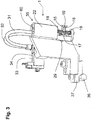
- the device 1 for clamping a weft thread is described in more detail with reference to Figures 3 to 8 , showing the device 1 for clamping a weft thread and parts of the device 1 for clamping a weft thread in detail.
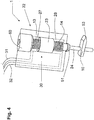
- the device 1 comprises a central clamping element 10 shown in more detail in Fig. 4 , a first outer clamping element 15, and a second outer clamping element 16, as shown in Fig. 5 .
- the central clamping element 10 is movable supported, this means is forced in two opposite clamping directions to an intermediate position P shown in amongst others Fig. 6 .
- the central clamping element 10 is sandwiched between the first outer clamping element 15 and the second outer clamping element 16 and makes contact with the first outer clamping element 15 and the second outer clamping element 16 when positioned in the intermediate position P.
- both the first clamp 20 formed by the central clamping element 10 and the first outer clamping element 15 and the second clamp 21 formed by the central clamping element 10 and the second outer clamping element 16 are closed in the intermediate position P in order to clamp a weft thread, each.
- two force elements 18, 19 designed as springs are provided in order to force the first outer clamping element 15 towards the central clamping element 10, and the second outer clamping element 16 towards the central clamping element 10, respectively.
- the drive device 22 is a pneumatic double acting cylinder 30 comprising a piston 23, which piston 23 is directly coupled to the central clamping element 10 for a transmission of motion via the piston rod 24 of the piston 23.
- the central clamping element 10, the piston rod 24 and the piston 23 are mechanically coupled or manufactured as an assembly, so that the central clamping element 10 is moved directly by the piston 23.
- the piston 23 is herein balanced by two springs 13, 14 each provided in a chamber 27 or 28, also named pressure chamber, which springs 13, 14 force the piston 23 in a central position as long as no compressed air is fed. In consequence, without a pressure supply, the central clamping element 10 is held in the intermediate position.
- the intermediate position is obtained by feeding compressed air to both chambers 27, 28.
- the outer clamping elements 15 and 16 are movable arranged and the two force elements 18, 19 ensure that the first clamp 20 and the second clamp 21 initially remain closed upon displacement of the central clamping element 10.
- the device 1 further comprises an abutment element 17 arranged between the first outer clamping element 15 and the second outer clamping element 16 in the movement path of the outer clamping elements 15, 16, wherein a height H1 of the central clamping element 10 is larger than a height H2 of the abutment element 17, as may be seen in Figures 5 and 6 .
- the depicted abutment element 17 is fork shaped, wherein the two tips of the fork shaped element surround the central clamping element 10 without limiting a movement of the central clamping element 10 in the two clamping directions K and L.
- the two tips of the abutment element 17 may limit the movement of the clamping elements 15 and 16 by abutting against broadenings provided at the clamping elements 15 and 16.
- two abutment elements are provided, for example each of which formed by a fork shaped element. These two abutment elements are arranged at a distance from one another and can each co-operate with an associated outer clamping element 15 or 16, and in this way function together as the one piece clamping element 17.
- the force element 18 loads the first outer clamping element 15 in order to follow the movement of the central clamping element 10 until the first outer clamping element 15 abuts against the abutment element 17 so that the first clamp 20 opens, while the second clamp 21 remains closed.
- the force element 19 loads the second outer clamping element 16 in order to follow the movement of the central clamping element 10 until the second outer clamping element 16 abuts against the abutment element 17 so that the second clamp 21 opens, while the first clamp 20 remains closed.
- the abutment element 17 and the central clamping element 10 are aligned in an intermediate position, wherein through a slit 65 a positioning screw 29 is provided for aligning the abutment element 17 in relation to the central clamping element 10 in the intermediate position.
- a positioning screw 29 is provided for aligning the abutment element 17 in relation to the central clamping element 10 in the intermediate position.
- an alien screw 60 is arranged rotatable in the housing 22.
- the drive device 22 is a pneumatic acting double cylinder 30 comprising a piston 23, arranged between two chambers 27 and 28, wherein a spring 13, 14 is provided in each chamber 27, 28. Compressed air is supplied to each of the two chambers 27, 28 via respective ducts 31, 32 with valves 33, 34 for interrupting the air supply.
- the force elements 18, 19 take over the function of the springs 13 and 14 and the springs 13, 14 may be omitted. In this case, a balancing of the force elements 18, 19 is to be ensured.
- the outer clamping elements 15, 16 are formed as plates that are fixed on guiding shafts 25, 26.
- the guiding shafts 25, 26 are of tubular shape and coaxially arranged with the piston rod 24, so that the guiding shafts 25, 26 surround the piston rod 24 and the piston rod 24 is displaceable inside the tubular shaped guiding shafts 25, 26.
- the tubular shaped guiding shafts 25, 26 allow that the outer clamping elements 15 and 16 move coaxially with the guiding shafts 25, 26, but independent of the piston rod 24.
- the length of the tubular shaped guiding shafts 25, 26 is further chosen so that the movement of the outer clamping elements 15, 16 is limited by additional abutments 51, 52.
- the abutment 51 forms part of a ring element 66 and limits the movement of the first clamping element 15 in the second position
- the abutment 52 forms part of a ring element 67 and limits the movement of the second clamping element 16 in the first position.
- the central clamping element 10 is provided with a distal end 53 shaped as a wedge shaped tip.
- the distal end 54 of the first outer clamping element 15 and the distal end 55 of the second outer clamping element 16 are each bent away from the central clamping element 10, more particularly bent in such a way that the distal ends 54, 55 each form an intake funnel 56, 57 with the distal end 53 of the central clamping element 10.
- the distal ends 53 and 54 form a receiving section 58 for the one weft thread, while the distal ends 53 and 55 form a receiving section 59 for the other weft thread.
- the device 1 is arranged in a module 35 and can be positioned with respect to the weaving machine using two positioning elements 36, 37.
- the module 35 for example, comprises also the thread guiding element 4 that is arranged in insertion direction N upstream of the central clamping element 10 of the device 1.
- the module 35 for example, also comprises the cutting device 5 that is arranged in insertion direction N downstream of the central clamping element 10 of the device 1.
- all aforementioned elements may be arranged separately at a settable distance from each other.
- the arm 38 is arranged on a rotatable shaft 41, which shaft 41 is driven via a rod 42, a coupling rod 43 and a lever 44 by the cams 48.
- the position of the coupling rod 43 on the lever 44 may be adjusted by using a bolt 45 arranged in a slot 46 provided on the lever 44 in order to set the moving course of the device 1.
- a spring 47 forces the lever 44 into contact with the cams 48.
- the drive axis 49 for the cams 48 is synchronised with the movement of the weaving machine, for example via a mechanical coupling or via a drive by an own controllable drive motor, in order to avoid that the device 1 according to the invention may come into contact with a reed 50 or with a sley 63 on which a reed can be fixed, shown in Fig. 2 .
- a pneumatic system and/or an electromagnetic system can be provided for moving the device 1 towards and away from the gripper 3.
- the valves 33, 34 for regulating the supply of compressed air via the ducts 31, 32 are fixedly arranged on the frame 40.
- the device 1 By moving the arm 38 in the rotation direction R, the device 1 according to the invention may be positioned towards or away from the gripper 3.
- the device 1 can be arranged close to the gripper 3 during the taking up of a weft thread by the gripper 3 and during the taking up of a weft thread by the device 1 be arranged away from the gripper 3 and almost be arranged in the elongation of the cloth line 7.
- a suction nozzle 64 may be arranged for catching and holding weft threads that are released unwanted from the device 1 for clamping a weft thread. This allows to still catch and keep such weft threads in the suction nozzle 64, so that these weft threads still can be taken up and inserted by the gripper 3 during a next insertion and subsequently be clamped again in the device 1 for clamping weft thread according to the invention.
- the device 1 is brought in such a position that the inserted weft thread can be taken up in an opened clamp 20 or 21 and subsequently be clamped by closing this clamp 20, 21.
- the device 1 is arranged so that during the taking up the weft thread extends almost perpendicular to the direction of the taking up of the weft thread in the clamp 20 or 21. Subsequently the clamped weft thread is cut off by the cutting device 5 between the device 1 and the cloth 9.
- a weft thread presented by the presenting device 2 is taken up by the gripper 3 and inserted in the shed, wherein this weft thread is pulled out of the device 1 by the gripper 3 while the associated clamp 20, 21 is preferably still closed and the weft thread is released by the device 1.
- the associated clamp 20 or 21 is opened afterwards in order to take up an inserted weft thread.
- the device 1 for clamping a weft thread is adapted to co-operate with two weft threads.
- the devices for clamping a weft thread are preferably each arranged on a movable frame, which thus allows to weave with more than two weft threads and more than two presenting devices for weft thread.
- two devices according to the invention are used which are arranged mirror symmetrical to each other.
- the cloth 9 can be bound by so-called leno-threads which are arranged approximately parallel to and next to the warp threads.
Landscapes
- Engineering & Computer Science (AREA)
- Textile Engineering (AREA)
- Looms (AREA)
Description
- The invention relates to a device and a method for clamping a weft thread in a weaving machine, more particularly in a rapier weaving machine.
- When weaving, a weft thread positioned in the path of a gripper is gripped by the gripper and inserted into the shed. The inserted weft thread is cut off on the insertion side in order to allow a subsequent weft thread to be inserted. It is known to position a weft thread to be inserted in the path of the gripper by using a presenting element of a presenting device that is arranged on the weaving machine next to the shed, for example as described in
EP 0 598 264 A1 - It is further known to provide a clamping device arranged between a weft presenting device and a weft thread cutter. For example,
EP 0 644 286 A1 -
EP 0 421 349 A1 -
DE 10 2008 027 131 A1 - It is the object of the invention to provide a device and a method for clamping an inserted weft thread that allows a reliable clamping of an inserted weft thread.
- This object is solved by a device for clamping a weft thread in a weaving machine, more particularly in a rapier weaving machine, the device comprising a central clamping element, a first outer clamping element and a second outer clamping element, wherein the central clamping element is forced in two opposite clamping directions towards an intermediate position, wherein the central clamping element being sandwiched between the first outer clamping element and the second outer clamping element, when the central clamping element is positioned in the intermediate position, wherein both the first outer clamping element and the second outer clamping element abut against the central clamping element in the intermediate position, the device comprises further a drive device adapted for displacing the central clamping element out of the intermediate position in two clamping directions, a first clamping direction to at least one first position and a second clamping direction to at least one second position, wherein in the first position the central clamping element is at a distance from the first outer clamping element and in the second position the central clamping element is at a distance from the second outer clamping element, wherein the drive device comprises a pneumatic cylinder with at least one piston, wherein the piston and/or a piston rod of the piston (23) is formed integrally with or is mechanically coupled to the central clamping element for a transmission of motion in the clamping directions, and wherein the device further comprises at least one abutment element arranged between the first outer clamping element and the second outer clamping element for limiting a movement of the first outer clamping element and the second outer clamping element towards each other, wherein a height of the central clamping element is larger than the total height of the at least one abutment element.
- The device for clamping a weft thread is also referred to as clamping device. In the context of the invention with clamping direction is meant a movement direction wherein the clamping elements move during the opening or the closing of the clamps.
- A pneumatic cylinder allows the central clamping element to be displaced with a high reliability and at high speeds. In an embodiment, the central clamping element is formed integrally with a piston and/or a piston rod. In other embodiments, the elements are formed as separate parts, which are mechanically coupled. The mechanical coupling in one embodiment is a releasable connection, for example using screw elements. In other embodiments, a permanent connection is chosen, for example by welding or gluing the elements together. When using a pneumatic cylinder, desired forces may be applied. The direct coupling of the central clamping element to the piston allows to achieve a light-weight device suitable for co-operating with a pneumatic cylinder. In this case the piston is directly coupled to the central clamping element for a transmission of movement in the clamping direction.
- Further, when providing a pneumatic cylinder, a compact structure may be obtained. In absence of weft thread, the central clamping element makes contact with the first outer clamping element and with the second outer clamping element when the central clamping element is positioned in the intermediate position.
- In the context of the invention, the total height of the at least one abutment element arranged between the first and the second outer clamping element is defined as the distance between two abutment surfaces limiting a movement of the first and the second outer clamping element towards each other. If only one abutment element is provided, the total height equals the height of this abutment element. In preferred embodiments, the at least one abutment element is centred with the central clamping element when the central clamping element is arranged in the intermediate position. In other embodiments, the at least one abutment element is a little off centre in one of the two clamping directions. In both cases, the total height of the at least one abutment element is smaller than the height or the thickness of the central clamping element, in order to allow that both the first and the second outer clamping element abut against the central clamping element in an intermediate position. Because of that smaller height of the at least one abutment element a play is achieved between the clamping elements and the at least one abutment element which is advantageous to keep the clamps in the intermediate position closed, in other words against the central clamping element, what allows to always clamp a weft thread, even if the clamping elements due to their sudden movements move or vibrate a bit up and down, more in particular vibrate after the contacting of a clamping element with the central clamping element, this means after the closing of a clamp. In this case all clamping elements can vibrate together over that play without one of the clamps opening and releasing a weft thread.
- According to an embodiment, the pneumatic cylinder is a double acting pneumatic cylinder, more particularly a double acting pneumatic cylinder which can be held in a first position, a second position and a third intermediate position. The piston of the pneumatic cylinder is moveable in the clamping direction. Providing a double acting pneumatic cylinder allows the piston to adopt three positions and, hence, also to couple the central clamping element directly to the piston to adopt three positions. In a preferred embodiment, the piston is arranged vertical or essentially vertical. With this arrangement, the piston may adopt a first upper piston position when only the lower chamber of the pneumatic cylinder is pressurized, adopt a second lower piston position when only the upper chamber of the pneumatic cylinder is pressurized, and adopt a third intermediate piston position when the loads applied on the piston are balanced. Preferably, the loads applied on the piston are balanced when none of the two chambers is pressurized. In this case, the central clamping element will adopt an intermediate position when no pressurized fluid is supplied. However, in other solutions, the intermediate position may be adopted when the both chambers are pressurized.
- In an embodiment, the pneumatic cylinder comprises at least a spring, preferably two springs, loading the piston. The springs are adapted to hold the piston in the third intermediate piston position, wherein also the central clamping element is in its intermediate position. When using two springs, in the third intermediate position the loads applied by the two springs are balanced. When using only one spring the load applied by this spring in the third intermediate position for example is almost negligible.
- In preferred embodiments, the clamping device comprises a first force element forcing the first outer clamping element towards the central clamping element, a second force element forcing the second outer clamping element towards the central clamping element, and at least one abutment element for limiting a displacement of the first and the second outer clamping element caused by the displacement of the central clamping element and a force applied by the first and the second force element on the first and the second outer clamping element, respectively. The first and the second force element in preferred embodiments are realized as spring elements. In an embodiment, the first and the second force elements assume the functions of the springs of the pneumatic cylinder, wherein the springs of the pneumatic cylinder may be omitted. In other embodiments, the force elements are co-operating with the springs of the pneumatic cylinder, wherein the loads applied by the force elements are preferably chosen smaller than the forces applied by the springs of the pneumatic cylinder.
- According to an embodiment, the first outer clamping element and/or the second outer clamping element are formed as a plate being fixed to a guiding shaft. The length of the guiding shafts is chosen in an embodiment in order to limit a movement of the outer clamping elements. The guiding shafts may therefore assume the function of the at least one abutment element. In other embodiments, the guiding shafts co-operate with an abutment element provided between the outer clamping elements. The plates provide a light-weight solution.
- According to another embodiment, guiding shafts for the central clamping element, the first outer clamping element and second outer clamping element are coaxially arranged. In preferred embodiments, the piston rod of the pneumatic cylinder functions as a guiding shaft for the central clamping element. The piston rod extends through the central clamping element, the first outer clamping element and the second outer clamping element. The central clamping element is arranged in a fixed position on the piston rod or is formed integrally with the piston rod. The first outer clamping element and the second outer clamping element are provided with feed-through openings for the piston rod. The guiding shafts for the first outer clamping element and for the second outer clamping element are formed as tubular shaped shafts arranged concentrically around the piston rod.
- In an embodiment, a receiving section of the clamps formed by the central clamping element and the outer clamping elements are arranged approximately perpendicular to the weft thread when the weft thread is taken up by the associated clamp, because such an arrangement is advantageous for catching the weft thread.
- In alternative or in addition according to another embodiment, the distal end of the central clamping element that is directed towards a weft thread to be clamped forms an intake funnel with the distal end of the first outer clamping element and/or with the distal end of the second outer clamping element. This allows the weft thread to be taken up by the clamping device more easily. The clamping device can be arranged in a fixed position on the weaving machine.
- According to an embodiment, the device also comprises an abutment which limits the movement of the first outer clamping element in the second position and/or an abutment which limits the movement of the second outer clamping element in the first position. This limits vibrations that may arise after reaching the first or second position of the clamping elements, whereby it is avoided that a clamped weft thread is laying free in the clamp, this means is let free, shortly after reaching the first or second position.
- In preferred embodiments, the clamping device is arranged in a module. The module allows an easy and reliable positioning on the weaving machine. In an advantageous embodiment, the device is arranged in a fixed position on the weaving machine, this means in a fixed position with respect to a gripper path, a cloth line and a cloth edge. In preferred embodiments, the fixed position is adjustable and may be chosen suitably with respect to the gripper path, the cloth line and the cloth edge of the woven cloth in order to clamp the inserted weft threads.
- In an embodiment, the module further comprises at least one thread guiding element arranged upstream of the clamping device according to the invention in insertion direction. In the context of the invention with insertion direction is meant the direction of the gripper movement. In preferred embodiments, the thread guiding element is arranged close to the gripper path in the vicinity of an area where the weft thread is taken up by the gripper. Integrating a guiding element in a module allows a reliable and simple assembly.
- According to another embodiment, the module comprises in an alternative or in addition at least one cutting device arranged downstream of the central clamping element in weft direction. By providing a cutting device in a position adjacent to the cloth edge between the clamping device according to the invention and the cloth edge, inserted weft threads may be cut essentially to the same length and the weft thread ends protruding beyond the cloth edge may be kept to a minimum. In an embodiment, the cutting device comprises a stationary jaw and a movable jaw, for example of the type shown in
WO 2009/007076 A1 . The content of which is hereby incorporated by reference. In preferred embodiments, the module comprising the clamping device and the cutting device is arranged next to the cloth edge, wherein the weft thread ends may be cut to a length of less than 10mm, for example to lengths between 4mm and 8mm. According to an embodiment, the cutting device and the clamping device may be arranged in a certain position and also mutually arranged at a certain settable distance from each other. This setting may be either in the insertion direction as in the warp direction. The cutting device and the clamping device may herein be arranged as a unit or separately in a certain position. - In an embodiment, the module is arranged to be moveable towards and away from a gripper in a plane approximately parallel or parallel to the cloth edge of the woven cloth. According to an embodiment, the module is arranged at least partly on a rotatable shaft to be moved towards and away from the gripper. The arrangement allows to bring the device close to the gripper path in the vicinity of an area where a weft thread is taken up by the gripper, because such an arrangement is advantageous for keeping a weft thread end protruding beyond the thread clamp in the gripper short, which allows to keep the thread end protruding beyond the cloth edge at the opposite side of the shed under control, this means short.
- The object is further solved by a method for clamping a weft thread in a weaving machine, more particularly in a rapier weaving machine, wherein an inserted weft thread is introduced in a device for clamping a weft thread arranged next to a cloth edge of the woven cloth, wherein the device comprises a central clamping element, a first outer clamping element and a second outer clamping element, wherein the central clamping element being forced in two opposite clamping directions to an intermediate position, wherein the central clamping element being sandwiched between the first outer clamping element and the second outer clamping element, when the central clamping element is positioned in the intermediate position, wherein the device further comprises a drive device adapted for displacing the central clamping element from the intermediate position in two clamping directions, a first clamping direction to at least one first position and a second clamping direction to at least one second position, wherein in the first position the central clamping element is at a distance from the first outer clamping element and in the second position the central clamping element is at a distance from the second outer clamping element, wherein compressed air is supplied to the drive device for displacing or moving the central clamping element in at least one of the intermediate position, the first position or the second position, and wherein a movement of first outer clamping element and the second outer clamping element towards each other is limited by means of at least one abutment element arranged between the first and the second outer clamping element, wherein a height of the central clamping element is larger than the total height of the at least one abutment element.
- An actuating by supplying compressed air allows the central clamping element to be displaced with a high reliability and at high speeds.
- According to an embodiment, the drive device is a double acting pneumatic cylinder having a first chamber and a second chamber, wherein the first chamber is pressurized for moving the piston in the first position and a second chamber is pressurized for moving the piston in the second position.
- The weft thread is clamped by the clamping device before the cutting device cuts the weft thread. For the subsequent insertion, the weft thread is released by the clamping device. According to a further embodiment, the gripper takes up a weft thread and the weft thread taken up by the gripper is pulled out of a clamp of the clamping device while the clamp is still closed. The clamp only opens afterwards by supplying compressed air.
- In the following, embodiments of the invention will be described in detail based on several schematic drawings. Throughout the drawings, the same elements will be denoted by the same reference numerals.
- Fig. 1
- is a perspective view of a device for clamping a weft thread arranged on a rapier weaving machine;
- Fig. 2
- is a top view of the device for clamping a weft thread of
Fig. 1 ; - Fig. 3
- is a perspective detailed view of a device for clamping a weft thread of
Fig. 1 ; - Fig. 4
- is a perspective schematic partially cut and detailed view of a central clamping element of the device for clamping a weft thread of
Fig. 1 ; - Fig. 5
- is a perspective detailed view of an outer clamping element of the device for clamping a weft thread of
Fig. 1 ; - Fig. 6
- is a perspective detailed view of the device for clamping a weft thread of
Fig. 1 in the intermediate position; - Fig. 7
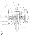
- is a view of the device of
Fig. 6 in the first position; - Fig. 8
- is a view of the device of
Fig. 6 in the second position; - Fig. 9
- is a perspective view of a device for clamping a weft thread according to a second embodiment;
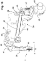
- Fig. 10
- is a second perspective view of the device for clamping a weft thread of
Fig. 9 . - Fig. 11
- is a top view of another device for clamping a weft thread according to the invention.
-
Fig. 1 and2 show a perspective view and a top view of adevice 1 for clamping a weft thread, arranged on a rapier weaving machine, also named gripper weaving machine. The rapier weaving machine is only partly shown. The rapier weaving machine comprises presentingdevices 2 for weft thread and agripper 3. In the depicted embodiment, also athread guiding element 4 and acutting device 5 for weft thread are provided. In the depicted embodiment, thecutting device 5 is attached to the frame of thedevice 1 for clampingweft thread 6 and forms an assembly with thedevice 1 for clampingweft thread 6. -
Weft threads 6 are schematically shown inFig. 2 . According to the insertion direction N, aweft thread 6 runs from the presentingdevice 2, via thegripper 3, thethread guiding element 4, thedevice 1 for clamping aweft thread 6, and thecutting device 5 to thecloth edge 8 and thewoven cloth 9 with thecloth line 7. Thecloth 9 can in this case support on a cloth support not shown. As indicated inFig. 2 thecloth edge 8 is a side edge of thecloth 9 that extends in warp direction, while thecloth line 7 is the beat-up edge of thecloth 9 that extends in weft direction. - The
thread guiding element 4 is preferably fixedly arranged on the weaving machine. Thethread guiding element 4 comprises aguide plate 11 arranged near thegripper 3, which guideplate 11 is directed in the insertion direction N. Further aguide plate 12 is provided between thegripper 3 and the presentingdevice 2 which is directed in the insertion direction N in order to support aweft thread 6 to be inserted close to the presentingdevice 2 at thegripper 3. - The
device 1 for clamping a weft thread is described in more detail with reference toFigures 3 to 8 , showing thedevice 1 for clamping a weft thread and parts of thedevice 1 for clamping a weft thread in detail. - The
device 1 comprises acentral clamping element 10 shown in more detail inFig. 4 , a firstouter clamping element 15, and a second outer clampingelement 16, as shown inFig. 5 . As best seen inFig. 6 , thecentral clamping element 10 is movable supported, this means is forced in two opposite clamping directions to an intermediate position P shown in amongst othersFig. 6 . Thecentral clamping element 10 is sandwiched between the firstouter clamping element 15 and the second outer clampingelement 16 and makes contact with the firstouter clamping element 15 and the second outer clampingelement 16 when positioned in the intermediate position P. In other words, both thefirst clamp 20 formed by thecentral clamping element 10 and the firstouter clamping element 15 and thesecond clamp 21 formed by thecentral clamping element 10 and the second outer clampingelement 16 are closed in the intermediate position P in order to clamp a weft thread, each. In the depicted embodiment, twoforce elements outer clamping element 15 towards thecentral clamping element 10, and the second outer clampingelement 16 towards thecentral clamping element 10, respectively. - The
device 1 further comprises adrive device 22 adapted for displacing, this means moving thecentral clamping element 10 out of the intermediate position P as shown inFig. 6 in two clamping directions K and L, this means in a clamping direction K to at least one first position and in a clamping direction L to at least one second position, for example in one clamping direction K downwards and in the other clamping direction L upwards in the orientation of thedevice 1 as shown in thefigures 6 to 8 , wherein as shown inFig. 7 , in the first position thecentral clamping element 10 is at a distance from the firstouter clamping element 15, for example in case of an openedfirst clamp 20, and as shown inFig. 8 , in the second position thecentral clamping element 10 is at a distance from the second outer clampingelement 16, for example in case of an openedsecond clamp 21. - As may be seen best in
Fig. 4 , thedrive device 22 is a pneumaticdouble acting cylinder 30 comprising apiston 23, whichpiston 23 is directly coupled to thecentral clamping element 10 for a transmission of motion via thepiston rod 24 of thepiston 23. Thecentral clamping element 10, thepiston rod 24 and thepiston 23 are mechanically coupled or manufactured as an assembly, so that thecentral clamping element 10 is moved directly by thepiston 23. Thepiston 23 is herein balanced by twosprings chamber piston 23 in a central position as long as no compressed air is fed. In consequence, without a pressure supply, thecentral clamping element 10 is held in the intermediate position. In other embodiments, the intermediate position is obtained by feeding compressed air to bothchambers central clamping element 10 is forced in a direction, while supplying compressed air to bothchambers - The
outer clamping elements force elements first clamp 20 and thesecond clamp 21 initially remain closed upon displacement of thecentral clamping element 10. Thedevice 1 further comprises anabutment element 17 arranged between the firstouter clamping element 15 and the second outer clampingelement 16 in the movement path of theouter clamping elements central clamping element 10 is larger than a height H2 of theabutment element 17, as may be seen inFigures 5 and6 . The difference in height between H1 and H2 defines the play over which theclamping elements abutment element 17 and without theclamps central clamping element 10 is arranged in the intermediate position as shown, theabutment element 17 does not make contact with any of theouter clamping elements abutment element 17 is fork shaped, wherein the two tips of the fork shaped element surround thecentral clamping element 10 without limiting a movement of thecentral clamping element 10 in the two clamping directions K and L. The two tips of theabutment element 17 may limit the movement of the clampingelements clamping elements - According to an embodiment not shown two abutment elements are provided, for example each of which formed by a fork shaped element. These two abutment elements are arranged at a distance from one another and can each co-operate with an associated
outer clamping element piece clamping element 17. - When moving the
central clamping element 10 downwards in clamping direction K, theforce element 18 loads the firstouter clamping element 15 in order to follow the movement of thecentral clamping element 10 until the firstouter clamping element 15 abuts against theabutment element 17 so that thefirst clamp 20 opens, while thesecond clamp 21 remains closed. When moving thecentral clamping element 10 upwards in clamping direction L, theforce element 19 loads the second outer clampingelement 16 in order to follow the movement of thecentral clamping element 10 until the second outer clampingelement 16 abuts against theabutment element 17 so that thesecond clamp 21 opens, while thefirst clamp 20 remains closed. In an embodiment, theabutment element 17 and thecentral clamping element 10 are aligned in an intermediate position, wherein through a slit 65 apositioning screw 29 is provided for aligning theabutment element 17 in relation to thecentral clamping element 10 in the intermediate position. As may be seen inFig. 4 analien screw 60 is arranged rotatable in thehousing 22. By screwing thealien screw 60 more or less into thehousing 22, the intermediate position of thepiston 23 can be set relatively accurately and also the force applied by thesprings piston 23 can be set. - As mentioned above, the
drive device 22 is a pneumatic actingdouble cylinder 30 comprising apiston 23, arranged between twochambers spring chamber chambers respective ducts valves - By supplying compressed air via the
duct 31 and thevalve 33 in thechamber 27 of thespring 13, thecentral clamping element 10 and the twoouter clamping elements outer clamping element 15 abuts against theabutment element 17 so that thefirst clamp 20 opens and thesecond clamp 21 remains closed. If compressed air is supplied via theduct 32 and thevalve 34 in thechamber 28 of thespring 14, thecentral clamping element 10 and the twoouter clamping elements element 16 abuts against theabutment element 17 so that thesecond clamp 21 opens and thefirst clamp 20 remains closed. If no compressed air is fed, then thesprings central clamping element 10 in its intermediate position. The strength of thesprings force elements - In an alternative embodiment, the
force elements springs springs force elements - In the embodiment shown, the
outer clamping elements shafts shafts piston rod 24, so that the guidingshafts piston rod 24 and thepiston rod 24 is displaceable inside the tubular shaped guidingshafts shafts outer clamping elements shafts piston rod 24. In the embodiment shown, the length of the tubular shaped guidingshafts outer clamping elements additional abutments abutment 51 forms part of aring element 66 and limits the movement of thefirst clamping element 15 in the second position, while theabutment 52 forms part of aring element 67 and limits the movement of thesecond clamping element 16 in the first position. When the firstouter clamping element 15 via the guidingshaft 25 abuts against theabutment 51, the firstouter clamping element 15 is almost not able to vibrate, since the firstouter clamping element 15 is held between theabutment 51 and thecentral clamping element 10, and a weft thread is with certainty clamped further by theclamp 20. When the second outer clampingelement 16 via the guidingshaft 26 abuts against theabutment 52, the second outer clampingelement 16 is almost not able to vibrate, since the second outer clampingelement 16 is held between theabutment 52 and thecentral clamping element 10, and a weft thread is with certainty clamped further by theclamp 21. At the tubular shaped guidingshafts outer clamping elements opening piston rod 24 is movable. - In an embodiment shown, the
central clamping element 10 is provided with adistal end 53 shaped as a wedge shaped tip. Thedistal end 54 of the firstouter clamping element 15 and thedistal end 55 of the second outer clampingelement 16 are each bent away from thecentral clamping element 10, more particularly bent in such a way that the distal ends 54, 55 each form anintake funnel distal end 53 of thecentral clamping element 10. The distal ends 53 and 54 form a receivingsection 58 for the one weft thread, while the distal ends 53 and 55 form a receivingsection 59 for the other weft thread. - As best seen in
Fig. 3 , thedevice 1 is arranged in amodule 35 and can be positioned with respect to the weaving machine using twopositioning elements device 1. Themodule 35, for example, comprises also thethread guiding element 4 that is arranged in insertion direction N upstream of thecentral clamping element 10 of thedevice 1. Themodule 35, for example, also comprises thecutting device 5 that is arranged in insertion direction N downstream of thecentral clamping element 10 of thedevice 1. According to a variant not shown, all aforementioned elements may be arranged separately at a settable distance from each other. -
Fig. 9 and10 show an alternative embodiment, wherein thedevice 1 is provided with amodule 35, whichmodule 35 is arranged to be movable towards and away from thegripper 3 according to arrow P in a plane parallel or approximately parallel to thecloth edge 8 of thewoven cloth 9. Thedevice 1 is similar to the device ofFigures 1 to 8 and the same or similar elements will be denoted by the same reference numerals. In the depicted embodiment, anarm 38 is provided that can be moved to and fro by adrive mechanism 39, such as a cam drive mechanism, arranged on aframe 40. Thedevice 1 is attached to thearm 38. - The
arm 38 is arranged on arotatable shaft 41, whichshaft 41 is driven via arod 42, acoupling rod 43 and alever 44 by thecams 48. The position of thecoupling rod 43 on thelever 44 may be adjusted by using abolt 45 arranged in aslot 46 provided on thelever 44 in order to set the moving course of thedevice 1. Aspring 47 forces thelever 44 into contact with thecams 48. In preferred embodiments, thedrive axis 49 for thecams 48 is synchronised with the movement of the weaving machine, for example via a mechanical coupling or via a drive by an own controllable drive motor, in order to avoid that thedevice 1 according to the invention may come into contact with areed 50 or with asley 63 on which a reed can be fixed, shown inFig. 2 . In an alternative embodiment, instead of a drive system with cams, a pneumatic system and/or an electromagnetic system can be provided for moving thedevice 1 towards and away from thegripper 3. In an embodiment, thevalves ducts frame 40. By moving thearm 38 in the rotation direction R, thedevice 1 according to the invention may be positioned towards or away from thegripper 3. Herein thedevice 1 can be arranged close to thegripper 3 during the taking up of a weft thread by thegripper 3 and during the taking up of a weft thread by thedevice 1 be arranged away from thegripper 3 and almost be arranged in the elongation of thecloth line 7. - According to the embodiment of
Fig. 11 at thethread guiding element 4, for example at the guidingplate 11 at the side of thethread guiding element 4 faced away from thecloth edge 8, asuction nozzle 64 may be arranged for catching and holding weft threads that are released unwanted from thedevice 1 for clamping a weft thread. This allows to still catch and keep such weft threads in thesuction nozzle 64, so that these weft threads still can be taken up and inserted by thegripper 3 during a next insertion and subsequently be clamped again in thedevice 1 for clamping weft thread according to the invention. - During the insertion of a weft thread, the
device 1 is brought in such a position that the inserted weft thread can be taken up in an openedclamp clamp device 1 is arranged so that during the taking up the weft thread extends almost perpendicular to the direction of the taking up of the weft thread in theclamp cutting device 5 between thedevice 1 and thecloth 9. During a subsequent insertion a weft thread presented by the presentingdevice 2 is taken up by thegripper 3 and inserted in the shed, wherein this weft thread is pulled out of thedevice 1 by thegripper 3 while the associatedclamp device 1. Preferably, the associatedclamp - The
device 1 for clamping a weft thread is adapted to co-operate with two weft threads. However, in embodiments not shown several such devices for clamping a weft thread are provided. The devices for clamping a weft thread are preferably each arranged on a movable frame, which thus allows to weave with more than two weft threads and more than two presenting devices for weft thread. In an embodiment, two devices according to the invention are used which are arranged mirror symmetrical to each other. At thecloth edge 8 thecloth 9 can be bound by so-called leno-threads which are arranged approximately parallel to and next to the warp threads. - The device and the method for clamping a weft thread according to the invention are not limited to the embodiments shown and described by way of example, but can also comprise variants and combinations of these embodiments that fall under the claims.
Claims (15)
- Device for clamping a weft thread (6) in a weaving machine, the device (1) comprises a central clamping element (10), a first outer clamping element (15) and a second outer clamping element (16), wherein the central clamping element (10) is forced in two opposite clamping directions (K, L) to an intermediate position (P), wherein the central clamping element (10) is sandwiched between the first outer clamping element (15) and the second outer clamping element (16) when the central clamping element (10) is positioned in the intermediate position (P), wherein both the first outer clamping element (15) and the second outer clamping element (16) abut against the central clamping element (10) in the intermediate position, the device (1) further comprises a drive device (22) adapted for displacing the central clamping element (10) out of the intermediate position (P) in two clamping directions (K, L), a first clamping direction (K) to at least a first position and a second clamping direction (L) to at least a second position, wherein in the first position the central clamping element (10) is at a distance from the first outer clamping element (15) and in the second position the central clamping element (10) is at a distance from the second outer clamping element (16),
characterized in that the drive device (22) comprises- a pneumatic cylinder (30) comprising at least a piston (23), wherein the piston (23) and/or a piston rod (24) of the piston (23) is formed integrally with or is mechanically coupled to the central clamping element (10) for a transmission of motion in the clamping directions (K, L) and- at least one abutment element (17) arranged between the first outer clamping element (15) and the second outer clamping element (16) for limiting a movement of the first outer clamping element (15) and the second outer clamping element (16) towards each other, wherein a height (H1) of the central clamping element (10) is larger than the total height (H2) of the at least one abutment element (17). - The device according to claim 1, characterized in that the pneumatic cylinder (30) is a double acting pneumatic cylinder, which is displaceable to the intermediate position, the first position and the second position.
- The device according to claim 1 or 2, characterized in that the pneumatic cylinder (30) comprises at least a spring (13, 14), preferably two springs, loading the piston (23).
- The device according to any one of claims 1 to 3, characterized in that the device (1) further comprises a first force element (18) forcing the first outer clamping element (15) towards the central clamping element (10) and a second force element (19) forcing the second outer clamping element (16) towards the central clamping element (10), wherein the at least one abutment element (17) limits a displacement of the first and the second outer clamping element (15, 16) caused by the displacement of the central clamping element (10) and a force applied by the first or the second force element (18, 19) on the first and the second outer clamping element (15, 16), respectively.
- The device according to any one of claims 1 to 4, characterized in that the first outer clamping element (15) and/or the second outer clamping element (16) are formed as a plate, which plate being fixed to a guiding shaft (25, 26).
- The device according to any one of claims 1 to 5, characterized in that the outer clamping elements (15, 16) comprise a guiding shaft (25, 26) that is guided coaxially with respect to a piston rod (24) of the piston (23).
- The device according to any one of claims 1 to 6, characterized in that the central clamping element (10) comprises a distal end (53), wherein the distal end (53) facing a weft thread (6) to be clamped forms an intake funnel (56, 57) with the distal end (54) of the first outer clamping element (15) and/or with the distal end (55) of the second outer clamping element (16).
- The device according to any one of claims 1 to 7, characterized in that the device (1) comprises an abutment (51) which limits the movement of the first outer clamping element (15) in the second position and comprises an abutment (52) which limits the movement of the second outer clamping element (16) in the first position.
- The device according to any one of claims 1 to 8, characterized in that the device (1) is arranged in a module (35).
- The device according to claim 9, characterized in that the module (35) further comprises at least a thread guiding element (4) arranged upstream of the central clamping element (10) in insertion direction (N).
- The device according to claim 9 or 10, characterized in that the module (35) comprises at least a cutting device (5) arranged downstream of the central clamping element (10) in insertion direction (N).
- The device according to any one of claims 9 to 11, characterized in that the module (35) is arranged to be movable towards and away from a gripper (3) in a plane approximately parallel or parallel to the cloth edge (8) of the cloth (9).
- Method for clamping a weft thread (6) in a weaving machine, wherein an inserted weft thread is introduced in a device (1) for clamping a weft thread (6) arranged next to a cloth edge (8) of the cloth (9), wherein the device (1) comprises a central clamping element (10), a first outer clamping element (15) and a second outer clamping element (16), wherein the central clamping element (10) is forced in two opposite clamping directions (K, L) to an intermediate position (P), wherein the central clamping element (10) is sandwiched between the first outer clamping element (15) and the second outer clamping element (16) when the central clamping element (10) is positioned in the intermediate position (P), wherein the central clamping element (10) is displaceable from an intermediate position (P) in two clamping directions (K, L), a first clamping direction (K) to at least a first position, wherein the central clamping element (10) is at a distance from the first outer clamping element (15), and a second clamping direction (L) to at least a second position, wherein the central clamping element (10) is at a distance from the second outer clamping element (16), characterized in that- -compressed air is supplied to a drive device (22) for displacing the central clamping element (10) in at least one of the intermediate position, the first position or the second position, and- a movement of the first outer clamping element (15) and the second outer clamping element (16) towards each other is limited by means of at least one abutment element (17) arranged between the first and the second outer clamping element (15, 16), wherein a height (H1) of the central clamping element (10) is larger than the total height (H2) of the at least one abutment element (17).
- Method according to claim 13, characterized in that the drive device (22) is a double acting cylinder (30) with a first chamber (27) and a second chamber (28), wherein the first chamber (27) is pressurized for moving the cylinder (30) in the first position and a second chamber (28) is pressurized for moving the cylinder (30) in the second position.
- Method according to claim 13 or 14, characterized in that the weft thread (6) is taken up by a gripper (3) and the weft thread (6) taken up by the gripper (3) is pulled out of the clamp (20, 21) while the clamp (20, 21) is still closed.
Applications Claiming Priority (2)
| Application Number | Priority Date | Filing Date | Title |
|---|---|---|---|
| BE2011/0444A BE1019807A3 (en) | 2011-07-12 | 2011-07-12 | DEVICE AND METHOD FOR CLOSING AN IMPOSITION WIRE |
| PCT/EP2012/062833 WO2013007551A2 (en) | 2011-07-12 | 2012-07-02 | Device and method for clamping a weft thread |
Publications (2)
| Publication Number | Publication Date |
|---|---|
| EP2732086A2 EP2732086A2 (en) | 2014-05-21 |
| EP2732086B1 true EP2732086B1 (en) | 2019-09-11 |
Family
ID=46456590
Family Applications (1)
| Application Number | Title | Priority Date | Filing Date |
|---|---|---|---|
| EP12731447.4A Active EP2732086B1 (en) | 2011-07-12 | 2012-07-02 | Device and method for clamping a weft thread |
Country Status (4)
| Country | Link |
|---|---|
| EP (1) | EP2732086B1 (en) |
| CN (1) | CN104302822B (en) |
| BE (1) | BE1019807A3 (en) |
| WO (1) | WO2013007551A2 (en) |
Families Citing this family (4)
| Publication number | Priority date | Publication date | Assignee | Title |
|---|---|---|---|---|
| BE1022146B1 (en) | 2014-06-13 | 2016-02-19 | Picanol | SELF-EDUCATION DEVICE FOR A WRAKING THREAD |
| DE102015217356B3 (en) * | 2015-09-10 | 2016-10-20 | Lindauer Dornier Gesellschaft Mit Beschränkter Haftung | Weaving machine with a device and method for holding, feeding and entering weft threads in a shed |
| BE1024401B1 (en) * | 2016-07-04 | 2018-02-13 | Picanol N.V. Naamloze Vennootschap | Device for clamping weft threads |
| CN114575020B (en) * | 2022-03-21 | 2023-05-23 | 武汉纺织大学 | Loom with automatic weft insertion device |
Family Cites Families (9)
| Publication number | Priority date | Publication date | Assignee | Title |
|---|---|---|---|---|
| CN1007742B (en) * | 1985-10-08 | 1990-04-25 | 普罗菲尔意大利有限公司 | Pneumatic auxiliary holder used in sewing machine |
| JP2762132B2 (en) * | 1989-10-04 | 1998-06-04 | 津田駒工業株式会社 | Weft insertion device for rapier looms |
| BE1006347A3 (en) | 1992-11-16 | 1994-07-26 | Picanol Nv | DEVICE FOR PRESENTING weft threads in weaving machines. |
| DE59306205D1 (en) | 1993-09-20 | 1997-05-22 | Rueti Ag Maschf | Arrangement for placing weft threads |
| DE10253341A1 (en) * | 2002-04-26 | 2003-11-13 | Volkmann Gmbh | Textile machine bobbin creel is raised or lowered by an articulated arm fixed to box-frame with four pivot point attachments and pneumatic cylinder |
| DE10255640B3 (en) * | 2002-11-28 | 2004-01-22 | Rexroth Mecman Gmbh | Pressure cylinder, in particular for a drafting system of a textile machine |
| BE1017684A3 (en) | 2007-07-12 | 2009-03-03 | Picanol Nv | METHOD FOR INSERTING AN END OF A WELDING THREAD INTO A SIDE OF A TISSUE AND A PNEUMATIC EDGE INSERT. |
| EP2034061B1 (en) * | 2007-09-10 | 2010-09-01 | ITEMA (Switzerland) Ltd. | Cutting device for a loom and method for operating the same |
| DE102008027131A1 (en) * | 2008-05-30 | 2009-12-03 | Picanol N.V. | Device for separating weft thread, has two blades, by which drives are moved relative to each other in allocation or for executing separation process, and drive is designed as pneumatic drive |
-
2011
- 2011-07-12 BE BE2011/0444A patent/BE1019807A3/en not_active IP Right Cessation
-
2012
- 2012-07-02 CN CN201280034291.5A patent/CN104302822B/en not_active Expired - Fee Related
- 2012-07-02 WO PCT/EP2012/062833 patent/WO2013007551A2/en not_active Ceased
- 2012-07-02 EP EP12731447.4A patent/EP2732086B1/en active Active
Non-Patent Citations (1)
| Title |
|---|
| None * |
Also Published As
| Publication number | Publication date |
|---|---|
| WO2013007551A3 (en) | 2014-03-13 |
| WO2013007551A2 (en) | 2013-01-17 |
| BE1019807A3 (en) | 2012-12-04 |
| CN104302822B (en) | 2017-06-13 |
| EP2732086A2 (en) | 2014-05-21 |
| CN104302822A (en) | 2015-01-21 |
Similar Documents
| Publication | Publication Date | Title |
|---|---|---|
| EP2176455B1 (en) | Method for tucking an end of a weft thread into a selvedge of a fabric, and pneumatic tuck-in device | |
| WO2013007551A2 (en) | Device and method for clamping a weft thread | |
| KR20120107085A (en) | Material feeding device having gripping member linkage and method of operation thereof | |
| US10472745B2 (en) | Weaving machine with an apparatus as well as method for holding, feeding and inserting weft threads in a loom shed | |
| CZ283258B6 (en) | Weft inserting brake of weaving loom | |
| KR20100097012A (en) | Thread cutting device of sewing machine | |
| JP2009068157A (en) | Cutting device for loom and operation method thereof | |
| JP7017991B2 (en) | Weft operation device without pseudo selvage in gripper loom | |
| JP2000154444A (en) | Controllable weft yarn cramping/presenting device of loom | |
| EP2734663B1 (en) | Single-gripper weaving loom | |
| US8875747B2 (en) | Gripper head for the insertion of weft threads on a gripper weaving machine | |
| CN109415849B (en) | Device for clamping weft threads | |
| CN101454491A (en) | Method and apparatus for forming a selvedge on a gripper weaving machine | |
| EP2440696B1 (en) | Gripper unit, control system for a gripper unit and weaving machine | |
| CN107580638B (en) | Gripper opener for looms | |
| EP3014004B1 (en) | Method and device for inserting two weft threads at the same time | |
| EP1266986B1 (en) | Weft yarn clamp for clamping and releasing weft yarns of a weaving machine | |
| EP3155155B1 (en) | Selvedge forming device for a weft thread | |
| CN103003479A (en) | Gripper and weft thread insertion device for a rapier weaving machine | |
| HK1178578B (en) | Gripper and weft-thread insertion device for a gripper weaving machine | |
| HK1116226A (en) | Accelerating device for a loom |
Legal Events
| Date | Code | Title | Description |
|---|---|---|---|
| PUAI | Public reference made under article 153(3) epc to a published international application that has entered the european phase |
Free format text: ORIGINAL CODE: 0009012 |
|
| 17P | Request for examination filed |
Effective date: 20131111 |
|
| AK | Designated contracting states |
Kind code of ref document: A2 Designated state(s): AL AT BE BG CH CY CZ DE DK EE ES FI FR GB GR HR HU IE IS IT LI LT LU LV MC MK MT NL NO PL PT RO RS SE SI SK SM TR |
|
| DAX | Request for extension of the european patent (deleted) | ||
| STAA | Information on the status of an ep patent application or granted ep patent |
Free format text: STATUS: EXAMINATION IS IN PROGRESS |
|
| 17Q | First examination report despatched |
Effective date: 20180613 |
|
| GRAP | Despatch of communication of intention to grant a patent |
Free format text: ORIGINAL CODE: EPIDOSNIGR1 |
|
| STAA | Information on the status of an ep patent application or granted ep patent |
Free format text: STATUS: GRANT OF PATENT IS INTENDED |
|
| INTG | Intention to grant announced |
Effective date: 20190320 |
|
| GRAS | Grant fee paid |
Free format text: ORIGINAL CODE: EPIDOSNIGR3 |
|
| GRAJ | Information related to disapproval of communication of intention to grant by the applicant or resumption of examination proceedings by the epo deleted |
Free format text: ORIGINAL CODE: EPIDOSDIGR1 |
|
| GRAL | Information related to payment of fee for publishing/printing deleted |
Free format text: ORIGINAL CODE: EPIDOSDIGR3 |
|
| STAA | Information on the status of an ep patent application or granted ep patent |
Free format text: STATUS: EXAMINATION IS IN PROGRESS |
|
| GRAR | Information related to intention to grant a patent recorded |
Free format text: ORIGINAL CODE: EPIDOSNIGR71 |
|
| STAA | Information on the status of an ep patent application or granted ep patent |
Free format text: STATUS: GRANT OF PATENT IS INTENDED |
|
| GRAA | (expected) grant |
Free format text: ORIGINAL CODE: 0009210 |
|
| STAA | Information on the status of an ep patent application or granted ep patent |
Free format text: STATUS: THE PATENT HAS BEEN GRANTED |
|
| INTC | Intention to grant announced (deleted) | ||
| AK | Designated contracting states |
Kind code of ref document: B1 Designated state(s): AL AT BE BG CH CY CZ DE DK EE ES FI FR GB GR HR HU IE IS IT LI LT LU LV MC MK MT NL NO PL PT RO RS SE SI SK SM TR |
|
| INTG | Intention to grant announced |
Effective date: 20190802 |
|
| REG | Reference to a national code |
Ref country code: GB Ref legal event code: FG4D |
|
| REG | Reference to a national code |
Ref country code: CH Ref legal event code: EP |
|
| REG | Reference to a national code |
Ref country code: AT Ref legal event code: REF Ref document number: 1178571 Country of ref document: AT Kind code of ref document: T Effective date: 20190915 |
|
| REG | Reference to a national code |
Ref country code: DE Ref legal event code: R096 Ref document number: 602012063866 Country of ref document: DE Ref country code: IE Ref legal event code: FG4D |
|
| REG | Reference to a national code |
Ref country code: NL Ref legal event code: MP Effective date: 20190911 |
|
| REG | Reference to a national code |
Ref country code: LT Ref legal event code: MG4D |
|
| PG25 | Lapsed in a contracting state [announced via postgrant information from national office to epo] |
Ref country code: LT Free format text: LAPSE BECAUSE OF FAILURE TO SUBMIT A TRANSLATION OF THE DESCRIPTION OR TO PAY THE FEE WITHIN THE PRESCRIBED TIME-LIMIT Effective date: 20190911 Ref country code: HR Free format text: LAPSE BECAUSE OF FAILURE TO SUBMIT A TRANSLATION OF THE DESCRIPTION OR TO PAY THE FEE WITHIN THE PRESCRIBED TIME-LIMIT Effective date: 20190911 Ref country code: FI Free format text: LAPSE BECAUSE OF FAILURE TO SUBMIT A TRANSLATION OF THE DESCRIPTION OR TO PAY THE FEE WITHIN THE PRESCRIBED TIME-LIMIT Effective date: 20190911 Ref country code: SE Free format text: LAPSE BECAUSE OF FAILURE TO SUBMIT A TRANSLATION OF THE DESCRIPTION OR TO PAY THE FEE WITHIN THE PRESCRIBED TIME-LIMIT Effective date: 20190911 Ref country code: NO Free format text: LAPSE BECAUSE OF FAILURE TO SUBMIT A TRANSLATION OF THE DESCRIPTION OR TO PAY THE FEE WITHIN THE PRESCRIBED TIME-LIMIT Effective date: 20191211 Ref country code: BG Free format text: LAPSE BECAUSE OF FAILURE TO SUBMIT A TRANSLATION OF THE DESCRIPTION OR TO PAY THE FEE WITHIN THE PRESCRIBED TIME-LIMIT Effective date: 20191211 |
|
| PG25 | Lapsed in a contracting state [announced via postgrant information from national office to epo] |
Ref country code: LV Free format text: LAPSE BECAUSE OF FAILURE TO SUBMIT A TRANSLATION OF THE DESCRIPTION OR TO PAY THE FEE WITHIN THE PRESCRIBED TIME-LIMIT Effective date: 20190911 Ref country code: ES Free format text: LAPSE BECAUSE OF FAILURE TO SUBMIT A TRANSLATION OF THE DESCRIPTION OR TO PAY THE FEE WITHIN THE PRESCRIBED TIME-LIMIT Effective date: 20190911 Ref country code: AL Free format text: LAPSE BECAUSE OF FAILURE TO SUBMIT A TRANSLATION OF THE DESCRIPTION OR TO PAY THE FEE WITHIN THE PRESCRIBED TIME-LIMIT Effective date: 20190911 Ref country code: RS Free format text: LAPSE BECAUSE OF FAILURE TO SUBMIT A TRANSLATION OF THE DESCRIPTION OR TO PAY THE FEE WITHIN THE PRESCRIBED TIME-LIMIT Effective date: 20190911 Ref country code: GR Free format text: LAPSE BECAUSE OF FAILURE TO SUBMIT A TRANSLATION OF THE DESCRIPTION OR TO PAY THE FEE WITHIN THE PRESCRIBED TIME-LIMIT Effective date: 20191212 |
|
| REG | Reference to a national code |
Ref country code: AT Ref legal event code: MK05 Ref document number: 1178571 Country of ref document: AT Kind code of ref document: T Effective date: 20190911 |
|
| PG25 | Lapsed in a contracting state [announced via postgrant information from national office to epo] |
Ref country code: AT Free format text: LAPSE BECAUSE OF FAILURE TO SUBMIT A TRANSLATION OF THE DESCRIPTION OR TO PAY THE FEE WITHIN THE PRESCRIBED TIME-LIMIT Effective date: 20190911 Ref country code: PL Free format text: LAPSE BECAUSE OF FAILURE TO SUBMIT A TRANSLATION OF THE DESCRIPTION OR TO PAY THE FEE WITHIN THE PRESCRIBED TIME-LIMIT Effective date: 20190911 Ref country code: EE Free format text: LAPSE BECAUSE OF FAILURE TO SUBMIT A TRANSLATION OF THE DESCRIPTION OR TO PAY THE FEE WITHIN THE PRESCRIBED TIME-LIMIT Effective date: 20190911 Ref country code: PT Free format text: LAPSE BECAUSE OF FAILURE TO SUBMIT A TRANSLATION OF THE DESCRIPTION OR TO PAY THE FEE WITHIN THE PRESCRIBED TIME-LIMIT Effective date: 20200113 Ref country code: NL Free format text: LAPSE BECAUSE OF FAILURE TO SUBMIT A TRANSLATION OF THE DESCRIPTION OR TO PAY THE FEE WITHIN THE PRESCRIBED TIME-LIMIT Effective date: 20190911 Ref country code: RO Free format text: LAPSE BECAUSE OF FAILURE TO SUBMIT A TRANSLATION OF THE DESCRIPTION OR TO PAY THE FEE WITHIN THE PRESCRIBED TIME-LIMIT Effective date: 20190911 |
|
| PG25 | Lapsed in a contracting state [announced via postgrant information from national office to epo] |
Ref country code: SM Free format text: LAPSE BECAUSE OF FAILURE TO SUBMIT A TRANSLATION OF THE DESCRIPTION OR TO PAY THE FEE WITHIN THE PRESCRIBED TIME-LIMIT Effective date: 20190911 Ref country code: SK Free format text: LAPSE BECAUSE OF FAILURE TO SUBMIT A TRANSLATION OF THE DESCRIPTION OR TO PAY THE FEE WITHIN THE PRESCRIBED TIME-LIMIT Effective date: 20190911 Ref country code: CZ Free format text: LAPSE BECAUSE OF FAILURE TO SUBMIT A TRANSLATION OF THE DESCRIPTION OR TO PAY THE FEE WITHIN THE PRESCRIBED TIME-LIMIT Effective date: 20190911 Ref country code: IS Free format text: LAPSE BECAUSE OF FAILURE TO SUBMIT A TRANSLATION OF THE DESCRIPTION OR TO PAY THE FEE WITHIN THE PRESCRIBED TIME-LIMIT Effective date: 20200224 |
|
| REG | Reference to a national code |
Ref country code: DE Ref legal event code: R097 Ref document number: 602012063866 Country of ref document: DE |
|
| PLBE | No opposition filed within time limit |
Free format text: ORIGINAL CODE: 0009261 |
|
| STAA | Information on the status of an ep patent application or granted ep patent |
Free format text: STATUS: NO OPPOSITION FILED WITHIN TIME LIMIT |
|
| PG2D | Information on lapse in contracting state deleted |
Ref country code: IS |
|
| PG25 | Lapsed in a contracting state [announced via postgrant information from national office to epo] |
Ref country code: DK Free format text: LAPSE BECAUSE OF FAILURE TO SUBMIT A TRANSLATION OF THE DESCRIPTION OR TO PAY THE FEE WITHIN THE PRESCRIBED TIME-LIMIT Effective date: 20190911 Ref country code: IS Free format text: LAPSE BECAUSE OF FAILURE TO SUBMIT A TRANSLATION OF THE DESCRIPTION OR TO PAY THE FEE WITHIN THE PRESCRIBED TIME-LIMIT Effective date: 20200112 |
|
| 26N | No opposition filed |
Effective date: 20200615 |
|
| PG25 | Lapsed in a contracting state [announced via postgrant information from national office to epo] |
Ref country code: SI Free format text: LAPSE BECAUSE OF FAILURE TO SUBMIT A TRANSLATION OF THE DESCRIPTION OR TO PAY THE FEE WITHIN THE PRESCRIBED TIME-LIMIT Effective date: 20190911 |
|
| PG25 | Lapsed in a contracting state [announced via postgrant information from national office to epo] |
Ref country code: MC Free format text: LAPSE BECAUSE OF FAILURE TO SUBMIT A TRANSLATION OF THE DESCRIPTION OR TO PAY THE FEE WITHIN THE PRESCRIBED TIME-LIMIT Effective date: 20190911 |
|
| REG | Reference to a national code |
Ref country code: CH Ref legal event code: PL |
|
| GBPC | Gb: european patent ceased through non-payment of renewal fee |
Effective date: 20200702 |
|
| PG25 | Lapsed in a contracting state [announced via postgrant information from national office to epo] |
Ref country code: CH Free format text: LAPSE BECAUSE OF NON-PAYMENT OF DUE FEES Effective date: 20200731 Ref country code: IE Free format text: LAPSE BECAUSE OF NON-PAYMENT OF DUE FEES Effective date: 20200702 Ref country code: LI Free format text: LAPSE BECAUSE OF NON-PAYMENT OF DUE FEES Effective date: 20200731 Ref country code: FR Free format text: LAPSE BECAUSE OF NON-PAYMENT OF DUE FEES Effective date: 20200731 Ref country code: GB Free format text: LAPSE BECAUSE OF NON-PAYMENT OF DUE FEES Effective date: 20200702 Ref country code: LU Free format text: LAPSE BECAUSE OF NON-PAYMENT OF DUE FEES Effective date: 20200702 |
|
| PG25 | Lapsed in a contracting state [announced via postgrant information from national office to epo] |
Ref country code: MT Free format text: LAPSE BECAUSE OF FAILURE TO SUBMIT A TRANSLATION OF THE DESCRIPTION OR TO PAY THE FEE WITHIN THE PRESCRIBED TIME-LIMIT Effective date: 20190911 Ref country code: CY Free format text: LAPSE BECAUSE OF FAILURE TO SUBMIT A TRANSLATION OF THE DESCRIPTION OR TO PAY THE FEE WITHIN THE PRESCRIBED TIME-LIMIT Effective date: 20190911 |
|
| PG25 | Lapsed in a contracting state [announced via postgrant information from national office to epo] |
Ref country code: MK Free format text: LAPSE BECAUSE OF FAILURE TO SUBMIT A TRANSLATION OF THE DESCRIPTION OR TO PAY THE FEE WITHIN THE PRESCRIBED TIME-LIMIT Effective date: 20190911 |
|
| P01 | Opt-out of the competence of the unified patent court (upc) registered |
Effective date: 20230519 |
|
| PGFP | Annual fee paid to national office [announced via postgrant information from national office to epo] |
Ref country code: TR Payment date: 20230621 Year of fee payment: 12 |
|
| PGFP | Annual fee paid to national office [announced via postgrant information from national office to epo] |
Ref country code: BE Payment date: 20250613 Year of fee payment: 14 |
|
| PGFP | Annual fee paid to national office [announced via postgrant information from national office to epo] |
Ref country code: DE Payment date: 20250723 Year of fee payment: 14 |
|
| PGFP | Annual fee paid to national office [announced via postgrant information from national office to epo] |
Ref country code: IT Payment date: 20250731 Year of fee payment: 14 |