EP2731168B1 - Einrichtung zum elektrischen Zusammenschalten von Zellen eines Batteriepacks mittels Zellverbindern und Batteriepack mit solchen Zellverbindern - Google Patents
Einrichtung zum elektrischen Zusammenschalten von Zellen eines Batteriepacks mittels Zellverbindern und Batteriepack mit solchen Zellverbindern Download PDFInfo
- Publication number
- EP2731168B1 EP2731168B1 EP14000459.9A EP14000459A EP2731168B1 EP 2731168 B1 EP2731168 B1 EP 2731168B1 EP 14000459 A EP14000459 A EP 14000459A EP 2731168 B1 EP2731168 B1 EP 2731168B1
- Authority
- EP
- European Patent Office
- Prior art keywords
- cell
- mounting plate
- battery pack
- cell connectors
- bracket
- Prior art date
- Legal status (The legal status is an assumption and is not a legal conclusion. Google has not performed a legal analysis and makes no representation as to the accuracy of the status listed.)
- Not-in-force
Links
- 239000004020 conductor Substances 0.000 claims description 18
- 239000000463 material Substances 0.000 claims description 8
- 229910052782 aluminium Inorganic materials 0.000 claims description 6
- XAGFODPZIPBFFR-UHFFFAOYSA-N aluminium Chemical compound [Al] XAGFODPZIPBFFR-UHFFFAOYSA-N 0.000 claims description 6
- RYGMFSIKBFXOCR-UHFFFAOYSA-N Copper Chemical compound [Cu] RYGMFSIKBFXOCR-UHFFFAOYSA-N 0.000 claims description 5
- 229910000881 Cu alloy Inorganic materials 0.000 claims description 5
- 229910052802 copper Inorganic materials 0.000 claims description 5
- 239000010949 copper Substances 0.000 claims description 5
- 238000000034 method Methods 0.000 claims description 5
- 229910000838 Al alloy Inorganic materials 0.000 claims description 4
- PXHVJJICTQNCMI-UHFFFAOYSA-N Nickel Chemical compound [Ni] PXHVJJICTQNCMI-UHFFFAOYSA-N 0.000 claims description 4
- 229910000831 Steel Inorganic materials 0.000 claims description 4
- 239000010959 steel Substances 0.000 claims description 4
- 238000003466 welding Methods 0.000 claims description 4
- 229910052759 nickel Inorganic materials 0.000 claims description 2
- 229910000990 Ni alloy Inorganic materials 0.000 claims 1
- 239000004411 aluminium Substances 0.000 claims 1
- 238000005476 soldering Methods 0.000 claims 1
- 210000004027 cell Anatomy 0.000 description 122
- 238000005452 bending Methods 0.000 description 3
- 238000001746 injection moulding Methods 0.000 description 3
- 230000001419 dependent effect Effects 0.000 description 2
- 230000001066 destructive effect Effects 0.000 description 2
- 238000005516 engineering process Methods 0.000 description 2
- 238000010409 ironing Methods 0.000 description 2
- 238000003825 pressing Methods 0.000 description 2
- 238000010792 warming Methods 0.000 description 2
- 230000004323 axial length Effects 0.000 description 1
- 230000003750 conditioning effect Effects 0.000 description 1
- 230000007423 decrease Effects 0.000 description 1
- 238000001514 detection method Methods 0.000 description 1
- 238000011161 development Methods 0.000 description 1
- 230000018109 developmental process Effects 0.000 description 1
- 238000006073 displacement reaction Methods 0.000 description 1
- 230000005489 elastic deformation Effects 0.000 description 1
- 238000010292 electrical insulation Methods 0.000 description 1
- 239000012777 electrically insulating material Substances 0.000 description 1
- 238000004146 energy storage Methods 0.000 description 1
- 238000003780 insertion Methods 0.000 description 1
- 230000037431 insertion Effects 0.000 description 1
- 238000004519 manufacturing process Methods 0.000 description 1
- 238000005259 measurement Methods 0.000 description 1
- 239000007769 metal material Substances 0.000 description 1
- 238000012544 monitoring process Methods 0.000 description 1
- 210000003339 pole cell Anatomy 0.000 description 1
- 229920000642 polymer Polymers 0.000 description 1
- 238000002360 preparation method Methods 0.000 description 1
- 230000000284 resting effect Effects 0.000 description 1
- 230000000717 retained effect Effects 0.000 description 1
- 230000035939 shock Effects 0.000 description 1
- 125000006850 spacer group Chemical group 0.000 description 1
- 238000003860 storage Methods 0.000 description 1
- 210000002105 tongue Anatomy 0.000 description 1
Images


Classifications
-
- H—ELECTRICITY
- H01—ELECTRIC ELEMENTS
- H01M—PROCESSES OR MEANS, e.g. BATTERIES, FOR THE DIRECT CONVERSION OF CHEMICAL ENERGY INTO ELECTRICAL ENERGY
- H01M10/00—Secondary cells; Manufacture thereof
- H01M10/42—Methods or arrangements for servicing or maintenance of secondary cells or secondary half-cells
- H01M10/425—Structural combination with electronic components, e.g. electronic circuits integrated to the outside of the casing
-
- H—ELECTRICITY
- H01—ELECTRIC ELEMENTS
- H01M—PROCESSES OR MEANS, e.g. BATTERIES, FOR THE DIRECT CONVERSION OF CHEMICAL ENERGY INTO ELECTRICAL ENERGY
- H01M50/00—Constructional details or processes of manufacture of the non-active parts of electrochemical cells other than fuel cells, e.g. hybrid cells
- H01M50/50—Current conducting connections for cells or batteries
- H01M50/502—Interconnectors for connecting terminals of adjacent batteries; Interconnectors for connecting cells outside a battery casing
- H01M50/521—Interconnectors for connecting terminals of adjacent batteries; Interconnectors for connecting cells outside a battery casing characterised by the material
- H01M50/522—Inorganic material
-
- H—ELECTRICITY
- H01—ELECTRIC ELEMENTS
- H01M—PROCESSES OR MEANS, e.g. BATTERIES, FOR THE DIRECT CONVERSION OF CHEMICAL ENERGY INTO ELECTRICAL ENERGY
- H01M50/00—Constructional details or processes of manufacture of the non-active parts of electrochemical cells other than fuel cells, e.g. hybrid cells
- H01M50/20—Mountings; Secondary casings or frames; Racks, modules or packs; Suspension devices; Shock absorbers; Transport or carrying devices; Holders
- H01M50/204—Racks, modules or packs for multiple batteries or multiple cells
- H01M50/207—Racks, modules or packs for multiple batteries or multiple cells characterised by their shape
- H01M50/213—Racks, modules or packs for multiple batteries or multiple cells characterised by their shape adapted for cells having curved cross-section, e.g. round or elliptic
-
- H—ELECTRICITY
- H01—ELECTRIC ELEMENTS
- H01M—PROCESSES OR MEANS, e.g. BATTERIES, FOR THE DIRECT CONVERSION OF CHEMICAL ENERGY INTO ELECTRICAL ENERGY
- H01M50/00—Constructional details or processes of manufacture of the non-active parts of electrochemical cells other than fuel cells, e.g. hybrid cells
- H01M50/50—Current conducting connections for cells or batteries
- H01M50/502—Interconnectors for connecting terminals of adjacent batteries; Interconnectors for connecting cells outside a battery casing
- H01M50/509—Interconnectors for connecting terminals of adjacent batteries; Interconnectors for connecting cells outside a battery casing characterised by the type of connection, e.g. mixed connections
- H01M50/51—Connection only in series
-
- H—ELECTRICITY
- H01—ELECTRIC ELEMENTS
- H01M—PROCESSES OR MEANS, e.g. BATTERIES, FOR THE DIRECT CONVERSION OF CHEMICAL ENERGY INTO ELECTRICAL ENERGY
- H01M50/00—Constructional details or processes of manufacture of the non-active parts of electrochemical cells other than fuel cells, e.g. hybrid cells
- H01M50/50—Current conducting connections for cells or batteries
- H01M50/502—Interconnectors for connecting terminals of adjacent batteries; Interconnectors for connecting cells outside a battery casing
- H01M50/514—Methods for interconnecting adjacent batteries or cells
- H01M50/516—Methods for interconnecting adjacent batteries or cells by welding, soldering or brazing
-
- Y—GENERAL TAGGING OF NEW TECHNOLOGICAL DEVELOPMENTS; GENERAL TAGGING OF CROSS-SECTIONAL TECHNOLOGIES SPANNING OVER SEVERAL SECTIONS OF THE IPC; TECHNICAL SUBJECTS COVERED BY FORMER USPC CROSS-REFERENCE ART COLLECTIONS [XRACs] AND DIGESTS
- Y02—TECHNOLOGIES OR APPLICATIONS FOR MITIGATION OR ADAPTATION AGAINST CLIMATE CHANGE
- Y02E—REDUCTION OF GREENHOUSE GAS [GHG] EMISSIONS, RELATED TO ENERGY GENERATION, TRANSMISSION OR DISTRIBUTION
- Y02E60/00—Enabling technologies; Technologies with a potential or indirect contribution to GHG emissions mitigation
- Y02E60/10—Energy storage using batteries
-
- Y—GENERAL TAGGING OF NEW TECHNOLOGICAL DEVELOPMENTS; GENERAL TAGGING OF CROSS-SECTIONAL TECHNOLOGIES SPANNING OVER SEVERAL SECTIONS OF THE IPC; TECHNICAL SUBJECTS COVERED BY FORMER USPC CROSS-REFERENCE ART COLLECTIONS [XRACs] AND DIGESTS
- Y02—TECHNOLOGIES OR APPLICATIONS FOR MITIGATION OR ADAPTATION AGAINST CLIMATE CHANGE
- Y02P—CLIMATE CHANGE MITIGATION TECHNOLOGIES IN THE PRODUCTION OR PROCESSING OF GOODS
- Y02P70/00—Climate change mitigation technologies in the production process for final industrial or consumer products
- Y02P70/50—Manufacturing or production processes characterised by the final manufactured product
Definitions
- the invention relates to a device for electrically interconnecting cells of a battery pack by means of cell connectors and a battery pack, in particular as energy storage for the electromotive traction and stationary applications, according to the respective preamble of the main claims.
- Cell connectors are out of the WO 2009/080148 A2 Known in the form of a perforated at both ends, massive high-current bridging bar between adjacent non-identical cell poles of the battery pack in series to be switched individual electrochemical cells.
- shims are used whose outer diameter is smaller and whose axial length is greater than the respective hole.
- the freely projecting poles of the cells attack.
- Each of the compensation sleeves moves within its hole in accordance with the production-related tolerances of the pole positions. Subsequently, the individually positioned compensation sleeves are welded on the one hand with their cell poles and on the other hand with the cell connector.
- the latter disadvantage is in the DE 1 98 10 746 B4 fixed by a circuit board.
- the conductor tracks formed therefrom lead from the cell poles located along the edge of the board to the central area of the board, which is equipped with a circuit for battery management, and to shunts for balancing the charging states of the individual cells with one another and to multiple plugs as data interfaces.
- the printed circuit boards are stuck in contact with PCB holes on the ending in a plane cell poles. Pierced latch-type cell connectors will be on each two cell poles plugged, and this two-layer arrangement of cell connectors and underlying circuit board is finally braced by screwing the cell poles against the front ends of the cells.
- circuit board is rigidly bolted in each case under much overdetermined storage between the massive cell connectors and the cell front ends, while operating shocks and temperature-dependent forces from the cells on the board on the cell connectors act, a flexible material is selected for the board. But this conjures up the risk of breaks in the tracks just in the immediate vicinity of the pole fittings, and thus the risk of failure of the entire battery pack of such a traction battery because then no longer functional battery management.
- the present invention is based on the technical problem of specifying a device of generic type which is reliable in operation with easy-to-use pole connection technology, which also opens up advantageous handling options for connecting battery management measures.
- the cell connectors can each be designed essentially as flexible stirrups made of electrically conductive material, which - depending on the mutual arrangement of two sixteenzuchafferder cells, for example, in their course aligned with each other - can be set in their connection area on a mounting plate made of electrically insulating material.
- Each bracket can be with its remote from the connection area, free end on the mounting plate, in particular slidably flexible, supported. All attached to a mounting plate according to the geometry of the Zellpolan angel cell connectors can be connected substantially simultaneously with cell poles by the mounting plate with its cell connectors applied to the cells, in particular pressed on, and optionally additionally locked or otherwise supported. Vibrational or operational temperature-related displacements or changes in position of the cell poles can be compensated.
- positional changes can be compensated or compensated by steepening or flattening of the flanks on both sides of the apex of the elastically yielding stirrups, shifting their free ends supported in the manner of bending springs against the mounting plate. It is also possible that position changes are compensated by resilient, in particular meandering structures between bracket and connection area. This can initiate destructive pressure or bending stresses be effectively prevented by the cell connectors via the cell poles into the cells.
- each bracket if present preferably in his lifted off from the mounting plate center or apex area, a hole whose surface is preferably smaller than the end face of the cell poles, so that when placed on the battery pack mounting plate of the hole edge on the end face of a Cell pole is pressed.
- the mounting plate in turn has coaxially to these holes through openings slightly larger diameter, through which the cell connector strap finally connected at their hole edges with the end faces of the cell poles materially connected, in particular laser welded or soldered.
- cell connectors are suitably made of a sheet material with sufficient spring and power line properties, such as sheet steel or preferably made of copper, a copper alloy, aluminum or an aluminum alloy.
- the cell connectors are punched out with insertion of the holes and, if desired, thereby arched up in the environment on both sides of a hole from its original plane to the temples.
- plug pins for example for battery management, can be designed to connect measurement and control circuits to the cell poles.
- a battery pack 11 has a number of e.g. cylindrical, axially parallel mounted cells 12, the cell poles 13 here at opposite ends 14 of the respective cell 12 emerge from this and lie with their end faces 26 substantially in each case in an upper or lower plane.
- the cells 12 arranged here in two rows are oriented in such a way that alternating polarities +/- are adjacent to one another at the cell poles 13.
- a flexible high-current cell connector 15 For the below considered electrical series or series connection of the cells 12 for obtaining their sum voltage as the output voltage of the battery pack 5 11 at its battery terminals 30 are always two mutually unequal + +/- these cell poles 13 by means of a flexible high-current cell connector 15 according to the invention connected together.
- These cell connectors 15 are, as in Fig.1 sketched in such a geometric sequence on two preferably made by plastic injection molding mounting plates 16 electrically isolated from each other (see also Fig.2 ) that they - with pressing the mounting plates 16 in the direction of the upper and lower ends 14 of the cells 12 - come against the end faces 26 of the cell poles 13 to the plant. With this simple handling of equipped with dual-wing cell connectors 15 mounting plate 16 all cell poles 13 of a cell front end 14 are electrically connected in series in one go.
- the cells 12 are positioned and retained on each of the two ends 14 in each case in a molded from electrically insulating plastic mounting frame 17 positive and non-positive to the battery pack 11 and supported.
- the mounting frame 17 is equipped with molded fastening means 18, approximately as outlined edge locking hooks, for the mounting of the mounting plate 16. This is thus merely, with resilient attachment of the cell connector 15 against the ZellpolStirn vom 26, to press between these fasteners 18 until it locks in the mounting frame 17 into it. This can also be done without problems by a relatively simple designed automatic assembly machine.
- each cell connector 15 for this series connection technique two here according to the adjacent arrangement of the unequal pole cell poles in their bow profile aligned, from the cell-facing surface plane of the created in the plastic injection molding mounting plate 16 elastically bulging bracket 19. These are fixed in their resting on the mounting plate 16 connecting or center portion 20 on the mounting plate 16, such as by rivet-like hot caulking by mounting holes 21 projecting pins that (not visible in the drawing) are formed on this connector-side surface of the mounting plate 16.
- mounting holes 21 projecting pins projecting pins that (not visible in the drawing) are formed on this connector-side surface of the mounting plate 16.
- free ends 22 of the respective cell connector 15 are the bracket 19 against the surface of the mounting plate 16, under leaf spring tension supporting, loose.
- the height of the vertex-curvature of the spring bracket 19 decreases elastically via the mounting plate 16 when on the apex portion 23 in the direction of the mounting plate 16 from the end face 26 of a cell pole 13 ago (in the cell connector assembly, or in Operation due to warming) increasingly pressure is exerted.
- the center distance corresponds approximately to the center distance of sixteenzusplenden by means of the cell connector 15 Zellpole 13.
- the hole geometry is smaller than the end face 26 of the cell pole 13 pressing against the hole 25 in the apex region 23.
- it is a round hole 25 whose diameter is smaller than the shortest diagonal above the pole face 26.
- the cell connectors 15 are preferably punched out as wide short strips of a copper alloy band, introducing the apex holes 25 and the mounting holes 21, here centrally between the two holes 25, and bulging of the respective apex portion 23 of the bracket 19 and folding the free bracket Ends 22.
- the cell poles 13 are not made of copper, but, in particular for lithium-polymer batteries for traction purposes, depending on the electrical polarity of aluminum or steel.
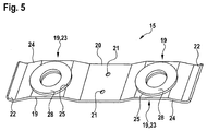
- unmixed welding of the cell poles 13 with the cell connectors 15 is therefore expediently per bracket 19 one, here approximately annular, fitting 28 made of aluminum or steel or nickel in the two bracket holes 25 frictionally fitted, see.
- Figure 5 in any case, from a material that corresponds by welding technology to that of the cell pole end face 26 that bears against it.
- the remaining in the connecting pieces 28 opening surfaces meet again the criterion that in each case their contour in each case in sections over the end face 26 of the adjacent cell pole 13 extends to be welded directly behind the access opening 27 so.
- the two not equipped with cell connectors cell poles 13 at the beginning and at the end of the outlined series circuit are, according to Figure 3 through plate recesses 29 therethrough Fig.1 as a positive or negative battery connection 30 accessible.
- a device for electrical interconnection of cells 12 of a battery pack 11 by means of cell connectors 15 and a battery pack 11 with such cell connectors 15 characterized by being particularly easy to install and reliable, that according to the invention at least one on the battery pack 11 in a mounting frame 17 to be latched mounting plate 16, in accordance with the geometric specification of interconnected cell poles 13, with electrically mutually insulated cell connectors 15 is fitted, the respective flexible bracket 19 to elastic conditioning of their apex areas 23 against the end faces 26 of cell poles 13 have.
- the bracket 19, which are supported on the mounting plate 16 with a flank bending spring-like, are part of a stamped grid, which also integrally associated therewith narrow traces 32 includes about to connect a battery management.
- Holes 25 are preferably punched into the temple crown regions 23 along whose contours the yokes 19, after placement of the mounting plate 16 on the cells 12, are materially bonded to the cell pole end faces 26, in particular laser welded. For this, the mounting plate 16 coaxial with those holes 25, however, larger, through-openings 27.
- Fig. 6 shows a further embodiment of a cell connector 15 with two of a connection region 20 extending away ironing 19.
- the bracket 19 have, similar to the previously described embodiment, in areas for contacting with cell poles holes 25.
- the brackets 19 of the present embodiment are coupled to the connection area 20 via a spring-elastic structure 34 formed by a meander-like course. In this way, thermally or mechanically induced relative movements between cell connector 15 and cell poles can be compensated.
- Fig. 7 shows a mounting plate 16, which in the present case is rather a mounting frame, which with the in connection with Fig. 6 described cell connectors 15 is equipped.
- the mounting plate 16 may for example be made of a plastic by injection molding, or other suitable material.
- the mounting plate 16 has recesses.
- the cell connectors 15 are connected to the mounting plate 16 so that the cell connectors at least mostly come to lie in the recesses. In this way are the holes 25, possibly with attached fittings, free and can be contacted by placing the mounting plate 16 on appropriately arranged and dimensioned cells with corresponding cell poles.
- the cell connectors can still be welded to the cell poles, soldered or otherwise connected in a material, positive or non-positive manner.
- the cell connectors 15 are mounted on the mounting plate 16 by means of corresponding retaining means.
- the cell connectors by means of the mounting plate 16 protruding tongues and possibly present in the mounting plate 16 grooves, clamped.
- Other attachment methods are alternatively or additionally considered, such as a hot caulking, screwing, bonding, etc.
- first printed conductors 35 are attached, by which the cell connectors 15 are electrically connected to each other such that the cells of the battery pack are interconnected in the desired manner.
- second printed conductors 36 are mounted, which are also contacted with at least some of the cell connectors 15, and can be used as measuring and diagnostic lines.
- the second interconnects 36 can be used, for example, to measure or determine the cells via corresponding measuring and diagnostic devices, parameters, in particular operating parameters.
- the first 35 and second conductor tracks 36 can be contacted via electrical plug connections 37 and 38, which can either be formed directly on the conductor tracks, as in the case of the plug connection 37, or, if appropriate via corresponding intermediate contact surfaces 39 and cable connections 40, connected to the conductor tracks can be, as in the case of the connector 38.
- At least one temperature sensor 41 may be mounted on the mounting plate 16 so that the temperature, in particular the operating temperature, of the battery pack can be detected. In the case of critical temperature values, appropriate measures to prevent temperature-induced damage to the battery pack can be initiated.
- the temperature sensor 41 may, for example, be contacted via second conductor tracks 36, and detection and monitoring of the temperature may be effected, for example, via a measuring or diagnostic device connected via the plug connection 37.
Landscapes
- Chemical & Material Sciences (AREA)
- Engineering & Computer Science (AREA)
- Chemical Kinetics & Catalysis (AREA)
- Electrochemistry (AREA)
- General Chemical & Material Sciences (AREA)
- Microelectronics & Electronic Packaging (AREA)
- Manufacturing & Machinery (AREA)
- Inorganic Chemistry (AREA)
- Connection Of Batteries Or Terminals (AREA)
- Battery Mounting, Suspending (AREA)
- Pharmaceuticals Containing Other Organic And Inorganic Compounds (AREA)
- Nitrogen Condensed Heterocyclic Rings (AREA)
Applications Claiming Priority (2)
| Application Number | Priority Date | Filing Date | Title |
|---|---|---|---|
| DE102009043670 | 2009-10-01 | ||
| EP10767922.7A EP2483949B1 (de) | 2009-10-01 | 2010-09-30 | Einrichtung zum elektrischen zusammenschalten von zellen eines batteriepacks mittels zellverbindern und batteriepack mit solchen zellverbindern |
Related Parent Applications (2)
| Application Number | Title | Priority Date | Filing Date |
|---|---|---|---|
| EP10767922.7A Division EP2483949B1 (de) | 2009-10-01 | 2010-09-30 | Einrichtung zum elektrischen zusammenschalten von zellen eines batteriepacks mittels zellverbindern und batteriepack mit solchen zellverbindern |
| EP10767922.7A Division-Into EP2483949B1 (de) | 2009-10-01 | 2010-09-30 | Einrichtung zum elektrischen zusammenschalten von zellen eines batteriepacks mittels zellverbindern und batteriepack mit solchen zellverbindern |
Publications (2)
| Publication Number | Publication Date |
|---|---|
| EP2731168A1 EP2731168A1 (de) | 2014-05-14 |
| EP2731168B1 true EP2731168B1 (de) | 2016-09-28 |
Family
ID=43439830
Family Applications (2)
| Application Number | Title | Priority Date | Filing Date |
|---|---|---|---|
| EP14000459.9A Not-in-force EP2731168B1 (de) | 2009-10-01 | 2010-09-30 | Einrichtung zum elektrischen Zusammenschalten von Zellen eines Batteriepacks mittels Zellverbindern und Batteriepack mit solchen Zellverbindern |
| EP10767922.7A Revoked EP2483949B1 (de) | 2009-10-01 | 2010-09-30 | Einrichtung zum elektrischen zusammenschalten von zellen eines batteriepacks mittels zellverbindern und batteriepack mit solchen zellverbindern |
Family Applications After (1)
| Application Number | Title | Priority Date | Filing Date |
|---|---|---|---|
| EP10767922.7A Revoked EP2483949B1 (de) | 2009-10-01 | 2010-09-30 | Einrichtung zum elektrischen zusammenschalten von zellen eines batteriepacks mittels zellverbindern und batteriepack mit solchen zellverbindern |
Country Status (6)
| Country | Link |
|---|---|
| US (1) | US9780345B2 (enExample) |
| EP (2) | EP2731168B1 (enExample) |
| CN (1) | CN102668165B (enExample) |
| BR (1) | BR112012007328A2 (enExample) |
| IN (1) | IN2012DN01986A (enExample) |
| WO (1) | WO2011038908A1 (enExample) |
Cited By (1)
| Publication number | Priority date | Publication date | Assignee | Title |
|---|---|---|---|---|
| WO2020044275A1 (en) * | 2018-08-31 | 2020-03-05 | Ultraviolette Automotive Pvt. Ltd. | A system to interconnect a plurality of battery cells within a battery pack |
Families Citing this family (53)
| Publication number | Priority date | Publication date | Assignee | Title |
|---|---|---|---|---|
| KR101883915B1 (ko) | 2011-09-30 | 2018-08-02 | 삼성에스디아이 주식회사 | 지지부재를 포함하는 배터리 모듈 |
| DE102011087035A1 (de) | 2011-11-24 | 2013-05-29 | Bayerische Motoren Werke Aktiengesellschaft | Zellkontaktieranordnung für einen Energiespeicher |
| DE102011087040A1 (de) * | 2011-11-24 | 2013-05-29 | Bayerische Motoren Werke Aktiengesellschaft | Zellkontaktieranordnung für einen Energiespeicher |
| DE102011087032A1 (de) | 2011-11-24 | 2013-05-29 | Bayerische Motoren Werke Aktiengesellschaft | Hochvoltspeicher |
| DE102011120237B4 (de) | 2011-12-05 | 2021-09-02 | Audi Ag | Verbindungselement zum elektrischen Verbinden von parallel geschalteten Batteriezellen, Batterie und Verfahren zum Herstellen eines Verbindungselements |
| JP5879138B2 (ja) * | 2012-01-27 | 2016-03-08 | 矢崎総業株式会社 | 電源装置 |
| US9054367B2 (en) | 2012-02-01 | 2015-06-09 | Samsung Sdi Co., Ltd. | Rechargeable battery assembly and pack including the same |
| DE102012002355A1 (de) | 2012-02-07 | 2013-08-08 | Volkswagen Aktiengesellschaft | Elektrischer Leiter, Speicherzellen-Pack mit einem elektrischen Leiter und Fahrzeug mit einem Speicherzellen-Pack |
| DE102012005120A1 (de) | 2012-03-14 | 2013-09-19 | Diehl Metal Applications Gmbh | Verbindungssystem für eine Energiespeichereinrichtung und Energiespeichereinrichtung mit dem Verbindungssystem |
| DE102012205019A1 (de) * | 2012-03-28 | 2013-10-02 | Elringklinger Ag | Zellkontaktierungssystem für eine elektrochemische Vorrichtung und Verfahren zum Herstellen eines Zellkontaktierungssystems |
| DE102012205020A1 (de) * | 2012-03-28 | 2013-10-02 | Elringklinger Ag | Zellkontaktierungssystem für eine elektrochemische Vorrichtung und Verfahren zum Herstellen eines Zellkontaktierungssystems |
| DE102012011607B4 (de) | 2012-06-12 | 2021-09-23 | Volkswagen Aktiengesellschaft | Verbindereinheit zum Kontaktieren elektrischer Speicherzellen, Verfahren zum Herstellen einer solchen Verbindereinheit und Akkumulatorenbatterie mit der Verbindereinheit |
| US9357655B2 (en) * | 2012-07-24 | 2016-05-31 | Nook Digital, Llc | Apparatus for efficient wire routing in a device |
| DE102012025004A1 (de) | 2012-12-20 | 2014-04-03 | Volkswagen Aktiengesellschaft | Fügeverbindung zwischen einem Polterminal, einer elektrischen Speicherzelle und einem Polverbinder, Speicherzellen-Pack mit einer Mehrzahl derartiger Speicherzellen sowie Verfahren zur Herstellung besagter Fügeverbindung |
| DE102013100545B4 (de) * | 2013-01-18 | 2022-12-01 | Cayago Tec Gmbh | Wasserfahrzeug mit einer Akkumulatoreinheit |
| US9209441B2 (en) | 2013-01-24 | 2015-12-08 | Nook Digital, Llc | Method for split wire routing in a cavity for a device |
| US9144171B2 (en) | 2013-01-24 | 2015-09-22 | Nook Digital, Llc | Apparatus for split wire routing in a bracket for a device |
| CN103337599B (zh) * | 2013-01-31 | 2015-06-17 | 湖北追日电气股份有限公司 | 多功能电池罩及其动力电池包 |
| KR102016753B1 (ko) * | 2013-02-05 | 2019-10-21 | 삼성에스디아이 주식회사 | 배터리 팩 |
| DE102013004349A1 (de) * | 2013-03-12 | 2014-09-18 | Volkswagen Aktiengesellschaft | Vorrichtung zur elektrischen Verbindung |
| US10211444B2 (en) | 2013-09-06 | 2019-02-19 | Johnson Controls Technology Company | System and method for venting pressurized gas from a battery module |
| DE102013111146A1 (de) | 2013-10-09 | 2015-04-09 | Dr. Ing. H.C. F. Porsche Aktiengesellschaft | Batteriemodul für ein Kraftfahrzeug |
| DE102013221870B4 (de) * | 2013-10-28 | 2021-09-30 | Te Connectivity Germany Gmbh | Verbindungsanordnung zur Verbindung mindestens einer als Zelle ausgestalteten Spannungsquelle und/oder -senke mit einem externen elektrischen Bauelement und elektrische Anordnung umfassend eine Verbindungsanordnung |
| US9660397B2 (en) | 2014-03-24 | 2017-05-23 | Commscope Technologies Llc | Plate for cable connector attachments |
| CN104157823A (zh) * | 2014-08-26 | 2014-11-19 | 深圳市科达利实业股份有限公司 | 动力电池用软连接片及其加工方法 |
| CA2963495C (en) * | 2014-10-01 | 2021-10-26 | Ge Oil & Gas Esp, Inc. | Dual plate motor support for horizontal pumping system |
| DE102014017622A1 (de) * | 2014-11-27 | 2016-06-02 | Audi Ag | Verbindungselement, Stromsammeleinrichtung und zugehöriges Herstellungsverfahren |
| CN105789540A (zh) * | 2014-12-25 | 2016-07-20 | 宁德时代新能源科技股份有限公司 | 用于电池组的连接片 |
| DE102015005529A1 (de) * | 2015-05-02 | 2016-11-03 | Kreisel Electric GmbH | Batterie-Speichermodul und Batterie-Speichersystem |
| ES3037979T3 (en) * | 2015-05-08 | 2025-10-08 | Byd Co Ltd | Battery cell connector |
| JP6058738B2 (ja) | 2015-05-21 | 2017-01-11 | 株式会社東芝 | バスバー及びバッテリーモジュール |
| JP6246764B2 (ja) | 2015-06-30 | 2017-12-13 | 株式会社東芝 | バスバー及びバッテリーモジュール |
| JP6258272B2 (ja) | 2015-08-11 | 2018-01-10 | 株式会社東芝 | バッテリーモジュール |
| FR3044474B1 (fr) * | 2015-12-01 | 2017-12-29 | Commissariat Energie Atomique | Dispositif de connexion pour batterie |
| JP6635294B2 (ja) * | 2015-12-15 | 2020-01-22 | 株式会社オートネットワーク技術研究所 | バスバー及び蓄電モジュール |
| CN107403969B (zh) * | 2016-05-20 | 2019-08-06 | 莫列斯有限公司 | 电池装置及电池连接模块 |
| NL2017013B1 (en) * | 2016-06-20 | 2018-01-04 | Est-Floattech B V | Battery cell stack, battery comprising a battery cell stack, and method for assembling a battery cell stack |
| CN106058106A (zh) * | 2016-07-28 | 2016-10-26 | 力神动力电池系统有限公司 | 一种电池模组 |
| DE102017200311A1 (de) * | 2017-01-10 | 2018-07-12 | Bayerische Motoren Werke Aktiengesellschaft | Batterie, Trägerboard und Trägerboardelement mit Rastelementen |
| DE102018203578B4 (de) | 2018-03-09 | 2022-09-29 | Volkswagen Aktiengesellschaft | Anordnung zur elektrischen Verbindung von Polterminals sowie Zellmodul oder Batterie mit einer derartigen Verbindungsanordnung (I) |
| KR102438383B1 (ko) * | 2018-10-18 | 2022-08-31 | 주식회사 엘지에너지솔루션 | 배터리 셀 연결 구조 및 방법 |
| CN109487296B (zh) * | 2018-11-16 | 2021-03-16 | 核工业第八研究所 | 一种用于连接导电柱的柔性桥接板 |
| EP3715171B1 (en) * | 2019-03-26 | 2022-07-13 | ABB Schweiz AG | Flexprint for energy storage module |
| CN110707261B (zh) * | 2019-11-26 | 2025-05-06 | 珠海格力精密模具有限公司 | 一种电池箱组件 |
| US12191528B2 (en) * | 2020-03-11 | 2025-01-07 | Dongguan Nvt Technology Limited | Battery and electronic device including the same |
| DE102020207020A1 (de) | 2020-06-04 | 2021-12-09 | Robert Bosch Gesellschaft mit beschränkter Haftung | Akkupack, insbesondere Handwerkzeugmaschinenakkupack, sowie elektrische Kontaktierungseinrichtung |
| TWI784510B (zh) * | 2021-05-07 | 2022-11-21 | 新盛力科技股份有限公司 | 電池導電架及電池模組 |
| CN115312939A (zh) * | 2021-05-07 | 2022-11-08 | 新盛力科技股份有限公司 | 电池导电架及电池模块 |
| CN115000637B (zh) * | 2022-06-22 | 2025-07-18 | 楚能新能源股份有限公司 | 电池包电芯连接件的自动安装机构 |
| CN115513514B (zh) * | 2022-09-06 | 2025-02-11 | 天津力神电池股份有限公司 | 一种单体电池及其制备方法 |
| DE102022124457A1 (de) * | 2022-09-23 | 2024-03-28 | Bayerische Motoren Werke Aktiengesellschaft | Antriebsbatterie für ein kraftfahrzeug |
| CN115377615B (zh) * | 2022-10-21 | 2023-01-24 | 楚能新能源股份有限公司 | 一种刀片电池、电池模组以及电池模组装配方法 |
| DE102024110739A1 (de) | 2024-04-17 | 2025-02-27 | Audi Aktiengesellschaft | Kontaktiervorrichtung für eine Hochvoltbatterie, Hochvoltbatterie und Verfahren zur elektrischen Kontaktierung von Batteriezellen |
Family Cites Families (17)
| Publication number | Priority date | Publication date | Assignee | Title |
|---|---|---|---|---|
| US5578392A (en) * | 1995-02-17 | 1996-11-26 | Japan Storage Battery Co., Ltd. | Cylindrical cell, a cell pack, and a cell holder |
| JP3343888B2 (ja) * | 1997-10-13 | 2002-11-11 | トヨタ自動車株式会社 | バッテリーホルダ用接続プレートおよびその製造方法 |
| DE19810746B4 (de) | 1998-03-12 | 2008-10-16 | Varta Automotive Systems Gmbh | Platine mit einer Schaltung zur Überwachung einer mehrzelligen Akkumulatorenbatterie |
| JP2000340195A (ja) * | 1999-05-31 | 2000-12-08 | Sanyo Electric Co Ltd | 電源装置 |
| US6399238B1 (en) * | 1999-12-13 | 2002-06-04 | Alcatel | Module configuration |
| US7029787B2 (en) * | 2002-03-05 | 2006-04-18 | Honda Giken Kogyo Kabushiki Kaisha | Power supply unit |
| US6972544B2 (en) * | 2003-10-14 | 2005-12-06 | Black & Decker Inc. | Apparatus for interconnecting battery cells in a battery pack and method thereof |
| DE202004018936U1 (de) | 2004-07-09 | 2005-03-03 | Epcos Ag | Kondensator und Kondensatormodul |
| US20070099073A1 (en) | 2005-10-31 | 2007-05-03 | White Daniel J | Cell connection straps for battery cells of a battery pack |
| KR100934466B1 (ko) * | 2006-09-25 | 2009-12-30 | 주식회사 엘지화학 | 전지셀들의 전기적 연결을 위한 접속부재 |
| US9065124B2 (en) * | 2006-11-10 | 2015-06-23 | Hitachi Automotive Systems, Ltd. | Battery pack and method for welding cells |
| DE102007020295A1 (de) | 2007-04-30 | 2008-11-20 | Siemens Ag | Vorrichtung zum Speichern von elektrischer Energie |
| WO2009041735A1 (en) | 2007-09-27 | 2009-04-02 | Kabushiki Kaisha Toshiba | Bus bar |
| DE102007063177A1 (de) | 2007-12-20 | 2009-06-25 | Daimler Ag | Zellverbinder, Verfahren zum Verbinden zweier Pole von Zellen von Batterien und Batterie mit Zellverbinder |
| EP2279539A1 (en) | 2008-05-15 | 2011-02-02 | Johnson Controls Saft Advanced Power Solutions LLC | Battery system |
| DE102008034871A1 (de) | 2008-07-26 | 2010-01-28 | Daimler Ag | Batterie, insbesondere Fahrzeugbatterie |
| DE202009012647U1 (de) | 2009-09-21 | 2009-11-26 | Auto-Kabel Managementgesellschaft Mbh | Batteriezellenverbinder |
-
2010
- 2010-09-30 CN CN201080043725.9A patent/CN102668165B/zh not_active Expired - Fee Related
- 2010-09-30 EP EP14000459.9A patent/EP2731168B1/de not_active Not-in-force
- 2010-09-30 US US13/499,801 patent/US9780345B2/en not_active Expired - Fee Related
- 2010-09-30 IN IN1986DEN2012 patent/IN2012DN01986A/en unknown
- 2010-09-30 EP EP10767922.7A patent/EP2483949B1/de not_active Revoked
- 2010-09-30 BR BR112012007328A patent/BR112012007328A2/pt not_active IP Right Cessation
- 2010-09-30 WO PCT/EP2010/005956 patent/WO2011038908A1/de not_active Ceased
Cited By (1)
| Publication number | Priority date | Publication date | Assignee | Title |
|---|---|---|---|---|
| WO2020044275A1 (en) * | 2018-08-31 | 2020-03-05 | Ultraviolette Automotive Pvt. Ltd. | A system to interconnect a plurality of battery cells within a battery pack |
Also Published As
| Publication number | Publication date |
|---|---|
| BR112012007328A2 (pt) | 2017-03-01 |
| EP2731168A1 (de) | 2014-05-14 |
| CN102668165B (zh) | 2015-01-14 |
| IN2012DN01986A (enExample) | 2015-07-24 |
| EP2483949A1 (de) | 2012-08-08 |
| EP2483949B1 (de) | 2014-04-30 |
| US20120231320A1 (en) | 2012-09-13 |
| US9780345B2 (en) | 2017-10-03 |
| CN102668165A (zh) | 2012-09-12 |
| WO2011038908A1 (de) | 2011-04-07 |
Similar Documents
| Publication | Publication Date | Title |
|---|---|---|
| EP2731168B1 (de) | Einrichtung zum elektrischen Zusammenschalten von Zellen eines Batteriepacks mittels Zellverbindern und Batteriepack mit solchen Zellverbindern | |
| EP3804002B9 (de) | Anordnung für zellen zur speicherung elektrischer energie mit federkontaktelement | |
| EP3667831B1 (de) | Steckverbinderteil mit einer leiterplatte | |
| DE102018212945B4 (de) | Leitermodul | |
| EP2639857B1 (de) | Verbindungssystem für eine Energiespeichereinrichtung und Energiespeichereinrichtung mit dem Verbindungssystem | |
| EP2460212B1 (de) | Anordnung zum anschliessen von elektrischen leiterbahnen an polanschlüsse von zusammengeschalteten zellen | |
| DE102019203496B3 (de) | Passiver Stromsensor mit vereinfachter Geometrie | |
| EP3200261B1 (de) | Kontaktierungssystem für energiespeicherzellen und energiespeicher | |
| DE102013220044B4 (de) | Zellkontaktierungssystem für eine elektrochemische Vorrichtung und Verfahren zum Herstellen eines Zellkontaktierungssystems | |
| DE102008059970A1 (de) | Batterie, insbesondere Fahrzeugbatterie | |
| WO2022096207A1 (de) | Batteriezellenkontaktierungsvorrichtung und batteriemodul mit einer solchen batteriezellenkontaktierungsvorrichtung | |
| EP2800168B1 (de) | Batteriesystem und Verfahren zur Herstellung einer elektrisch leitenden Verbindung zwischen einem Zellverbinder und einer Elektronikeinheit eines Batteriesystems | |
| DE102013217784A1 (de) | Zellkontaktierungssystem für eine elektrochemische Vorrichtung und Verfahren zum Herstellen eines Zellkontaktierungssystems | |
| DE102015007615A1 (de) | Verbindungselement zur elektrischen Verschaltung von Einzelzellen, Zellblock und elektrische Batterie | |
| WO2015074735A1 (de) | Batterie mit einer mehrzahl von batteriezellen wobei die pole mittels verbindungselemente verbunden sind | |
| EP2735039B1 (de) | Zellkontaktieranordnung für einen energiespeicher | |
| DE102013217782A1 (de) | Zellkontaktierungssystem für eine elektrochemische Vorrichtung und Verfahren zum Herstellen eines Zellkontaktierungssystems | |
| DE102013213710B4 (de) | Batteriesystem und Verfahren zur Herstellung eines Batteriesystems | |
| DE102015120550B3 (de) | Verbindungsvorrichtung und verbindungsverfahren | |
| EP2711726B1 (de) | Vorrichtung zur Spannungsüberwachung | |
| DE102013201556B4 (de) | Batteriesystem mit einem Kontaktelement | |
| DE102013201358A1 (de) | Elektrischer Verbinder für Batteriezellen, -Module und -SubUnits, Batteriepack sowie Kraftfahrzeug | |
| EP2793288B1 (de) | Batteriesystem und Verfahren zur Herstellung einer elektrisch leitenden Verbindung zwischen einem Zellverbinder und einer Elektronikeinheit eines Batteriesystems | |
| EP2720320B1 (de) | Zellverbinder für ein Batteriesystem | |
| DE102015110308A1 (de) | Akkupack für ein Elektrohandwerkzeuggerät |
Legal Events
| Date | Code | Title | Description |
|---|---|---|---|
| PUAI | Public reference made under article 153(3) epc to a published international application that has entered the european phase |
Free format text: ORIGINAL CODE: 0009012 |
|
| 17P | Request for examination filed |
Effective date: 20140208 |
|
| AC | Divisional application: reference to earlier application |
Ref document number: 2483949 Country of ref document: EP Kind code of ref document: P |
|
| AK | Designated contracting states |
Kind code of ref document: A1 Designated state(s): AL AT BE BG CH CY CZ DE DK EE ES FI FR GB GR HR HU IE IS IT LI LT LU LV MC MK MT NL NO PL PT RO SE SI SK SM TR |
|
| RIN1 | Information on inventor provided before grant (corrected) |
Inventor name: HOPSCH, DIRK Inventor name: HAUCK, AXELLE Inventor name: WICH, HARALD Inventor name: MARX, UWE Inventor name: PETZ, PHILIPP Inventor name: SEYBOLD, JOERG Inventor name: WARMUTH, FRANK Inventor name: PECHLOFF, ROLF Inventor name: HOJDA, RALF Inventor name: VOLEK, ANDREAS Inventor name: HECK, HARALD Inventor name: GOESMANN, HUBERTUS |
|
| RAP1 | Party data changed (applicant data changed or rights of an application transferred) |
Owner name: BAYERISCHE MOTOREN WERKE AKTIENGESELLSCHAFT Owner name: DIEHL STIFTUNG & CO. KG |
|
| RIN1 | Information on inventor provided before grant (corrected) |
Inventor name: HOPSCH, DIRK Inventor name: PECHLOFF, ROLF Inventor name: WICH, HARALD Inventor name: WARMUTH, FRANK Inventor name: HOJDA, RALF Inventor name: PETZ, PHILIPP Inventor name: VOLEK, ANDREAS Inventor name: HECK, HARALD Inventor name: HAUCK, AXELLE Inventor name: SEYBOLD, JOERG Inventor name: MARX, UWE Inventor name: GOESMANN, HUBERTUS |
|
| RIC1 | Information provided on ipc code assigned before grant |
Ipc: H01M 2/10 20060101AFI20160407BHEP Ipc: H01M 2/20 20060101ALI20160407BHEP Ipc: H01M 10/42 20060101ALI20160407BHEP |
|
| GRAP | Despatch of communication of intention to grant a patent |
Free format text: ORIGINAL CODE: EPIDOSNIGR1 |
|
| INTG | Intention to grant announced |
Effective date: 20160523 |
|
| RIN1 | Information on inventor provided before grant (corrected) |
Inventor name: GOESMANN, HUBERTUS Inventor name: HOJDA, RALF Inventor name: MARX, UWE Inventor name: VOLEK, ANDREAS Inventor name: SEYBOLD, JOERG Inventor name: WARMUTH, FRANK Inventor name: PECHLOFF, ROLF Inventor name: HECK, HARALD Inventor name: PETZ, PHILIPP Inventor name: HOPSCH, DIRK Inventor name: HAUCK, AXELLE Inventor name: WICH, HARALD |
|
| GRAS | Grant fee paid |
Free format text: ORIGINAL CODE: EPIDOSNIGR3 |
|
| GRAA | (expected) grant |
Free format text: ORIGINAL CODE: 0009210 |
|
| AC | Divisional application: reference to earlier application |
Ref document number: 2483949 Country of ref document: EP Kind code of ref document: P |
|
| AK | Designated contracting states |
Kind code of ref document: B1 Designated state(s): AL AT BE BG CH CY CZ DE DK EE ES FI FR GB GR HR HU IE IS IT LI LT LU LV MC MK MT NL NO PL PT RO SE SI SK SM TR |
|
| REG | Reference to a national code |
Ref country code: GB Ref legal event code: FG4D Free format text: NOT ENGLISH |
|
| REG | Reference to a national code |
Ref country code: FR Ref legal event code: PLFP Year of fee payment: 7 |
|
| REG | Reference to a national code |
Ref country code: CH Ref legal event code: EP |
|
| REG | Reference to a national code |
Ref country code: AT Ref legal event code: REF Ref document number: 833417 Country of ref document: AT Kind code of ref document: T Effective date: 20161015 |
|
| REG | Reference to a national code |
Ref country code: IE Ref legal event code: FG4D Free format text: LANGUAGE OF EP DOCUMENT: GERMAN |
|
| REG | Reference to a national code |
Ref country code: DE Ref legal event code: R096 Ref document number: 502010012492 Country of ref document: DE |
|
| REG | Reference to a national code |
Ref country code: LT Ref legal event code: MG4D |
|
| PG25 | Lapsed in a contracting state [announced via postgrant information from national office to epo] |
Ref country code: NO Free format text: LAPSE BECAUSE OF FAILURE TO SUBMIT A TRANSLATION OF THE DESCRIPTION OR TO PAY THE FEE WITHIN THE PRESCRIBED TIME-LIMIT Effective date: 20161228 Ref country code: HR Free format text: LAPSE BECAUSE OF FAILURE TO SUBMIT A TRANSLATION OF THE DESCRIPTION OR TO PAY THE FEE WITHIN THE PRESCRIBED TIME-LIMIT Effective date: 20160928 Ref country code: LT Free format text: LAPSE BECAUSE OF FAILURE TO SUBMIT A TRANSLATION OF THE DESCRIPTION OR TO PAY THE FEE WITHIN THE PRESCRIBED TIME-LIMIT Effective date: 20160928 Ref country code: FI Free format text: LAPSE BECAUSE OF FAILURE TO SUBMIT A TRANSLATION OF THE DESCRIPTION OR TO PAY THE FEE WITHIN THE PRESCRIBED TIME-LIMIT Effective date: 20160928 |
|
| REG | Reference to a national code |
Ref country code: NL Ref legal event code: MP Effective date: 20160928 |
|
| PG25 | Lapsed in a contracting state [announced via postgrant information from national office to epo] |
Ref country code: SE Free format text: LAPSE BECAUSE OF FAILURE TO SUBMIT A TRANSLATION OF THE DESCRIPTION OR TO PAY THE FEE WITHIN THE PRESCRIBED TIME-LIMIT Effective date: 20160928 Ref country code: BE Free format text: LAPSE BECAUSE OF NON-PAYMENT OF DUE FEES Effective date: 20160930 Ref country code: GR Free format text: LAPSE BECAUSE OF FAILURE TO SUBMIT A TRANSLATION OF THE DESCRIPTION OR TO PAY THE FEE WITHIN THE PRESCRIBED TIME-LIMIT Effective date: 20161229 Ref country code: NL Free format text: LAPSE BECAUSE OF FAILURE TO SUBMIT A TRANSLATION OF THE DESCRIPTION OR TO PAY THE FEE WITHIN THE PRESCRIBED TIME-LIMIT Effective date: 20160928 Ref country code: LV Free format text: LAPSE BECAUSE OF FAILURE TO SUBMIT A TRANSLATION OF THE DESCRIPTION OR TO PAY THE FEE WITHIN THE PRESCRIBED TIME-LIMIT Effective date: 20160928 |
|
| PG25 | Lapsed in a contracting state [announced via postgrant information from national office to epo] |
Ref country code: EE Free format text: LAPSE BECAUSE OF FAILURE TO SUBMIT A TRANSLATION OF THE DESCRIPTION OR TO PAY THE FEE WITHIN THE PRESCRIBED TIME-LIMIT Effective date: 20160928 Ref country code: RO Free format text: LAPSE BECAUSE OF FAILURE TO SUBMIT A TRANSLATION OF THE DESCRIPTION OR TO PAY THE FEE WITHIN THE PRESCRIBED TIME-LIMIT Effective date: 20160928 |
|
| REG | Reference to a national code |
Ref country code: CH Ref legal event code: PL |
|
| PG25 | Lapsed in a contracting state [announced via postgrant information from national office to epo] |
Ref country code: PT Free format text: LAPSE BECAUSE OF FAILURE TO SUBMIT A TRANSLATION OF THE DESCRIPTION OR TO PAY THE FEE WITHIN THE PRESCRIBED TIME-LIMIT Effective date: 20170130 Ref country code: SK Free format text: LAPSE BECAUSE OF FAILURE TO SUBMIT A TRANSLATION OF THE DESCRIPTION OR TO PAY THE FEE WITHIN THE PRESCRIBED TIME-LIMIT Effective date: 20160928 Ref country code: BG Free format text: LAPSE BECAUSE OF FAILURE TO SUBMIT A TRANSLATION OF THE DESCRIPTION OR TO PAY THE FEE WITHIN THE PRESCRIBED TIME-LIMIT Effective date: 20161228 Ref country code: CZ Free format text: LAPSE BECAUSE OF FAILURE TO SUBMIT A TRANSLATION OF THE DESCRIPTION OR TO PAY THE FEE WITHIN THE PRESCRIBED TIME-LIMIT Effective date: 20160928 Ref country code: ES Free format text: LAPSE BECAUSE OF FAILURE TO SUBMIT A TRANSLATION OF THE DESCRIPTION OR TO PAY THE FEE WITHIN THE PRESCRIBED TIME-LIMIT Effective date: 20160928 Ref country code: PL Free format text: LAPSE BECAUSE OF FAILURE TO SUBMIT A TRANSLATION OF THE DESCRIPTION OR TO PAY THE FEE WITHIN THE PRESCRIBED TIME-LIMIT Effective date: 20160928 Ref country code: SM Free format text: LAPSE BECAUSE OF FAILURE TO SUBMIT A TRANSLATION OF THE DESCRIPTION OR TO PAY THE FEE WITHIN THE PRESCRIBED TIME-LIMIT Effective date: 20160928 Ref country code: IS Free format text: LAPSE BECAUSE OF FAILURE TO SUBMIT A TRANSLATION OF THE DESCRIPTION OR TO PAY THE FEE WITHIN THE PRESCRIBED TIME-LIMIT Effective date: 20170128 |
|
| REG | Reference to a national code |
Ref country code: IE Ref legal event code: MM4A |
|
| REG | Reference to a national code |
Ref country code: DE Ref legal event code: R097 Ref document number: 502010012492 Country of ref document: DE |
|
| PG25 | Lapsed in a contracting state [announced via postgrant information from national office to epo] |
Ref country code: IE Free format text: LAPSE BECAUSE OF NON-PAYMENT OF DUE FEES Effective date: 20160930 Ref country code: LI Free format text: LAPSE BECAUSE OF NON-PAYMENT OF DUE FEES Effective date: 20160930 Ref country code: CH Free format text: LAPSE BECAUSE OF NON-PAYMENT OF DUE FEES Effective date: 20160930 Ref country code: DK Free format text: LAPSE BECAUSE OF FAILURE TO SUBMIT A TRANSLATION OF THE DESCRIPTION OR TO PAY THE FEE WITHIN THE PRESCRIBED TIME-LIMIT Effective date: 20160928 |
|
| PLBE | No opposition filed within time limit |
Free format text: ORIGINAL CODE: 0009261 |
|
| STAA | Information on the status of an ep patent application or granted ep patent |
Free format text: STATUS: NO OPPOSITION FILED WITHIN TIME LIMIT |
|
| PG25 | Lapsed in a contracting state [announced via postgrant information from national office to epo] |
Ref country code: LU Free format text: LAPSE BECAUSE OF NON-PAYMENT OF DUE FEES Effective date: 20160930 |
|
| 26N | No opposition filed |
Effective date: 20170629 |
|
| REG | Reference to a national code |
Ref country code: FR Ref legal event code: PLFP Year of fee payment: 8 |
|
| REG | Reference to a national code |
Ref country code: AT Ref legal event code: MM01 Ref document number: 833417 Country of ref document: AT Kind code of ref document: T Effective date: 20160930 |
|
| REG | Reference to a national code |
Ref country code: BE Ref legal event code: MM Effective date: 20160930 |
|
| PG25 | Lapsed in a contracting state [announced via postgrant information from national office to epo] |
Ref country code: SI Free format text: LAPSE BECAUSE OF FAILURE TO SUBMIT A TRANSLATION OF THE DESCRIPTION OR TO PAY THE FEE WITHIN THE PRESCRIBED TIME-LIMIT Effective date: 20160928 |
|
| PG25 | Lapsed in a contracting state [announced via postgrant information from national office to epo] |
Ref country code: AT Free format text: LAPSE BECAUSE OF NON-PAYMENT OF DUE FEES Effective date: 20160930 |
|
| PGFP | Annual fee paid to national office [announced via postgrant information from national office to epo] |
Ref country code: DE Payment date: 20171122 Year of fee payment: 8 |
|
| PG25 | Lapsed in a contracting state [announced via postgrant information from national office to epo] |
Ref country code: HU Free format text: LAPSE BECAUSE OF FAILURE TO SUBMIT A TRANSLATION OF THE DESCRIPTION OR TO PAY THE FEE WITHIN THE PRESCRIBED TIME-LIMIT; INVALID AB INITIO Effective date: 20100930 Ref country code: CY Free format text: LAPSE BECAUSE OF FAILURE TO SUBMIT A TRANSLATION OF THE DESCRIPTION OR TO PAY THE FEE WITHIN THE PRESCRIBED TIME-LIMIT Effective date: 20160928 |
|
| PG25 | Lapsed in a contracting state [announced via postgrant information from national office to epo] |
Ref country code: MC Free format text: LAPSE BECAUSE OF FAILURE TO SUBMIT A TRANSLATION OF THE DESCRIPTION OR TO PAY THE FEE WITHIN THE PRESCRIBED TIME-LIMIT Effective date: 20160928 Ref country code: MK Free format text: LAPSE BECAUSE OF FAILURE TO SUBMIT A TRANSLATION OF THE DESCRIPTION OR TO PAY THE FEE WITHIN THE PRESCRIBED TIME-LIMIT Effective date: 20160928 Ref country code: MT Free format text: LAPSE BECAUSE OF FAILURE TO SUBMIT A TRANSLATION OF THE DESCRIPTION OR TO PAY THE FEE WITHIN THE PRESCRIBED TIME-LIMIT Effective date: 20160928 |
|
| REG | Reference to a national code |
Ref country code: FR Ref legal event code: PLFP Year of fee payment: 9 |
|
| PG25 | Lapsed in a contracting state [announced via postgrant information from national office to epo] |
Ref country code: TR Free format text: LAPSE BECAUSE OF FAILURE TO SUBMIT A TRANSLATION OF THE DESCRIPTION OR TO PAY THE FEE WITHIN THE PRESCRIBED TIME-LIMIT Effective date: 20160928 Ref country code: AL Free format text: LAPSE BECAUSE OF FAILURE TO SUBMIT A TRANSLATION OF THE DESCRIPTION OR TO PAY THE FEE WITHIN THE PRESCRIBED TIME-LIMIT Effective date: 20160928 |
|
| PGFP | Annual fee paid to national office [announced via postgrant information from national office to epo] |
Ref country code: IT Payment date: 20180925 Year of fee payment: 9 Ref country code: FR Payment date: 20180925 Year of fee payment: 9 |
|
| PGFP | Annual fee paid to national office [announced via postgrant information from national office to epo] |
Ref country code: GB Payment date: 20180919 Year of fee payment: 9 |
|
| REG | Reference to a national code |
Ref country code: DE Ref legal event code: R119 Ref document number: 502010012492 Country of ref document: DE |
|
| PG25 | Lapsed in a contracting state [announced via postgrant information from national office to epo] |
Ref country code: DE Free format text: LAPSE BECAUSE OF NON-PAYMENT OF DUE FEES Effective date: 20190402 |
|
| PG25 | Lapsed in a contracting state [announced via postgrant information from national office to epo] |
Ref country code: IT Free format text: LAPSE BECAUSE OF NON-PAYMENT OF DUE FEES Effective date: 20190930 |
|
| GBPC | Gb: european patent ceased through non-payment of renewal fee |
Effective date: 20190930 |
|
| PG25 | Lapsed in a contracting state [announced via postgrant information from national office to epo] |
Ref country code: GB Free format text: LAPSE BECAUSE OF NON-PAYMENT OF DUE FEES Effective date: 20190930 Ref country code: FR Free format text: LAPSE BECAUSE OF NON-PAYMENT OF DUE FEES Effective date: 20190930 |