EP2730833A1 - Appareil d'éclairage - Google Patents
Appareil d'éclairage Download PDFInfo
- Publication number
- EP2730833A1 EP2730833A1 EP13192110.8A EP13192110A EP2730833A1 EP 2730833 A1 EP2730833 A1 EP 2730833A1 EP 13192110 A EP13192110 A EP 13192110A EP 2730833 A1 EP2730833 A1 EP 2730833A1
- Authority
- EP
- European Patent Office
- Prior art keywords
- heat sink
- aperture
- communication module
- lighting apparatus
- bulb
- Prior art date
- Legal status (The legal status is an assumption and is not a legal conclusion. Google has not performed a legal analysis and makes no representation as to the accuracy of the status listed.)
- Granted
Links
- 238000004891 communication Methods 0.000 claims abstract description 124
- 239000000758 substrate Substances 0.000 claims abstract description 20
- 230000006870 function Effects 0.000 description 7
- 239000000463 material Substances 0.000 description 5
- 230000008439 repair process Effects 0.000 description 5
- 239000011347 resin Substances 0.000 description 5
- 229920005989 resin Polymers 0.000 description 5
- 230000008901 benefit Effects 0.000 description 4
- 238000009434 installation Methods 0.000 description 4
- 238000012423 maintenance Methods 0.000 description 4
- 230000005855 radiation Effects 0.000 description 4
- 238000003780 insertion Methods 0.000 description 3
- 230000037431 insertion Effects 0.000 description 3
- 238000012986 modification Methods 0.000 description 3
- 230000004048 modification Effects 0.000 description 3
- 238000010586 diagram Methods 0.000 description 2
- 230000004907 flux Effects 0.000 description 2
- 238000000034 method Methods 0.000 description 2
- 230000008569 process Effects 0.000 description 2
- 230000005540 biological transmission Effects 0.000 description 1
- 238000006243 chemical reaction Methods 0.000 description 1
- 239000000470 constituent Substances 0.000 description 1
- 230000003247 decreasing effect Effects 0.000 description 1
- 238000013461 design Methods 0.000 description 1
- 230000000694 effects Effects 0.000 description 1
- 238000005516 engineering process Methods 0.000 description 1
- 230000007613 environmental effect Effects 0.000 description 1
- 238000009413 insulation Methods 0.000 description 1
- 238000004519 manufacturing process Methods 0.000 description 1
- QSHDDOUJBYECFT-UHFFFAOYSA-N mercury Chemical compound [Hg] QSHDDOUJBYECFT-UHFFFAOYSA-N 0.000 description 1
- 229910052753 mercury Inorganic materials 0.000 description 1
- 239000002184 metal Substances 0.000 description 1
- 229910052751 metal Inorganic materials 0.000 description 1
- 239000007769 metal material Substances 0.000 description 1
- 238000012544 monitoring process Methods 0.000 description 1
- 230000003287 optical effect Effects 0.000 description 1
- 230000008707 rearrangement Effects 0.000 description 1
- 239000004065 semiconductor Substances 0.000 description 1
- 238000012546 transfer Methods 0.000 description 1
- 239000012780 transparent material Substances 0.000 description 1
- 239000002699 waste material Substances 0.000 description 1
Images


Classifications
-
- F—MECHANICAL ENGINEERING; LIGHTING; HEATING; WEAPONS; BLASTING
- F21—LIGHTING
- F21V—FUNCTIONAL FEATURES OR DETAILS OF LIGHTING DEVICES OR SYSTEMS THEREOF; STRUCTURAL COMBINATIONS OF LIGHTING DEVICES WITH OTHER ARTICLES, NOT OTHERWISE PROVIDED FOR
- F21V29/00—Protecting lighting devices from thermal damage; Cooling or heating arrangements specially adapted for lighting devices or systems
- F21V29/85—Protecting lighting devices from thermal damage; Cooling or heating arrangements specially adapted for lighting devices or systems characterised by the material
- F21V29/89—Metals
-
- F—MECHANICAL ENGINEERING; LIGHTING; HEATING; WEAPONS; BLASTING
- F21—LIGHTING
- F21K—NON-ELECTRIC LIGHT SOURCES USING LUMINESCENCE; LIGHT SOURCES USING ELECTROCHEMILUMINESCENCE; LIGHT SOURCES USING CHARGES OF COMBUSTIBLE MATERIAL; LIGHT SOURCES USING SEMICONDUCTOR DEVICES AS LIGHT-GENERATING ELEMENTS; LIGHT SOURCES NOT OTHERWISE PROVIDED FOR
- F21K9/00—Light sources using semiconductor devices as light-generating elements, e.g. using light-emitting diodes [LED] or lasers
- F21K9/20—Light sources comprising attachment means
- F21K9/23—Retrofit light sources for lighting devices with a single fitting for each light source, e.g. for substitution of incandescent lamps with bayonet or threaded fittings
-
- F—MECHANICAL ENGINEERING; LIGHTING; HEATING; WEAPONS; BLASTING
- F21—LIGHTING
- F21K—NON-ELECTRIC LIGHT SOURCES USING LUMINESCENCE; LIGHT SOURCES USING ELECTROCHEMILUMINESCENCE; LIGHT SOURCES USING CHARGES OF COMBUSTIBLE MATERIAL; LIGHT SOURCES USING SEMICONDUCTOR DEVICES AS LIGHT-GENERATING ELEMENTS; LIGHT SOURCES NOT OTHERWISE PROVIDED FOR
- F21K9/00—Light sources using semiconductor devices as light-generating elements, e.g. using light-emitting diodes [LED] or lasers
- F21K9/60—Optical arrangements integrated in the light source, e.g. for improving the colour rendering index or the light extraction
- F21K9/61—Optical arrangements integrated in the light source, e.g. for improving the colour rendering index or the light extraction using light guides
-
- F—MECHANICAL ENGINEERING; LIGHTING; HEATING; WEAPONS; BLASTING
- F21—LIGHTING
- F21V—FUNCTIONAL FEATURES OR DETAILS OF LIGHTING DEVICES OR SYSTEMS THEREOF; STRUCTURAL COMBINATIONS OF LIGHTING DEVICES WITH OTHER ARTICLES, NOT OTHERWISE PROVIDED FOR
- F21V17/00—Fastening of component parts of lighting devices, e.g. shades, globes, refractors, reflectors, filters, screens, grids or protective cages
- F21V17/002—Fastening of component parts of lighting devices, e.g. shades, globes, refractors, reflectors, filters, screens, grids or protective cages with provision for interchangeability, i.e. component parts being especially adapted to be replaced by another part with the same or a different function
-
- F—MECHANICAL ENGINEERING; LIGHTING; HEATING; WEAPONS; BLASTING
- F21—LIGHTING
- F21V—FUNCTIONAL FEATURES OR DETAILS OF LIGHTING DEVICES OR SYSTEMS THEREOF; STRUCTURAL COMBINATIONS OF LIGHTING DEVICES WITH OTHER ARTICLES, NOT OTHERWISE PROVIDED FOR
- F21V23/00—Arrangement of electric circuit elements in or on lighting devices
- F21V23/003—Arrangement of electric circuit elements in or on lighting devices the elements being electronics drivers or controllers for operating the light source, e.g. for a LED array
- F21V23/007—Arrangement of electric circuit elements in or on lighting devices the elements being electronics drivers or controllers for operating the light source, e.g. for a LED array enclosed in a casing
- F21V23/009—Arrangement of electric circuit elements in or on lighting devices the elements being electronics drivers or controllers for operating the light source, e.g. for a LED array enclosed in a casing the casing being inside the housing of the lighting device
-
- F—MECHANICAL ENGINEERING; LIGHTING; HEATING; WEAPONS; BLASTING
- F21—LIGHTING
- F21V—FUNCTIONAL FEATURES OR DETAILS OF LIGHTING DEVICES OR SYSTEMS THEREOF; STRUCTURAL COMBINATIONS OF LIGHTING DEVICES WITH OTHER ARTICLES, NOT OTHERWISE PROVIDED FOR
- F21V23/00—Arrangement of electric circuit elements in or on lighting devices
- F21V23/04—Arrangement of electric circuit elements in or on lighting devices the elements being switches
- F21V23/0435—Arrangement of electric circuit elements in or on lighting devices the elements being switches activated by remote control means
-
- F—MECHANICAL ENGINEERING; LIGHTING; HEATING; WEAPONS; BLASTING
- F21—LIGHTING
- F21V—FUNCTIONAL FEATURES OR DETAILS OF LIGHTING DEVICES OR SYSTEMS THEREOF; STRUCTURAL COMBINATIONS OF LIGHTING DEVICES WITH OTHER ARTICLES, NOT OTHERWISE PROVIDED FOR
- F21V23/00—Arrangement of electric circuit elements in or on lighting devices
- F21V23/04—Arrangement of electric circuit elements in or on lighting devices the elements being switches
- F21V23/0442—Arrangement of electric circuit elements in or on lighting devices the elements being switches activated by means of a sensor, e.g. motion or photodetectors
- F21V23/045—Arrangement of electric circuit elements in or on lighting devices the elements being switches activated by means of a sensor, e.g. motion or photodetectors the sensor receiving a signal from a remote controller
-
- F—MECHANICAL ENGINEERING; LIGHTING; HEATING; WEAPONS; BLASTING
- F21—LIGHTING
- F21V—FUNCTIONAL FEATURES OR DETAILS OF LIGHTING DEVICES OR SYSTEMS THEREOF; STRUCTURAL COMBINATIONS OF LIGHTING DEVICES WITH OTHER ARTICLES, NOT OTHERWISE PROVIDED FOR
- F21V29/00—Protecting lighting devices from thermal damage; Cooling or heating arrangements specially adapted for lighting devices or systems
- F21V29/50—Cooling arrangements
- F21V29/70—Cooling arrangements characterised by passive heat-dissipating elements, e.g. heat-sinks
- F21V29/74—Cooling arrangements characterised by passive heat-dissipating elements, e.g. heat-sinks with fins or blades
- F21V29/77—Cooling arrangements characterised by passive heat-dissipating elements, e.g. heat-sinks with fins or blades with essentially identical diverging planar fins or blades, e.g. with fan-like or star-like cross-section
- F21V29/773—Cooling arrangements characterised by passive heat-dissipating elements, e.g. heat-sinks with fins or blades with essentially identical diverging planar fins or blades, e.g. with fan-like or star-like cross-section the planes containing the fins or blades having the direction of the light emitting axis
-
- F—MECHANICAL ENGINEERING; LIGHTING; HEATING; WEAPONS; BLASTING
- F21—LIGHTING
- F21V—FUNCTIONAL FEATURES OR DETAILS OF LIGHTING DEVICES OR SYSTEMS THEREOF; STRUCTURAL COMBINATIONS OF LIGHTING DEVICES WITH OTHER ARTICLES, NOT OTHERWISE PROVIDED FOR
- F21V3/00—Globes; Bowls; Cover glasses
- F21V3/02—Globes; Bowls; Cover glasses characterised by the shape
-
- F—MECHANICAL ENGINEERING; LIGHTING; HEATING; WEAPONS; BLASTING
- F21—LIGHTING
- F21V—FUNCTIONAL FEATURES OR DETAILS OF LIGHTING DEVICES OR SYSTEMS THEREOF; STRUCTURAL COMBINATIONS OF LIGHTING DEVICES WITH OTHER ARTICLES, NOT OTHERWISE PROVIDED FOR
- F21V7/00—Reflectors for light sources
Definitions
- Lighting apparatuses and lighting control systems are known. However, they suffer from various disadvantages.
- Figure1 is a perspective view showing a lighting apparatus according to an embodiment of the present disclosure
- Figure2 is an exploded perspective view showing the lighting apparatus according to an embodiment of the present disclosure
- Figure 3 is a perspective view showing main components of the lighting apparatus according to an embodiment of the present disclosure.
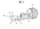
- Figure 4 is a perspective view for explanation of a mounted state of a communication module included in the lighting apparatus according to an embodiment of the present disclosure
- Figure 5 is a perspective view showing a lighting apparatus according to another embodiment of the present disclosure.
- Figure 6 is a perspective view showing a lighting apparatus according to a further embodiment of the present disclosure.
- Figure 7 is a perspective view showing the communication module included in the lighting apparatus according to an embodiment of the present disclosure.
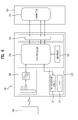
- Figure 8 is a block diagram showing a configuration of the communication module included in the lighting apparatus according to an embodiment of the present disclosure
- Figure 9 is a front view showing the communication module included in the lighting apparatus according to an embodiment of the present disclosure.
- Figure 10 is a conceptual view showing the communication module included in the lighting apparatus according to an embodiment of the present disclosure.
- light sources used primarily for lighting equipment are incandescent lamps, discharge lamps, fluorescent lamps, and the like for various purposes, such as home, landscape, industrial use, and the like.
- a resistive light source such as, for example, an incandescent lamp
- a discharge lamp has high price and high voltage problems
- a fluorescent lamp entails an environmental problem due to use of mercury.
- LEDs Light Emitting Diode
- LEDs are semiconductor devices that emit light when a forward voltage is applied thereto, and have an extended lifespan, low power consumption as well as electrical, optical, and physical characteristics suitable for mass production. Incandescent lamps and fluorescent lamps are quickly being replaced by LEDs.
- Large buildings may be equipped with a plurality of LED lighting apparatuses and a lighting control system to implement individual/group control of the LED lighting apparatuses.
- the lighting control system manages on/off states of LED lighting apparatuses installed in respective floors or particular zones, state information or power usage of each LED lighting apparatus, and the like, in real time to detect unnecessary energy use, thus minimizing energy waste.
- the lighting control system may include a controller that may control a plurality of LED lighting apparatuses in order to take charge in maintenance of building facilities, repair/maintenance of operational facilities, maintenance of a lighting environment inside a building, and management of energy to be consumed during such maintenance work.
- a plurality of LED lighting apparatuses may be individually connected to the controller in a wired communication manner, thus necessitating a complex wiring process.
- use of existing wiring may be difficult, and thus additional wiring may be necessary causing increased costs and complexity in installation.
- the present disclosure is directed to a lighting apparatus that substantially obviates one or more problems due to limitations and disadvantages of the related art.
- An object of the present disclosure is to provide a lighting apparatus that may embody a lighting control system to achieve easy individual/group control in a wireless manner without an additional wiring process.
- An object of the present disclosure is to provide a lighting apparatus to which a separate wireless communication module may be separably coupled.
- Another object of the present disclosure is to provide a lighting apparatus that enables control of on/off, dimming, or color temperature thereof in a wireless manner.
- Another object of the present disclosure is to provide a lighting apparatus that may enhance heat radiation performance.
- a further object of the present disclosure is to provide a lighting apparatus that enables simplified assembly and installation as well as easy repair and replacement.
- the lighting apparatus according to the present disclosure may be a bulb type lighting apparatus, or a Parabolic Aluminized Reflector (PAR) type lighting apparatus.
- the lighting apparatus according to an embodiment of the present disclosure may include a heat sink, and a light emitting unit which includes a substrate mounted on the heat sink and LEDs arranged on the substrate.
- the lighting apparatus may include a bulb surrounding the light emitting unit, an electronic modulewhich is received within the heat sink to supply power to the light emitting unit, and a case (or housing or enclosure) which is configured to surround the electronic moduleand inserted into the heat sink.
- the lighting apparatus may include a communication module separably coupled to the electric unit, and a power socket electrically connected to the electric unit, the power socket being mounted to the case.
- the communication module may include a housing, a circuit board which is placed in the housing and electrically connected to the electric unit, and a wireless communication unit provided on the circuit board.
- Figure 1 is a perspective view showing a lighting apparatus according to an embodiment of the present disclosure
- Figure 2 is an exploded perspective view showing the lighting apparatus
- Figure 3 is a perspective view showing main components of the lighting apparatus
- Figure 4 is a perspective view that illustrates a mounted state of a communication module included in the lighting apparatus according to an embodiment of the present disclosure.
- the lighting apparatus may be equipped with a communication module 200 which receives a control signal for the lighting apparatus 100 and transmits a signal indicating an operating state of the lighting apparatus 100.
- the communication module 200 may beseparably coupled to the lighting apparatus 100 for easy repair and replacement.
- the communication module 200 may include a wireless communication unit for wireless communication with a terminal (see, for example, terminal 300 of Figure 8) that controls the lighting apparatus 100.
- the communication module 200 may receive a control signal for the lighting apparatus 100 that is transmitted from the terminal 300. In addition, the communication module 200 may transmit a signal indicating an operating state of the lighting apparatus 100 to the terminal 300. A user may control, for example, on/off states, dimming, and/or color temperature of the lighting apparatus 100 via the terminal 300. In addition, the user may monitor an operating state of the lighting apparatus 100 via the terminal 300.
- An electronic module180 may serve to supply power to a light emitting unit 120.
- the electronic module180 may control an operating state of the light emitting unit 120.
- the communication module 200 may beelectrically connected to the electronic module180.
- a heat sink 110 may be provided to outwardly radiate heat generated by the light emitting unit 120.
- the heat sink 110 may be formed of a highly thermally conductive metal or resin material.
- the heat sink 110 may be provided with a plurality of heat radiating fins 111 to increase a heat exchange area with outside air.
- the heat sink 110 may approximately take the form of a longitudinally extending cylinder, and may internally define an empty space (or cavity) for insertion of a case 140.
- the heat sink 110 may have a first surfaceon which the light emitting unit 120 is disposed, and a second surfaceopposite to the first surface, atwhich the case 140 is inserted.
- the first surface may be a top surface of the light emitting unit 120 and the second surface may be an inner surface in the cavity.
- the electronic module180 may include a power supply to supply power to the light emitting unit 120, and a variety of circuits to control an operating state of the light emitting unit 120.
- the communication module 200 may beelectrically connected to the electronic module180.
- the case 140 may beequipped with a power socket 150 that is electrically connected to the electronic module180.
- the communication module 200 may be separably coupled to the lighting apparatus 100 in various ways to be removable.
- the communication module 200 may be connected to the electronic module180 through the bulb 130.
- the bulb 130 may have an aperture 161
- the communication module 200 may be connected to the electronic module180 through the aperture 161 of the bulb 130.
- the connector 181 of the electronic module180 may be positioned to face the aperture 161 of the bulb 130.
- the lighting apparatus 100 may further include a mounting member 171 that extends from the heat sink 110 to the aperture 161 of the bulb 130.
- the mounting member may provide support for a connector as well as being an auxiliary heat sink.
- a housing 201 of the communication module 200 may pass through the aperture 161 to thereby be inserted into the mounting member 171.
- the mounting member 171 may take the form of a hollow tubular member for insertion of the communication module 200.
- a plurality of light emitting units 120 may be radially arranged about the mounting member 171.
- the electronic module180 which may be encased by the case 140, may be inserted into the heat sink 110. Once the housing 201 has been inserted into the mounting member 171, the circuit board 202 of the communication module 200 may be inserted into the connector 181 of the electronic module180.
- the mounting member 171 may be formed of a highly thermally conductive metal material.
- the mounting member 171 may be provided with a plurality of heat radiating fins 172.
- the mounting member 171 and the heat radiating fins 172 may function as an auxiliary heat sink 170.
- the heat radiating fins 172 may each have a ramped reflective surface 172a that is inclined away from the mounting member 171 with decreasing distance to the aperture 161 of the bulb 130.
- the reflective surface 172a may function to reflect light emitted by the light emitting unit 120, for example, toward the heat sink 110.
- the case 140 may include a connector 141 thatextends to the mounting member 171.
- the housing 201 of the communication module 200 may pass through the aperture 161 of the bulb 130 to thereby be inserted into the connector 141.
- the connector 141 may be formed of a resin material, similar to the case 140.
- the connector 141 may function to insulate the mounting member 171 and the communication module 200. That is, the connector 141 may prevent transfer of heat to the communication module 200 through the mounting member 171 and may also be referred to herein as a shield member 141.
- the communication module 200 may pass through the aperture 131 of the reflective member 160 to thereby be mounted to the electronic module180. More specifically, the communication module 200 may pass through the aperture 131 of the reflective member 160 and opening 161 to thereby be inserted into the shield member 141.
- Figure 5 is a perspective view showing a lighting apparatus according to another embodiment of the present disclosure.Although a configuration for a connection between the communication module 200 and the electronic module180 through the bulb 130 has been described heretofore, the present disclosure is not limited thereto, and the communication module 200 may be connected to the electronic module180 through the heat sink 110.
- the heat sink 110 may have an aperture 112, and the communication module 200 may be mounted to the electronic module180 through the aperture 112.
- the aperture 112 may be perforated in a specific region of the heat sink 110, and the connector 181 may be positioned to face the aperture 112 of the heat sink 110.
- both the heat sink 110 and the case 140 may be provided respectively with apertures that correspond in position to each other, and the communication module 200 may pass through these apertures to thereby be mounted to the electronic module180.
- the lighting apparatus may include the heat sink 110 having the aperture 112, and the electronic module180 which is received within the heat sink 110 to supply power to the light emitting unit 120.
- the power socket 150 may be mounted to the heat sink 110.
- the heat sink 110 may be provided with a mounting portion to which the power socket 150 is mounted.
- the mounting portion may have helical threads.
- the heat sink 110 may be formed of a highly thermally conductive resin material. If the electronic module180 is directly inserted into the heat sink 110 without the case 140, insulation between the electronic module180 and the heat sink 110 is important. To this end, the heat sink 110 may be formed of a resin material.
- the heat sink 110 may contain a guide rail, and the electronic module180 may be inserted into the heat sink 110 along the guide rail.
- the electronic module180 may be supported by the guide rail.
- the guide rail may be formed at an inner surface of the heat sink 110 defining an inner space (i.e., the aforementioned empty space), and as necessary a plurality of guide rails may be provided.
- the guide rail may extend, by a predetermined length, in a longitudinal direction of the heat sink 110.
- a partial region of the circuit board of the electronic module180 may be located inside the guide rail.
- the electronic module180 When it is attempted to separate the power socket 150 from the heat sink 110, the electronic module180 may be separated from the heat sink 110. In this case, the electronic module180 may slide outward from the heat sink 110 along the guide rail.
- the communication module 200 may include the housing 201, the circuit board 202 which is placed in the housing 201 and electrically connected to the electronic module180, and the wireless communication unit provided on the circuit board 202.
- the electronic module180 may include the connector 181.
- the circuit board 202 of the communication module 200 may be inserted into the connector 181 through the aperture 112 of the heat sink 110.
- the communication module 200 may be selectively connected to the electronic module180 through the bulb 130 or the heat sink 110.
- the lighting apparatus 100 may include the heat sink 110 having a first aperture 112, and the light emitting unit 120 which includes the substrate 121 mounted on the heat sink 110 and the LEDs 122 arranged on the substrate 121.
- the lighting apparatus 100 may include the bulb 130 surrounding the light emitting unit 120, the bulb 130 having a second aperture 161, the electronic module180 received within the heat sink 110 to supply power to the light emitting unit 120, and the case 140 which is configured to surround the electronic module180 and inserted into the heat sink 110.
- the lighting apparatus 100 may include the communication module 200 separably coupled to the electronic module180 through the first aperture 112 or the second aperture 161, and the power socket 150 which is electrically connected to the electronic module180 and mounted to the case 140.
- the electronic module180 may include a first connector positioned to face the first aperture 112 and a second connector (see Figure 4 ) positioned to face the second aperture 161.
- the circuit board 202 of the communication module 200 may pass through the first aperture 112 or the second aperture 161 to thereby be inserted into the first connector or the second connector.
- the bulb type lighting apparatus 100 has been described heretofore, but the present disclosure is not limited thereto and may be applied to a PAR type lighting apparatus.
- Figure 6 is a perspective view showing a lighting apparatus according to a further embodiment of the present disclosure.
- the PAR type lighting apparatus may have a conventionally used known configuration, and Figure 6 shows only some components.
- the PAR type lighting apparatus designated by reference numeral 400, may include a heat sink 410, and a light emitting unit which may include a substrate placed in the heat sink 410 and LEDs arranged on the substrate.
- the lighting apparatus 400 may include a semispherical reflective member 460 mounted to the heat sink 110, and a case 440 mounted to the heat sink 410.
- the lighting apparatus 400 may include an electronic module480 which is placed in the case 440 to supply power to the light emitting unit, and a power socket 450 mounted to the case 440.
- a cover 430 may be mounted on the reflective member 460.
- the cover 430 may include a micro-lens array or a transparent plate.
- the communication module 200 may pass through the cover 430 to thereby be connected to the electronic module480.
- the housing of the communication module 200 may be separably coupled to the cover 430.
- the cover 430 may have a through-hole 431.
- the mounting member for example, mounting member 171 of Figure 2
- the shield member for example, shield member 141 of Figure 2 for insertion of the communication module 200 may be applied to the PAR type lighting apparatus 400.
- Figure 7 is a perspective view showing the communication module included in the lighting apparatus according to an embodiment of the present disclosure
- Figure 8 is a block diagram showing a configuration of the communication module included in the lighting apparatus according to an embodiment of the present disclosure
- Figure 9 is a front view showing the communication module included in the lighting apparatus according to an embodiment of the present disclosure
- Figure 10 is a conceptual view showing the communication module included in the lighting apparatus according to an embodiment of the present disclosure.
- a plurality of circuits to implement various functions may be mounted on the circuit board 202.
- an initialization circuit 223 and a memory 250 may be provided.
- a partial region of the circuit board 202 may protrude outward from the housing 201 in order to be inserted into the connector 181 of the electronic module180.
- the circuit board 202 may beprovided at a partial region thereof with a plurality of pins including pins to receive power from the connector 181, ground pins, and data transmission/reception pins.
- the operating state display unit 210 may include a light source (221, for example, LEDs) arranged on the circuit board 202, and a button 225 exposed outwardly from the housing 201. Moreover, theoperating state display unit 210 may further include a light guide member 224 to guide light, emitted by the light source 221, to the button 225, and a switch 226 to sense movement of the light guide member 224.
- a light source for example, LEDs
- the operating state display unit 210 may further include a light guide member 224 to guide light, emitted by the light source 221, to the button 225, and a switch 226 to sense movement of the light guide member 224.
- the light guide member 224 and the button 225 may be formed of a transparent material. In this case, if the light source 221 is operated, light emitted by the light source 221 may bedischarged outwardly along the light guide member 224 and the button 225.
- the controller 230 may display an operating state of the communication module 200, for example, by a flickering period of the light source 221.
- the flickering period may be lighting of the light source 221 according to a prescribed pattern.
- the user may confirm an operating state of the communication module 200 by monitoring the flickering of the light source 221 according to a predetermined rule.
- the operating state of the communication module 200 may include an initialization state, a data reception state, or a normal operating state.
- the light guide member 224 may slide toward the switch 226. More specifically, if the user pushes the button 225 exposed outwardly from the housing 201, the light guide member 224 may slide toward the switch 226.
- the controller 230 may proceed with initialization of the communication module 200 by judging a patterninwhich the light guide member 224 pushes the switch 226. For example, the pattern of presses may be based on a time period, number of presses, or the like.
- Initialization of the communication module 200 may includeinitialization of software to drive the controller 230 of the communication module 200.As described above, the circuit board 202 may beprovided with the initialization circuit 223, to allow the user to directly proceed with initialization of the communication module 200 by pushing the button 225, or to proceed with initialization of the communication module 200 via the terminal 300.
- the controller 230 may switch between operating modes of the communication module 200 or proceed with initialization of the communication module 200 based on pattern in which the guide member 224 is caused to activate the switch 226 (e.g., based on a time period). For instance, if the light guide member 224 pushes the switch 226 for a time period of 1 second or less, operating modes of the communication module 200 may be switched. If the light guide member 224 pushes the switch 226 for a time period of 3 seconds or more, initialization of the communication module 200 may proceed.
- the operating modes of the communication module 200 may include Pulse Width Modulation (PWM) and Universal Asynchronous Receiver/Transmitter (UART) modes. Additionally, on/off control, dimming control, or color temperature conversion of the lighting apparatus 100 are possible via PWM or UART communication.
- thewireless communication unit 240 may include a ZigBee, Wi-Fi, Bluetooth, Z-wave unit, or another appropriate means of communication. The communication module 200 may be in wireless communication with the terminal 300 that controls the lighting apparatus 100.
- a lighting apparatus may embody a lighting control system to achieve easy individual/group control in a wireless manner that does not require additional wiring at the installation site.
- a separate wireless communication module may be separably coupled to the lighting apparatus, and thus on/off state, dimming, or color temperature of a lighting apparatus may be controlled in a wireless manner.
- a lighting apparatus may achieve enhanced heat radiation performance, simplified assembly and installation as well as easy repair and replacement.
- a lighting apparatus may include a heat sink having a first aperture, a light emitting unit including a substrate mounted on the heat sink and LEDs arranged on the substrate, a bulb surrounding the light emitting unit, the bulb having a second aperture, an electronic modulereceived within the heat sink to supply power to the light emitting unit, a case configured to surround the electric unit, the case being inserted into the heat sink, a communication module separably coupled to the electronic modulethrough the first aperture or the second aperture, and a power socket electrically connected to the electric unit, the power socket being mounted to the case, wherein the communication module includes a housing, a circuit board placed in the housing, the circuit board being electrically connected to the electric unit, and a wireless communication unit provided on the circuit board.
- a lighting apparatus may include a heat sink, a light emitting device including a substrate mounted on the heat sink and LEDs arranged on the substrate, a bulb surrounding the light emitting device, an electronic module received within the heat sink to supply power to the light emitting device, a case provided to surround the electronic module, the case being configured to be insertedinto the heat sink, a communication module separably coupled to the electronic module and a power socket electrically connected to the electronic module, the power socket being mounted to the casewherein the communication module includes a housing, a circuit board provided in the housing, the circuit board being electrically connected to the electronic module, and a wireless communication device provided on the circuit board.
- An aperture may be formed on a surface of the heat sink and the communication module may be configured to be coupled to the electronic module through the aperture. Further, an aperture may be formed on a surface of the case, the aperture on the case provided to correspond to the aperture on the heat sink, and the communication module is coupled to the electronic module through the apertures.
- the bulb may be provided on a top surface of the heat sink and the aperture on the heat sink may be provided on a lateral surface of the heat sink.
- the lighting apparatus may also include a bulb that has an aperture and the communication module may becoupled to the electronic module through the aperture on the bulb.
- the heat sink may have an aperture formed on a top surface of the heat sink and positioned to correspond to the aperture on the bulb, the communication module being configured to be coupled to the electronic module through the aperture on the bulb and aperture on the heat sink.
- An auxiliary heat sink may be provided around a circumference of the aperture of the heat sink, the auxiliary heat sink protruding from the top surface of the heat sink.
- the lighting apparatus may include a casewith a connectorconfigured to extend through the aperture on the heat sink and provided adjacent the auxiliary heat sink and the housing of the communication module may be configured to be provided through the aperture of the bulb and inserted into the connector on the case.
- the housing of the communication module may beseparably coupled to the connector on the case.
- the light emitting unit may be radially arranged about the auxiliary heat sink.
- the heat sink may have a second aperture and the communication module may beconfigured to be coupled to the electronic module through the second aperture on the heat sink.
- the electronic module may include a first connector positioned to correspond to the aperture in the bulb and a second connector positioned to correspond to the second aperture in the heat sink.
- the circuit board of the communication module may beconfigured to be inserted into the first connector or the second connector through the aperture in the bulb or the second aperture in the heat sink.
- the bulb may include a reflector and the aperture on the bulb may be provided through the reflector.
- the reflector may be configured to reflect light emitted by the light emitting device toward the heat sink.
- the bulb may also include a through-hole and the reflective member that includes the aperture may be provided over the through-hole.
- the communication module may include a display interface configured to display an operating state.
- the display interface may include a light source mounted on the circuit board, a light guide provided at the light source, a button coupled to the light guide and provided on the housing, and a switch coupled to the light guide.
- the light guide may be configured to guide light emitted by the light source to the button and to activate the switch based on a selection of the button.
- the display interface may display an operating state of the communication module by illuminating the light source according to a prescribed pattern.
- the operating state of the communication module may include at least one of an initialization state, a data reception state, or a normal operating state.
- the light guide may beconfigured to move toward the switch based on selection of the button and the communication module may be initialized based on a selection at the button.
- a lighting apparatus may include a heat sink having a first aperture, a light emitting device including a substrate mounted on the heat sink and LEDs arranged on the substrate, a bulb surrounding the light emitting device, the bulb having a second aperture, an electronic modulereceived within the heat sink to supply power to the light emitting device, a case provided to surround the electronic module, the case being configured to be insertedinto the heat sink, a communication module separably coupled to the electronic modulethrough the first aperture or the second aperture, anda power socket electrically connected to the electronic module, the power socket being mounted to the case.
- the communication module may include a housing, a circuit board provided in the housing, the circuit board being electrically connected to the electronic module, and a wireless communication device provided on the circuit board.
- a communication module for a lighting apparatus may include a housing, a circuit board provided in the housing, and a wireless communication device provided on the circuit board and configured to communicate with an external device to control an operation of a lighting apparatus.
- the housing may have a prescribed shape and may be configured to be separably coupled to a connector provided on an electronic module of the lighting apparatus, the connector being provided at an aperture formed through a surface of a heat sink of the light emitting device such that the housing is mated with the connector through the surface of the heat sink.
- the aperture may be provided on at least one of an upper surface of the heat sink or a lateral surface of the heat sink.
- any reference in this specification to "one embodiment,” “an embodiment,” “example embodiment,” etc. means that a particular feature, structure, or characteristic described in connection with the embodiment is included in at least one embodiment of the invention.
- the appearances of such phrases in various places in the specification are not necessarily all referring to the same embodiment.
Landscapes
- Engineering & Computer Science (AREA)
- General Engineering & Computer Science (AREA)
- Microelectronics & Electronic Packaging (AREA)
- Physics & Mathematics (AREA)
- Optics & Photonics (AREA)
- Arrangement Of Elements, Cooling, Sealing, Or The Like Of Lighting Devices (AREA)
- Non-Portable Lighting Devices Or Systems Thereof (AREA)
- Circuit Arrangement For Electric Light Sources In General (AREA)
Applications Claiming Priority (1)
| Application Number | Priority Date | Filing Date | Title |
|---|---|---|---|
| KR1020120127254A KR102015911B1 (ko) | 2012-11-12 | 2012-11-12 | 조명장치 |
Publications (2)
| Publication Number | Publication Date |
|---|---|
| EP2730833A1 true EP2730833A1 (fr) | 2014-05-14 |
| EP2730833B1 EP2730833B1 (fr) | 2014-11-26 |
Family
ID=49551544
Family Applications (1)
| Application Number | Title | Priority Date | Filing Date |
|---|---|---|---|
| EP13192110.8A Not-in-force EP2730833B1 (fr) | 2012-11-12 | 2013-11-08 | Appareil d'éclairage |
Country Status (4)
| Country | Link |
|---|---|
| US (2) | US9651241B2 (fr) |
| EP (1) | EP2730833B1 (fr) |
| KR (1) | KR102015911B1 (fr) |
| ES (1) | ES2527851T3 (fr) |
Cited By (7)
| Publication number | Priority date | Publication date | Assignee | Title |
|---|---|---|---|---|
| GB2526440A (en) * | 2014-05-22 | 2015-11-25 | Gooee Ltd | Sensor arrangements |
| CN105299483A (zh) * | 2015-11-10 | 2016-02-03 | 德清明裕照明电器有限公司 | 一种耐高温可调节式灯泡 |
| CN105517273A (zh) * | 2014-12-18 | 2016-04-20 | 马鞍山拓普利光电科技有限公司 | 一种rf调光调色的灯具控制系统及其控制方法 |
| WO2016112815A1 (fr) * | 2015-01-13 | 2016-07-21 | Sengled Optoelectronics Co., Ltd | Procédé de réglage de niveau de luminosité, dispositif d'éclairage à del, et système d'éclairage |
| EP3139086A1 (fr) * | 2015-09-01 | 2017-03-08 | Philips Lighting Holding B.V. | Dispositif d'éclairage avec une antenne de communication sans fil |
| WO2018029067A1 (fr) * | 2016-08-12 | 2018-02-15 | Philips Lighting Holding B.V. | Dispositif d'éclairage à rééquipement de del comprenant un module de commande amovible |
| US10274137B1 (en) | 2017-11-22 | 2019-04-30 | Beautiful Light Technology Corp. | Lamp assembly and lamp using the lamp assembly |
Families Citing this family (15)
| Publication number | Priority date | Publication date | Assignee | Title |
|---|---|---|---|---|
| US9429517B2 (en) * | 2011-08-30 | 2016-08-30 | Kaipo Chen | Lighting device with expanded detection range |
| US9571712B2 (en) * | 2011-08-30 | 2017-02-14 | Kaipo Chen | Modularized lighting device |
| EP3368817B1 (fr) * | 2015-10-26 | 2019-05-08 | Signify Holding B.V. | Dispositif d'éclairage avec connecteur pour dispositif électrique complémentaire |
| US20190154244A1 (en) * | 2016-08-12 | 2019-05-23 | Philips Lighting Holding B.V. | Led-retrofit lighting device having detachable control module |
| WO2018204485A1 (fr) * | 2017-05-05 | 2018-11-08 | Hubbell Incorporated | Luminaire de grande hauteur à luminosité élevée |
| JP6879047B2 (ja) * | 2017-05-16 | 2021-06-02 | 三菱電機株式会社 | 照明器具および照明システム |
| CN108826165A (zh) * | 2018-08-03 | 2018-11-16 | 深圳市冠科科技有限公司 | 一种带可插拔控制接口的灯具 |
| CN109578955A (zh) * | 2018-12-20 | 2019-04-05 | 深圳市思坎普科技有限公司 | 一种中置感应器的照明灯 |
| CN209130543U (zh) * | 2018-11-13 | 2019-07-19 | 漳州立达信光电子科技有限公司 | 一种智能灯 |
| CN109556097A (zh) * | 2018-12-07 | 2019-04-02 | 深圳市冠科科技有限公司 | 一种感应元件及可调插拔控制接口装置 |
| CN209672089U (zh) * | 2019-03-07 | 2019-11-22 | 厦门赢科光电有限公司 | 一种智能灯 |
| US10935228B2 (en) * | 2019-04-03 | 2021-03-02 | Lutron Technology Company Llc | Wireless controllable lighting device |
| KR102307461B1 (ko) * | 2021-06-14 | 2021-09-30 | 대한라이팅 주식회사 | 등기구용 엘이디조명장치 |
| US20230375153A1 (en) * | 2021-11-24 | 2023-11-23 | Archangel Device Llc | System and method for portable, safety lighting |
| CN115002964A (zh) * | 2022-06-14 | 2022-09-02 | 东莞市英耀灯饰有限公司 | 一种用于led灯的外接式控制模组 |
Citations (8)
| Publication number | Priority date | Publication date | Assignee | Title |
|---|---|---|---|---|
| US20020048169A1 (en) * | 1997-08-26 | 2002-04-25 | Dowling Kevin J. | Light-emitting diode based products |
| WO2009103587A1 (fr) * | 2008-02-20 | 2009-08-27 | Osram Gesellschaft mit beschränkter Haftung | Ballast électronique gradable sans fil et lampe fluorescente compacte comprenant ledit ballast |
| KR20100018893A (ko) * | 2008-08-07 | 2010-02-18 | 주식회사 엠에스엠텍 | 제어기능을 갖는 형광등형 엘이디 전등 및 형광등형 엘이디전등 제어시스템 |
| US20100118148A1 (en) * | 2008-11-11 | 2010-05-13 | Young Hwan Lee | Illumination Apparatus |
| US20110134634A1 (en) * | 2009-12-09 | 2011-06-09 | Tyco Electronics Corporation | Solid state lighting assembly |
| US20120026740A1 (en) * | 2011-05-02 | 2012-02-02 | Kyunghyun Kim | Lighting apparatus |
| AU2012101135A4 (en) * | 2011-08-05 | 2012-08-30 | Qbas Tech. Co., Ltd. | Power device of LED lighting module |
| US20120274208A1 (en) * | 2009-06-05 | 2012-11-01 | Koninklijke Philips Electronics N.V. | Lighting device with built-in rf antenna |
Family Cites Families (15)
| Publication number | Priority date | Publication date | Assignee | Title |
|---|---|---|---|---|
| JP2004055473A (ja) * | 2002-07-23 | 2004-02-19 | Toshiba Lighting & Technology Corp | ワイヤレスリモコンアダプタ、電気装置および照明装置 |
| US7476002B2 (en) * | 2003-07-02 | 2009-01-13 | S.C. Johnson & Son, Inc. | Color changing light devices with active ingredient and sound emission for mood enhancement |
| TWM247772U (en) * | 2003-12-26 | 2004-10-21 | Mu-Chin You | LED luminary with remote controller |
| KR200446078Y1 (ko) * | 2007-07-10 | 2009-09-30 | (주)월드라이팅 | 무선 자동점멸기, 안정기 및 누전차단기의 일체형보안등기구 |
| JP2011228130A (ja) * | 2010-04-20 | 2011-11-10 | Fujikom Corp | Led電球 |
| CN102444790B (zh) * | 2010-09-30 | 2014-11-19 | 光宝电子(广州)有限公司 | 灯具 |
| JP2014518433A (ja) | 2011-06-14 | 2014-07-28 | 東莞巨揚電器有限公司 | 組立て式照明装置 |
| US20130051003A1 (en) * | 2011-08-26 | 2013-02-28 | Chenjun Fan | LED Lighting Device with Efficient Heat Removal |
| KR101315700B1 (ko) | 2011-09-08 | 2013-10-10 | 엘지이노텍 주식회사 | 조명 장치 |
| US9212801B2 (en) | 2011-11-23 | 2015-12-15 | Huizhou Light Engine Ltd. | Electrical connections for a light-emitting diode lamp |
| US8777443B2 (en) * | 2011-12-13 | 2014-07-15 | Kuo-Fu Yang | Split type LED lamp |
| JP2013145634A (ja) * | 2012-01-13 | 2013-07-25 | Sony Corp | 電球型光源装置 |
| US9644814B2 (en) * | 2012-05-03 | 2017-05-09 | Lighting Science Group Corporation | Luminaire with prismatic optic |
| US8926131B2 (en) | 2012-05-08 | 2015-01-06 | 3M Innovative Properties Company | Solid state light with aligned light guide and integrated vented thermal guide |
| CN202868630U (zh) | 2012-09-29 | 2013-04-10 | 东莞巨扬电器有限公司 | 散热模块及具有散热模块的组合式照明装置 |
-
2012
- 2012-11-12 KR KR1020120127254A patent/KR102015911B1/ko not_active Expired - Fee Related
-
2013
- 2013-11-08 US US14/074,953 patent/US9651241B2/en not_active Expired - Fee Related
- 2013-11-08 EP EP13192110.8A patent/EP2730833B1/fr not_active Not-in-force
- 2013-11-08 ES ES13192110.8T patent/ES2527851T3/es active Active
-
2014
- 2014-05-30 US US14/292,704 patent/US9039243B2/en active Active
Patent Citations (8)
| Publication number | Priority date | Publication date | Assignee | Title |
|---|---|---|---|---|
| US20020048169A1 (en) * | 1997-08-26 | 2002-04-25 | Dowling Kevin J. | Light-emitting diode based products |
| WO2009103587A1 (fr) * | 2008-02-20 | 2009-08-27 | Osram Gesellschaft mit beschränkter Haftung | Ballast électronique gradable sans fil et lampe fluorescente compacte comprenant ledit ballast |
| KR20100018893A (ko) * | 2008-08-07 | 2010-02-18 | 주식회사 엠에스엠텍 | 제어기능을 갖는 형광등형 엘이디 전등 및 형광등형 엘이디전등 제어시스템 |
| US20100118148A1 (en) * | 2008-11-11 | 2010-05-13 | Young Hwan Lee | Illumination Apparatus |
| US20120274208A1 (en) * | 2009-06-05 | 2012-11-01 | Koninklijke Philips Electronics N.V. | Lighting device with built-in rf antenna |
| US20110134634A1 (en) * | 2009-12-09 | 2011-06-09 | Tyco Electronics Corporation | Solid state lighting assembly |
| US20120026740A1 (en) * | 2011-05-02 | 2012-02-02 | Kyunghyun Kim | Lighting apparatus |
| AU2012101135A4 (en) * | 2011-08-05 | 2012-08-30 | Qbas Tech. Co., Ltd. | Power device of LED lighting module |
Cited By (17)
| Publication number | Priority date | Publication date | Assignee | Title |
|---|---|---|---|---|
| GB2526440B (en) * | 2014-05-22 | 2018-03-21 | Gooee Ltd | Sensor arrangements |
| CN105114830A (zh) * | 2014-05-22 | 2015-12-02 | 古伊有限公司 | 传感器装置 |
| AU2015202768B2 (en) * | 2014-05-22 | 2019-02-07 | Gooee Limited | Sensor Arrangements |
| GB2526440A (en) * | 2014-05-22 | 2015-11-25 | Gooee Ltd | Sensor arrangements |
| CN105114830B (zh) * | 2014-05-22 | 2018-10-26 | 古伊有限公司 | 传感器装置 |
| CN105517273A (zh) * | 2014-12-18 | 2016-04-20 | 马鞍山拓普利光电科技有限公司 | 一种rf调光调色的灯具控制系统及其控制方法 |
| WO2016112815A1 (fr) * | 2015-01-13 | 2016-07-21 | Sengled Optoelectronics Co., Ltd | Procédé de réglage de niveau de luminosité, dispositif d'éclairage à del, et système d'éclairage |
| WO2017036733A1 (fr) * | 2015-09-01 | 2017-03-09 | Philips Lighting Holding B.V. | Dispositif d'éclairage à antenne de communication sans fil |
| EP3351851A1 (fr) * | 2015-09-01 | 2018-07-25 | Philips Lighting Holding B.V. | Dispositif d'éclairage avec une antenne de communication sans fil |
| EP3139086A1 (fr) * | 2015-09-01 | 2017-03-08 | Philips Lighting Holding B.V. | Dispositif d'éclairage avec une antenne de communication sans fil |
| US11175000B2 (en) | 2015-09-01 | 2021-11-16 | Signify Holding B.V. | Lighting device with a wireless communication antenna |
| US11746965B2 (en) | 2015-09-01 | 2023-09-05 | Signify Holding B.V. | Lighting device with a wireless communication antenna |
| CN105299483A (zh) * | 2015-11-10 | 2016-02-03 | 德清明裕照明电器有限公司 | 一种耐高温可调节式灯泡 |
| CN105299483B (zh) * | 2015-11-10 | 2019-03-22 | 德清明裕照明电器有限公司 | 一种耐高温可调节式灯泡 |
| WO2018029067A1 (fr) * | 2016-08-12 | 2018-02-15 | Philips Lighting Holding B.V. | Dispositif d'éclairage à rééquipement de del comprenant un module de commande amovible |
| US10274137B1 (en) | 2017-11-22 | 2019-04-30 | Beautiful Light Technology Corp. | Lamp assembly and lamp using the lamp assembly |
| EP3489579A1 (fr) * | 2017-11-22 | 2019-05-29 | Beautiful Light Technology Corp. | Ensemble lampe et lampe utilisant l'ensemble lampe |
Also Published As
| Publication number | Publication date |
|---|---|
| US9651241B2 (en) | 2017-05-16 |
| KR20140060674A (ko) | 2014-05-21 |
| KR102015911B1 (ko) | 2019-08-29 |
| US20140268833A1 (en) | 2014-09-18 |
| ES2527851T3 (es) | 2015-01-30 |
| EP2730833B1 (fr) | 2014-11-26 |
| US9039243B2 (en) | 2015-05-26 |
| US20140133154A1 (en) | 2014-05-15 |
Similar Documents
| Publication | Publication Date | Title |
|---|---|---|
| US9039243B2 (en) | Lighting apparatus | |
| JP3159179U (ja) | Led照明装置 | |
| KR101360678B1 (ko) | 조명 장치 | |
| US9404624B2 (en) | Lighting apparatus | |
| US20150289349A1 (en) | Lighting Apparatus Having Communication Module | |
| US20110019433A1 (en) | Led lighting device | |
| JP2014502413A (ja) | Led照明システム | |
| WO2014197782A1 (fr) | Luminaire à led modulaire | |
| KR20130012405A (ko) | 조명 장치 | |
| KR20120108662A (ko) | 엘이디 램프 | |
| KR102047687B1 (ko) | 통신모듈 및 이를 포함하는 조명장치 | |
| CN101986005A (zh) | 照明器具 | |
| JP4676563B1 (ja) | 照明器具一体のled照明装置。 | |
| KR101617293B1 (ko) | 조명기기 | |
| US9523481B2 (en) | LED lighting apparatus | |
| KR101241348B1 (ko) | 형광등 타입 led 조명장치 및 이를 구비한 조명시스템 | |
| KR20140132491A (ko) | 통신모듈 및 이를 포함하는 조명장치 | |
| KR101075881B1 (ko) | 엘이디 조명장치 | |
| KR101969356B1 (ko) | 조명장치 | |
| KR20140060676A (ko) | 조명장치 | |
| KR20110041989A (ko) | 조명장치 | |
| KR20140023483A (ko) | 조명 장치 | |
| KR101617296B1 (ko) | 조명기기 | |
| KR101969354B1 (ko) | 조명장치 | |
| KR101865986B1 (ko) | 조명 장치 |
Legal Events
| Date | Code | Title | Description |
|---|---|---|---|
| PUAI | Public reference made under article 153(3) epc to a published international application that has entered the european phase |
Free format text: ORIGINAL CODE: 0009012 |
|
| 17P | Request for examination filed |
Effective date: 20140331 |
|
| AK | Designated contracting states |
Kind code of ref document: A1 Designated state(s): AL AT BE BG CH CY CZ DE DK EE ES FI FR GB GR HR HU IE IS IT LI LT LU LV MC MK MT NL NO PL PT RO RS SE SI SK SM TR |
|
| AX | Request for extension of the european patent |
Extension state: BA ME |
|
| GRAP | Despatch of communication of intention to grant a patent |
Free format text: ORIGINAL CODE: EPIDOSNIGR1 |
|
| RIC1 | Information provided on ipc code assigned before grant |
Ipc: F21V 3/02 20060101ALI20140620BHEP Ipc: F21K 99/00 20100101AFI20140620BHEP Ipc: F21V 23/00 20060101ALI20140620BHEP Ipc: F21Y 101/02 20060101ALN20140620BHEP Ipc: F21V 17/00 20060101ALI20140620BHEP Ipc: F21V 23/04 20060101ALI20140620BHEP |
|
| INTG | Intention to grant announced |
Effective date: 20140710 |
|
| RAP1 | Party data changed (applicant data changed or rights of an application transferred) |
Owner name: LG ELECTRONICS INC. |
|
| GRAS | Grant fee paid |
Free format text: ORIGINAL CODE: EPIDOSNIGR3 |
|
| GRAA | (expected) grant |
Free format text: ORIGINAL CODE: 0009210 |
|
| AK | Designated contracting states |
Kind code of ref document: B1 Designated state(s): AL AT BE BG CH CY CZ DE DK EE ES FI FR GB GR HR HU IE IS IT LI LT LU LV MC MK MT NL NO PL PT RO RS SE SI SK SM TR |
|
| REG | Reference to a national code |
Ref country code: GB Ref legal event code: FG4D |
|
| REG | Reference to a national code |
Ref country code: CH Ref legal event code: EP |
|
| REG | Reference to a national code |
Ref country code: AT Ref legal event code: REF Ref document number: 698413 Country of ref document: AT Kind code of ref document: T Effective date: 20141215 |
|
| REG | Reference to a national code |
Ref country code: IE Ref legal event code: FG4D |
|
| REG | Reference to a national code |
Ref country code: DE Ref legal event code: R096 Ref document number: 602013000535 Country of ref document: DE Effective date: 20150108 |
|
| REG | Reference to a national code |
Ref country code: ES Ref legal event code: FG2A Ref document number: 2527851 Country of ref document: ES Kind code of ref document: T3 Effective date: 20150130 |
|
| REG | Reference to a national code |
Ref country code: NL Ref legal event code: VDEP Effective date: 20141126 |
|
| REG | Reference to a national code |
Ref country code: AT Ref legal event code: MK05 Ref document number: 698413 Country of ref document: AT Kind code of ref document: T Effective date: 20141126 |
|
| REG | Reference to a national code |
Ref country code: LT Ref legal event code: MG4D |
|
| PG25 | Lapsed in a contracting state [announced via postgrant information from national office to epo] |
Ref country code: LT Free format text: LAPSE BECAUSE OF FAILURE TO SUBMIT A TRANSLATION OF THE DESCRIPTION OR TO PAY THE FEE WITHIN THE PRESCRIBED TIME-LIMIT Effective date: 20141126 Ref country code: NL Free format text: LAPSE BECAUSE OF FAILURE TO SUBMIT A TRANSLATION OF THE DESCRIPTION OR TO PAY THE FEE WITHIN THE PRESCRIBED TIME-LIMIT Effective date: 20141126 Ref country code: IS Free format text: LAPSE BECAUSE OF FAILURE TO SUBMIT A TRANSLATION OF THE DESCRIPTION OR TO PAY THE FEE WITHIN THE PRESCRIBED TIME-LIMIT Effective date: 20150326 Ref country code: PT Free format text: LAPSE BECAUSE OF FAILURE TO SUBMIT A TRANSLATION OF THE DESCRIPTION OR TO PAY THE FEE WITHIN THE PRESCRIBED TIME-LIMIT Effective date: 20150326 Ref country code: NO Free format text: LAPSE BECAUSE OF FAILURE TO SUBMIT A TRANSLATION OF THE DESCRIPTION OR TO PAY THE FEE WITHIN THE PRESCRIBED TIME-LIMIT Effective date: 20150226 Ref country code: FI Free format text: LAPSE BECAUSE OF FAILURE TO SUBMIT A TRANSLATION OF THE DESCRIPTION OR TO PAY THE FEE WITHIN THE PRESCRIBED TIME-LIMIT Effective date: 20141126 |
|
| PG25 | Lapsed in a contracting state [announced via postgrant information from national office to epo] |
Ref country code: GR Free format text: LAPSE BECAUSE OF FAILURE TO SUBMIT A TRANSLATION OF THE DESCRIPTION OR TO PAY THE FEE WITHIN THE PRESCRIBED TIME-LIMIT Effective date: 20150227 Ref country code: HR Free format text: LAPSE BECAUSE OF FAILURE TO SUBMIT A TRANSLATION OF THE DESCRIPTION OR TO PAY THE FEE WITHIN THE PRESCRIBED TIME-LIMIT Effective date: 20141126 Ref country code: LV Free format text: LAPSE BECAUSE OF FAILURE TO SUBMIT A TRANSLATION OF THE DESCRIPTION OR TO PAY THE FEE WITHIN THE PRESCRIBED TIME-LIMIT Effective date: 20141126 Ref country code: AT Free format text: LAPSE BECAUSE OF FAILURE TO SUBMIT A TRANSLATION OF THE DESCRIPTION OR TO PAY THE FEE WITHIN THE PRESCRIBED TIME-LIMIT Effective date: 20141126 Ref country code: SE Free format text: LAPSE BECAUSE OF FAILURE TO SUBMIT A TRANSLATION OF THE DESCRIPTION OR TO PAY THE FEE WITHIN THE PRESCRIBED TIME-LIMIT Effective date: 20141126 Ref country code: RS Free format text: LAPSE BECAUSE OF FAILURE TO SUBMIT A TRANSLATION OF THE DESCRIPTION OR TO PAY THE FEE WITHIN THE PRESCRIBED TIME-LIMIT Effective date: 20141126 Ref country code: CY Free format text: LAPSE BECAUSE OF FAILURE TO SUBMIT A TRANSLATION OF THE DESCRIPTION OR TO PAY THE FEE WITHIN THE PRESCRIBED TIME-LIMIT Effective date: 20141126 |
|
| PG25 | Lapsed in a contracting state [announced via postgrant information from national office to epo] |
Ref country code: SK Free format text: LAPSE BECAUSE OF FAILURE TO SUBMIT A TRANSLATION OF THE DESCRIPTION OR TO PAY THE FEE WITHIN THE PRESCRIBED TIME-LIMIT Effective date: 20141126 Ref country code: EE Free format text: LAPSE BECAUSE OF FAILURE TO SUBMIT A TRANSLATION OF THE DESCRIPTION OR TO PAY THE FEE WITHIN THE PRESCRIBED TIME-LIMIT Effective date: 20141126 Ref country code: DK Free format text: LAPSE BECAUSE OF FAILURE TO SUBMIT A TRANSLATION OF THE DESCRIPTION OR TO PAY THE FEE WITHIN THE PRESCRIBED TIME-LIMIT Effective date: 20141126 Ref country code: RO Free format text: LAPSE BECAUSE OF FAILURE TO SUBMIT A TRANSLATION OF THE DESCRIPTION OR TO PAY THE FEE WITHIN THE PRESCRIBED TIME-LIMIT Effective date: 20141126 Ref country code: CZ Free format text: LAPSE BECAUSE OF FAILURE TO SUBMIT A TRANSLATION OF THE DESCRIPTION OR TO PAY THE FEE WITHIN THE PRESCRIBED TIME-LIMIT Effective date: 20141126 |
|
| REG | Reference to a national code |
Ref country code: DE Ref legal event code: R097 Ref document number: 602013000535 Country of ref document: DE |
|
| PG25 | Lapsed in a contracting state [announced via postgrant information from national office to epo] |
Ref country code: PL Free format text: LAPSE BECAUSE OF FAILURE TO SUBMIT A TRANSLATION OF THE DESCRIPTION OR TO PAY THE FEE WITHIN THE PRESCRIBED TIME-LIMIT Effective date: 20141126 |
|
| PLBE | No opposition filed within time limit |
Free format text: ORIGINAL CODE: 0009261 |
|
| STAA | Information on the status of an ep patent application or granted ep patent |
Free format text: STATUS: NO OPPOSITION FILED WITHIN TIME LIMIT |
|
| REG | Reference to a national code |
Ref country code: FR Ref legal event code: PLFP Year of fee payment: 3 |
|
| 26N | No opposition filed |
Effective date: 20150827 |
|
| PG25 | Lapsed in a contracting state [announced via postgrant information from national office to epo] |
Ref country code: IT Free format text: LAPSE BECAUSE OF FAILURE TO SUBMIT A TRANSLATION OF THE DESCRIPTION OR TO PAY THE FEE WITHIN THE PRESCRIBED TIME-LIMIT Effective date: 20141126 |
|
| PG25 | Lapsed in a contracting state [announced via postgrant information from national office to epo] |
Ref country code: SI Free format text: LAPSE BECAUSE OF FAILURE TO SUBMIT A TRANSLATION OF THE DESCRIPTION OR TO PAY THE FEE WITHIN THE PRESCRIBED TIME-LIMIT Effective date: 20141126 |
|
| PG25 | Lapsed in a contracting state [announced via postgrant information from national office to epo] |
Ref country code: LU Free format text: LAPSE BECAUSE OF FAILURE TO SUBMIT A TRANSLATION OF THE DESCRIPTION OR TO PAY THE FEE WITHIN THE PRESCRIBED TIME-LIMIT Effective date: 20151108 Ref country code: MC Free format text: LAPSE BECAUSE OF FAILURE TO SUBMIT A TRANSLATION OF THE DESCRIPTION OR TO PAY THE FEE WITHIN THE PRESCRIBED TIME-LIMIT Effective date: 20141126 |
|
| REG | Reference to a national code |
Ref country code: IE Ref legal event code: MM4A |
|
| REG | Reference to a national code |
Ref country code: FR Ref legal event code: PLFP Year of fee payment: 4 |
|
| PG25 | Lapsed in a contracting state [announced via postgrant information from national office to epo] |
Ref country code: IE Free format text: LAPSE BECAUSE OF NON-PAYMENT OF DUE FEES Effective date: 20151108 |
|
| PG25 | Lapsed in a contracting state [announced via postgrant information from national office to epo] |
Ref country code: HU Free format text: LAPSE BECAUSE OF FAILURE TO SUBMIT A TRANSLATION OF THE DESCRIPTION OR TO PAY THE FEE WITHIN THE PRESCRIBED TIME-LIMIT; INVALID AB INITIO Effective date: 20131108 Ref country code: BG Free format text: LAPSE BECAUSE OF FAILURE TO SUBMIT A TRANSLATION OF THE DESCRIPTION OR TO PAY THE FEE WITHIN THE PRESCRIBED TIME-LIMIT Effective date: 20141126 |
|
| REG | Reference to a national code |
Ref country code: CH Ref legal event code: PL |
|
| PG25 | Lapsed in a contracting state [announced via postgrant information from national office to epo] |
Ref country code: LI Free format text: LAPSE BECAUSE OF NON-PAYMENT OF DUE FEES Effective date: 20161130 Ref country code: CH Free format text: LAPSE BECAUSE OF NON-PAYMENT OF DUE FEES Effective date: 20161130 |
|
| PG25 | Lapsed in a contracting state [announced via postgrant information from national office to epo] |
Ref country code: MT Free format text: LAPSE BECAUSE OF FAILURE TO SUBMIT A TRANSLATION OF THE DESCRIPTION OR TO PAY THE FEE WITHIN THE PRESCRIBED TIME-LIMIT Effective date: 20141126 |
|
| PG25 | Lapsed in a contracting state [announced via postgrant information from national office to epo] |
Ref country code: BE Free format text: LAPSE BECAUSE OF FAILURE TO SUBMIT A TRANSLATION OF THE DESCRIPTION OR TO PAY THE FEE WITHIN THE PRESCRIBED TIME-LIMIT Effective date: 20141126 |
|
| REG | Reference to a national code |
Ref country code: FR Ref legal event code: PLFP Year of fee payment: 5 |
|
| PG25 | Lapsed in a contracting state [announced via postgrant information from national office to epo] |
Ref country code: SM Free format text: LAPSE BECAUSE OF FAILURE TO SUBMIT A TRANSLATION OF THE DESCRIPTION OR TO PAY THE FEE WITHIN THE PRESCRIBED TIME-LIMIT Effective date: 20141126 |
|
| PG25 | Lapsed in a contracting state [announced via postgrant information from national office to epo] |
Ref country code: MK Free format text: LAPSE BECAUSE OF FAILURE TO SUBMIT A TRANSLATION OF THE DESCRIPTION OR TO PAY THE FEE WITHIN THE PRESCRIBED TIME-LIMIT Effective date: 20141126 |
|
| GBPC | Gb: european patent ceased through non-payment of renewal fee |
Effective date: 20171108 |
|
| REG | Reference to a national code |
Ref country code: FR Ref legal event code: PLFP Year of fee payment: 6 |
|
| PG25 | Lapsed in a contracting state [announced via postgrant information from national office to epo] |
Ref country code: TR Free format text: LAPSE BECAUSE OF FAILURE TO SUBMIT A TRANSLATION OF THE DESCRIPTION OR TO PAY THE FEE WITHIN THE PRESCRIBED TIME-LIMIT Effective date: 20141126 Ref country code: AL Free format text: LAPSE BECAUSE OF FAILURE TO SUBMIT A TRANSLATION OF THE DESCRIPTION OR TO PAY THE FEE WITHIN THE PRESCRIBED TIME-LIMIT Effective date: 20141126 |
|
| PG25 | Lapsed in a contracting state [announced via postgrant information from national office to epo] |
Ref country code: GB Free format text: LAPSE BECAUSE OF NON-PAYMENT OF DUE FEES Effective date: 20171108 |
|
| RIC2 | Information provided on ipc code assigned after grant |
Ipc: F21V 23/04 20060101ALI20140620BHEP Ipc: F21Y 101/02 20000101ALN20140620BHEP Ipc: F21V 3/02 20060101ALI20140620BHEP Ipc: F21K 99/00 20160101AFI20140620BHEP Ipc: F21V 17/00 20060101ALI20140620BHEP Ipc: F21V 23/00 20150101ALI20140620BHEP |
|
| PGFP | Annual fee paid to national office [announced via postgrant information from national office to epo] |
Ref country code: DE Payment date: 20191004 Year of fee payment: 7 |
|
| PGFP | Annual fee paid to national office [announced via postgrant information from national office to epo] |
Ref country code: ES Payment date: 20191203 Year of fee payment: 7 Ref country code: FR Payment date: 20191008 Year of fee payment: 7 |
|
| REG | Reference to a national code |
Ref country code: DE Ref legal event code: R119 Ref document number: 602013000535 Country of ref document: DE |
|
| PG25 | Lapsed in a contracting state [announced via postgrant information from national office to epo] |
Ref country code: FR Free format text: LAPSE BECAUSE OF NON-PAYMENT OF DUE FEES Effective date: 20201130 |
|
| PG25 | Lapsed in a contracting state [announced via postgrant information from national office to epo] |
Ref country code: DE Free format text: LAPSE BECAUSE OF NON-PAYMENT OF DUE FEES Effective date: 20210601 |
|
| REG | Reference to a national code |
Ref country code: ES Ref legal event code: FD2A Effective date: 20220201 |
|
| PG25 | Lapsed in a contracting state [announced via postgrant information from national office to epo] |
Ref country code: ES Free format text: LAPSE BECAUSE OF NON-PAYMENT OF DUE FEES Effective date: 20201109 |