EP2730316A1 - Optical detector device for fire detection - Google Patents
Optical detector device for fire detection Download PDFInfo
- Publication number
- EP2730316A1 EP2730316A1 EP13005049.5A EP13005049A EP2730316A1 EP 2730316 A1 EP2730316 A1 EP 2730316A1 EP 13005049 A EP13005049 A EP 13005049A EP 2730316 A1 EP2730316 A1 EP 2730316A1
- Authority
- EP
- European Patent Office
- Prior art keywords
- optical detector
- detector device
- detectors
- individual detectors
- detection
- Prior art date
- Legal status (The legal status is an assumption and is not a legal conclusion. Google has not performed a legal analysis and makes no representation as to the accuracy of the status listed.)
- Granted
Links
- 230000003287 optical effect Effects 0.000 title claims abstract description 28
- 238000001514 detection method Methods 0.000 title claims description 23
- 238000011156 evaluation Methods 0.000 claims abstract description 9
- 230000005855 radiation Effects 0.000 claims description 11
- 238000002485 combustion reaction Methods 0.000 claims description 3
- 230000003213 activating effect Effects 0.000 claims description 2
- RKTYLMNFRDHKIL-UHFFFAOYSA-N copper;5,10,15,20-tetraphenylporphyrin-22,24-diide Chemical compound [Cu+2].C1=CC(C(=C2C=CC([N-]2)=C(C=2C=CC=CC=2)C=2C=CC(N=2)=C(C=2C=CC=CC=2)C2=CC=C3[N-]2)C=2C=CC=CC=2)=NC1=C3C1=CC=CC=C1 RKTYLMNFRDHKIL-UHFFFAOYSA-N 0.000 claims description 2
- 230000004438 eyesight Effects 0.000 abstract 2
- 238000013461 design Methods 0.000 description 2
- 238000009434 installation Methods 0.000 description 2
- 230000003595 spectral effect Effects 0.000 description 2
- 230000001629 suppression Effects 0.000 description 2
- 238000012217 deletion Methods 0.000 description 1
- 230000037430 deletion Effects 0.000 description 1
- 230000001419 dependent effect Effects 0.000 description 1
- 238000010586 diagram Methods 0.000 description 1
- 238000000034 method Methods 0.000 description 1
- 238000012544 monitoring process Methods 0.000 description 1
Images
Classifications
-
- G—PHYSICS
- G08—SIGNALLING
- G08B—SIGNALLING OR CALLING SYSTEMS; ORDER TELEGRAPHS; ALARM SYSTEMS
- G08B13/00—Burglar, theft or intruder alarms
- G08B13/18—Actuation by interference with heat, light, or radiation of shorter wavelength; Actuation by intruding sources of heat, light, or radiation of shorter wavelength
- G08B13/189—Actuation by interference with heat, light, or radiation of shorter wavelength; Actuation by intruding sources of heat, light, or radiation of shorter wavelength using passive radiation detection systems
- G08B13/19—Actuation by interference with heat, light, or radiation of shorter wavelength; Actuation by intruding sources of heat, light, or radiation of shorter wavelength using passive radiation detection systems using infrared-radiation detection systems
- G08B13/193—Actuation by interference with heat, light, or radiation of shorter wavelength; Actuation by intruding sources of heat, light, or radiation of shorter wavelength using passive radiation detection systems using infrared-radiation detection systems using focusing means
-
- G—PHYSICS
- G08—SIGNALLING
- G08B—SIGNALLING OR CALLING SYSTEMS; ORDER TELEGRAPHS; ALARM SYSTEMS
- G08B13/00—Burglar, theft or intruder alarms
- G08B13/18—Actuation by interference with heat, light, or radiation of shorter wavelength; Actuation by intruding sources of heat, light, or radiation of shorter wavelength
- G08B13/189—Actuation by interference with heat, light, or radiation of shorter wavelength; Actuation by intruding sources of heat, light, or radiation of shorter wavelength using passive radiation detection systems
- G08B13/19—Actuation by interference with heat, light, or radiation of shorter wavelength; Actuation by intruding sources of heat, light, or radiation of shorter wavelength using passive radiation detection systems using infrared-radiation detection systems
-
- G—PHYSICS
- G08—SIGNALLING
- G08B—SIGNALLING OR CALLING SYSTEMS; ORDER TELEGRAPHS; ALARM SYSTEMS
- G08B17/00—Fire alarms; Alarms responsive to explosion
- G08B17/12—Actuation by presence of radiation or particles, e.g. of infrared radiation or of ions
Definitions
- the invention relates to an optical detector device for fire detection according to the preamble of claim 1.
- optical detectors which respond to radiation emitted during combustion. Described is a fire detection measuring device of the type including a selective fire detection part for detecting at least two different spectral bands as they occur in a fire, and which generates an output signal in response to predetermined amounts of this radiation in the spectral bands, such as a certain size and type of fire to be detected.
- Systems based on optical triggering factors are commercially successful and demonstrate their utility in various military and civilian fire detection and suppression systems.
- the radiation intensity is a certain threshold must have exceeded for the optical detector to respond.
- a plurality of detectors with different fields of view are therefore arranged at a distance from one another and connected to a central evaluation unit for receiving and evaluating signals from the detectors.
- the disadvantage is that the prerequisite for the optimal function of the plurality of detectors is that the number and position of the detectors is correctly determined during installation. Only then, no matter where the fire originates, it is detected and can be deleted within a few milliseconds. In addition, interior furnishings can hinder the positioning.
- the object of the invention is therefore to provide an optical detection device for fire detection, which improves the fire detection to trigger a deletion process.
- an optical detection device for fire detection is created, which is a central unit for ceiling mounting.
- Such a design is compact and determines their arrangement to each other even before the installation of the detectors, whereby a reliable scanning of a room can be ensured.
- the plurality of detectors are assembled as individual detectors on the ceiling mount, wherein each individual detector looks in an at least slightly different direction due to the dome-shaped design of the ceiling mount.
- the centrally aligned individual detectors set from their individual Fields of view, an optical scanning of the space to be monitored together.
- the number of individual detectors and the respective position on the ceiling support can be varied. However, the arrangement is preferably rigid when fixed presets are made.
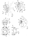
- the invention relates to an optical detection device for fire detection in a room with a plurality of optical detectors, which are arranged distributed as individual detectors 1, 2, 3, 4 on a dome-shaped ceiling mount 5, so that their fields of view 6 (see. Fig. 6 ) look in a different direction.
- the individual detectors 1, 2, 3, 4 define a number of fields of view 6, in which the space to be monitored is spatially resolved.
- the individual detectors 1, 2, 3, 4 respond to radiation emitted during combustion, each with a pair of sensors 7, 8 whose fields of view 6 are aligned differently for each partial detection of the space to be monitored, such as Fig. 6 shows.
- the individual detectors 1, 2, 3, 4 are preferably arranged rigidly. Pivoting arrangements are also possible.
- the respective sensor pair 7, 8 preferably responds to two different wavelengths in the infrared range.
- the dome-shaped ceiling holder 5 may be formed semicircular or truncated Dahlflächner.
- the ceiling holder 5 thereby has an outer surface which has curved or differently directed beveled surface sections 9, 10, 11, 12 and distributed to the individual detectors 1, 2, 3, 4 arranged distributed.
- Are filter discs 13, 14 of the individual detectors 1, 2, 3, 4 aligned to these surface portions 9, 10, 11, 12, for example, aligned flush with these, by the position of the surface portions 9, 10, 11, 12 to the perpendicular 15 and the Beam angle 16 perpendicular to the filter disk 13, 14 of the single detector 1, 2, 3, 4 are set in all directions.
- the radiation angles 16 limit viewing angle cone as a viewing cone in the range of 35 ° to 55 °, is detected in the radiation for a fire detection.
- the emission angle 16 is preferably in the range of 45 ° for a 360 ° detection of radiation, as in FIG Fig. 5 and Fig. 6 shown schematically.
- the ceiling mount 5 is formed, for example, as a tetragonal truncated pyramid, on the pyramidal frustum surfaces, which form the directed surface sections 9, 10, 11, 12, four individual detectors 1, 2, 3, 4 are arranged distributed circumferentially here.
- the ceiling holder 5 can be designed for a flush-mounted or suspended ceiling mounting and has fastening elements 17 for this purpose.
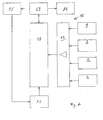
- the ceiling holder 5 preferably receives a central evaluation unit 18, as shown schematically in FIG Fig. 7 is shown.
- the individual detectors 1, 2, 3, 4 are connected to an evaluation circuit 19 which evaluates the signals detected and supplied by the individual detectors and is connected to a control device 20 for activating an extinguishing system as a function of detected signals of the individual detectors 1, 2, 3, 4 ,
- the ceiling holder 5 may have connection sockets 21, 22, as in Fig. 2 shown.
- the control device 20 may be connected in a known manner to display and adjustment elements 23, 24, 25.
- a ceiling light 26 may also be integrated, which may be switchable via the control device 20.
Abstract
Description
Die Erfindung betrifft eine optische Detektoreinrichtung zur Branderkennung nach dem Oberbegriff des Anspruchs 1.The invention relates to an optical detector device for fire detection according to the preamble of
Zum Erkennen von Bränden sind aus
Erforderlich bei solchen optischen Detektoren ist, dass die Strahlungsintensität eine bestimmte Schwelle überschritten haben muss, damit der optische Detektor anspricht. Zum Überwachen eines Raumbereiches, beispielsweise eines Fahrzeuginnenraumes, sind deshalb mehrere Detektoren mit unterschiedlichen Blickfeldern mit Abstand zueinander angeordnet und mit einer zentralen Auswerteeinheit zum Empfangen und Auswerten von Signalen der Detektoren verbunden.What is required in such optical detectors is that the radiation intensity is a certain threshold must have exceeded for the optical detector to respond. For monitoring a spatial area, for example a vehicle interior, a plurality of detectors with different fields of view are therefore arranged at a distance from one another and connected to a central evaluation unit for receiving and evaluating signals from the detectors.
Die Überlebensfähigkeit der Fahrzeuginsassen und des Fahrzeuges selber erhöhen sich. Eine frühzeitige Erkennung eines Feuers, um dieses dann automatisch löschen zu können, bietet folglich Schutz vor Brandrisiken durch eine solche Feuererfassung und Brandunterdrückung.The survivability of the vehicle occupants and the vehicle itself increase. Early detection of a fire, in order to be able to automatically extinguish it, thus provides protection against fire risks by such fire detection and fire suppression.
Nachteilig ist, dass Voraussetzung für die optimale Funktion der mehreren Detektoren ist, dass die Anzahl und Position der Detektoren beim Einbau richtig festgelegt wird. Nur dann wird, egal wo das Feuer entsteht, dieses erkannt und kann innerhalb weniger Millisekunden gelöscht werden. Zudem können Inneneinrichtungen die Positionierung behindern.The disadvantage is that the prerequisite for the optimal function of the plurality of detectors is that the number and position of the detectors is correctly determined during installation. Only then, no matter where the fire originates, it is detected and can be deleted within a few milliseconds. In addition, interior furnishings can hinder the positioning.
Aufgabe der Erfindung ist es daher, eine optische Detektoreinrichtung zur Branderkennung zu schaffen, die die Feuererfassung zum Auslösen eines Löschvorganges verbessert.The object of the invention is therefore to provide an optical detection device for fire detection, which improves the fire detection to trigger a deletion process.
Diese Aufgabe wird durch die Merkmale des Anspruchs 1 gelöst. Hierdurch wird eine optische Detektoreinrichtung zur Branderkennung geschaffen, die eine zentrale Einheit zur Deckenmontage ist. Eine derartige Ausbildung ist kompakt und legt bereits vor dem Einbau der Detektoren deren Anordnung zueinander fest, wodurch eine zuverlässige Abtastung eines Raumes sichergestellt werden kann.This object is solved by the features of
Die mehreren Detektoren sind als Einzeldetektoren an dem Deckenhalter zusammengesetzt, wobei jeder Einzeldetektor in eine zumindest geringfügig andere Richtung blickt aufgrund der kalottenförmigen Ausbildung des Deckenhalters. Die zentral zueinander ausgerichteten Einzeldetektoren setzen aus ihren einzelnen Blickfeldern ein optisches Abtastbild des zu überwachenden Raumes zusammen. Die Anzahl der Einzeldetektoren und die jeweilige Position am Deckenträger sind dazu variierbar. Die Anordnung erfolgt allerdings vorzugsweise starr, wenn feste Voreinstellungen vorgenommen werden.The plurality of detectors are assembled as individual detectors on the ceiling mount, wherein each individual detector looks in an at least slightly different direction due to the dome-shaped design of the ceiling mount. The centrally aligned individual detectors set from their individual Fields of view, an optical scanning of the space to be monitored together. The number of individual detectors and the respective position on the ceiling support can be varied. However, the arrangement is preferably rigid when fixed presets are made.
Weitere Ausgestaltungen und Vorteile der Erfindung sind der nachfolgenden Beschreibung und den Unteransprüchen zu entnehmen.Further embodiments and advantages of the invention will become apparent from the following description and the dependent claims.
Die Erfindung wird nachstehend anhand des in den beigefügten Abbildungen dargestellten Ausführungsbeispiels näher erläutert.
-
Fig. 1 zeigt schematisch eine perspektivische Ansicht einer optischen Detektoreinrichtung, -
Fig. 2 zeigt eine Kopfansicht der Detektoreinrichtung gemäßFig. 1 , -
Fig. 3 zeigt eine Vorderansicht der Detektoreinrichtung gemäßFig. 2 , -
Fig. 4 zeigt eine Seitenansicht der Detektoreinrichtung gemäßFig. 2 , -
Fig. 5 zeigt eine Ansicht A nachFig. 2 , -
Fig. 6 zeigt schematisch eine perspektivische Ansicht der optischen Detektoreinrichtung gemäßFig. 1 mit angezeigten Abstrahlwinkelkegeln, die die Blickfelder der Einzeldetektoren bestimmen, -
Fig. 7 zeigt schematisch ein Blockschaltbild einer Auswerteeinheit der Detektoreinrichtung.
-
Fig. 1 shows schematically a perspective view of an optical detector device, -
Fig. 2 shows a head view of the detector device according toFig. 1 . -
Fig. 3 shows a front view of the detector device according toFig. 2 . -
Fig. 4 shows a side view of the detector device according toFig. 2 . -
Fig. 5 shows a view A afterFig. 2 . -
Fig. 6 schematically shows a perspective view of the optical detector device according toFig. 1 with displayed beam angles, which determine the fields of view of the single detectors, -
Fig. 7 schematically shows a block diagram of an evaluation of the detector device.
Wie
Die Einzeldetektoren 1, 2, 3, 4 sprechen auf bei einer Verbrennung emittierte Strahlung mit jeweils einem Sensorpaar 7, 8 an, deren Blickfelder 6 für jeweils eine Teilerfassung des zu überwachenden Raums unterschiedlich ausgerichtet sind, wie
Der kalottenförmige Deckenhalter 5 kann halbkreisförmig oder als abgestumpfter Vielflächner ausgebildet sein. Der Deckenhalter 5 weist dadurch eine Außenfläche auf, die gekrümmte oder verschieden gerichtete abgeschrägte Flächenabschnitte 9, 10, 11, 12 aufweist und auf die Einzeldetektoren 1, 2, 3, 4 vereinzelt angeordnet verteilt sind. Sind Filterscheiben 13, 14 der Einzeldetektoren 1, 2, 3, 4 zu diesen Flächenabschnitten 9, 10, 11, 12 ausgerichtet, beispielsweise bündig zu diesen angeordnet, kann durch die Stellung der Flächenabschnitte 9, 10, 11, 12 zur Lotrechten 15 auch der Abstrahlwinkel 16 lotrecht zur Filterscheibe 13, 14 des Einzeldetektors 1, 2, 3, 4 in allen Richtungen festgelegt werden. Die Abstrahlwinkel 16 begrenzen Abstrahlwinkelkegel als Blickkegel im Bereich von 35° bis 55°, in dem Strahlung für eine Feuererfassung erfasst wird. Bevorzugt liegt der Abstrahlwinkel 16 jeweils im Bereich um 45° für eine 360° Erfassung von Strahlung, wie in
Bei dem in den
Der Deckenhalter 5 kann für eine flächenbündige oder abgehängte Deckenmontage ausgebildet sein und weist dazu Befestigungselemente 17 auf.The
Der Deckenhalter 5 nimmt vorzugsweise eine zentrale Auswerteeinheit 18 auf, wie sie schematisch in
In den Deckenhalter 5 kann zudem eine Deckenleuchte 26 integriert sein, die über die Steuereinrichtung 20 schaltbar sein kann.In the
Claims (11)
Applications Claiming Priority (1)
| Application Number | Priority Date | Filing Date | Title |
|---|---|---|---|
| DE102012022051.0A DE102012022051A1 (en) | 2012-11-09 | 2012-11-09 | Optical detector device for fire detection |
Publications (2)
| Publication Number | Publication Date |
|---|---|
| EP2730316A1 true EP2730316A1 (en) | 2014-05-14 |
| EP2730316B1 EP2730316B1 (en) | 2019-09-11 |
Family
ID=49474193
Family Applications (1)
| Application Number | Title | Priority Date | Filing Date |
|---|---|---|---|
| EP13005049.5A Active EP2730316B1 (en) | 2012-11-09 | 2013-10-22 | Optical detector device for fire detection |
Country Status (3)
| Country | Link |
|---|---|
| EP (1) | EP2730316B1 (en) |
| DE (1) | DE102012022051A1 (en) |
| ES (1) | ES2761352T3 (en) |
Cited By (3)
| Publication number | Priority date | Publication date | Assignee | Title |
|---|---|---|---|---|
| ITUB20155886A1 (en) * | 2015-11-25 | 2017-05-25 | A M General Contractor S P A | Infrared radiation fire detector with compound function for confined space. |
| CN115382131A (en) * | 2022-08-25 | 2022-11-25 | 兴数能源科技有限公司 | Fire fighting system and method for light storage micro-grid scene |
| CN115869564A (en) * | 2022-12-01 | 2023-03-31 | 南京开拓建设有限公司 | Remote safe operation and maintenance system for distribution room |
Citations (5)
| Publication number | Priority date | Publication date | Assignee | Title |
|---|---|---|---|---|
| DE2819183C2 (en) | 1977-05-20 | 1985-05-02 | Graviner Ltd., Colnbrook, Berkshire | Selective fire detection device |
| US4778996A (en) * | 1986-09-08 | 1988-10-18 | Cerberus Ag | Ceiling mounted passive infrared intrusion detector with pyramidal mirror |
| DE4200340C2 (en) | 1992-01-09 | 1995-08-24 | Kidde Deugra Brandschutzsystem | Device for selective fire detection and triggering an extinguishing process |
| DE19517517A1 (en) * | 1994-05-28 | 1995-11-30 | Cerberus Ag | Passive infrared heat sensing monitor for ceiling-mounted security system e.g. in warehouse or factory hall |
| DE202004018647U1 (en) * | 2004-12-01 | 2006-04-06 | Steinel Gmbh | SensorLight |
Family Cites Families (7)
| Publication number | Priority date | Publication date | Assignee | Title |
|---|---|---|---|---|
| DE1448585A1 (en) * | 1964-05-06 | 1969-03-27 | Frieseke & Hoepfner Gmbh | Device for determining the strength, distance and height of a nuclear explosion |
| DE4414078A1 (en) * | 1994-04-22 | 1995-10-26 | Merten Gmbh & Co Kg Geb | Infrared motion detector for mounting on wall or ceiling of building |
| DE29620405U1 (en) * | 1996-11-22 | 1997-06-19 | Merten Gmbh & Co Kg Geb | motion detector |
| DE19648466A1 (en) * | 1996-11-22 | 1998-05-28 | Merten Gmbh & Co Kg Geb | IR movement monitor with non-contact operation for securing at surface e.g. ceiling |
| DE19648468A1 (en) * | 1996-11-22 | 1998-05-28 | Merten Gmbh & Co Kg Geb | Infrared monitoring device |
| EP2093731A1 (en) * | 2008-02-19 | 2009-08-26 | Siemens Aktiengesellschaft | Linear optical smoke alarm with multiple part-beams |
| US8841617B2 (en) * | 2011-07-05 | 2014-09-23 | Honeywell International Inc. | Flame detectors and methods of detecting flames |
-
2012
- 2012-11-09 DE DE102012022051.0A patent/DE102012022051A1/en not_active Ceased
-
2013
- 2013-10-22 EP EP13005049.5A patent/EP2730316B1/en active Active
- 2013-10-22 ES ES13005049T patent/ES2761352T3/en active Active
Patent Citations (5)
| Publication number | Priority date | Publication date | Assignee | Title |
|---|---|---|---|---|
| DE2819183C2 (en) | 1977-05-20 | 1985-05-02 | Graviner Ltd., Colnbrook, Berkshire | Selective fire detection device |
| US4778996A (en) * | 1986-09-08 | 1988-10-18 | Cerberus Ag | Ceiling mounted passive infrared intrusion detector with pyramidal mirror |
| DE4200340C2 (en) | 1992-01-09 | 1995-08-24 | Kidde Deugra Brandschutzsystem | Device for selective fire detection and triggering an extinguishing process |
| DE19517517A1 (en) * | 1994-05-28 | 1995-11-30 | Cerberus Ag | Passive infrared heat sensing monitor for ceiling-mounted security system e.g. in warehouse or factory hall |
| DE202004018647U1 (en) * | 2004-12-01 | 2006-04-06 | Steinel Gmbh | SensorLight |
Cited By (8)
| Publication number | Priority date | Publication date | Assignee | Title |
|---|---|---|---|---|
| ITUB20155886A1 (en) * | 2015-11-25 | 2017-05-25 | A M General Contractor S P A | Infrared radiation fire detector with compound function for confined space. |
| EP3174022A1 (en) * | 2015-11-25 | 2017-05-31 | A.M. General Contractor S.p.A. | Infrared radiation fire detector with composite function for confined spaces |
| CN107025428A (en) * | 2015-11-25 | 2017-08-08 | A.M.总建筑股份公司 | The infra-red radiation fire detector with complex function for the confined space |
| US10255506B2 (en) | 2015-11-25 | 2019-04-09 | A.M. GENERAL CONTRACTOR S.p.A. | Infrared radiation fire detector with composite function for confined spaces |
| CN107025428B (en) * | 2015-11-25 | 2022-01-25 | A.M.总建筑股份公司 | Infrared radiation fire detector with composite function for limited space |
| CN115382131A (en) * | 2022-08-25 | 2022-11-25 | 兴数能源科技有限公司 | Fire fighting system and method for light storage micro-grid scene |
| CN115869564A (en) * | 2022-12-01 | 2023-03-31 | 南京开拓建设有限公司 | Remote safe operation and maintenance system for distribution room |
| CN115869564B (en) * | 2022-12-01 | 2024-03-15 | 南京开拓建设有限公司 | Remote safe operation and maintenance system for power distribution room |
Also Published As
| Publication number | Publication date |
|---|---|
| EP2730316B1 (en) | 2019-09-11 |
| DE102012022051A1 (en) | 2014-05-15 |
| ES2761352T3 (en) | 2020-05-19 |
Similar Documents
| Publication | Publication Date | Title |
|---|---|---|
| EP2251846B1 (en) | Fire alarm | |
| DE102009046556B4 (en) | Fire alarm device with testing device | |
| DE102010039230B3 (en) | Evaluate scattered light signals in an optical hazard detector and issue a dust / steam warning or a fire alarm | |
| EP2407949B1 (en) | Ring shaped auxiliary light source | |
| WO2009129871A1 (en) | Fire detector device and method for fire detection | |
| DE102005060748B3 (en) | Fire warning alarm unit e.g. smoke warning alarm unit, flame alarm unit for use in houses and commercial areas has memory for storing self-testing results which are also sent by transmitter to receiver | |
| EP2730316B1 (en) | Optical detector device for fire detection | |
| DE102012201589A1 (en) | Fire detector with man-machine interface as well as methods for controlling the fire detector | |
| DE102013002859A1 (en) | Fire/smoke detecting apparatus installed at ceiling/wall of room, has evaluation device that is provided to evaluate contamination on cover plate based on radiations emitted by radiation emitter and received by radiation receiver | |
| DE1578477B2 (en) | APPROXIMATE CONVERTER | |
| EP2251847B1 (en) | Device and method for detecting flames with detectors | |
| EP1407248B1 (en) | Video smoke detection system and method for examining the same | |
| DE102017111017B4 (en) | Light canopy for detecting and signaling different dangerous situations | |
| EP2759994B1 (en) | Fire alarm | |
| DE2645040C3 (en) | Radiation detector | |
| DE4040812A1 (en) | MINIATURIZED PASSIVE INFRARED MOTION DETECTOR | |
| EP2940668A2 (en) | Danger warning system | |
| DE102004034908A1 (en) | Smoke alarm system for aircraft, has camera module and smoke warning transmitter which are arranged in housing | |
| DE102019110336A1 (en) | smoke detector | |
| DE4200340C2 (en) | Device for selective fire detection and triggering an extinguishing process | |
| DE202009018974U1 (en) | Sensor for angle-resolved detection of flames or fires | |
| DE102022116321B3 (en) | smoke detector | |
| DE102017207852A1 (en) | Fire detection device for detecting a fire and / or smoke in a surveillance area | |
| EP2940665A2 (en) | Danger warning system | |
| EP0133990B1 (en) | Smoke sensor arrangement operating by the extinguish principle, and fire assembly having such a smoke sensor arrangement |
Legal Events
| Date | Code | Title | Description |
|---|---|---|---|
| PUAI | Public reference made under article 153(3) epc to a published international application that has entered the european phase |
Free format text: ORIGINAL CODE: 0009012 |
|
| 17P | Request for examination filed |
Effective date: 20131022 |
|
| AK | Designated contracting states |
Kind code of ref document: A1 Designated state(s): AL AT BE BG CH CY CZ DE DK EE ES FI FR GB GR HR HU IE IS IT LI LT LU LV MC MK MT NL NO PL PT RO RS SE SI SK SM TR |
|
| AX | Request for extension of the european patent |
Extension state: BA ME |
|
| R17P | Request for examination filed (corrected) |
Effective date: 20141114 |
|
| RBV | Designated contracting states (corrected) |
Designated state(s): AL AT BE BG CH CY CZ DE DK EE ES FI FR GB GR HR HU IE IS IT LI LT LU LV MC MK MT NL NO PL PT RO RS SE SI SK SM TR |
|
| GRAP | Despatch of communication of intention to grant a patent |
Free format text: ORIGINAL CODE: EPIDOSNIGR1 |
|
| STAA | Information on the status of an ep patent application or granted ep patent |
Free format text: STATUS: GRANT OF PATENT IS INTENDED |
|
| INTG | Intention to grant announced |
Effective date: 20180614 |
|
| GRAJ | Information related to disapproval of communication of intention to grant by the applicant or resumption of examination proceedings by the epo deleted |
Free format text: ORIGINAL CODE: EPIDOSDIGR1 |
|
| STAA | Information on the status of an ep patent application or granted ep patent |
Free format text: STATUS: REQUEST FOR EXAMINATION WAS MADE |
|
| INTC | Intention to grant announced (deleted) | ||
| GRAP | Despatch of communication of intention to grant a patent |
Free format text: ORIGINAL CODE: EPIDOSNIGR1 |
|
| STAA | Information on the status of an ep patent application or granted ep patent |
Free format text: STATUS: GRANT OF PATENT IS INTENDED |
|
| INTG | Intention to grant announced |
Effective date: 20190326 |
|
| GRAS | Grant fee paid |
Free format text: ORIGINAL CODE: EPIDOSNIGR3 |
|
| GRAA | (expected) grant |
Free format text: ORIGINAL CODE: 0009210 |
|
| STAA | Information on the status of an ep patent application or granted ep patent |
Free format text: STATUS: THE PATENT HAS BEEN GRANTED |
|
| AK | Designated contracting states |
Kind code of ref document: B1 Designated state(s): AL AT BE BG CH CY CZ DE DK EE ES FI FR GB GR HR HU IE IS IT LI LT LU LV MC MK MT NL NO PL PT RO RS SE SI SK SM TR |
|
| REG | Reference to a national code |
Ref country code: GB Ref legal event code: FG4D Free format text: NOT ENGLISH |
|
| REG | Reference to a national code |
Ref country code: CH Ref legal event code: EP |
|
| REG | Reference to a national code |
Ref country code: AT Ref legal event code: REF Ref document number: 1177704 Country of ref document: AT Kind code of ref document: T Effective date: 20190915 |
|
| REG | Reference to a national code |
Ref country code: DE Ref legal event code: R096 Ref document number: 502013013546 Country of ref document: DE Ref country code: IE Ref legal event code: FG4D Free format text: LANGUAGE OF EP DOCUMENT: GERMAN |
|
| REG | Reference to a national code |
Ref country code: NL Ref legal event code: MP Effective date: 20190911 |
|
| REG | Reference to a national code |
Ref country code: LT Ref legal event code: MG4D |
|
| PG25 | Lapsed in a contracting state [announced via postgrant information from national office to epo] |
Ref country code: LT Free format text: LAPSE BECAUSE OF FAILURE TO SUBMIT A TRANSLATION OF THE DESCRIPTION OR TO PAY THE FEE WITHIN THE PRESCRIBED TIME-LIMIT Effective date: 20190911 Ref country code: FI Free format text: LAPSE BECAUSE OF FAILURE TO SUBMIT A TRANSLATION OF THE DESCRIPTION OR TO PAY THE FEE WITHIN THE PRESCRIBED TIME-LIMIT Effective date: 20190911 Ref country code: BG Free format text: LAPSE BECAUSE OF FAILURE TO SUBMIT A TRANSLATION OF THE DESCRIPTION OR TO PAY THE FEE WITHIN THE PRESCRIBED TIME-LIMIT Effective date: 20191211 Ref country code: NO Free format text: LAPSE BECAUSE OF FAILURE TO SUBMIT A TRANSLATION OF THE DESCRIPTION OR TO PAY THE FEE WITHIN THE PRESCRIBED TIME-LIMIT Effective date: 20191211 Ref country code: SE Free format text: LAPSE BECAUSE OF FAILURE TO SUBMIT A TRANSLATION OF THE DESCRIPTION OR TO PAY THE FEE WITHIN THE PRESCRIBED TIME-LIMIT Effective date: 20190911 Ref country code: HR Free format text: LAPSE BECAUSE OF FAILURE TO SUBMIT A TRANSLATION OF THE DESCRIPTION OR TO PAY THE FEE WITHIN THE PRESCRIBED TIME-LIMIT Effective date: 20190911 |
|
| PG25 | Lapsed in a contracting state [announced via postgrant information from national office to epo] |
Ref country code: LV Free format text: LAPSE BECAUSE OF FAILURE TO SUBMIT A TRANSLATION OF THE DESCRIPTION OR TO PAY THE FEE WITHIN THE PRESCRIBED TIME-LIMIT Effective date: 20190911 Ref country code: GR Free format text: LAPSE BECAUSE OF FAILURE TO SUBMIT A TRANSLATION OF THE DESCRIPTION OR TO PAY THE FEE WITHIN THE PRESCRIBED TIME-LIMIT Effective date: 20191212 Ref country code: AL Free format text: LAPSE BECAUSE OF FAILURE TO SUBMIT A TRANSLATION OF THE DESCRIPTION OR TO PAY THE FEE WITHIN THE PRESCRIBED TIME-LIMIT Effective date: 20190911 Ref country code: RS Free format text: LAPSE BECAUSE OF FAILURE TO SUBMIT A TRANSLATION OF THE DESCRIPTION OR TO PAY THE FEE WITHIN THE PRESCRIBED TIME-LIMIT Effective date: 20190911 |
|
| PG25 | Lapsed in a contracting state [announced via postgrant information from national office to epo] |
Ref country code: NL Free format text: LAPSE BECAUSE OF FAILURE TO SUBMIT A TRANSLATION OF THE DESCRIPTION OR TO PAY THE FEE WITHIN THE PRESCRIBED TIME-LIMIT Effective date: 20190911 Ref country code: PL Free format text: LAPSE BECAUSE OF FAILURE TO SUBMIT A TRANSLATION OF THE DESCRIPTION OR TO PAY THE FEE WITHIN THE PRESCRIBED TIME-LIMIT Effective date: 20190911 Ref country code: EE Free format text: LAPSE BECAUSE OF FAILURE TO SUBMIT A TRANSLATION OF THE DESCRIPTION OR TO PAY THE FEE WITHIN THE PRESCRIBED TIME-LIMIT Effective date: 20190911 Ref country code: PT Free format text: LAPSE BECAUSE OF FAILURE TO SUBMIT A TRANSLATION OF THE DESCRIPTION OR TO PAY THE FEE WITHIN THE PRESCRIBED TIME-LIMIT Effective date: 20200113 Ref country code: IT Free format text: LAPSE BECAUSE OF FAILURE TO SUBMIT A TRANSLATION OF THE DESCRIPTION OR TO PAY THE FEE WITHIN THE PRESCRIBED TIME-LIMIT Effective date: 20190911 Ref country code: RO Free format text: LAPSE BECAUSE OF FAILURE TO SUBMIT A TRANSLATION OF THE DESCRIPTION OR TO PAY THE FEE WITHIN THE PRESCRIBED TIME-LIMIT Effective date: 20190911 |
|
| REG | Reference to a national code |
Ref country code: ES Ref legal event code: FG2A Ref document number: 2761352 Country of ref document: ES Kind code of ref document: T3 Effective date: 20200519 |
|
| PG25 | Lapsed in a contracting state [announced via postgrant information from national office to epo] |
Ref country code: SM Free format text: LAPSE BECAUSE OF FAILURE TO SUBMIT A TRANSLATION OF THE DESCRIPTION OR TO PAY THE FEE WITHIN THE PRESCRIBED TIME-LIMIT Effective date: 20190911 Ref country code: CZ Free format text: LAPSE BECAUSE OF FAILURE TO SUBMIT A TRANSLATION OF THE DESCRIPTION OR TO PAY THE FEE WITHIN THE PRESCRIBED TIME-LIMIT Effective date: 20190911 Ref country code: IS Free format text: LAPSE BECAUSE OF FAILURE TO SUBMIT A TRANSLATION OF THE DESCRIPTION OR TO PAY THE FEE WITHIN THE PRESCRIBED TIME-LIMIT Effective date: 20200224 Ref country code: SK Free format text: LAPSE BECAUSE OF FAILURE TO SUBMIT A TRANSLATION OF THE DESCRIPTION OR TO PAY THE FEE WITHIN THE PRESCRIBED TIME-LIMIT Effective date: 20190911 |
|
| REG | Reference to a national code |
Ref country code: CH Ref legal event code: PL |
|
| REG | Reference to a national code |
Ref country code: DE Ref legal event code: R097 Ref document number: 502013013546 Country of ref document: DE |
|
| PLBE | No opposition filed within time limit |
Free format text: ORIGINAL CODE: 0009261 |
|
| STAA | Information on the status of an ep patent application or granted ep patent |
Free format text: STATUS: NO OPPOSITION FILED WITHIN TIME LIMIT |
|
| PG2D | Information on lapse in contracting state deleted |
Ref country code: IS |
|
| PG25 | Lapsed in a contracting state [announced via postgrant information from national office to epo] |
Ref country code: CH Free format text: LAPSE BECAUSE OF NON-PAYMENT OF DUE FEES Effective date: 20191031 Ref country code: LI Free format text: LAPSE BECAUSE OF NON-PAYMENT OF DUE FEES Effective date: 20191031 Ref country code: LU Free format text: LAPSE BECAUSE OF NON-PAYMENT OF DUE FEES Effective date: 20191022 Ref country code: DK Free format text: LAPSE BECAUSE OF FAILURE TO SUBMIT A TRANSLATION OF THE DESCRIPTION OR TO PAY THE FEE WITHIN THE PRESCRIBED TIME-LIMIT Effective date: 20190911 Ref country code: IS Free format text: LAPSE BECAUSE OF FAILURE TO SUBMIT A TRANSLATION OF THE DESCRIPTION OR TO PAY THE FEE WITHIN THE PRESCRIBED TIME-LIMIT Effective date: 20200112 |
|
| REG | Reference to a national code |
Ref country code: BE Ref legal event code: MM Effective date: 20191031 |
|
| 26N | No opposition filed |
Effective date: 20200615 |
|
| PG25 | Lapsed in a contracting state [announced via postgrant information from national office to epo] |
Ref country code: SI Free format text: LAPSE BECAUSE OF FAILURE TO SUBMIT A TRANSLATION OF THE DESCRIPTION OR TO PAY THE FEE WITHIN THE PRESCRIBED TIME-LIMIT Effective date: 20190911 Ref country code: BE Free format text: LAPSE BECAUSE OF NON-PAYMENT OF DUE FEES Effective date: 20191031 Ref country code: MC Free format text: LAPSE BECAUSE OF FAILURE TO SUBMIT A TRANSLATION OF THE DESCRIPTION OR TO PAY THE FEE WITHIN THE PRESCRIBED TIME-LIMIT Effective date: 20190911 |
|
| PG25 | Lapsed in a contracting state [announced via postgrant information from national office to epo] |
Ref country code: IE Free format text: LAPSE BECAUSE OF NON-PAYMENT OF DUE FEES Effective date: 20191022 |
|
| REG | Reference to a national code |
Ref country code: AT Ref legal event code: MM01 Ref document number: 1177704 Country of ref document: AT Kind code of ref document: T Effective date: 20191022 |
|
| PG25 | Lapsed in a contracting state [announced via postgrant information from national office to epo] |
Ref country code: AT Free format text: LAPSE BECAUSE OF NON-PAYMENT OF DUE FEES Effective date: 20191022 |
|
| PG25 | Lapsed in a contracting state [announced via postgrant information from national office to epo] |
Ref country code: CY Free format text: LAPSE BECAUSE OF FAILURE TO SUBMIT A TRANSLATION OF THE DESCRIPTION OR TO PAY THE FEE WITHIN THE PRESCRIBED TIME-LIMIT Effective date: 20190911 |
|
| PG25 | Lapsed in a contracting state [announced via postgrant information from national office to epo] |
Ref country code: HU Free format text: LAPSE BECAUSE OF FAILURE TO SUBMIT A TRANSLATION OF THE DESCRIPTION OR TO PAY THE FEE WITHIN THE PRESCRIBED TIME-LIMIT; INVALID AB INITIO Effective date: 20131022 Ref country code: MT Free format text: LAPSE BECAUSE OF FAILURE TO SUBMIT A TRANSLATION OF THE DESCRIPTION OR TO PAY THE FEE WITHIN THE PRESCRIBED TIME-LIMIT Effective date: 20190911 |
|
| PG25 | Lapsed in a contracting state [announced via postgrant information from national office to epo] |
Ref country code: TR Free format text: LAPSE BECAUSE OF FAILURE TO SUBMIT A TRANSLATION OF THE DESCRIPTION OR TO PAY THE FEE WITHIN THE PRESCRIBED TIME-LIMIT Effective date: 20190911 |
|
| PG25 | Lapsed in a contracting state [announced via postgrant information from national office to epo] |
Ref country code: MK Free format text: LAPSE BECAUSE OF FAILURE TO SUBMIT A TRANSLATION OF THE DESCRIPTION OR TO PAY THE FEE WITHIN THE PRESCRIBED TIME-LIMIT Effective date: 20190911 |
|
| PGFP | Annual fee paid to national office [announced via postgrant information from national office to epo] |
Ref country code: GB Payment date: 20230920 Year of fee payment: 11 |
|
| PGFP | Annual fee paid to national office [announced via postgrant information from national office to epo] |
Ref country code: FR Payment date: 20230920 Year of fee payment: 11 |
|
| PGFP | Annual fee paid to national office [announced via postgrant information from national office to epo] |
Ref country code: ES Payment date: 20231102 Year of fee payment: 11 |
|
| PGFP | Annual fee paid to national office [announced via postgrant information from national office to epo] |
Ref country code: DE Payment date: 20230920 Year of fee payment: 11 |