EP2729295B1 - Dispositif de collage pour la construction de pales de rotor segmentées - Google Patents
Dispositif de collage pour la construction de pales de rotor segmentées Download PDFInfo
- Publication number
- EP2729295B1 EP2729295B1 EP12726426.5A EP12726426A EP2729295B1 EP 2729295 B1 EP2729295 B1 EP 2729295B1 EP 12726426 A EP12726426 A EP 12726426A EP 2729295 B1 EP2729295 B1 EP 2729295B1
- Authority
- EP
- European Patent Office
- Prior art keywords
- rotor blade
- adhesive device
- accommodating
- prefabricated
- adhesive
- Prior art date
- Legal status (The legal status is an assumption and is not a legal conclusion. Google has not performed a legal analysis and makes no representation as to the accuracy of the status listed.)
- Active
Links
- 239000000853 adhesive Substances 0.000 title claims description 76
- 230000001070 adhesive effect Effects 0.000 title claims description 76
- 238000004026 adhesive bonding Methods 0.000 claims description 92
- 238000000034 method Methods 0.000 claims description 8
- 238000005496 tempering Methods 0.000 claims description 8
- 238000003825 pressing Methods 0.000 claims description 5
- 230000004308 accommodation Effects 0.000 claims 1
- 230000001747 exhibiting effect Effects 0.000 claims 1
- 238000004519 manufacturing process Methods 0.000 description 26
- 238000010276 construction Methods 0.000 description 5
- 238000012546 transfer Methods 0.000 description 5
- 238000010438 heat treatment Methods 0.000 description 4
- 229920005989 resin Polymers 0.000 description 4
- 239000011347 resin Substances 0.000 description 4
- 238000013459 approach Methods 0.000 description 3
- 230000009477 glass transition Effects 0.000 description 3
- 238000005304 joining Methods 0.000 description 3
- 238000000137 annealing Methods 0.000 description 2
- 229920006332 epoxy adhesive Polymers 0.000 description 2
- 239000011152 fibreglass Substances 0.000 description 2
- 230000001133 acceleration Effects 0.000 description 1
- 238000004458 analytical method Methods 0.000 description 1
- 239000002131 composite material Substances 0.000 description 1
- 238000004132 cross linking Methods 0.000 description 1
- 238000000113 differential scanning calorimetry Methods 0.000 description 1
- 238000009826 distribution Methods 0.000 description 1
- 238000005265 energy consumption Methods 0.000 description 1
- 238000005516 engineering process Methods 0.000 description 1
- 239000000835 fiber Substances 0.000 description 1
- 239000005357 flat glass Substances 0.000 description 1
- 239000003292 glue Substances 0.000 description 1
- 230000005484 gravity Effects 0.000 description 1
- 238000003780 insertion Methods 0.000 description 1
- 230000037431 insertion Effects 0.000 description 1
- 239000000463 material Substances 0.000 description 1
- 230000003287 optical effect Effects 0.000 description 1
- 230000002093 peripheral effect Effects 0.000 description 1
- 238000009417 prefabrication Methods 0.000 description 1
- 238000012545 processing Methods 0.000 description 1
- 238000003860 storage Methods 0.000 description 1
- 238000011144 upstream manufacturing Methods 0.000 description 1
Images


Classifications
-
- B—PERFORMING OPERATIONS; TRANSPORTING
- B29—WORKING OF PLASTICS; WORKING OF SUBSTANCES IN A PLASTIC STATE IN GENERAL
- B29C—SHAPING OR JOINING OF PLASTICS; SHAPING OF MATERIAL IN A PLASTIC STATE, NOT OTHERWISE PROVIDED FOR; AFTER-TREATMENT OF THE SHAPED PRODUCTS, e.g. REPAIRING
- B29C65/00—Joining or sealing of preformed parts, e.g. welding of plastics materials; Apparatus therefor
- B29C65/78—Means for handling the parts to be joined, e.g. for making containers or hollow articles, e.g. means for handling sheets, plates, web-like materials, tubular articles, hollow articles or elements to be joined therewith; Means for discharging the joined articles from the joining apparatus
- B29C65/7802—Positioning the parts to be joined, e.g. aligning, indexing or centring
-
- F—MECHANICAL ENGINEERING; LIGHTING; HEATING; WEAPONS; BLASTING
- F03—MACHINES OR ENGINES FOR LIQUIDS; WIND, SPRING, OR WEIGHT MOTORS; PRODUCING MECHANICAL POWER OR A REACTIVE PROPULSIVE THRUST, NOT OTHERWISE PROVIDED FOR
- F03D—WIND MOTORS
- F03D13/00—Assembly, mounting or commissioning of wind motors; Arrangements specially adapted for transporting wind motor components
- F03D13/10—Assembly of wind motors; Arrangements for erecting wind motors
-
- B—PERFORMING OPERATIONS; TRANSPORTING
- B29—WORKING OF PLASTICS; WORKING OF SUBSTANCES IN A PLASTIC STATE IN GENERAL
- B29C—SHAPING OR JOINING OF PLASTICS; SHAPING OF MATERIAL IN A PLASTIC STATE, NOT OTHERWISE PROVIDED FOR; AFTER-TREATMENT OF THE SHAPED PRODUCTS, e.g. REPAIRING
- B29C65/00—Joining or sealing of preformed parts, e.g. welding of plastics materials; Apparatus therefor
- B29C65/48—Joining or sealing of preformed parts, e.g. welding of plastics materials; Apparatus therefor using adhesives, i.e. using supplementary joining material; solvent bonding
-
- B—PERFORMING OPERATIONS; TRANSPORTING
- B29—WORKING OF PLASTICS; WORKING OF SUBSTANCES IN A PLASTIC STATE IN GENERAL
- B29C—SHAPING OR JOINING OF PLASTICS; SHAPING OF MATERIAL IN A PLASTIC STATE, NOT OTHERWISE PROVIDED FOR; AFTER-TREATMENT OF THE SHAPED PRODUCTS, e.g. REPAIRING
- B29C65/00—Joining or sealing of preformed parts, e.g. welding of plastics materials; Apparatus therefor
- B29C65/78—Means for handling the parts to be joined, e.g. for making containers or hollow articles, e.g. means for handling sheets, plates, web-like materials, tubular articles, hollow articles or elements to be joined therewith; Means for discharging the joined articles from the joining apparatus
- B29C65/7841—Holding or clamping means for handling purposes
- B29C65/7847—Holding or clamping means for handling purposes using vacuum to hold at least one of the parts to be joined
-
- B—PERFORMING OPERATIONS; TRANSPORTING
- B29—WORKING OF PLASTICS; WORKING OF SUBSTANCES IN A PLASTIC STATE IN GENERAL
- B29C—SHAPING OR JOINING OF PLASTICS; SHAPING OF MATERIAL IN A PLASTIC STATE, NOT OTHERWISE PROVIDED FOR; AFTER-TREATMENT OF THE SHAPED PRODUCTS, e.g. REPAIRING
- B29C66/00—General aspects of processes or apparatus for joining preformed parts
- B29C66/50—General aspects of joining tubular articles; General aspects of joining long products, i.e. bars or profiled elements; General aspects of joining single elements to tubular articles, hollow articles or bars; General aspects of joining several hollow-preforms to form hollow or tubular articles
- B29C66/51—Joining tubular articles, profiled elements or bars; Joining single elements to tubular articles, hollow articles or bars; Joining several hollow-preforms to form hollow or tubular articles
- B29C66/54—Joining several hollow-preforms, e.g. half-shells, to form hollow articles, e.g. for making balls, containers; Joining several hollow-preforms, e.g. half-cylinders, to form tubular articles
- B29C66/543—Joining several hollow-preforms, e.g. half-shells, to form hollow articles, e.g. for making balls, containers; Joining several hollow-preforms, e.g. half-cylinders, to form tubular articles joining more than two hollow-preforms to form said hollow articles
-
- B—PERFORMING OPERATIONS; TRANSPORTING
- B29—WORKING OF PLASTICS; WORKING OF SUBSTANCES IN A PLASTIC STATE IN GENERAL
- B29C—SHAPING OR JOINING OF PLASTICS; SHAPING OF MATERIAL IN A PLASTIC STATE, NOT OTHERWISE PROVIDED FOR; AFTER-TREATMENT OF THE SHAPED PRODUCTS, e.g. REPAIRING
- B29C66/00—General aspects of processes or apparatus for joining preformed parts
- B29C66/80—General aspects of machine operations or constructions and parts thereof
- B29C66/83—General aspects of machine operations or constructions and parts thereof characterised by the movement of the joining or pressing tools
- B29C66/832—Reciprocating joining or pressing tools
- B29C66/8322—Joining or pressing tools reciprocating along one axis
- B29C66/83221—Joining or pressing tools reciprocating along one axis cooperating reciprocating tools, each tool reciprocating along one axis
-
- F—MECHANICAL ENGINEERING; LIGHTING; HEATING; WEAPONS; BLASTING
- F03—MACHINES OR ENGINES FOR LIQUIDS; WIND, SPRING, OR WEIGHT MOTORS; PRODUCING MECHANICAL POWER OR A REACTIVE PROPULSIVE THRUST, NOT OTHERWISE PROVIDED FOR
- F03D—WIND MOTORS
- F03D1/00—Wind motors with rotation axis substantially parallel to the air flow entering the rotor
- F03D1/06—Rotors
- F03D1/065—Rotors characterised by their construction elements
- F03D1/0675—Rotors characterised by their construction elements of the blades
-
- B—PERFORMING OPERATIONS; TRANSPORTING
- B29—WORKING OF PLASTICS; WORKING OF SUBSTANCES IN A PLASTIC STATE IN GENERAL
- B29C—SHAPING OR JOINING OF PLASTICS; SHAPING OF MATERIAL IN A PLASTIC STATE, NOT OTHERWISE PROVIDED FOR; AFTER-TREATMENT OF THE SHAPED PRODUCTS, e.g. REPAIRING
- B29C65/00—Joining or sealing of preformed parts, e.g. welding of plastics materials; Apparatus therefor
- B29C65/02—Joining or sealing of preformed parts, e.g. welding of plastics materials; Apparatus therefor by heating, with or without pressure
-
- B—PERFORMING OPERATIONS; TRANSPORTING
- B29—WORKING OF PLASTICS; WORKING OF SUBSTANCES IN A PLASTIC STATE IN GENERAL
- B29C—SHAPING OR JOINING OF PLASTICS; SHAPING OF MATERIAL IN A PLASTIC STATE, NOT OTHERWISE PROVIDED FOR; AFTER-TREATMENT OF THE SHAPED PRODUCTS, e.g. REPAIRING
- B29C65/00—Joining or sealing of preformed parts, e.g. welding of plastics materials; Apparatus therefor
- B29C65/48—Joining or sealing of preformed parts, e.g. welding of plastics materials; Apparatus therefor using adhesives, i.e. using supplementary joining material; solvent bonding
- B29C65/4805—Joining or sealing of preformed parts, e.g. welding of plastics materials; Apparatus therefor using adhesives, i.e. using supplementary joining material; solvent bonding characterised by the type of adhesives
- B29C65/483—Reactive adhesives, e.g. chemically curing adhesives
- B29C65/4835—Heat curing adhesives
-
- B—PERFORMING OPERATIONS; TRANSPORTING
- B29—WORKING OF PLASTICS; WORKING OF SUBSTANCES IN A PLASTIC STATE IN GENERAL
- B29C—SHAPING OR JOINING OF PLASTICS; SHAPING OF MATERIAL IN A PLASTIC STATE, NOT OTHERWISE PROVIDED FOR; AFTER-TREATMENT OF THE SHAPED PRODUCTS, e.g. REPAIRING
- B29C65/00—Joining or sealing of preformed parts, e.g. welding of plastics materials; Apparatus therefor
- B29C65/48—Joining or sealing of preformed parts, e.g. welding of plastics materials; Apparatus therefor using adhesives, i.e. using supplementary joining material; solvent bonding
- B29C65/52—Joining or sealing of preformed parts, e.g. welding of plastics materials; Apparatus therefor using adhesives, i.e. using supplementary joining material; solvent bonding characterised by the way of applying the adhesive
-
- B—PERFORMING OPERATIONS; TRANSPORTING
- B29—WORKING OF PLASTICS; WORKING OF SUBSTANCES IN A PLASTIC STATE IN GENERAL
- B29C—SHAPING OR JOINING OF PLASTICS; SHAPING OF MATERIAL IN A PLASTIC STATE, NOT OTHERWISE PROVIDED FOR; AFTER-TREATMENT OF THE SHAPED PRODUCTS, e.g. REPAIRING
- B29C66/00—General aspects of processes or apparatus for joining preformed parts
- B29C66/70—General aspects of processes or apparatus for joining preformed parts characterised by the composition, physical properties or the structure of the material of the parts to be joined; Joining with non-plastics material
- B29C66/72—General aspects of processes or apparatus for joining preformed parts characterised by the composition, physical properties or the structure of the material of the parts to be joined; Joining with non-plastics material characterised by the structure of the material of the parts to be joined
- B29C66/721—Fibre-reinforced materials
-
- B—PERFORMING OPERATIONS; TRANSPORTING
- B29—WORKING OF PLASTICS; WORKING OF SUBSTANCES IN A PLASTIC STATE IN GENERAL
- B29C—SHAPING OR JOINING OF PLASTICS; SHAPING OF MATERIAL IN A PLASTIC STATE, NOT OTHERWISE PROVIDED FOR; AFTER-TREATMENT OF THE SHAPED PRODUCTS, e.g. REPAIRING
- B29C66/00—General aspects of processes or apparatus for joining preformed parts
- B29C66/90—Measuring or controlling the joining process
- B29C66/91—Measuring or controlling the joining process by measuring or controlling the temperature, the heat or the thermal flux
- B29C66/912—Measuring or controlling the joining process by measuring or controlling the temperature, the heat or the thermal flux by measuring the temperature, the heat or the thermal flux
- B29C66/9121—Measuring or controlling the joining process by measuring or controlling the temperature, the heat or the thermal flux by measuring the temperature, the heat or the thermal flux by measuring the temperature
- B29C66/91231—Measuring or controlling the joining process by measuring or controlling the temperature, the heat or the thermal flux by measuring the temperature, the heat or the thermal flux by measuring the temperature of the joining tool
-
- B—PERFORMING OPERATIONS; TRANSPORTING
- B29—WORKING OF PLASTICS; WORKING OF SUBSTANCES IN A PLASTIC STATE IN GENERAL
- B29C—SHAPING OR JOINING OF PLASTICS; SHAPING OF MATERIAL IN A PLASTIC STATE, NOT OTHERWISE PROVIDED FOR; AFTER-TREATMENT OF THE SHAPED PRODUCTS, e.g. REPAIRING
- B29C66/00—General aspects of processes or apparatus for joining preformed parts
- B29C66/90—Measuring or controlling the joining process
- B29C66/91—Measuring or controlling the joining process by measuring or controlling the temperature, the heat or the thermal flux
- B29C66/914—Measuring or controlling the joining process by measuring or controlling the temperature, the heat or the thermal flux by controlling or regulating the temperature, the heat or the thermal flux
- B29C66/9141—Measuring or controlling the joining process by measuring or controlling the temperature, the heat or the thermal flux by controlling or regulating the temperature, the heat or the thermal flux by controlling or regulating the temperature
- B29C66/91421—Measuring or controlling the joining process by measuring or controlling the temperature, the heat or the thermal flux by controlling or regulating the temperature, the heat or the thermal flux by controlling or regulating the temperature of the joining tools
-
- B—PERFORMING OPERATIONS; TRANSPORTING
- B29—WORKING OF PLASTICS; WORKING OF SUBSTANCES IN A PLASTIC STATE IN GENERAL
- B29L—INDEXING SCHEME ASSOCIATED WITH SUBCLASS B29C, RELATING TO PARTICULAR ARTICLES
- B29L2031/00—Other particular articles
- B29L2031/08—Blades for rotors, stators, fans, turbines or the like, e.g. screw propellers
- B29L2031/082—Blades, e.g. for helicopters
- B29L2031/085—Wind turbine blades
-
- F—MECHANICAL ENGINEERING; LIGHTING; HEATING; WEAPONS; BLASTING
- F05—INDEXING SCHEMES RELATING TO ENGINES OR PUMPS IN VARIOUS SUBCLASSES OF CLASSES F01-F04
- F05B—INDEXING SCHEME RELATING TO WIND, SPRING, WEIGHT, INERTIA OR LIKE MOTORS, TO MACHINES OR ENGINES FOR LIQUIDS COVERED BY SUBCLASSES F03B, F03D AND F03G
- F05B2240/00—Components
- F05B2240/20—Rotors
- F05B2240/30—Characteristics of rotor blades, i.e. of any element transforming dynamic fluid energy to or from rotational energy and being attached to a rotor
- F05B2240/302—Segmented or sectional blades
-
- Y—GENERAL TAGGING OF NEW TECHNOLOGICAL DEVELOPMENTS; GENERAL TAGGING OF CROSS-SECTIONAL TECHNOLOGIES SPANNING OVER SEVERAL SECTIONS OF THE IPC; TECHNICAL SUBJECTS COVERED BY FORMER USPC CROSS-REFERENCE ART COLLECTIONS [XRACs] AND DIGESTS
- Y02—TECHNOLOGIES OR APPLICATIONS FOR MITIGATION OR ADAPTATION AGAINST CLIMATE CHANGE
- Y02E—REDUCTION OF GREENHOUSE GAS [GHG] EMISSIONS, RELATED TO ENERGY GENERATION, TRANSMISSION OR DISTRIBUTION
- Y02E10/00—Energy generation through renewable energy sources
- Y02E10/70—Wind energy
- Y02E10/72—Wind turbines with rotation axis in wind direction
-
- Y—GENERAL TAGGING OF NEW TECHNOLOGICAL DEVELOPMENTS; GENERAL TAGGING OF CROSS-SECTIONAL TECHNOLOGIES SPANNING OVER SEVERAL SECTIONS OF THE IPC; TECHNICAL SUBJECTS COVERED BY FORMER USPC CROSS-REFERENCE ART COLLECTIONS [XRACs] AND DIGESTS
- Y02—TECHNOLOGIES OR APPLICATIONS FOR MITIGATION OR ADAPTATION AGAINST CLIMATE CHANGE
- Y02P—CLIMATE CHANGE MITIGATION TECHNOLOGIES IN THE PRODUCTION OR PROCESSING OF GOODS
- Y02P70/00—Climate change mitigation technologies in the production process for final industrial or consumer products
- Y02P70/50—Manufacturing or production processes characterised by the final manufactured product
-
- Y—GENERAL TAGGING OF NEW TECHNOLOGICAL DEVELOPMENTS; GENERAL TAGGING OF CROSS-SECTIONAL TECHNOLOGIES SPANNING OVER SEVERAL SECTIONS OF THE IPC; TECHNICAL SUBJECTS COVERED BY FORMER USPC CROSS-REFERENCE ART COLLECTIONS [XRACs] AND DIGESTS
- Y10—TECHNICAL SUBJECTS COVERED BY FORMER USPC
- Y10T—TECHNICAL SUBJECTS COVERED BY FORMER US CLASSIFICATION
- Y10T156/00—Adhesive bonding and miscellaneous chemical manufacture
- Y10T156/10—Methods of surface bonding and/or assembly therefor
-
- Y—GENERAL TAGGING OF NEW TECHNOLOGICAL DEVELOPMENTS; GENERAL TAGGING OF CROSS-SECTIONAL TECHNOLOGIES SPANNING OVER SEVERAL SECTIONS OF THE IPC; TECHNICAL SUBJECTS COVERED BY FORMER USPC CROSS-REFERENCE ART COLLECTIONS [XRACs] AND DIGESTS
- Y10—TECHNICAL SUBJECTS COVERED BY FORMER USPC
- Y10T—TECHNICAL SUBJECTS COVERED BY FORMER US CLASSIFICATION
- Y10T156/00—Adhesive bonding and miscellaneous chemical manufacture
- Y10T156/17—Surface bonding means and/or assemblymeans with work feeding or handling means
- Y10T156/1702—For plural parts or plural areas of single part
- Y10T156/1744—Means bringing discrete articles into assembled relationship
- Y10T156/1751—At least three articles
Definitions
- the present invention relates to a gluing device for the construction of segmented, at least three prefabricated rotor blade parts, namely nose cup, middle segment and trailing edge segment, comprehensive rotor blades and a method for their production.
- Rotor blades for wind turbines are usually made from a laminate of fiberglass materials and resins, typically infusing a number of sheet glass fiber structures with a suitable resin to produce a composite having the geometry of a rotor blade.
- the fiberglass structures are first placed in suitable molds and treated therein with the resin. After a heat treatment, the resin is cured and the entire structure is cured.
- a rotor blade here consists of a number of different components, which must all be mutually laminated or glued together to realize the overall structure of a rotor blade.
- rotor blades in addition to the externally visible rotor blade shells in their interior still load-absorbing straps and webs, which are bonded directly or indirectly to the inner surfaces of the rotor blade shells.
- rotor blade half shells pressure side and suction side
- the individual components are glued or laminated together.
- rotor blade half shells pressure side and suction side
- rotor blade half shells pressure side and suction side
- the straps and webs are typically applied to one another, bonded and, after the adhesive has cured, the rotor blade is completed.
- the manufacturing process which is typically based on a 2-mold shell technology, has limitations with respect to the representable geometries of the rotor blade. For example, undercuts and twisted blade geometries not only make it more difficult for the rotor blade half-shells to be stacked on top of one another, but also a sturdy and durable bond between these points is made more difficult with increasing geometry complexity.
- the WO 2011/006563 A2 discloses a method of manufacturing a rotor blade by means of a manufacturing mold having two wing devices. Each of the wing devices has two pivoting parts. On each of the four pivoting parts of a shell segment of the rotor blade can be stored. The process takes place in at least two steps. In a first step, the shell segments of the profile leading edge are connected together, as well as the shell segments of the profile trailing edge. In a second step, the nose box and end box are connected.
- a rotor blade which (seen in cross section) consists of at least five rotor blade parts, namely a center box, a nose area, profile top and bottom sides and a profile trailing edge.
- the said parts are placed in a mold and clamped by (again in cross section) end-side headband.
- the EP 1 965 074 A2 discloses a rotor blade of three components, namely a middle part, a leading edge and a trailing edge. A gluing device is not apparent, a gluing method also not. On the rotor blade no gluing areas are visible.
- the WO 2009/130467 A2 discloses a rotor blade which is composed of many individual segments, including many longitudinally consecutive segments.
- the gluing device should also allow rotor blade geometries to be realized which have stronger torsions and undercuts as compared to conventional blade geometries.
- the gluing should be suitable to reduce the manufacturing times for a rotor blade.
- a partially automated or even fully automated production of rotor blades should also be made possible. It is another object of the present invention to propose a method for producing a rotor blade.
- a gluing device for the construction of segmented, at least three prefabricated rotor blade parts, namely nose shell, middle segment and trailing edge segment, comprehensive rotor blades, comprising: a first receiving area for receiving the prefabricated nose shell a second receiving area for receiving the prefabricated middle segment and a third receiving area for receiving the prefabricated trailing edge segment, wherein the first receiving area, the second receiving area and the third receiving area can be moved relative to each other, that after receiving the three prefabricated rotor blade parts in the intended receiving areas in an open position of the gluing these rotor blade parts over predetermined adhesive areas with each other in direct or indirect Can be brought contact and thus transferred to a gluing position.
- a second holding structure for the second receiving region is provided between a first holding structure for the first receiving region and a third holding structure for the third receiving region, the first holding structure having the first receiving region and the nose shell and the third holding structure having the third receiving region and the trailing edge segment the central part segment accommodated in the second receiving region can be moved while the second receiving region remains stationary with the middle segment in the space.
- Rotor blade parts are to be understood here also in the sense of rotor blade segments.
- a prefabrication of a rotor blade part should already comprise a hardening, ie a partial hardening and / or a complete hardening.
- they are so prefabricated rotor blade parts to a glass transition value Tg of 50 ° C, which corresponds to a cross-linking of about 90%.
- a largely completely hardened rotor blade part in this case has a glass transition value Tg of about 65 ° C.
- the glass transition value is typically measured by Dynamic Mechanical Analysis (DMA) or Differential Scanning Calorimetry (DSC).
- the adhesive position is characterized in that it represents a position which is suitable for bonding the rotor blade parts together.
- the adhesive bonding position may coincide with a closing position of the bonding device or may also be a position which does not coincide with a closing position of the bonding device, but with a position which is suitable for bonding.
- the rotor blade parts are components that are accessible from the outside on the finished rotor blade, d. H. they have at least partially an outer skin section.
- the rotor blade parts are not only good or webs, whereas good and / or webs can be included by the rotor blade parts.
- the bonding areas on the rotor blade from the outside at least partially visible after its production, d. H. at least one glued seam is visible from the outside.
- the adhesive areas do not affect adhesions of the components, for example, such as belt or web, which are no longer visible or accessible from the outside after completion of the rotor blade.
- the invention tasks are solved by a method for bonding according to claim 12.
- the objects are achieved by a method for bonding at least three prefabricated rotor blade parts, namely nose cup, middle segment and trailing edge segment, for the construction of a segmented rotor blade, wherein the rotor blade parts are glued by means of a gluing device such that all three rotor blade parts are received by the gluing device and predetermined bonding areas are transferred with another rotor blade part in direct or indirect contact for bonding in a bonding position.
- a first holding structure with a first receiving area and the nose cup and a third holding structure with a third receiving area and the trailing edge segment are moved toward the middle segment while a second working area with the central segment remains stationary in space.
- Such a gluing device as well as the corresponding production method of such rotor blades allows a multiplicity of prefabricated rotor blade parts to be glued together in a suitable manner in order to realize a rotor blade geometry which is distinguished by torsions and undercuts that can not otherwise be produced. Because the rotor blade parts are not only produced from two half shells, the individual rotor blade parts can be prefabricated with such a geometry that the temporally subsequent joining and gluing of the individual rotor blade parts is significantly facilitated. Accordingly, the rotor blade parts, which have a reinforced torsion or an undercut, can be prefabricated, without that they are already connected to another rotor blade part.
- the manufacturing method or the gluing device allows to detach from the previous 2-half-shell production and thus enables a production of rotor blades with complex geometries.
- Such a production method according to the invention as well as a gluing device thus allow the production of so-called multi-segment sheets which are also distinguished by larger dimensions than conventional rotor blades hitherto known from the prior art and by a larger number of possible geometric configurations. Due to the gluing device according to the invention, moreover, the labor involved in gluing such rotor blades is reduced, so that an accelerated production of the time the bonding can result until the time of completion of the rotor blade. In addition, the gluing device also allows a suitable component positioning in order to realize even more complex rotor blade geometries. Furthermore, the logistical workload upstream of the production is reduced, namely by relatively smaller rotor blade parts having to be transported with regard to their dimensions.
- the gluing device has at least one further fourth receiving area, which is designed to receive or hold a flange, which can in particular be glued to at least one of the three prefabricated rotor blade parts over a predetermined gluing area.
- a flange which can in particular be glued to at least one of the three prefabricated rotor blade parts over a predetermined gluing area.
- the fourth receiving area ensures controlled manipulation of the flange to achieve a desired orientation and exact relative positioning of the rotor blade parts to the flange.
- a separate recording of the flange in an area which is not intended to accommodate other relatively lighter rotor blade parts achieve an improved weight distribution, whereby the overall technical effort for the gluing device can be reduced.
- the transfer of the prefabricated rotor blade parts arranged in the three receiving regions into the gluing position takes place automatically and / or controlled by path.
- this makes it possible to produce a finished rotor blade faster in terms of time; in addition, mass production for relatively large throughput quantities can thus be achieved.
- a path control also makes it possible to increase the accuracy and accuracy with which the rotor blade parts are glued together. Furthermore, the positioning and repeat accuracy is significantly improved.
- At least one of the four receiving regions can be tilted relative to one of the other receiving regions during the transfer of the prefabricated rotor blade parts arranged in the four receiving regions into the gluing position.
- the angle of attack during tilting are individually adjustable.
- the first receiving area, the second receiving area and the third receiving area carry out a movement relative to one another with respect to the course of the acceleration field when transferring the prefabricated rotor blade parts arranged in the three receiving areas into the gluing position.
- the relative movement therefore takes place essentially horizontally, the three rotor blade parts being moved relative to one another and into a gluing position due to this horizontal movement so that the rotor blade parts to be glued can be easily monitored and controlled by operating personnel before, during and also after moving into the gluing position.
- a horizontal movement requires relatively less force and thus energy expenditure, than a movement having a vertical movement component. This thus ensures a substantially low energy consumption than others Movement orientations.
- the movement can also take place parallel to one another, resulting in corresponding disadvantages.
- the prefabricated rotor blade parts arranged in the fourth receiving region remain stationary and unmoved in the adhesive position during the transfer of the prefabricated rotor blade parts arranged in the first receiving region.
- This allows on the one hand a more accurate relative positioning of the flange relative to the rotor blade parts, since movement of the relatively heavier flange portion can be avoided.
- this also simplifies the overall production process, since only the movements and thus the relative positioning of the rotor blade parts with respect to a fixed reference system (namely that of the flange) must be taken into account.
- the flange is also typically pre-adjusted in position so that an arrangement of all the rotor blades relative to the flange facilitates the overall alignment and location of the rotor blades relative to one another.
- the first receiving area, the second receiving area and the third receiving area are arranged relative to one another such that the prefabricated rotor blade parts arranged in the three receiving areas are transferred to the segmented rotor blade to be built into the gluing position either with its suction side or with its pressure side is oriented substantially parallel to the course of the earth's surface, on which in particular the gluing device is set up.
- the individual rotor blade parts can be suitably supported against the ground, without having to fear damage to the rotor blade parts or a change in their relative orientation.
- the gluing device can also be provided that at least one of the three receiving areas is pivotable, in particular by at least 90 ° pivotable.
- This can be about Glueing areas of the individual rotor blade parts are made available to the operating personnel, which would be difficult to achieve on the other hand.
- certain rotor blade parts for the required application of adhesive can be changed in their position, and then transferred again for bonding with other rotor blade parts in an orientation.
- not only for adhesive application can be made a pivoting, but also about to fill the recordings of the gluing device with the corresponding prefabricated rotor blade parts. It proves to be particularly advantageous if a pivot position, one of the shots upwards, against the direction of gravity, free.
- At least one of the receiving areas is adaptable to a geometric shape of the intended intended for receiving, prefabricated rotor blade part or flange.
- the gluing device also for the production of rotor blades, which have a different geometry.
- the respective receptacles for receiving the rotor blade part are provided with inserts which adapts to or corresponds to the geometry of the rotor blade part. Now, if the geometry of the rotor blade to be changed, it is only necessary to replace these inserts to provide shots, which also correspond to the new geometry.
- the inserts can also be appropriately deformed and adapted by suitably mounted actuators.
- the versatility of use of the gluer is increased.
- the first receiving area for receiving a prefabricated nose cup and / or the second receiving area for receiving a prefabricated middle section and / or the third receiving area for receiving a prefabricated trailing edge segment of the rotor blade to be constructed is.
- These rotor blade parts are glued together in particular so that their adhesive areas are largely arranged or extend in the longitudinal direction of the rotor blade to be produced.
- the area of the rotor blade, which is referred to as the nose area one sometimes increased curvature and torsion. This is especially true for the area which is referred to as the trailing edge of the rotor blade.
- rotor blade parts which comprise these areas are prefabricated and subsequently glued only in a suitable manner.
- the bonding can in this case take place in adhesive areas, which are better suited for a fixed adhesive bond than the sometimes curved areas in the nose area and the trailing edge area.
- At least one of the first, second or third receiving areas of the rotor blade to be constructed has a longitudinal extent which is oriented substantially parallel to the longitudinal extent of the rotor blade to be constructed.
- the longitudinal extent of the rotor blade extends from the flange of the rotor blade to the blade tip.
- the gluing device according to the invention has one or more receptacles whose geometric extension has an expansion direction which differs from the others in that it is maximally large. This should be in the embodiment according to the direction of elongation of the recording.
- the receiving areas can also have a longitudinal extension, which run perpendicular to the longitudinal direction of the rotor blade to be built or at a predetermined angle thereto.
- the gluing device has a gluing apparatus which can be moved at least in sections along the predetermined gluing areas, in particular perpendicular to the course of the earth's magnetic field along the predetermined gluing areas.
- the gluing apparatus allows the application of the required adhesive to the gluing areas prior to assembly of the rotor blade parts. Due to the size of the rotor blade parts and the corresponding adhesive areas, it is necessary to apply large quantities of adhesive, which according to the embodiment is applied with the aid of the gluing apparatus for reasons of time and production efficiency.
- the adhesive application can be applied supported by human intervention, or completely automatically.
- the gluing apparatus is suitable for accommodating at least one person who can undertake or monitor an adhesive application to the predetermined gluing areas of at least one of the prefabricated rotor blade parts.
- the at least one person ensures a suitable application of adhesive to the gluing areas. It either by applying a suitable device, the adhesive on the required adhesive areas on or monitored only the adhesive application in the case of an automatic or semi-automatic device operated.
- the gluing apparatus also has sufficient space for the storage of the adhesive.
- the adhesive used may be an industrial adhesive, in particular an epoxy adhesive.
- the gluing apparatus can also be moved in the longitudinal direction of the rotor blade to be built.
- adhesive is applied in a particularly efficient manner, in particular, when the rotor blade parts have a longitudinal direction which corresponds essentially to the direction of longitudinal extent of the rotor blade to be produced, that is to say the adhesive areas likewise extend in this longitudinal direction.
- the gluing apparatus can also be distinguished by the fact that the gluing apparatus is designed to apply adhesive to predetermined gluing areas of at least one of the prefabricated rotor blade parts or the flange automatically.
- Such an automatic application can take place, for example, by virtue of the fact that the adhesive areas have suitable identification, which are detected by an optical recognition and supplied with adhesive in a corresponding manner.
- such an automatic job can also take place in that the dimensions and spatial positions of the gluing areas are recorded and stored in advance, and the gluing apparatus enables a locally accurate application of glue in accordance with this stored information.
- the gluing device has at least one tempering device which is designed such that it defines locally, predetermined Adhesive areas of at least one of the prefabricated rotor blade parts or the flange with heat applied.
- a tempering device may have a resistance heating with metallic resistance heating wires. These can also be laminated into predetermined components, in particular in inserts of the receiving areas for the prefabricated rotor blade parts.
- Such resistance heating fields can have the size of 1 to 2 m 2 , which can be controlled individually or separately. For temperature control temperature sensors are also provided.
- the geometry of the tempering device essentially corresponds to the course of the adhesive areas, with other prefabricated and already hardened areas of the rotor blade parts not being supplied with thermal energy. This saves noticeably energy, especially in comparison to such gluing devices, since not all of the rotor blade to be produced is supplied with heat energy.
- the gluing device may also have at least one pressing unit, which is designed such that it can press one or more strap ends of the prefabricated rotor blade parts for gluing to the flange.
- at least one pressing unit which is designed such that it can press one or more strap ends of the prefabricated rotor blade parts for gluing to the flange.
- the gluing device can also have at least one suction unit, which allows to support at least one of the rotor blade parts by means of negative pressure in the respective receiving area.
- the Verklebevoriques may have suction in the respective receiving areas, which cooperate with at least one suction pump and form a vacuum between the prefabricated rotor blade part and the receiving area.
- the transfer of the rotor blade parts into the adhesive bonding position takes place in a controlled way.
- the path control preferably takes place with an accuracy of at least 1 cm, in particular of 0.5 cm and preferably of at least 3 mm.
- the gluing areas of the rotor blade parts can be positioned with sufficient accuracy to each other in order to ensure the required dimensional accuracy of the rotor blade can.
- the rotor blade it is provided that at least two adhesive regions extend at least in sections in the longitudinal direction of extension of the rotor blade.
- this ensures that the loads occurring during the operation of a wind power plant are suitably distributed over the gluing areas, so that no voltage peaks are to be expected in the gluing areas.
- the situation would be different for rotor blades whose rotor blade parts are glued in such a way that the adhesive areas run essentially perpendicular to the longitudinal direction of extension of the rotor blade.
- the bonded areas of the rotor blade can be weak points in terms of mechanical strength, with damage or a rotor blade break in the worst case, preferably occur at these locations.
- a rotor blade part may comprise a nose shell.
- the nose region of a rotor blade can thus be manufactured separately, and preferably in one piece, wherein the adhesive regions can be formed so that a largely complication-free bonding takes place. This is especially the case when the gluing areas are largely free of torsions and / or undercuts.
- a rotor blade part may comprise a trailing edge segment.
- the trailing edge region can thus be manufactured separately, and preferably in sections, in one piece, wherein the adhesive regions can be formed so that a complication-free bonding can take place. This is especially the case when the gluing areas are largely free of torsions and / or undercuts.
- the nose shell and the trailing edge segment are connected to each other via a central part segment, which extends substantially in the longitudinal direction of the rotor blade.
- a central part segment which extends substantially in the longitudinal direction of the rotor blade.
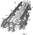
- Fig. 1 shows a perspective view of an embodiment of a bonding device 10 according to the invention, in which an embodiment of a rotor blade 5 according to the invention is added.
- the rotor blade 5 is constructed from three different rotor blade parts 1, 2 and 3.
- the first rotor blade part 1 is designed as a nose shell 1, the second rotor blade part 2 as Mitteilteilsegment 2 and the third rotor blade part 3 as a trailing edge segment 3.
- the adhesive areas 21 between the nose shell 1 and the middle segment 2 are oriented substantially in the longitudinal direction and are both on the Suction as formed on the pressure side of the rotor blade.
- the adhesive areas 22 between the trailing edge segment 1 and the middle segment 2 are oriented substantially in the longitudinal direction and formed both on the suction and on the pressure side of the rotor blade.
- Both the nose shell 1, as well as the trailing edge segment 3 are each connected to the flange 4 by a belt 6, which is anchored in each case in the interior of the nose shell 1, and the trailing edge segment 3.
- the flange 4 is also arranged in a fourth receiving area 14. This arrangement of the flange is done by screwing some of the bolts 4 provided on the flange. By screwing the flange 4 is spatially fixed, so that a movement of the flange 4 would be possible only unintentionally and after spending large mechanical forces.
- an opening 25 which can still ensure access to the interior of the rotor blade 5.
- the opening is required to further process the straps or the webs in the interior of the rotor blade 5.
- the opening 25 is closed with a not further shown component, wherein the outer skin of the rotor blade 5 is attached to the flange 4 on all sides.
- the closing of the opening 25 takes place by bonding the component to the boundaries, which are designed as adhesive areas, with an adhesive to the middle segment 2 and the nose shell 1. Curing by Heat on the adhesive can also be done with a device not shown.
- a first prefabricated rotor blade part 1 (nose cup) is first inserted into the first receptacle 11 of the gluing device 10 and fastened thereto.
- the attachment takes place by means of suitably mounted suction nozzle, which allow a holder by means of negative pressure.
- a third prefabricated rotor blade part 1 (nose cup) is inserted and fastened.
- the attachment is again by mounting by means of negative pressure.
- the recordings 11 and 13 have inserts which correspond to the geometric peripheral shape of the rotor blade parts 1 and 3 and thus support the accurately fitting insertion.
- the inserts are each attached to a first support structure 15 and a third support structure 17.
- the support structures 15 and 17 are each supported on a set of rails 31 against the bottom floor and can be moved towards each other or away from each other.
- a further second holding structure 16 is arranged, on which also a not shown or visible second receiving area 12 is provided.
- the second receiving region 12 serves to receive the second prefabricated rotor blade part 2, which is designed as a middle segment 2, which is arranged in the rotor blade 5 between the nose shell 1 and the trailing edge segment 3.
- the first holding structure 15 with the first rotor blade part 1 (nose cup) accommodated in the first receiving area 11 provided therein and the third holding structure 17 with the third rotor blade part 3 accommodated in the third receiving area 13 provided therein (Trailing edge segment) relative to each other moves, ie both moved to the recorded in the second receiving portion 12 second rotor blade part 2.
- the second receiving area 12 and the second rotor blade part 2 accommodated therein thus remain stationary in space, like the flange 4.
- the movement takes place until the adhesive areas 21 of the nose shell 1 and the adhesive areas 21 of the middle segment 2 are sufficiently in contact with each other. Direct and direct contact can be prevented by the adhesive applied to the gluing areas 21. In any case, however, the approach of both components is sufficiently close to be able to bring about a bonding by means of the adhesive can.
- the movement is made so that the bonding areas 22 of the trailing edge segment 3 and the middle part segment 2 are sufficiently in contact with each other. Direct and direct contact can in turn be prevented by the adhesive applied to the gluing areas 22. In any case, however, the approach of both components is sufficiently close to be able to cause a bond.
- the movement of the first holding structure 15 and the third holding structure 17 can take place at the same time or in a time offset.
- thermal energy is supplied in a localized manner along the two bonding areas 21 and 22 by means of the tempering devices 40, which are respectively provided in the first receiving area 11 and the third receiving area 13.
- the tempering devices 40 are arranged and geometrically designed such that essentially only the adhesive areas 21 and 22 are supplied with thermal energy. This leads to a targeted hardening of the not yet cured adhesive in the adhesive areas 21 and 22 and thus connects the first rotor blade part 1 (nose shell), the second rotor blade part 2 (middle segment) and the third rotor blade part 3 (trailing edge segment) firmly together.
- connection with the flange 4 is also carried out with the first rotor blade part 1 (nose cup), the second rotor blade part 2 (middle part segment) and the third rotor blade part 3 (trailing edge segment), wherein the curing of the adhesive in the non further provided with reference numerals adhesive areas in the present case with a tempering device not shown.
- connection of the belt ends 6 on the side of the first rotor blade part 1 and the third rotor blade part 3 is carried out according to the implementation by means of laterally arranged pressure units 50, which can also be moved in the direction of the flange 4 on rails. After sufficient approach preformed surfaces press against the strap ends 6, which are glued to the flange and thus cause a pressing of the strap ends 6 against predetermined areas on the flange 4. Curing can take place by heat at these areas.
- an annealing device may in turn be provided on or in the pressing regions.
- the movement of both the pressing units 50 and the first holding structure 15 and the third holding structure 17 can be controlled away and individually controlled.
- Fig. 2 shows a perspective side view of the embodiment of a gluing device 10 according to the invention Fig. 1 in which no rotor blade is received.
- the fourth receiving area 14 is shown, which is provided for holding the flange 4.
- the flange 4 is held in this case by means of a few bolts of the bolt rim, which are received by pin receivers 18.
- the bolt receivers 18 are designed as bushings 18, through which the bolts are guided and screwed on the opposite side.
- the second receiving area 12 which itself is mounted on the second holding structure 16 (the second receiving area 12 and the second holding structure 16, which are both arranged in the image plane behind the fourth receiving area 14, are shown in perspective).
- Fig. 3 shows a perspective view of the embodiment of a gluing device 10 according to the invention according to the previous figures, in which no rotor blade 5 is received. It is clearly recognizable in the Representation of the first support structure 15, which has a first receiving portion 11 for receiving a first rotor blade part 1 not shown (nose cup). Furthermore, the third holding structure 17 can be seen, which has a third receiving area 13 for receiving a third rotor blade part 3 (rear edge segment), not shown. Both holding structures 15 and 17 are each arranged on one side of the second receiving area 12, which is mounted on a second holding structure 16.
- a pair of mutually parallel rails 31, which are provided for a respective gluing apparatus 30 (see also FIG Fig. 5 ).
- Such gluing apparatuses can be displaced along these rails 31, so that all gluing areas 21 and 22 of the rotor blade parts 1, 2 and 3 (not shown further) can be supplied and provided with adhesive.
- the rails 31 extend substantially parallel to the longitudinal extension of the second receiving region 12.
- FIG. 3 shows Fig. 3 on the side of the first support structure 15 a set of three pairs of parallel rails 31. These serve the first support structure 15 for movement in the direction of the second receiving portion 12 to.
- a set of four pairs of parallel rails 31 is arranged on the side of the third support structure 17. These also serve the third holding structure 17 for movement in the direction of the second receiving area 12.
- These pairs of rails are arranged in their course substantially perpendicular to the rails 31, which are provided for the gluing apparatus.
- Fig. 4 shows a perspective view of the second receiving portion 12 for receiving a middle segment of an embodiment of a rotor blade according to the invention 5 (not shown) corresponding to the embodiment of the gluing device 10 shown in the preceding figures.
- the second receiving portion 12 is in this case divided into two and is supported by a second support structure 16.
- the fourth receiving area 14 for holding the flange 4 is provided in an extension of the longitudinal extension direction of the second receiving area 12.
- the second receiving area 12 is interrupted approximately in the middle of its longitudinal extent and has a recess. This recess may be advantageous for the adjustment if it has approximately alignment aids, which are not shown here.
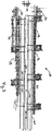
- Fig. 5 shows a perspective view of a gluing apparatus 30 of a not further shown embodiment of the gluing device 10 shown in the preceding figures.
- the gluing device 10 is adapted to accommodate several people (in the present case three persons), which can work on different levels.
- the gluing apparatus 30 has two passenger platforms 35, which can be moved in height (according to the orientation shown).
- the persons may be equipped with hoses (not shown here) which are suitable for application and metering of adhesive (for example commercial epoxy adhesives).
- the hoses can also have suitable outlet nozzles from which the adhesive is dispensed.
- the hoses open on the other side of the hose in an output unit 36, which is provided with a suitable control.
- the dispenser unit 36 cooperates with a pump (not shown) which distributes the ready adhesive to the tubing. From the output unit 36, the tubes each go upwards (according to the present orientation) and are held on a hose holder 38 for strain relief. The adhesive is removed from the reservoir 37.
- the gluing apparatus 30 is supported by rail rollers 39 against rails 31, not shown further, and can be moved approximately autonomously on them by a suitable drive device (not shown).
Landscapes
- Engineering & Computer Science (AREA)
- Mechanical Engineering (AREA)
- Life Sciences & Earth Sciences (AREA)
- Sustainable Development (AREA)
- Sustainable Energy (AREA)
- Chemical & Material Sciences (AREA)
- Combustion & Propulsion (AREA)
- General Engineering & Computer Science (AREA)
- Wind Motors (AREA)
- Lining Or Joining Of Plastics Or The Like (AREA)
Claims (12)
- Dispositif de collage (10) pour la construction de pales de rotor segmentées (5) comprenant au moins trois parties de pale de rotor préfabriquées, à savoir une coque de bec (1), un segment de partie intermédiaire (2) et un segment de bord arrière (3), présentant:
une première zone de réception (11) pour la réception de la coque de bec préfabriquée (1), une deuxième zone de réception (12) pour la réception du segment de partie intermédiaire préfabriqué (2) et une troisième zone de réception (13) pour la réception du segment de bord arrière préfabriqué (3), dans lequel la première zone de réception (11), la deuxième zone de réception (12) et la troisième zone de réception (13) peuvent être déplacées l'une par rapport à l'autre, de telle manière qu'après la mise en place des trois parties de pale de rotor préfabriquées (1, 2, 3) dans les zones de réception adéquates (11, 12, 13) dans une position ouverte du dispositif de collage (10), ces parties de pale de rotor (1, 2, 3) puissent être mises en contact direct ou indirect l'une avec l'autre par des zones de collage prédéterminées (21, 22) et puissent ainsi être amenées dans une position de collage, dans lequel il est prévu entre une première structure de maintien (15) pour la première zone de réception (11) et une troisième structure de maintien (17) pour la troisième zone de réception (13) une deuxième structure de maintien (16) pour la deuxième zone de maintien (12), caractérisé en ce que la première structure de maintien (11) avec la première zone de réception (11) et la coque de bec (1) ainsi que la troisième structure de maintien (17) avec la troisième zone de réception (13) et le segment de bord arrière (3) peuvent être déplacées vers le segment de partie intermédiaire (2) placé dans la deuxième zone de réception (12) tandis que la deuxième zone de réception (12) avec le segment de partie intermédiaire (2) reste immobile dans l'espace. - Dispositif de collage selon la revendication 1, caractérisé en ce que le dispositif de collage (10) présente au moins une autre quatrième zone de réception (14), qui est configurée pour recevoir ou supporter une bride (4), qui peut être collée en particulier à au moins une des trois parties de pale de rotor préfabriquées (1, 2, 3) au moyen d'une zone de collage prédéterminée (23, 24).
- Dispositif de collage selon l'une quelconque des revendications précédentes, caractérisé en ce qu'au moins une des quatre zones de réception (11, 12, 13, 14) peut être inclinée par rapport à une des autres zones de réception (11, 12, 13, 14) lors de l'amenée des parties de pale de rotor préfabriquées disposées dans les zones de réception dans la position de collage.
- Dispositif de collage selon l'une quelconque des revendications précédentes, caractérisé en ce que la première zone de réception (11), la deuxième zone de réception (12) et la troisième zone de réception (13) exécutent l'une par rapport à l'autre un mouvement vertical par rapport à l'allure du champ d'accélération terrestre lors de l'amenée des parties de pale de rotor (1, 2, 3) préfabriquées, disposées dans les trois zones de réception (11, 12, 13), dans la position de collage.
- Dispositif de collage selon l'une quelconque des revendications précédentes, caractérisé en ce qu'au moins une des trois zones de réception (11, 12, 13) est réalisée sous forme pivotante, en particulier sous forme pivotante sur au moins 90°.
- Dispositif de collage selon l'une quelconque des revendications précédentes, caractérisé en ce qu'au moins une des zones de réception (11, 12, 13, 14) peut être adaptée à une forme géométrique de la partie de pale de rotor (1, 2, 3) ou de la bride préfabriquée prévue de manière adéquate pour la réception.
- Dispositif de collage selon l'une quelconque des revendications précédentes, caractérisé en ce qu'au moins une de la première, de la deuxième ou de la troisième zone de réception (11, 12, 13) du dispositif de collage (10) présente une extension longitudinale, qui est orientée essentiellement parallèlement à l'extension longitudinale de la pale de rotor à construire (5).
- Dispositif de collage selon l'une quelconque des revendications précédentes, caractérisé en ce que le dispositif de collage présente un appareillage de collage (30), qui est déplaçable au moins en partie le long des zones de collage prédéterminées (21, 22, 23, 24).
- Dispositif de collage selon l'une quelconque des revendications précédentes, caractérisé en ce que le dispositif de collage (10) présente au moins un dispositif d'égalisation de la température (40), qui est configuré de telle manière qu'il envoie de la chaleur à des zones de collage prédéterminées localement limitées (21, 22, 23, 24) d'au moins une des parties de pale de rotor préfabriquées (1, 2, 3) ou de la bride (4).
- Dispositif de collage selon l'une quelconque des revendications précédentes 2 à 9, caractérisé en ce que le dispositif de collage (10) présente au moins une unité de pression (50), qui est configurée de telle manière qu'elle puisse presser une ou plusieurs extrémité(s) de ceinture (6) des parties de pale de rotor préfabriquées (1, 2, 3) pour le collage à la bride (4).
- Dispositif de collage selon l'une quelconque des revendications précédentes, caractérisé en ce que le dispositif de collage (10) présente au moins une unité d'aspiration (60), qui permet de soutenir au moins une des parties de pale de rotor (1, 2, 3) au moyen d'une dépression dans la zone de réception respective.
- Procédé de collage d'au moins trois parties de pale de rotor préfabriquées, à savoir une coque de bec (1), un segment de partie intermédiaire (2) et un segment de bord arrière (3), pour la construction d'une pale de rotor segmentée, dans lequel on colle les parties de pale de rotor (1, 2, 3) à l'aide d'un dispositif de collage (10), de telle manière que les trois parties de pale de rotor soient toutes reçues dans le dispositif de collage (10) et soient amenées par des zones de collage prédéterminées avec une autre partie de pale de rotor (1, 2, 3) en contact direct ou indirect pour le collage dans une position de collage, caractérisé en ce que l'on déplace une première structure de maintien (15) avec une première zone de réception (11) et la coque de bec (1) ainsi qu'une troisième structure de maintien (17) avec une troisième zone de réception (13) et le segment de bord arrière (3) vers le segment de partie intermédiaire (2), tandis qu'une deuxième zone de réception (12) avec le segment de partie intermédiaire (2) reste immobile dans l'espace.
Applications Claiming Priority (2)
| Application Number | Priority Date | Filing Date | Title |
|---|---|---|---|
| DE102011078804A DE102011078804A1 (de) | 2011-07-07 | 2011-07-07 | Verklebeeinrichtung zum Bau von segmentierten Rotorblättern |
| PCT/EP2012/060667 WO2013004445A1 (fr) | 2011-07-07 | 2012-06-06 | Dispositif de collage pour la construction de pales de rotor segmentées |
Publications (2)
| Publication Number | Publication Date |
|---|---|
| EP2729295A1 EP2729295A1 (fr) | 2014-05-14 |
| EP2729295B1 true EP2729295B1 (fr) | 2019-08-07 |
Family
ID=46229489
Family Applications (1)
| Application Number | Title | Priority Date | Filing Date |
|---|---|---|---|
| EP12726426.5A Active EP2729295B1 (fr) | 2011-07-07 | 2012-06-06 | Dispositif de collage pour la construction de pales de rotor segmentées |
Country Status (7)
| Country | Link |
|---|---|
| US (1) | US9689371B2 (fr) |
| EP (1) | EP2729295B1 (fr) |
| JP (1) | JP5908074B2 (fr) |
| CN (1) | CN103648752B (fr) |
| AU (1) | AU2012280585B2 (fr) |
| DE (1) | DE102011078804A1 (fr) |
| WO (1) | WO2013004445A1 (fr) |
Families Citing this family (7)
| Publication number | Priority date | Publication date | Assignee | Title |
|---|---|---|---|---|
| US10118352B2 (en) * | 2013-05-31 | 2018-11-06 | LM WP Patent Holdings A/S | System and method for assisting in the manufacture of a wind turbine blade shell |
| CN103331236B (zh) * | 2013-07-10 | 2015-07-15 | 洛阳双瑞风电叶片有限公司 | 一种风力发电机叶片后缘打胶工装及制备方法 |
| DE102014206751A1 (de) * | 2014-04-08 | 2015-10-08 | Bayerische Motoren Werke Aktiengesellschaft | Verfahren und Fertigungssystem zum Kaschieren von Interieurkomponenten von Fahrzeugen |
| ES2887979T3 (es) | 2017-01-12 | 2021-12-29 | Vestas Wind Sys As | Método y aparato para ensamblar una pala de aerogenerador que tiene una membrana interna |
| US11181094B2 (en) | 2018-06-12 | 2021-11-23 | Tpi Composites, Inc. | Wind blade component bonding fixture |
| DE102018128863A1 (de) * | 2018-11-16 | 2020-05-20 | HELLA GmbH & Co. KGaA | Verfahren zum Verkleben von zwei lagegenau zueinander angeordneten Bauteilen |
| CN117507380A (zh) * | 2023-12-07 | 2024-02-06 | 新创碳谷集团有限公司 | 一种模块化叶片主梁粘接装置及方法 |
Family Cites Families (6)
| Publication number | Priority date | Publication date | Assignee | Title |
|---|---|---|---|---|
| DE102004021389A1 (de) | 2004-04-30 | 2005-11-24 | Daimlerchrysler Ag | Verfahren und Vorrichtung zum Verbinden von mindestens zwei Werkstücken |
| ES2342638B1 (es) | 2007-02-28 | 2011-05-13 | GAMESA INNOVATION & TECHNOLOGY, S.L. | Una pala de aerogenerador multi-panel. |
| CN102016297B (zh) * | 2008-03-05 | 2013-05-01 | 维斯塔斯风力系统有限公司 | 组装工具以及制造风轮机叶片的方法 |
| GB0807515D0 (en) * | 2008-04-24 | 2008-06-04 | Blade Dynamics Ltd | A wind turbine blade |
| DE102008038620A1 (de) * | 2008-06-27 | 2009-12-31 | Powerblades Gmbh | Verfahren und Fertigungsform zur Fertigung eines Rotorblattes für eine Windenergieanlage |
| DE102009033164A1 (de) * | 2009-07-13 | 2011-01-27 | Repower Systems Ag | Rotorblatt einer Windenergieanlage sowie Verfahren zum Fertigen eines Rotorblattes einer Windenergieanlage |
-
2011
- 2011-07-07 DE DE102011078804A patent/DE102011078804A1/de not_active Ceased
-
2012
- 2012-06-06 WO PCT/EP2012/060667 patent/WO2013004445A1/fr active Application Filing
- 2012-06-06 JP JP2014517558A patent/JP5908074B2/ja active Active
- 2012-06-06 EP EP12726426.5A patent/EP2729295B1/fr active Active
- 2012-06-06 AU AU2012280585A patent/AU2012280585B2/en not_active Ceased
- 2012-06-06 CN CN201280033836.0A patent/CN103648752B/zh not_active Expired - Fee Related
-
2014
- 2014-01-07 US US14/148,934 patent/US9689371B2/en not_active Expired - Fee Related
Non-Patent Citations (1)
| Title |
|---|
| None * |
Also Published As
| Publication number | Publication date |
|---|---|
| US20140119935A1 (en) | 2014-05-01 |
| JP2014520994A (ja) | 2014-08-25 |
| AU2012280585B2 (en) | 2015-03-12 |
| EP2729295A1 (fr) | 2014-05-14 |
| JP5908074B2 (ja) | 2016-04-26 |
| DE102011078804A1 (de) | 2013-01-10 |
| AU2012280585A1 (en) | 2013-05-02 |
| WO2013004445A1 (fr) | 2013-01-10 |
| CN103648752A (zh) | 2014-03-19 |
| US9689371B2 (en) | 2017-06-27 |
| CN103648752B (zh) | 2016-12-21 |
Similar Documents
| Publication | Publication Date | Title |
|---|---|---|
| EP2729295B1 (fr) | Dispositif de collage pour la construction de pales de rotor segmentées | |
| AT510694B1 (de) | Modul zum halten von mindestens einer hülse | |
| EP2454472B1 (fr) | Pale de rotor d'éolienne et procédé de fabrication d'une pale de rotor d'éolienne | |
| EP2909015B1 (fr) | Système et procédé de fabrication d'une semelle de longeron de pale de rotor | |
| DE2738895C2 (fr) | ||
| EP2512765B1 (fr) | Dispositif de fabrication d'un fuselage constitué d'un matériau renforcé par des fibres pour un aéronef | |
| DE19956394B4 (de) | Verfahren zur Herstellung eines Profiles aus einem Hybridwerkstoff | |
| DE3113791C2 (fr) | ||
| DE102005026010A1 (de) | Verfahren zur Herstellung einer verstärkten Schale zur Bildung von Teilkomponenten für Luftfahrzeuge sowie Schale zur Bildung von Teilkomponenten für Luftfahrzeuge | |
| EP2477800B1 (fr) | Procédé pour raidir des éléments en composite renforcé de fibres, et dispositif de fabrication d'un élément en composite renforcé de fibres raidi | |
| DE102016210086A1 (de) | Verfahren zum Herstellen eines Strukturbauteils für ein Luft- oder Raumfahrzeug, sowie Anordnung | |
| DE102008021788A1 (de) | Verfahren zum Reparieren einer Flugzeugkomponente | |
| EP2454474B1 (fr) | Pale rotorique d'une éolienne, procédé de production d'une pale rotorique et paire de courroies pour une pale rotorique | |
| EP3444107A1 (fr) | Procédé de fabrication d'un composant sandwich, noyau pour un composant sandwich ainsi qu'un composant sandwich | |
| EP2712724A1 (fr) | Eléments de renforcement intégraux | |
| EP3877159B1 (fr) | Dispositif et procédé pour réaliser une pale de rotor destinée à une éolienne et éolienne correspondante | |
| WO2015049088A1 (fr) | Composant de véhicule en matière synthétique renforcée par des fibres et procédé de réparation de composants en matière synthétique renforcée par des fibres qui ont été endommagés | |
| EP2388194A2 (fr) | Positionnement de longeron | |
| DE102012223810A1 (de) | Variable Formvorrichtung zur Herstellung einer Halbschale für ein Rotorblatt für eine Windenergieanlage | |
| DE102010017022A1 (de) | Verfahren zum Herstellen eines Hohlprofils | |
| DE102012003378A1 (de) | Verfahren zum Herstellen einer Blindverklebung zwischen zwei Bauteilen eines Windenergieanlagenrotorblatts | |
| DE102009057009B4 (de) | Vorrichtung und Verfahren zur Herstellung eines schalenförmigen Verbundbauteils | |
| EP3578349B1 (fr) | Procédé et dispositif de fabrication d'une pâle de rotor pour une éolienne | |
| EP3360671B1 (fr) | Pré-moule rotatif pour une préforme | |
| EP2648887B1 (fr) | Procédé et dispositif pour la production d'un caisson de longeron pour une pale de rotor, caisson de longeron correspondant |
Legal Events
| Date | Code | Title | Description |
|---|---|---|---|
| PUAI | Public reference made under article 153(3) epc to a published international application that has entered the european phase |
Free format text: ORIGINAL CODE: 0009012 |
|
| 17P | Request for examination filed |
Effective date: 20140207 |
|
| AK | Designated contracting states |
Kind code of ref document: A1 Designated state(s): AL AT BE BG CH CY CZ DE DK EE ES FI FR GB GR HR HU IE IS IT LI LT LU LV MC MK MT NL NO PL PT RO RS SE SI SK SM TR |
|
| RAP1 | Party data changed (applicant data changed or rights of an application transferred) |
Owner name: CARBON ROTEC GMBH & CO. KG |
|
| RIN1 | Information on inventor provided before grant (corrected) |
Inventor name: DAENEKAS, KAI Inventor name: WEIGEL, LARS Inventor name: DREWES, MARCUS |
|
| DAX | Request for extension of the european patent (deleted) | ||
| 17Q | First examination report despatched |
Effective date: 20161012 |
|
| STAA | Information on the status of an ep patent application or granted ep patent |
Free format text: STATUS: EXAMINATION IS IN PROGRESS |
|
| 19U | Interruption of proceedings before grant |
Effective date: 20180101 |
|
| 19W | Proceedings resumed before grant after interruption of proceedings |
Effective date: 20181001 |
|
| GRAP | Despatch of communication of intention to grant a patent |
Free format text: ORIGINAL CODE: EPIDOSNIGR1 |
|
| RIC1 | Information provided on ipc code assigned before grant |
Ipc: B29L 31/08 20060101ALN20181203BHEP Ipc: B29C 65/48 20060101AFI20181203BHEP Ipc: B29C 65/02 20060101ALN20181203BHEP Ipc: F03D 13/10 20160101ALI20181203BHEP Ipc: B29C 65/78 20060101ALI20181203BHEP Ipc: F03D 1/06 20060101ALI20181203BHEP Ipc: B29C 65/52 20060101ALN20181203BHEP |
|
| STAA | Information on the status of an ep patent application or granted ep patent |
Free format text: STATUS: GRANT OF PATENT IS INTENDED |
|
| RIC1 | Information provided on ipc code assigned before grant |
Ipc: F03D 1/06 20060101ALI20181210BHEP Ipc: F03D 13/10 20160101ALI20181210BHEP Ipc: B29C 65/78 20060101ALI20181210BHEP Ipc: B29C 65/02 20060101ALN20181210BHEP Ipc: B29L 31/08 20060101ALN20181210BHEP Ipc: B29C 65/48 20060101AFI20181210BHEP Ipc: B29C 65/52 20060101ALN20181210BHEP |
|
| RIC1 | Information provided on ipc code assigned before grant |
Ipc: F03D 1/06 20060101ALI20181219BHEP Ipc: B29C 65/52 20060101ALN20181219BHEP Ipc: B29C 65/48 20060101AFI20181219BHEP Ipc: B29L 31/08 20060101ALN20181219BHEP Ipc: F03D 13/10 20160101ALI20181219BHEP Ipc: B29C 65/02 20060101ALN20181219BHEP Ipc: B29C 65/78 20060101ALI20181219BHEP |
|
| INTG | Intention to grant announced |
Effective date: 20190110 |
|
| RIC1 | Information provided on ipc code assigned before grant |
Ipc: B29C 65/78 20060101ALI20181219BHEP Ipc: F03D 13/10 20160101ALI20181219BHEP Ipc: B29C 65/48 20060101AFI20181219BHEP Ipc: F03D 1/06 20060101ALI20181219BHEP Ipc: B29C 65/02 20060101ALN20181219BHEP Ipc: B29L 31/08 20060101ALN20181219BHEP Ipc: B29C 65/52 20060101ALN20181219BHEP |
|
| GRAS | Grant fee paid |
Free format text: ORIGINAL CODE: EPIDOSNIGR3 |
|
| GRAA | (expected) grant |
Free format text: ORIGINAL CODE: 0009210 |
|
| STAA | Information on the status of an ep patent application or granted ep patent |
Free format text: STATUS: THE PATENT HAS BEEN GRANTED |
|
| AK | Designated contracting states |
Kind code of ref document: B1 Designated state(s): AL AT BE BG CH CY CZ DE DK EE ES FI FR GB GR HR HU IE IS IT LI LT LU LV MC MK MT NL NO PL PT RO RS SE SI SK SM TR |
|
| REG | Reference to a national code |
Ref country code: GB Ref legal event code: FG4D Free format text: NOT ENGLISH |
|
| REG | Reference to a national code |
Ref country code: CH Ref legal event code: EP Ref country code: AT Ref legal event code: REF Ref document number: 1163164 Country of ref document: AT Kind code of ref document: T Effective date: 20190815 |
|
| REG | Reference to a national code |
Ref country code: DE Ref legal event code: R096 Ref document number: 502012015127 Country of ref document: DE |
|
| REG | Reference to a national code |
Ref country code: IE Ref legal event code: FG4D Free format text: LANGUAGE OF EP DOCUMENT: GERMAN |
|
| REG | Reference to a national code |
Ref country code: NL Ref legal event code: MP Effective date: 20190807 |
|
| REG | Reference to a national code |
Ref country code: LT Ref legal event code: MG4D |
|
| PG25 | Lapsed in a contracting state [announced via postgrant information from national office to epo] |
Ref country code: PT Free format text: LAPSE BECAUSE OF FAILURE TO SUBMIT A TRANSLATION OF THE DESCRIPTION OR TO PAY THE FEE WITHIN THE PRESCRIBED TIME-LIMIT Effective date: 20191209 Ref country code: SE Free format text: LAPSE BECAUSE OF FAILURE TO SUBMIT A TRANSLATION OF THE DESCRIPTION OR TO PAY THE FEE WITHIN THE PRESCRIBED TIME-LIMIT Effective date: 20190807 Ref country code: BG Free format text: LAPSE BECAUSE OF FAILURE TO SUBMIT A TRANSLATION OF THE DESCRIPTION OR TO PAY THE FEE WITHIN THE PRESCRIBED TIME-LIMIT Effective date: 20191107 Ref country code: NO Free format text: LAPSE BECAUSE OF FAILURE TO SUBMIT A TRANSLATION OF THE DESCRIPTION OR TO PAY THE FEE WITHIN THE PRESCRIBED TIME-LIMIT Effective date: 20191107 Ref country code: FI Free format text: LAPSE BECAUSE OF FAILURE TO SUBMIT A TRANSLATION OF THE DESCRIPTION OR TO PAY THE FEE WITHIN THE PRESCRIBED TIME-LIMIT Effective date: 20190807 Ref country code: NL Free format text: LAPSE BECAUSE OF FAILURE TO SUBMIT A TRANSLATION OF THE DESCRIPTION OR TO PAY THE FEE WITHIN THE PRESCRIBED TIME-LIMIT Effective date: 20190807 Ref country code: LT Free format text: LAPSE BECAUSE OF FAILURE TO SUBMIT A TRANSLATION OF THE DESCRIPTION OR TO PAY THE FEE WITHIN THE PRESCRIBED TIME-LIMIT Effective date: 20190807 Ref country code: HR Free format text: LAPSE BECAUSE OF FAILURE TO SUBMIT A TRANSLATION OF THE DESCRIPTION OR TO PAY THE FEE WITHIN THE PRESCRIBED TIME-LIMIT Effective date: 20190807 |
|
| PG25 | Lapsed in a contracting state [announced via postgrant information from national office to epo] |
Ref country code: AL Free format text: LAPSE BECAUSE OF FAILURE TO SUBMIT A TRANSLATION OF THE DESCRIPTION OR TO PAY THE FEE WITHIN THE PRESCRIBED TIME-LIMIT Effective date: 20190807 Ref country code: LV Free format text: LAPSE BECAUSE OF FAILURE TO SUBMIT A TRANSLATION OF THE DESCRIPTION OR TO PAY THE FEE WITHIN THE PRESCRIBED TIME-LIMIT Effective date: 20190807 Ref country code: GR Free format text: LAPSE BECAUSE OF FAILURE TO SUBMIT A TRANSLATION OF THE DESCRIPTION OR TO PAY THE FEE WITHIN THE PRESCRIBED TIME-LIMIT Effective date: 20191108 Ref country code: RS Free format text: LAPSE BECAUSE OF FAILURE TO SUBMIT A TRANSLATION OF THE DESCRIPTION OR TO PAY THE FEE WITHIN THE PRESCRIBED TIME-LIMIT Effective date: 20190807 Ref country code: IS Free format text: LAPSE BECAUSE OF FAILURE TO SUBMIT A TRANSLATION OF THE DESCRIPTION OR TO PAY THE FEE WITHIN THE PRESCRIBED TIME-LIMIT Effective date: 20191207 Ref country code: ES Free format text: LAPSE BECAUSE OF FAILURE TO SUBMIT A TRANSLATION OF THE DESCRIPTION OR TO PAY THE FEE WITHIN THE PRESCRIBED TIME-LIMIT Effective date: 20190807 |
|
| PG25 | Lapsed in a contracting state [announced via postgrant information from national office to epo] |
Ref country code: TR Free format text: LAPSE BECAUSE OF FAILURE TO SUBMIT A TRANSLATION OF THE DESCRIPTION OR TO PAY THE FEE WITHIN THE PRESCRIBED TIME-LIMIT Effective date: 20190807 |
|
| PG25 | Lapsed in a contracting state [announced via postgrant information from national office to epo] |
Ref country code: IT Free format text: LAPSE BECAUSE OF FAILURE TO SUBMIT A TRANSLATION OF THE DESCRIPTION OR TO PAY THE FEE WITHIN THE PRESCRIBED TIME-LIMIT Effective date: 20190807 Ref country code: PL Free format text: LAPSE BECAUSE OF FAILURE TO SUBMIT A TRANSLATION OF THE DESCRIPTION OR TO PAY THE FEE WITHIN THE PRESCRIBED TIME-LIMIT Effective date: 20190807 Ref country code: EE Free format text: LAPSE BECAUSE OF FAILURE TO SUBMIT A TRANSLATION OF THE DESCRIPTION OR TO PAY THE FEE WITHIN THE PRESCRIBED TIME-LIMIT Effective date: 20190807 Ref country code: DK Free format text: LAPSE BECAUSE OF FAILURE TO SUBMIT A TRANSLATION OF THE DESCRIPTION OR TO PAY THE FEE WITHIN THE PRESCRIBED TIME-LIMIT Effective date: 20190807 Ref country code: RO Free format text: LAPSE BECAUSE OF FAILURE TO SUBMIT A TRANSLATION OF THE DESCRIPTION OR TO PAY THE FEE WITHIN THE PRESCRIBED TIME-LIMIT Effective date: 20190807 |
|
| PG25 | Lapsed in a contracting state [announced via postgrant information from national office to epo] |
Ref country code: CZ Free format text: LAPSE BECAUSE OF FAILURE TO SUBMIT A TRANSLATION OF THE DESCRIPTION OR TO PAY THE FEE WITHIN THE PRESCRIBED TIME-LIMIT Effective date: 20190807 Ref country code: IS Free format text: LAPSE BECAUSE OF FAILURE TO SUBMIT A TRANSLATION OF THE DESCRIPTION OR TO PAY THE FEE WITHIN THE PRESCRIBED TIME-LIMIT Effective date: 20200224 Ref country code: SM Free format text: LAPSE BECAUSE OF FAILURE TO SUBMIT A TRANSLATION OF THE DESCRIPTION OR TO PAY THE FEE WITHIN THE PRESCRIBED TIME-LIMIT Effective date: 20190807 Ref country code: SK Free format text: LAPSE BECAUSE OF FAILURE TO SUBMIT A TRANSLATION OF THE DESCRIPTION OR TO PAY THE FEE WITHIN THE PRESCRIBED TIME-LIMIT Effective date: 20190807 |
|
| REG | Reference to a national code |
Ref country code: DE Ref legal event code: R097 Ref document number: 502012015127 Country of ref document: DE |
|
| PLBE | No opposition filed within time limit |
Free format text: ORIGINAL CODE: 0009261 |
|
| STAA | Information on the status of an ep patent application or granted ep patent |
Free format text: STATUS: NO OPPOSITION FILED WITHIN TIME LIMIT |
|
| PG2D | Information on lapse in contracting state deleted |
Ref country code: IS |
|
| 26N | No opposition filed |
Effective date: 20200603 |
|
| PG25 | Lapsed in a contracting state [announced via postgrant information from national office to epo] |
Ref country code: SI Free format text: LAPSE BECAUSE OF FAILURE TO SUBMIT A TRANSLATION OF THE DESCRIPTION OR TO PAY THE FEE WITHIN THE PRESCRIBED TIME-LIMIT Effective date: 20190807 |
|
| REG | Reference to a national code |
Ref country code: DE Ref legal event code: R119 Ref document number: 502012015127 Country of ref document: DE |
|
| PG25 | Lapsed in a contracting state [announced via postgrant information from national office to epo] |
Ref country code: MC Free format text: LAPSE BECAUSE OF FAILURE TO SUBMIT A TRANSLATION OF THE DESCRIPTION OR TO PAY THE FEE WITHIN THE PRESCRIBED TIME-LIMIT Effective date: 20190807 |
|
| REG | Reference to a national code |
Ref country code: CH Ref legal event code: PL |
|
| GBPC | Gb: european patent ceased through non-payment of renewal fee |
Effective date: 20200606 |
|
| PG25 | Lapsed in a contracting state [announced via postgrant information from national office to epo] |
Ref country code: LU Free format text: LAPSE BECAUSE OF NON-PAYMENT OF DUE FEES Effective date: 20200606 |
|
| REG | Reference to a national code |
Ref country code: BE Ref legal event code: MM Effective date: 20200630 |
|
| PG25 | Lapsed in a contracting state [announced via postgrant information from national office to epo] |
Ref country code: IE Free format text: LAPSE BECAUSE OF NON-PAYMENT OF DUE FEES Effective date: 20200606 Ref country code: LI Free format text: LAPSE BECAUSE OF NON-PAYMENT OF DUE FEES Effective date: 20200630 Ref country code: CH Free format text: LAPSE BECAUSE OF NON-PAYMENT OF DUE FEES Effective date: 20200630 Ref country code: GB Free format text: LAPSE BECAUSE OF NON-PAYMENT OF DUE FEES Effective date: 20200606 Ref country code: FR Free format text: LAPSE BECAUSE OF NON-PAYMENT OF DUE FEES Effective date: 20200630 |
|
| PG25 | Lapsed in a contracting state [announced via postgrant information from national office to epo] |
Ref country code: BE Free format text: LAPSE BECAUSE OF NON-PAYMENT OF DUE FEES Effective date: 20200630 Ref country code: DE Free format text: LAPSE BECAUSE OF NON-PAYMENT OF DUE FEES Effective date: 20210101 |
|
| REG | Reference to a national code |
Ref country code: AT Ref legal event code: MM01 Ref document number: 1163164 Country of ref document: AT Kind code of ref document: T Effective date: 20200606 |
|
| PG25 | Lapsed in a contracting state [announced via postgrant information from national office to epo] |
Ref country code: AT Free format text: LAPSE BECAUSE OF NON-PAYMENT OF DUE FEES Effective date: 20200606 |
|
| PG25 | Lapsed in a contracting state [announced via postgrant information from national office to epo] |
Ref country code: MT Free format text: LAPSE BECAUSE OF FAILURE TO SUBMIT A TRANSLATION OF THE DESCRIPTION OR TO PAY THE FEE WITHIN THE PRESCRIBED TIME-LIMIT Effective date: 20190807 Ref country code: CY Free format text: LAPSE BECAUSE OF FAILURE TO SUBMIT A TRANSLATION OF THE DESCRIPTION OR TO PAY THE FEE WITHIN THE PRESCRIBED TIME-LIMIT Effective date: 20190807 |
|
| PG25 | Lapsed in a contracting state [announced via postgrant information from national office to epo] |
Ref country code: MK Free format text: LAPSE BECAUSE OF FAILURE TO SUBMIT A TRANSLATION OF THE DESCRIPTION OR TO PAY THE FEE WITHIN THE PRESCRIBED TIME-LIMIT Effective date: 20190807 |