EP2729295B1 - Adhesive device for constructing segmented rotor blades - Google Patents
Adhesive device for constructing segmented rotor blades Download PDFInfo
- Publication number
- EP2729295B1 EP2729295B1 EP12726426.5A EP12726426A EP2729295B1 EP 2729295 B1 EP2729295 B1 EP 2729295B1 EP 12726426 A EP12726426 A EP 12726426A EP 2729295 B1 EP2729295 B1 EP 2729295B1
- Authority
- EP
- European Patent Office
- Prior art keywords
- rotor blade
- adhesive device
- accommodating
- prefabricated
- adhesive
- Prior art date
- Legal status (The legal status is an assumption and is not a legal conclusion. Google has not performed a legal analysis and makes no representation as to the accuracy of the status listed.)
- Active
Links
- 239000000853 adhesive Substances 0.000 title claims description 76
- 230000001070 adhesive effect Effects 0.000 title claims description 76
- 238000004026 adhesive bonding Methods 0.000 claims description 92
- 238000000034 method Methods 0.000 claims description 8
- 238000005496 tempering Methods 0.000 claims description 8
- 238000003825 pressing Methods 0.000 claims description 5
- 230000004308 accommodation Effects 0.000 claims 1
- 230000001747 exhibiting effect Effects 0.000 claims 1
- 238000004519 manufacturing process Methods 0.000 description 26
- 238000010276 construction Methods 0.000 description 5
- 238000012546 transfer Methods 0.000 description 5
- 238000010438 heat treatment Methods 0.000 description 4
- 229920005989 resin Polymers 0.000 description 4
- 239000011347 resin Substances 0.000 description 4
- 238000013459 approach Methods 0.000 description 3
- 230000009477 glass transition Effects 0.000 description 3
- 238000005304 joining Methods 0.000 description 3
- 238000000137 annealing Methods 0.000 description 2
- 229920006332 epoxy adhesive Polymers 0.000 description 2
- 239000011152 fibreglass Substances 0.000 description 2
- 230000001133 acceleration Effects 0.000 description 1
- 238000004458 analytical method Methods 0.000 description 1
- 239000002131 composite material Substances 0.000 description 1
- 238000004132 cross linking Methods 0.000 description 1
- 238000000113 differential scanning calorimetry Methods 0.000 description 1
- 238000009826 distribution Methods 0.000 description 1
- 238000005265 energy consumption Methods 0.000 description 1
- 238000005516 engineering process Methods 0.000 description 1
- 239000000835 fiber Substances 0.000 description 1
- 239000005357 flat glass Substances 0.000 description 1
- 239000003292 glue Substances 0.000 description 1
- 230000005484 gravity Effects 0.000 description 1
- 238000003780 insertion Methods 0.000 description 1
- 230000037431 insertion Effects 0.000 description 1
- 239000000463 material Substances 0.000 description 1
- 230000003287 optical effect Effects 0.000 description 1
- 230000002093 peripheral effect Effects 0.000 description 1
- 238000009417 prefabrication Methods 0.000 description 1
- 238000012545 processing Methods 0.000 description 1
- 238000003860 storage Methods 0.000 description 1
- 238000011144 upstream manufacturing Methods 0.000 description 1
Images


Classifications
-
- B—PERFORMING OPERATIONS; TRANSPORTING
- B29—WORKING OF PLASTICS; WORKING OF SUBSTANCES IN A PLASTIC STATE IN GENERAL
- B29C—SHAPING OR JOINING OF PLASTICS; SHAPING OF MATERIAL IN A PLASTIC STATE, NOT OTHERWISE PROVIDED FOR; AFTER-TREATMENT OF THE SHAPED PRODUCTS, e.g. REPAIRING
- B29C65/00—Joining or sealing of preformed parts, e.g. welding of plastics materials; Apparatus therefor
- B29C65/78—Means for handling the parts to be joined, e.g. for making containers or hollow articles, e.g. means for handling sheets, plates, web-like materials, tubular articles, hollow articles or elements to be joined therewith; Means for discharging the joined articles from the joining apparatus
- B29C65/7802—Positioning the parts to be joined, e.g. aligning, indexing or centring
-
- F—MECHANICAL ENGINEERING; LIGHTING; HEATING; WEAPONS; BLASTING
- F03—MACHINES OR ENGINES FOR LIQUIDS; WIND, SPRING, OR WEIGHT MOTORS; PRODUCING MECHANICAL POWER OR A REACTIVE PROPULSIVE THRUST, NOT OTHERWISE PROVIDED FOR
- F03D—WIND MOTORS
- F03D13/00—Assembly, mounting or commissioning of wind motors; Arrangements specially adapted for transporting wind motor components
- F03D13/10—Assembly of wind motors; Arrangements for erecting wind motors
-
- B—PERFORMING OPERATIONS; TRANSPORTING
- B29—WORKING OF PLASTICS; WORKING OF SUBSTANCES IN A PLASTIC STATE IN GENERAL
- B29C—SHAPING OR JOINING OF PLASTICS; SHAPING OF MATERIAL IN A PLASTIC STATE, NOT OTHERWISE PROVIDED FOR; AFTER-TREATMENT OF THE SHAPED PRODUCTS, e.g. REPAIRING
- B29C65/00—Joining or sealing of preformed parts, e.g. welding of plastics materials; Apparatus therefor
- B29C65/48—Joining or sealing of preformed parts, e.g. welding of plastics materials; Apparatus therefor using adhesives, i.e. using supplementary joining material; solvent bonding
-
- B—PERFORMING OPERATIONS; TRANSPORTING
- B29—WORKING OF PLASTICS; WORKING OF SUBSTANCES IN A PLASTIC STATE IN GENERAL
- B29C—SHAPING OR JOINING OF PLASTICS; SHAPING OF MATERIAL IN A PLASTIC STATE, NOT OTHERWISE PROVIDED FOR; AFTER-TREATMENT OF THE SHAPED PRODUCTS, e.g. REPAIRING
- B29C65/00—Joining or sealing of preformed parts, e.g. welding of plastics materials; Apparatus therefor
- B29C65/78—Means for handling the parts to be joined, e.g. for making containers or hollow articles, e.g. means for handling sheets, plates, web-like materials, tubular articles, hollow articles or elements to be joined therewith; Means for discharging the joined articles from the joining apparatus
- B29C65/7841—Holding or clamping means for handling purposes
- B29C65/7847—Holding or clamping means for handling purposes using vacuum to hold at least one of the parts to be joined
-
- B—PERFORMING OPERATIONS; TRANSPORTING
- B29—WORKING OF PLASTICS; WORKING OF SUBSTANCES IN A PLASTIC STATE IN GENERAL
- B29C—SHAPING OR JOINING OF PLASTICS; SHAPING OF MATERIAL IN A PLASTIC STATE, NOT OTHERWISE PROVIDED FOR; AFTER-TREATMENT OF THE SHAPED PRODUCTS, e.g. REPAIRING
- B29C66/00—General aspects of processes or apparatus for joining preformed parts
- B29C66/50—General aspects of joining tubular articles; General aspects of joining long products, i.e. bars or profiled elements; General aspects of joining single elements to tubular articles, hollow articles or bars; General aspects of joining several hollow-preforms to form hollow or tubular articles
- B29C66/51—Joining tubular articles, profiled elements or bars; Joining single elements to tubular articles, hollow articles or bars; Joining several hollow-preforms to form hollow or tubular articles
- B29C66/54—Joining several hollow-preforms, e.g. half-shells, to form hollow articles, e.g. for making balls, containers; Joining several hollow-preforms, e.g. half-cylinders, to form tubular articles
- B29C66/543—Joining several hollow-preforms, e.g. half-shells, to form hollow articles, e.g. for making balls, containers; Joining several hollow-preforms, e.g. half-cylinders, to form tubular articles joining more than two hollow-preforms to form said hollow articles
-
- B—PERFORMING OPERATIONS; TRANSPORTING
- B29—WORKING OF PLASTICS; WORKING OF SUBSTANCES IN A PLASTIC STATE IN GENERAL
- B29C—SHAPING OR JOINING OF PLASTICS; SHAPING OF MATERIAL IN A PLASTIC STATE, NOT OTHERWISE PROVIDED FOR; AFTER-TREATMENT OF THE SHAPED PRODUCTS, e.g. REPAIRING
- B29C66/00—General aspects of processes or apparatus for joining preformed parts
- B29C66/80—General aspects of machine operations or constructions and parts thereof
- B29C66/83—General aspects of machine operations or constructions and parts thereof characterised by the movement of the joining or pressing tools
- B29C66/832—Reciprocating joining or pressing tools
- B29C66/8322—Joining or pressing tools reciprocating along one axis
- B29C66/83221—Joining or pressing tools reciprocating along one axis cooperating reciprocating tools, each tool reciprocating along one axis
-
- F—MECHANICAL ENGINEERING; LIGHTING; HEATING; WEAPONS; BLASTING
- F03—MACHINES OR ENGINES FOR LIQUIDS; WIND, SPRING, OR WEIGHT MOTORS; PRODUCING MECHANICAL POWER OR A REACTIVE PROPULSIVE THRUST, NOT OTHERWISE PROVIDED FOR
- F03D—WIND MOTORS
- F03D1/00—Wind motors with rotation axis substantially parallel to the air flow entering the rotor
- F03D1/06—Rotors
- F03D1/065—Rotors characterised by their construction elements
- F03D1/0675—Rotors characterised by their construction elements of the blades
-
- B—PERFORMING OPERATIONS; TRANSPORTING
- B29—WORKING OF PLASTICS; WORKING OF SUBSTANCES IN A PLASTIC STATE IN GENERAL
- B29C—SHAPING OR JOINING OF PLASTICS; SHAPING OF MATERIAL IN A PLASTIC STATE, NOT OTHERWISE PROVIDED FOR; AFTER-TREATMENT OF THE SHAPED PRODUCTS, e.g. REPAIRING
- B29C65/00—Joining or sealing of preformed parts, e.g. welding of plastics materials; Apparatus therefor
- B29C65/02—Joining or sealing of preformed parts, e.g. welding of plastics materials; Apparatus therefor by heating, with or without pressure
-
- B—PERFORMING OPERATIONS; TRANSPORTING
- B29—WORKING OF PLASTICS; WORKING OF SUBSTANCES IN A PLASTIC STATE IN GENERAL
- B29C—SHAPING OR JOINING OF PLASTICS; SHAPING OF MATERIAL IN A PLASTIC STATE, NOT OTHERWISE PROVIDED FOR; AFTER-TREATMENT OF THE SHAPED PRODUCTS, e.g. REPAIRING
- B29C65/00—Joining or sealing of preformed parts, e.g. welding of plastics materials; Apparatus therefor
- B29C65/48—Joining or sealing of preformed parts, e.g. welding of plastics materials; Apparatus therefor using adhesives, i.e. using supplementary joining material; solvent bonding
- B29C65/4805—Joining or sealing of preformed parts, e.g. welding of plastics materials; Apparatus therefor using adhesives, i.e. using supplementary joining material; solvent bonding characterised by the type of adhesives
- B29C65/483—Reactive adhesives, e.g. chemically curing adhesives
- B29C65/4835—Heat curing adhesives
-
- B—PERFORMING OPERATIONS; TRANSPORTING
- B29—WORKING OF PLASTICS; WORKING OF SUBSTANCES IN A PLASTIC STATE IN GENERAL
- B29C—SHAPING OR JOINING OF PLASTICS; SHAPING OF MATERIAL IN A PLASTIC STATE, NOT OTHERWISE PROVIDED FOR; AFTER-TREATMENT OF THE SHAPED PRODUCTS, e.g. REPAIRING
- B29C65/00—Joining or sealing of preformed parts, e.g. welding of plastics materials; Apparatus therefor
- B29C65/48—Joining or sealing of preformed parts, e.g. welding of plastics materials; Apparatus therefor using adhesives, i.e. using supplementary joining material; solvent bonding
- B29C65/52—Joining or sealing of preformed parts, e.g. welding of plastics materials; Apparatus therefor using adhesives, i.e. using supplementary joining material; solvent bonding characterised by the way of applying the adhesive
-
- B—PERFORMING OPERATIONS; TRANSPORTING
- B29—WORKING OF PLASTICS; WORKING OF SUBSTANCES IN A PLASTIC STATE IN GENERAL
- B29C—SHAPING OR JOINING OF PLASTICS; SHAPING OF MATERIAL IN A PLASTIC STATE, NOT OTHERWISE PROVIDED FOR; AFTER-TREATMENT OF THE SHAPED PRODUCTS, e.g. REPAIRING
- B29C66/00—General aspects of processes or apparatus for joining preformed parts
- B29C66/70—General aspects of processes or apparatus for joining preformed parts characterised by the composition, physical properties or the structure of the material of the parts to be joined; Joining with non-plastics material
- B29C66/72—General aspects of processes or apparatus for joining preformed parts characterised by the composition, physical properties or the structure of the material of the parts to be joined; Joining with non-plastics material characterised by the structure of the material of the parts to be joined
- B29C66/721—Fibre-reinforced materials
-
- B—PERFORMING OPERATIONS; TRANSPORTING
- B29—WORKING OF PLASTICS; WORKING OF SUBSTANCES IN A PLASTIC STATE IN GENERAL
- B29C—SHAPING OR JOINING OF PLASTICS; SHAPING OF MATERIAL IN A PLASTIC STATE, NOT OTHERWISE PROVIDED FOR; AFTER-TREATMENT OF THE SHAPED PRODUCTS, e.g. REPAIRING
- B29C66/00—General aspects of processes or apparatus for joining preformed parts
- B29C66/90—Measuring or controlling the joining process
- B29C66/91—Measuring or controlling the joining process by measuring or controlling the temperature, the heat or the thermal flux
- B29C66/912—Measuring or controlling the joining process by measuring or controlling the temperature, the heat or the thermal flux by measuring the temperature, the heat or the thermal flux
- B29C66/9121—Measuring or controlling the joining process by measuring or controlling the temperature, the heat or the thermal flux by measuring the temperature, the heat or the thermal flux by measuring the temperature
- B29C66/91231—Measuring or controlling the joining process by measuring or controlling the temperature, the heat or the thermal flux by measuring the temperature, the heat or the thermal flux by measuring the temperature of the joining tool
-
- B—PERFORMING OPERATIONS; TRANSPORTING
- B29—WORKING OF PLASTICS; WORKING OF SUBSTANCES IN A PLASTIC STATE IN GENERAL
- B29C—SHAPING OR JOINING OF PLASTICS; SHAPING OF MATERIAL IN A PLASTIC STATE, NOT OTHERWISE PROVIDED FOR; AFTER-TREATMENT OF THE SHAPED PRODUCTS, e.g. REPAIRING
- B29C66/00—General aspects of processes or apparatus for joining preformed parts
- B29C66/90—Measuring or controlling the joining process
- B29C66/91—Measuring or controlling the joining process by measuring or controlling the temperature, the heat or the thermal flux
- B29C66/914—Measuring or controlling the joining process by measuring or controlling the temperature, the heat or the thermal flux by controlling or regulating the temperature, the heat or the thermal flux
- B29C66/9141—Measuring or controlling the joining process by measuring or controlling the temperature, the heat or the thermal flux by controlling or regulating the temperature, the heat or the thermal flux by controlling or regulating the temperature
- B29C66/91421—Measuring or controlling the joining process by measuring or controlling the temperature, the heat or the thermal flux by controlling or regulating the temperature, the heat or the thermal flux by controlling or regulating the temperature of the joining tools
-
- B—PERFORMING OPERATIONS; TRANSPORTING
- B29—WORKING OF PLASTICS; WORKING OF SUBSTANCES IN A PLASTIC STATE IN GENERAL
- B29L—INDEXING SCHEME ASSOCIATED WITH SUBCLASS B29C, RELATING TO PARTICULAR ARTICLES
- B29L2031/00—Other particular articles
- B29L2031/08—Blades for rotors, stators, fans, turbines or the like, e.g. screw propellers
- B29L2031/082—Blades, e.g. for helicopters
- B29L2031/085—Wind turbine blades
-
- F—MECHANICAL ENGINEERING; LIGHTING; HEATING; WEAPONS; BLASTING
- F05—INDEXING SCHEMES RELATING TO ENGINES OR PUMPS IN VARIOUS SUBCLASSES OF CLASSES F01-F04
- F05B—INDEXING SCHEME RELATING TO WIND, SPRING, WEIGHT, INERTIA OR LIKE MOTORS, TO MACHINES OR ENGINES FOR LIQUIDS COVERED BY SUBCLASSES F03B, F03D AND F03G
- F05B2240/00—Components
- F05B2240/20—Rotors
- F05B2240/30—Characteristics of rotor blades, i.e. of any element transforming dynamic fluid energy to or from rotational energy and being attached to a rotor
- F05B2240/302—Segmented or sectional blades
-
- Y—GENERAL TAGGING OF NEW TECHNOLOGICAL DEVELOPMENTS; GENERAL TAGGING OF CROSS-SECTIONAL TECHNOLOGIES SPANNING OVER SEVERAL SECTIONS OF THE IPC; TECHNICAL SUBJECTS COVERED BY FORMER USPC CROSS-REFERENCE ART COLLECTIONS [XRACs] AND DIGESTS
- Y02—TECHNOLOGIES OR APPLICATIONS FOR MITIGATION OR ADAPTATION AGAINST CLIMATE CHANGE
- Y02E—REDUCTION OF GREENHOUSE GAS [GHG] EMISSIONS, RELATED TO ENERGY GENERATION, TRANSMISSION OR DISTRIBUTION
- Y02E10/00—Energy generation through renewable energy sources
- Y02E10/70—Wind energy
- Y02E10/72—Wind turbines with rotation axis in wind direction
-
- Y—GENERAL TAGGING OF NEW TECHNOLOGICAL DEVELOPMENTS; GENERAL TAGGING OF CROSS-SECTIONAL TECHNOLOGIES SPANNING OVER SEVERAL SECTIONS OF THE IPC; TECHNICAL SUBJECTS COVERED BY FORMER USPC CROSS-REFERENCE ART COLLECTIONS [XRACs] AND DIGESTS
- Y02—TECHNOLOGIES OR APPLICATIONS FOR MITIGATION OR ADAPTATION AGAINST CLIMATE CHANGE
- Y02P—CLIMATE CHANGE MITIGATION TECHNOLOGIES IN THE PRODUCTION OR PROCESSING OF GOODS
- Y02P70/00—Climate change mitigation technologies in the production process for final industrial or consumer products
- Y02P70/50—Manufacturing or production processes characterised by the final manufactured product
-
- Y—GENERAL TAGGING OF NEW TECHNOLOGICAL DEVELOPMENTS; GENERAL TAGGING OF CROSS-SECTIONAL TECHNOLOGIES SPANNING OVER SEVERAL SECTIONS OF THE IPC; TECHNICAL SUBJECTS COVERED BY FORMER USPC CROSS-REFERENCE ART COLLECTIONS [XRACs] AND DIGESTS
- Y10—TECHNICAL SUBJECTS COVERED BY FORMER USPC
- Y10T—TECHNICAL SUBJECTS COVERED BY FORMER US CLASSIFICATION
- Y10T156/00—Adhesive bonding and miscellaneous chemical manufacture
- Y10T156/10—Methods of surface bonding and/or assembly therefor
-
- Y—GENERAL TAGGING OF NEW TECHNOLOGICAL DEVELOPMENTS; GENERAL TAGGING OF CROSS-SECTIONAL TECHNOLOGIES SPANNING OVER SEVERAL SECTIONS OF THE IPC; TECHNICAL SUBJECTS COVERED BY FORMER USPC CROSS-REFERENCE ART COLLECTIONS [XRACs] AND DIGESTS
- Y10—TECHNICAL SUBJECTS COVERED BY FORMER USPC
- Y10T—TECHNICAL SUBJECTS COVERED BY FORMER US CLASSIFICATION
- Y10T156/00—Adhesive bonding and miscellaneous chemical manufacture
- Y10T156/17—Surface bonding means and/or assemblymeans with work feeding or handling means
- Y10T156/1702—For plural parts or plural areas of single part
- Y10T156/1744—Means bringing discrete articles into assembled relationship
- Y10T156/1751—At least three articles
Definitions
- the present invention relates to a gluing device for the construction of segmented, at least three prefabricated rotor blade parts, namely nose cup, middle segment and trailing edge segment, comprehensive rotor blades and a method for their production.
- Rotor blades for wind turbines are usually made from a laminate of fiberglass materials and resins, typically infusing a number of sheet glass fiber structures with a suitable resin to produce a composite having the geometry of a rotor blade.
- the fiberglass structures are first placed in suitable molds and treated therein with the resin. After a heat treatment, the resin is cured and the entire structure is cured.
- a rotor blade here consists of a number of different components, which must all be mutually laminated or glued together to realize the overall structure of a rotor blade.
- rotor blades in addition to the externally visible rotor blade shells in their interior still load-absorbing straps and webs, which are bonded directly or indirectly to the inner surfaces of the rotor blade shells.
- rotor blade half shells pressure side and suction side
- the individual components are glued or laminated together.
- rotor blade half shells pressure side and suction side
- rotor blade half shells pressure side and suction side
- the straps and webs are typically applied to one another, bonded and, after the adhesive has cured, the rotor blade is completed.
- the manufacturing process which is typically based on a 2-mold shell technology, has limitations with respect to the representable geometries of the rotor blade. For example, undercuts and twisted blade geometries not only make it more difficult for the rotor blade half-shells to be stacked on top of one another, but also a sturdy and durable bond between these points is made more difficult with increasing geometry complexity.
- the WO 2011/006563 A2 discloses a method of manufacturing a rotor blade by means of a manufacturing mold having two wing devices. Each of the wing devices has two pivoting parts. On each of the four pivoting parts of a shell segment of the rotor blade can be stored. The process takes place in at least two steps. In a first step, the shell segments of the profile leading edge are connected together, as well as the shell segments of the profile trailing edge. In a second step, the nose box and end box are connected.
- a rotor blade which (seen in cross section) consists of at least five rotor blade parts, namely a center box, a nose area, profile top and bottom sides and a profile trailing edge.
- the said parts are placed in a mold and clamped by (again in cross section) end-side headband.
- the EP 1 965 074 A2 discloses a rotor blade of three components, namely a middle part, a leading edge and a trailing edge. A gluing device is not apparent, a gluing method also not. On the rotor blade no gluing areas are visible.
- the WO 2009/130467 A2 discloses a rotor blade which is composed of many individual segments, including many longitudinally consecutive segments.
- the gluing device should also allow rotor blade geometries to be realized which have stronger torsions and undercuts as compared to conventional blade geometries.
- the gluing should be suitable to reduce the manufacturing times for a rotor blade.
- a partially automated or even fully automated production of rotor blades should also be made possible. It is another object of the present invention to propose a method for producing a rotor blade.
- a gluing device for the construction of segmented, at least three prefabricated rotor blade parts, namely nose shell, middle segment and trailing edge segment, comprehensive rotor blades, comprising: a first receiving area for receiving the prefabricated nose shell a second receiving area for receiving the prefabricated middle segment and a third receiving area for receiving the prefabricated trailing edge segment, wherein the first receiving area, the second receiving area and the third receiving area can be moved relative to each other, that after receiving the three prefabricated rotor blade parts in the intended receiving areas in an open position of the gluing these rotor blade parts over predetermined adhesive areas with each other in direct or indirect Can be brought contact and thus transferred to a gluing position.
- a second holding structure for the second receiving region is provided between a first holding structure for the first receiving region and a third holding structure for the third receiving region, the first holding structure having the first receiving region and the nose shell and the third holding structure having the third receiving region and the trailing edge segment the central part segment accommodated in the second receiving region can be moved while the second receiving region remains stationary with the middle segment in the space.
- Rotor blade parts are to be understood here also in the sense of rotor blade segments.
- a prefabrication of a rotor blade part should already comprise a hardening, ie a partial hardening and / or a complete hardening.
- they are so prefabricated rotor blade parts to a glass transition value Tg of 50 ° C, which corresponds to a cross-linking of about 90%.
- a largely completely hardened rotor blade part in this case has a glass transition value Tg of about 65 ° C.
- the glass transition value is typically measured by Dynamic Mechanical Analysis (DMA) or Differential Scanning Calorimetry (DSC).
- the adhesive position is characterized in that it represents a position which is suitable for bonding the rotor blade parts together.
- the adhesive bonding position may coincide with a closing position of the bonding device or may also be a position which does not coincide with a closing position of the bonding device, but with a position which is suitable for bonding.
- the rotor blade parts are components that are accessible from the outside on the finished rotor blade, d. H. they have at least partially an outer skin section.
- the rotor blade parts are not only good or webs, whereas good and / or webs can be included by the rotor blade parts.
- the bonding areas on the rotor blade from the outside at least partially visible after its production, d. H. at least one glued seam is visible from the outside.
- the adhesive areas do not affect adhesions of the components, for example, such as belt or web, which are no longer visible or accessible from the outside after completion of the rotor blade.
- the invention tasks are solved by a method for bonding according to claim 12.
- the objects are achieved by a method for bonding at least three prefabricated rotor blade parts, namely nose cup, middle segment and trailing edge segment, for the construction of a segmented rotor blade, wherein the rotor blade parts are glued by means of a gluing device such that all three rotor blade parts are received by the gluing device and predetermined bonding areas are transferred with another rotor blade part in direct or indirect contact for bonding in a bonding position.
- a first holding structure with a first receiving area and the nose cup and a third holding structure with a third receiving area and the trailing edge segment are moved toward the middle segment while a second working area with the central segment remains stationary in space.
- Such a gluing device as well as the corresponding production method of such rotor blades allows a multiplicity of prefabricated rotor blade parts to be glued together in a suitable manner in order to realize a rotor blade geometry which is distinguished by torsions and undercuts that can not otherwise be produced. Because the rotor blade parts are not only produced from two half shells, the individual rotor blade parts can be prefabricated with such a geometry that the temporally subsequent joining and gluing of the individual rotor blade parts is significantly facilitated. Accordingly, the rotor blade parts, which have a reinforced torsion or an undercut, can be prefabricated, without that they are already connected to another rotor blade part.
- the manufacturing method or the gluing device allows to detach from the previous 2-half-shell production and thus enables a production of rotor blades with complex geometries.
- Such a production method according to the invention as well as a gluing device thus allow the production of so-called multi-segment sheets which are also distinguished by larger dimensions than conventional rotor blades hitherto known from the prior art and by a larger number of possible geometric configurations. Due to the gluing device according to the invention, moreover, the labor involved in gluing such rotor blades is reduced, so that an accelerated production of the time the bonding can result until the time of completion of the rotor blade. In addition, the gluing device also allows a suitable component positioning in order to realize even more complex rotor blade geometries. Furthermore, the logistical workload upstream of the production is reduced, namely by relatively smaller rotor blade parts having to be transported with regard to their dimensions.
- the gluing device has at least one further fourth receiving area, which is designed to receive or hold a flange, which can in particular be glued to at least one of the three prefabricated rotor blade parts over a predetermined gluing area.
- a flange which can in particular be glued to at least one of the three prefabricated rotor blade parts over a predetermined gluing area.
- the fourth receiving area ensures controlled manipulation of the flange to achieve a desired orientation and exact relative positioning of the rotor blade parts to the flange.
- a separate recording of the flange in an area which is not intended to accommodate other relatively lighter rotor blade parts achieve an improved weight distribution, whereby the overall technical effort for the gluing device can be reduced.
- the transfer of the prefabricated rotor blade parts arranged in the three receiving regions into the gluing position takes place automatically and / or controlled by path.
- this makes it possible to produce a finished rotor blade faster in terms of time; in addition, mass production for relatively large throughput quantities can thus be achieved.
- a path control also makes it possible to increase the accuracy and accuracy with which the rotor blade parts are glued together. Furthermore, the positioning and repeat accuracy is significantly improved.
- At least one of the four receiving regions can be tilted relative to one of the other receiving regions during the transfer of the prefabricated rotor blade parts arranged in the four receiving regions into the gluing position.
- the angle of attack during tilting are individually adjustable.
- the first receiving area, the second receiving area and the third receiving area carry out a movement relative to one another with respect to the course of the acceleration field when transferring the prefabricated rotor blade parts arranged in the three receiving areas into the gluing position.
- the relative movement therefore takes place essentially horizontally, the three rotor blade parts being moved relative to one another and into a gluing position due to this horizontal movement so that the rotor blade parts to be glued can be easily monitored and controlled by operating personnel before, during and also after moving into the gluing position.
- a horizontal movement requires relatively less force and thus energy expenditure, than a movement having a vertical movement component. This thus ensures a substantially low energy consumption than others Movement orientations.
- the movement can also take place parallel to one another, resulting in corresponding disadvantages.
- the prefabricated rotor blade parts arranged in the fourth receiving region remain stationary and unmoved in the adhesive position during the transfer of the prefabricated rotor blade parts arranged in the first receiving region.
- This allows on the one hand a more accurate relative positioning of the flange relative to the rotor blade parts, since movement of the relatively heavier flange portion can be avoided.
- this also simplifies the overall production process, since only the movements and thus the relative positioning of the rotor blade parts with respect to a fixed reference system (namely that of the flange) must be taken into account.
- the flange is also typically pre-adjusted in position so that an arrangement of all the rotor blades relative to the flange facilitates the overall alignment and location of the rotor blades relative to one another.
- the first receiving area, the second receiving area and the third receiving area are arranged relative to one another such that the prefabricated rotor blade parts arranged in the three receiving areas are transferred to the segmented rotor blade to be built into the gluing position either with its suction side or with its pressure side is oriented substantially parallel to the course of the earth's surface, on which in particular the gluing device is set up.
- the individual rotor blade parts can be suitably supported against the ground, without having to fear damage to the rotor blade parts or a change in their relative orientation.
- the gluing device can also be provided that at least one of the three receiving areas is pivotable, in particular by at least 90 ° pivotable.
- This can be about Glueing areas of the individual rotor blade parts are made available to the operating personnel, which would be difficult to achieve on the other hand.
- certain rotor blade parts for the required application of adhesive can be changed in their position, and then transferred again for bonding with other rotor blade parts in an orientation.
- not only for adhesive application can be made a pivoting, but also about to fill the recordings of the gluing device with the corresponding prefabricated rotor blade parts. It proves to be particularly advantageous if a pivot position, one of the shots upwards, against the direction of gravity, free.
- At least one of the receiving areas is adaptable to a geometric shape of the intended intended for receiving, prefabricated rotor blade part or flange.
- the gluing device also for the production of rotor blades, which have a different geometry.
- the respective receptacles for receiving the rotor blade part are provided with inserts which adapts to or corresponds to the geometry of the rotor blade part. Now, if the geometry of the rotor blade to be changed, it is only necessary to replace these inserts to provide shots, which also correspond to the new geometry.
- the inserts can also be appropriately deformed and adapted by suitably mounted actuators.
- the versatility of use of the gluer is increased.
- the first receiving area for receiving a prefabricated nose cup and / or the second receiving area for receiving a prefabricated middle section and / or the third receiving area for receiving a prefabricated trailing edge segment of the rotor blade to be constructed is.
- These rotor blade parts are glued together in particular so that their adhesive areas are largely arranged or extend in the longitudinal direction of the rotor blade to be produced.
- the area of the rotor blade, which is referred to as the nose area one sometimes increased curvature and torsion. This is especially true for the area which is referred to as the trailing edge of the rotor blade.
- rotor blade parts which comprise these areas are prefabricated and subsequently glued only in a suitable manner.
- the bonding can in this case take place in adhesive areas, which are better suited for a fixed adhesive bond than the sometimes curved areas in the nose area and the trailing edge area.
- At least one of the first, second or third receiving areas of the rotor blade to be constructed has a longitudinal extent which is oriented substantially parallel to the longitudinal extent of the rotor blade to be constructed.
- the longitudinal extent of the rotor blade extends from the flange of the rotor blade to the blade tip.
- the gluing device according to the invention has one or more receptacles whose geometric extension has an expansion direction which differs from the others in that it is maximally large. This should be in the embodiment according to the direction of elongation of the recording.
- the receiving areas can also have a longitudinal extension, which run perpendicular to the longitudinal direction of the rotor blade to be built or at a predetermined angle thereto.
- the gluing device has a gluing apparatus which can be moved at least in sections along the predetermined gluing areas, in particular perpendicular to the course of the earth's magnetic field along the predetermined gluing areas.
- the gluing apparatus allows the application of the required adhesive to the gluing areas prior to assembly of the rotor blade parts. Due to the size of the rotor blade parts and the corresponding adhesive areas, it is necessary to apply large quantities of adhesive, which according to the embodiment is applied with the aid of the gluing apparatus for reasons of time and production efficiency.
- the adhesive application can be applied supported by human intervention, or completely automatically.
- the gluing apparatus is suitable for accommodating at least one person who can undertake or monitor an adhesive application to the predetermined gluing areas of at least one of the prefabricated rotor blade parts.
- the at least one person ensures a suitable application of adhesive to the gluing areas. It either by applying a suitable device, the adhesive on the required adhesive areas on or monitored only the adhesive application in the case of an automatic or semi-automatic device operated.
- the gluing apparatus also has sufficient space for the storage of the adhesive.
- the adhesive used may be an industrial adhesive, in particular an epoxy adhesive.
- the gluing apparatus can also be moved in the longitudinal direction of the rotor blade to be built.
- adhesive is applied in a particularly efficient manner, in particular, when the rotor blade parts have a longitudinal direction which corresponds essentially to the direction of longitudinal extent of the rotor blade to be produced, that is to say the adhesive areas likewise extend in this longitudinal direction.
- the gluing apparatus can also be distinguished by the fact that the gluing apparatus is designed to apply adhesive to predetermined gluing areas of at least one of the prefabricated rotor blade parts or the flange automatically.
- Such an automatic application can take place, for example, by virtue of the fact that the adhesive areas have suitable identification, which are detected by an optical recognition and supplied with adhesive in a corresponding manner.
- such an automatic job can also take place in that the dimensions and spatial positions of the gluing areas are recorded and stored in advance, and the gluing apparatus enables a locally accurate application of glue in accordance with this stored information.
- the gluing device has at least one tempering device which is designed such that it defines locally, predetermined Adhesive areas of at least one of the prefabricated rotor blade parts or the flange with heat applied.
- a tempering device may have a resistance heating with metallic resistance heating wires. These can also be laminated into predetermined components, in particular in inserts of the receiving areas for the prefabricated rotor blade parts.
- Such resistance heating fields can have the size of 1 to 2 m 2 , which can be controlled individually or separately. For temperature control temperature sensors are also provided.
- the geometry of the tempering device essentially corresponds to the course of the adhesive areas, with other prefabricated and already hardened areas of the rotor blade parts not being supplied with thermal energy. This saves noticeably energy, especially in comparison to such gluing devices, since not all of the rotor blade to be produced is supplied with heat energy.
- the gluing device may also have at least one pressing unit, which is designed such that it can press one or more strap ends of the prefabricated rotor blade parts for gluing to the flange.
- at least one pressing unit which is designed such that it can press one or more strap ends of the prefabricated rotor blade parts for gluing to the flange.
- the gluing device can also have at least one suction unit, which allows to support at least one of the rotor blade parts by means of negative pressure in the respective receiving area.
- the Verklebevoriques may have suction in the respective receiving areas, which cooperate with at least one suction pump and form a vacuum between the prefabricated rotor blade part and the receiving area.
- the transfer of the rotor blade parts into the adhesive bonding position takes place in a controlled way.
- the path control preferably takes place with an accuracy of at least 1 cm, in particular of 0.5 cm and preferably of at least 3 mm.
- the gluing areas of the rotor blade parts can be positioned with sufficient accuracy to each other in order to ensure the required dimensional accuracy of the rotor blade can.
- the rotor blade it is provided that at least two adhesive regions extend at least in sections in the longitudinal direction of extension of the rotor blade.
- this ensures that the loads occurring during the operation of a wind power plant are suitably distributed over the gluing areas, so that no voltage peaks are to be expected in the gluing areas.
- the situation would be different for rotor blades whose rotor blade parts are glued in such a way that the adhesive areas run essentially perpendicular to the longitudinal direction of extension of the rotor blade.
- the bonded areas of the rotor blade can be weak points in terms of mechanical strength, with damage or a rotor blade break in the worst case, preferably occur at these locations.
- a rotor blade part may comprise a nose shell.
- the nose region of a rotor blade can thus be manufactured separately, and preferably in one piece, wherein the adhesive regions can be formed so that a largely complication-free bonding takes place. This is especially the case when the gluing areas are largely free of torsions and / or undercuts.
- a rotor blade part may comprise a trailing edge segment.
- the trailing edge region can thus be manufactured separately, and preferably in sections, in one piece, wherein the adhesive regions can be formed so that a complication-free bonding can take place. This is especially the case when the gluing areas are largely free of torsions and / or undercuts.
- the nose shell and the trailing edge segment are connected to each other via a central part segment, which extends substantially in the longitudinal direction of the rotor blade.
- a central part segment which extends substantially in the longitudinal direction of the rotor blade.
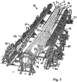
- Fig. 1 shows a perspective view of an embodiment of a bonding device 10 according to the invention, in which an embodiment of a rotor blade 5 according to the invention is added.
- the rotor blade 5 is constructed from three different rotor blade parts 1, 2 and 3.
- the first rotor blade part 1 is designed as a nose shell 1, the second rotor blade part 2 as Mitteilteilsegment 2 and the third rotor blade part 3 as a trailing edge segment 3.
- the adhesive areas 21 between the nose shell 1 and the middle segment 2 are oriented substantially in the longitudinal direction and are both on the Suction as formed on the pressure side of the rotor blade.
- the adhesive areas 22 between the trailing edge segment 1 and the middle segment 2 are oriented substantially in the longitudinal direction and formed both on the suction and on the pressure side of the rotor blade.
- Both the nose shell 1, as well as the trailing edge segment 3 are each connected to the flange 4 by a belt 6, which is anchored in each case in the interior of the nose shell 1, and the trailing edge segment 3.
- the flange 4 is also arranged in a fourth receiving area 14. This arrangement of the flange is done by screwing some of the bolts 4 provided on the flange. By screwing the flange 4 is spatially fixed, so that a movement of the flange 4 would be possible only unintentionally and after spending large mechanical forces.
- an opening 25 which can still ensure access to the interior of the rotor blade 5.
- the opening is required to further process the straps or the webs in the interior of the rotor blade 5.
- the opening 25 is closed with a not further shown component, wherein the outer skin of the rotor blade 5 is attached to the flange 4 on all sides.
- the closing of the opening 25 takes place by bonding the component to the boundaries, which are designed as adhesive areas, with an adhesive to the middle segment 2 and the nose shell 1. Curing by Heat on the adhesive can also be done with a device not shown.
- a first prefabricated rotor blade part 1 (nose cup) is first inserted into the first receptacle 11 of the gluing device 10 and fastened thereto.
- the attachment takes place by means of suitably mounted suction nozzle, which allow a holder by means of negative pressure.
- a third prefabricated rotor blade part 1 (nose cup) is inserted and fastened.
- the attachment is again by mounting by means of negative pressure.
- the recordings 11 and 13 have inserts which correspond to the geometric peripheral shape of the rotor blade parts 1 and 3 and thus support the accurately fitting insertion.
- the inserts are each attached to a first support structure 15 and a third support structure 17.
- the support structures 15 and 17 are each supported on a set of rails 31 against the bottom floor and can be moved towards each other or away from each other.
- a further second holding structure 16 is arranged, on which also a not shown or visible second receiving area 12 is provided.
- the second receiving region 12 serves to receive the second prefabricated rotor blade part 2, which is designed as a middle segment 2, which is arranged in the rotor blade 5 between the nose shell 1 and the trailing edge segment 3.
- the first holding structure 15 with the first rotor blade part 1 (nose cup) accommodated in the first receiving area 11 provided therein and the third holding structure 17 with the third rotor blade part 3 accommodated in the third receiving area 13 provided therein (Trailing edge segment) relative to each other moves, ie both moved to the recorded in the second receiving portion 12 second rotor blade part 2.
- the second receiving area 12 and the second rotor blade part 2 accommodated therein thus remain stationary in space, like the flange 4.
- the movement takes place until the adhesive areas 21 of the nose shell 1 and the adhesive areas 21 of the middle segment 2 are sufficiently in contact with each other. Direct and direct contact can be prevented by the adhesive applied to the gluing areas 21. In any case, however, the approach of both components is sufficiently close to be able to bring about a bonding by means of the adhesive can.
- the movement is made so that the bonding areas 22 of the trailing edge segment 3 and the middle part segment 2 are sufficiently in contact with each other. Direct and direct contact can in turn be prevented by the adhesive applied to the gluing areas 22. In any case, however, the approach of both components is sufficiently close to be able to cause a bond.
- the movement of the first holding structure 15 and the third holding structure 17 can take place at the same time or in a time offset.
- thermal energy is supplied in a localized manner along the two bonding areas 21 and 22 by means of the tempering devices 40, which are respectively provided in the first receiving area 11 and the third receiving area 13.
- the tempering devices 40 are arranged and geometrically designed such that essentially only the adhesive areas 21 and 22 are supplied with thermal energy. This leads to a targeted hardening of the not yet cured adhesive in the adhesive areas 21 and 22 and thus connects the first rotor blade part 1 (nose shell), the second rotor blade part 2 (middle segment) and the third rotor blade part 3 (trailing edge segment) firmly together.
- connection with the flange 4 is also carried out with the first rotor blade part 1 (nose cup), the second rotor blade part 2 (middle part segment) and the third rotor blade part 3 (trailing edge segment), wherein the curing of the adhesive in the non further provided with reference numerals adhesive areas in the present case with a tempering device not shown.
- connection of the belt ends 6 on the side of the first rotor blade part 1 and the third rotor blade part 3 is carried out according to the implementation by means of laterally arranged pressure units 50, which can also be moved in the direction of the flange 4 on rails. After sufficient approach preformed surfaces press against the strap ends 6, which are glued to the flange and thus cause a pressing of the strap ends 6 against predetermined areas on the flange 4. Curing can take place by heat at these areas.
- an annealing device may in turn be provided on or in the pressing regions.
- the movement of both the pressing units 50 and the first holding structure 15 and the third holding structure 17 can be controlled away and individually controlled.
- Fig. 2 shows a perspective side view of the embodiment of a gluing device 10 according to the invention Fig. 1 in which no rotor blade is received.
- the fourth receiving area 14 is shown, which is provided for holding the flange 4.
- the flange 4 is held in this case by means of a few bolts of the bolt rim, which are received by pin receivers 18.
- the bolt receivers 18 are designed as bushings 18, through which the bolts are guided and screwed on the opposite side.
- the second receiving area 12 which itself is mounted on the second holding structure 16 (the second receiving area 12 and the second holding structure 16, which are both arranged in the image plane behind the fourth receiving area 14, are shown in perspective).
- Fig. 3 shows a perspective view of the embodiment of a gluing device 10 according to the invention according to the previous figures, in which no rotor blade 5 is received. It is clearly recognizable in the Representation of the first support structure 15, which has a first receiving portion 11 for receiving a first rotor blade part 1 not shown (nose cup). Furthermore, the third holding structure 17 can be seen, which has a third receiving area 13 for receiving a third rotor blade part 3 (rear edge segment), not shown. Both holding structures 15 and 17 are each arranged on one side of the second receiving area 12, which is mounted on a second holding structure 16.
- a pair of mutually parallel rails 31, which are provided for a respective gluing apparatus 30 (see also FIG Fig. 5 ).
- Such gluing apparatuses can be displaced along these rails 31, so that all gluing areas 21 and 22 of the rotor blade parts 1, 2 and 3 (not shown further) can be supplied and provided with adhesive.
- the rails 31 extend substantially parallel to the longitudinal extension of the second receiving region 12.
- FIG. 3 shows Fig. 3 on the side of the first support structure 15 a set of three pairs of parallel rails 31. These serve the first support structure 15 for movement in the direction of the second receiving portion 12 to.
- a set of four pairs of parallel rails 31 is arranged on the side of the third support structure 17. These also serve the third holding structure 17 for movement in the direction of the second receiving area 12.
- These pairs of rails are arranged in their course substantially perpendicular to the rails 31, which are provided for the gluing apparatus.
- Fig. 4 shows a perspective view of the second receiving portion 12 for receiving a middle segment of an embodiment of a rotor blade according to the invention 5 (not shown) corresponding to the embodiment of the gluing device 10 shown in the preceding figures.
- the second receiving portion 12 is in this case divided into two and is supported by a second support structure 16.
- the fourth receiving area 14 for holding the flange 4 is provided in an extension of the longitudinal extension direction of the second receiving area 12.
- the second receiving area 12 is interrupted approximately in the middle of its longitudinal extent and has a recess. This recess may be advantageous for the adjustment if it has approximately alignment aids, which are not shown here.
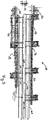
- Fig. 5 shows a perspective view of a gluing apparatus 30 of a not further shown embodiment of the gluing device 10 shown in the preceding figures.
- the gluing device 10 is adapted to accommodate several people (in the present case three persons), which can work on different levels.
- the gluing apparatus 30 has two passenger platforms 35, which can be moved in height (according to the orientation shown).
- the persons may be equipped with hoses (not shown here) which are suitable for application and metering of adhesive (for example commercial epoxy adhesives).
- the hoses can also have suitable outlet nozzles from which the adhesive is dispensed.
- the hoses open on the other side of the hose in an output unit 36, which is provided with a suitable control.
- the dispenser unit 36 cooperates with a pump (not shown) which distributes the ready adhesive to the tubing. From the output unit 36, the tubes each go upwards (according to the present orientation) and are held on a hose holder 38 for strain relief. The adhesive is removed from the reservoir 37.
- the gluing apparatus 30 is supported by rail rollers 39 against rails 31, not shown further, and can be moved approximately autonomously on them by a suitable drive device (not shown).
Landscapes
- Engineering & Computer Science (AREA)
- Mechanical Engineering (AREA)
- Life Sciences & Earth Sciences (AREA)
- Sustainable Development (AREA)
- Sustainable Energy (AREA)
- Chemical & Material Sciences (AREA)
- Combustion & Propulsion (AREA)
- General Engineering & Computer Science (AREA)
- Wind Motors (AREA)
- Lining Or Joining Of Plastics Or The Like (AREA)
Description
Die vorliegende Erfindung betrifft eine Verklebeeinrichtung zum Bau von segmentierten, mindestens drei vorgefertigte Rotorblattteile, nämlich Nasenschale, Mittelteilsegment und Hinterkantensegment, umfassenden Rotorblättern und ein Verfahren zu deren Herstellung.The present invention relates to a gluing device for the construction of segmented, at least three prefabricated rotor blade parts, namely nose cup, middle segment and trailing edge segment, comprehensive rotor blades and a method for their production.
Rotorblätter für Windkraftanlagen werden meist aus einem Laminat aus Glasfaserwerkstoffen und Harzen gefertigt, wobei typischerweise eine Anzahl an flächigen Glasfaserstrukturen mit einem geeigneten Harz infusioniert werden, um einen Verbundwerkstoff mit der Geometrie eines Rotorblattes herzustellen. Um die großmassigen Rotorblätter herzustellen, werden die Glasfaserstrukturen zunächst in geeignete Formen eingelegt und darin mit dem Harz behandelt. Nach einer Wärmebehandlung wird das Harz ausgehärtet und die gesamte Struktur ausgehärtet.Rotor blades for wind turbines are usually made from a laminate of fiberglass materials and resins, typically infusing a number of sheet glass fiber structures with a suitable resin to produce a composite having the geometry of a rotor blade. In order to produce the large-diameter rotor blades, the fiberglass structures are first placed in suitable molds and treated therein with the resin. After a heat treatment, the resin is cured and the entire structure is cured.
Ein Rotorblatt besteht hierbei aus einer Anzahl an verschiedenen Bauteilen, welche alle miteinander verlaminiert bzw. verklebt werden müssen, um die Gesamtstruktur eines Rotorblattes zu realisieren. So umfassen Rotorblätter neben den äußerlich sichtbaren Rotorblattschalen in ihrem Inneren weiterhin noch lastaufnehmende Gurte und Stege, welche mit den Innenflächen der Rotorblattschalen direkt oder indirekt verklebt werden.A rotor blade here consists of a number of different components, which must all be mutually laminated or glued together to realize the overall structure of a rotor blade. Thus, rotor blades in addition to the externally visible rotor blade shells in their interior still load-absorbing straps and webs, which are bonded directly or indirectly to the inner surfaces of the rotor blade shells.
Um die Gesamtstruktur eines Rotorblattes herzustellen, werden die einzelnen Bauteile miteinander verklebt bzw. verlaminiert. Hierbei werden typischerweise mit den Gurten und Stegen bereits versehene Rotorblatthalbschalen (Druckseite und Saugseite) aufeinander aufgebracht, verklebt und nach dem Aushärten des Klebers das Rotorblatt fertig gestellt.In order to produce the overall structure of a rotor blade, the individual components are glued or laminated together. In this case, rotor blade half shells (pressure side and suction side) already provided with the straps and webs are typically applied to one another, bonded and, after the adhesive has cured, the rotor blade is completed.
Das Herstellungsverfahren, welches typischerweise auf einer 2-Formschalentechnologie basiert, weist jedoch Grenzen auf hinsichtlich der darstellbaren Geometrien des Rotorblattes. So erschweren etwa Hinterschnitte und tordierte Blattgeometrien nicht nur das Aufeinanderaufbringen der Rotorblatthalbschalen, sondern auch eine halt- und belastbare Verklebung dieser Stellen wird mit zunehmender Komplexität der Geometrie deutlich erschwert.However, the manufacturing process, which is typically based on a 2-mold shell technology, has limitations with respect to the representable geometries of the rotor blade. For example, undercuts and twisted blade geometries not only make it more difficult for the rotor blade half-shells to be stacked on top of one another, but also a sturdy and durable bond between these points is made more difficult with increasing geometry complexity.
Dieser Umstand gestaltet sich insbesondere als Nachteil beim Bau neuartiger Rotorblattgeometrien, die sich durch eine verstärkte schraubenförmige d. h. tordierte Geometrie auszeichnen. Ferner weisen viele neuartige Blattgeometrien, vor allem im Offshore-Windenergiebereich, solche Rotorblätter mit komplizierten Hinterschnitten und relativ starken Torsionen auf.This circumstance is particularly disadvantageous in the construction of novel rotor blade geometries, which are characterized by a reinforced helical d. H. Distinguish twisted geometry. Furthermore, many novel blade geometries, especially in the offshore wind energy sector, such rotor blades with complicated undercuts and relatively strong torsions.
Die
In der
Die
Die
Demnach stellt es sich als eine technische Notwendigkeit dar, eine Verklebeeinrichtung vorzuschlagen, welche erlaubt, die Nachteile aus dem Stand der Technik beim Bau von Rotorblättern zu vermeiden. Insbesondere sollte die Verklebeeinrichtung auch erlauben, Rotorblattgeometrien zu verwirklichen, die im Vergleich zu herkömmlichen Blattgeometrien stärkere Torsionen und Hinterschnitte aufweisen. Zudem sollte die Verklebeeinrichtung geeignet sein, die Herstellungszeiten für ein Rotorblatt zu vermindern. Eine teilautomatisierte oder sogar vollautomatisierte Herstellung von Rotorblättern sollte ebenfalls ermöglicht werden. Weiterhin ist es Aufgabe der vorliegenden Erfindung, ein Verfahren zur Herstellung eines Rotorblatts vorzuschlagen.Accordingly, it is a technical necessity to propose a gluing device which allows to avoid the disadvantages of the prior art in the construction of rotor blades. In particular, the gluing device should also allow rotor blade geometries to be realized which have stronger torsions and undercuts as compared to conventional blade geometries. In addition, the gluing should be suitable to reduce the manufacturing times for a rotor blade. A partially automated or even fully automated production of rotor blades should also be made possible. It is another object of the present invention to propose a method for producing a rotor blade.
Diese Aufgaben werden gelöst durch eine Verklebeeinrichtung entsprechend Patentanspruch 1. Insbesondere werden diese Aufgaben gelöst durch eine Verklebeeinrichtung zum Bau von segmentierten, mindestens drei vorgefertigte Rotorblattteile, nämlich Nasenschale, Mittelteilsegment und Hinterkantensegment, umfassenden Rotorblättern, aufweisend: einen ersten Aufnahmebereich für die Aufnahme der vorgefertigten Nasenschale, einen zweiten Aufnahmebereich für die Aufnahme des vorgefertigten Mittelteilsegments und einen dritten Aufnahmebereich für die Aufnahme des vorgefertigten Hinterkantensegments, wobei der erste Aufnahmebereich, der zweite Aufnahmebereich und der dritte Aufnahmebereich so relativ zueinander bewegt werden können, dass nach erfolgter Aufnahme der drei vorgefertigten Rotorblattteile in den bestimmungsgemäßen Aufnahmebereichen in einer Offen-Position der Verklebeeinrichtung diese Rotorblattteile über vorbestimmte Verklebebereiche miteinander in direkten oder indirekten Kontakt gebracht und damit in eine Verklebeposition überführt werden können. Erfindungsgemäß ist zwischen einer ersten Haltestruktur für den ersten Aufnahmebereich und einer dritten Haltestruktur für den dritten Aufnahmebereich eine zweite Haltestruktur für den zweiten Aufnahmebereich vorgesehen, wobei die erste Haltestruktur mit dem ersten Aufnahmebereich und der Nasenschale sowie die dritte Haltestruktur mit dem dritten Aufnahmebereich und dem Hinterkantensegment auf das im zweiten Aufnahmebereich aufgenommene Mittelteilsegment zu bewegbar sind, während der zweite Aufnahmebereich mit dem Mittelteilsegment im Raum unbewegt bleibt.These objects are achieved by a gluing device according to claim 1. In particular, these objects are achieved by a gluing device for the construction of segmented, at least three prefabricated rotor blade parts, namely nose shell, middle segment and trailing edge segment, comprehensive rotor blades, comprising: a first receiving area for receiving the prefabricated nose shell a second receiving area for receiving the prefabricated middle segment and a third receiving area for receiving the prefabricated trailing edge segment, wherein the first receiving area, the second receiving area and the third receiving area can be moved relative to each other, that after receiving the three prefabricated rotor blade parts in the intended receiving areas in an open position of the gluing these rotor blade parts over predetermined adhesive areas with each other in direct or indirect Can be brought contact and thus transferred to a gluing position. According to the invention, a second holding structure for the second receiving region is provided between a first holding structure for the first receiving region and a third holding structure for the third receiving region, the first holding structure having the first receiving region and the nose shell and the third holding structure having the third receiving region and the trailing edge segment the central part segment accommodated in the second receiving region can be moved while the second receiving region remains stationary with the middle segment in the space.
Rotorblatteile sind hier auch im Sinne von Rotorblattsegmenten zu verstehen.Rotor blade parts are to be understood here also in the sense of rotor blade segments.
Weiter soll eine Vorfertigung eines Rotorblattteils bereits eine Härtung, d. h. eine Teilhärtung und/oder eine vollständige Aushärtung umfassen. Insbesondere weisen die so vorgefertigten Rotorblattteile einen Glasübergangswert Tg von 50°C auf, was einer Vernetzung von etwa 90% entspricht. Ein weitgehend vollständig ausgehärtetes Rotorblattteil weist hierbei im Gegensatz einen Glasübergangswert Tg von etwa 65°C auf. Die Messung des Glasübergangswertes erfolgt typischerweise mit der Dynamisch Mechanischen Analyse (DMA) oder der dynamischen Differenzkalorimetrie (DSC).Furthermore, a prefabrication of a rotor blade part should already comprise a hardening, ie a partial hardening and / or a complete hardening. In particular, they are so prefabricated rotor blade parts to a glass transition value Tg of 50 ° C, which corresponds to a cross-linking of about 90%. In contrast, a largely completely hardened rotor blade part in this case has a glass transition value Tg of about 65 ° C. The glass transition value is typically measured by Dynamic Mechanical Analysis (DMA) or Differential Scanning Calorimetry (DSC).
Weiter zeichnet sich die Verklebeposition dadurch aus, dass sie eine Position darstellt, welche geeignet ist, die Rotorblattteile miteinander zu verkleben. Hierbei kann die Verklebeposition mit einer Schließposition der Verklebeeinrichtung übereinstimmen oder aber auch eine Position sein, welche nicht mit einer Schließposition der Verklebeeinrichtung übereinstimmt, jedoch mit einer Position, die für eine Verklebung geeignet ist.Furthermore, the adhesive position is characterized in that it represents a position which is suitable for bonding the rotor blade parts together. In this case, the adhesive bonding position may coincide with a closing position of the bonding device or may also be a position which does not coincide with a closing position of the bonding device, but with a position which is suitable for bonding.
Gemäß einer besonders bevorzugten Ausführungsform sind die Rotorblatteile Bauteile, welche von außen an dem fertig gestellten Rotorblatt zugänglich sind, d. h. sie weisen wenigstens bereichsweise einen Außenhautabschnitt auf. Insbesondere sind die Rotorblattteile nicht nur Gute oder Stege, wohingegen Gute und/oder Stege von den Rotorblattteilen mit umfasst sein können.According to a particularly preferred embodiment, the rotor blade parts are components that are accessible from the outside on the finished rotor blade, d. H. they have at least partially an outer skin section. In particular, the rotor blade parts are not only good or webs, whereas good and / or webs can be included by the rotor blade parts.
Ferner sind die Verklebebereiche am Rotorblatt von außen wenigstens bereichsweise nach dessen Herstellung sichtbar, d. h. wenigstens eine Verklebungsnaht ist von außen sichtbar. Insbesondere betreffen die Verklebebereiche nicht Verklebungen der Bauteile, beispielsweise wie Gurt oder Steg, welche nach Fertigstellung des Rotorblatts von außen nicht mehr sichtbar oder zugänglich sind.Furthermore, the bonding areas on the rotor blade from the outside at least partially visible after its production, d. H. at least one glued seam is visible from the outside. In particular, the adhesive areas do not affect adhesions of the components, for example, such as belt or web, which are no longer visible or accessible from the outside after completion of the rotor blade.
Ferner werden die Erfindungsaufgaben durch ein Verfahren zum Verkleben nach Patentanspruch 12 gelöst. Insbesondere werden die Aufgaben durch ein Verfahren zum Verkleben von mindestens drei vorgefertigten Rotorblattteilen, nämlich Nasenschale, Mittelteilsegment und Hinterkantensegment, zum Bau eines segmentierten Rotorblattes gelöst, wobei die Rotorblatteile mit Hilfe einer Verklebeeinrichtung derart verklebt werden, dass alle drei Rotorblattteile von der Verklebeeinrichtung aufgenommen und über vorbestimmte Verklebebereiche mit einem anderen Rotorblattteil in direktem oder indirektem Kontakt zum Verkleben in eine Verklebeposition überführt werden. Erfindungsgemäß werden eine erste Haltestruktur mit einem ersten Aufnahmebereich und der Nasenschale sowie eine dritte Haltestruktur mit einem dritten Aufnahmebereich und dem Hinterkantensegment auf das Mittelteilsegment zu bewegt, während ein zweiter Arbeitsbereich mit dem Mittelteilsegment im Raum unbewegt bleibt.Furthermore, the invention tasks are solved by a method for bonding according to
Eine derartige Verklebeeinrichtung sowie das entsprechende Herstellungsverfahren solcher Rotorblätter erlaubt eine Vielzahl an vorgefertigten Rotorblattteilen in geeigneter Weise miteinander zu verkleben, um eine Rotorblattgeometrie zu realisieren, die sich durch sonst derzeit nicht herzustellende Torsionen und Hinterschnitte auszeichnet. Indem nämlich die Rotorblattteile nicht nur aus zwei Halbschalen hergestellt werden, können die einzelnen Rotorblattteile mit einer derartigen Geometrie vorgefertigt werden, dass das zeitlich nachfolgende Fügen und Verkleben der einzelnen Rotorblattteile deutlich erleichtert ist. Demnach können auch die Rotorblattteile, welche eine verstärkte Torsion oder eine Hinterschnitt aufweisen, vorgefertigt werden, ohne dass sie bereits mit einem anderen Rotorblattteil verbunden sind.Such a gluing device as well as the corresponding production method of such rotor blades allows a multiplicity of prefabricated rotor blade parts to be glued together in a suitable manner in order to realize a rotor blade geometry which is distinguished by torsions and undercuts that can not otherwise be produced. Because the rotor blade parts are not only produced from two half shells, the individual rotor blade parts can be prefabricated with such a geometry that the temporally subsequent joining and gluing of the individual rotor blade parts is significantly facilitated. Accordingly, the rotor blade parts, which have a reinforced torsion or an undercut, can be prefabricated, without that they are already connected to another rotor blade part.
Erfindungsgemäß erlaubt das Herstellungsverfahren bzw. die Verklebeeinrichtung, sich von der bisherigen 2-Halbschalenfertigung zu lösen und ermöglicht damit eine Herstellung von Rotorblättern mit komplexen Geometrien.According to the invention, the manufacturing method or the gluing device allows to detach from the previous 2-half-shell production and thus enables a production of rotor blades with complex geometries.
Ein solches erfindungsgemäßes Herstellungsverfahren sowie Verklebeeinrichtung erlauben also die Herstellung sog. Multisegmentblätter, die sich zudem durch größere Dimensionen als herkömmliche, bisher aus dem Stand der Technik bekannte Rotorblätter sowie durch eine größere Anzahl an möglichen geometrischen Ausgestaltungen auszeichnen. Aufgrund der erfindungsgemäßen Verklebeeinrichtung wird zudem der Arbeitsaufwand beim Verkleben solcher Rotorblätter vermindert, so dass eine beschleunigte Herstellung von dem Zeitpunkt der Verklebung bis zum Zeitpunkt der Fertigstellung des Rotorblattes resultieren kann. Zudem erlaubt die Verklebeeinrichtung auch eine geeignete Bauteilpositionierung, um auch komplexere Rotorblattgeometrien realisieren zu können. Weiterhin wird der der Herstellung zeitlich vorgelagerte logistische Arbeitsaufwand vermindert, indem nämlich hinsichtlich ihrer Dimensionen relativ kleinere Rotorblattteile zu transportieren sind.Such a production method according to the invention as well as a gluing device thus allow the production of so-called multi-segment sheets which are also distinguished by larger dimensions than conventional rotor blades hitherto known from the prior art and by a larger number of possible geometric configurations. Due to the gluing device according to the invention, moreover, the labor involved in gluing such rotor blades is reduced, so that an accelerated production of the time the bonding can result until the time of completion of the rotor blade. In addition, the gluing device also allows a suitable component positioning in order to realize even more complex rotor blade geometries. Furthermore, the logistical workload upstream of the production is reduced, namely by relatively smaller rotor blade parts having to be transported with regard to their dimensions.
Entsprechend einer ersten besonders bevorzugten Ausführungsform der Verklebeeinrichtung ist vorgesehen, dass die Verklebeeinrichtung wenigstens einen weiteren vierten Aufnahmebereich aufweist, welcher zur Aufnahme bzw. zur Halterung eines Flansches ausgebildet ist, der insbesondere mit mindestens einem der drei vorgefertigten Rotorblattteilen über einen vorbestimmten Verklebebereich verklebt werden kann. Damit ist gewährleistet, dass ausführungsgemäß ein gesamtes Rotorblatt mit Flansch zum Anschluss an eine Nabe einer Windkraftanlage hergestellt werden kann. Zudem gewährleistet der vierte Aufnahmebereich eine kontrollierte Manipulation des Flansches, um eine gewünschte Ausrichtung und exakte relative Positionierung der Rotorblattteile zum Flansch zu erreichen. Zudem kann eine separate Aufnahme des Flansches in einem Bereich, welcher nicht zur Aufnahme anderer relativ leichterer Rotorblatteile vorgesehen ist, eine verbesserte Gewichtsverteilung erreichen, wodurch der technische Gesamtaufwand für die Verklebeeinrichtung vermindert werden kann.According to a first particularly preferred embodiment of the gluing device, it is provided that the gluing device has at least one further fourth receiving area, which is designed to receive or hold a flange, which can in particular be glued to at least one of the three prefabricated rotor blade parts over a predetermined gluing area. This ensures that, according to the embodiment, an entire rotor blade with flange can be produced for connection to a hub of a wind power plant. In addition, the fourth receiving area ensures controlled manipulation of the flange to achieve a desired orientation and exact relative positioning of the rotor blade parts to the flange. In addition, a separate recording of the flange in an area which is not intended to accommodate other relatively lighter rotor blade parts, achieve an improved weight distribution, whereby the overall technical effort for the gluing device can be reduced.
Entsprechend einer weiteren Ausführungsform der erfindungsgemäßen Verklebeeinrichtung kann vorgesehen sein, dass die Überführung der in den drei Aufnahmebereichen angeordneten, vorgefertigten Rotorblattteile in die Verklebeposition automatisch, und/oder weggesteuert erfolgt. Dies ermöglicht einerseits eine zeitlich schnellere Herstellung eines fertigen Rotorblatts, zudem kann damit eine Serienfertigung für relativ große Durchlaufmengen erreicht werden. Eine Wegsteuerung ermöglicht zudem noch die Genauigkeit und Exaktheit, mit welcher die Rotorblatteile miteinander verklebt sind, zu erhöhen. Weiterhin ist die Positionier- und Widerholgenauigkeit deutlich verbessert.According to a further embodiment of the gluing device according to the invention, it can be provided that the transfer of the prefabricated rotor blade parts arranged in the three receiving regions into the gluing position takes place automatically and / or controlled by path. On the one hand, this makes it possible to produce a finished rotor blade faster in terms of time; in addition, mass production for relatively large throughput quantities can thus be achieved. A path control also makes it possible to increase the accuracy and accuracy with which the rotor blade parts are glued together. Furthermore, the positioning and repeat accuracy is significantly improved.
Weiterhin kann ausführungsgemäß vorgesehen sein, dass der erste Aufnahmebereich, der zweite Aufnahmebereich und der dritte Aufnahmebereich bei der Überführung der in den drei Aufnahmebereichen angeordneten, vorgefertigten Rotorblattteile in die Verklebeposition derart bewegt werden können, dass die vorgefertigten Rotorblattteilen im Wesentlichen gleichzeitig, insbesondere aber nicht mit einem größeren Zeitversatz als 30 min miteinander zum Verkleben in direkten oder indirekten Kontakt gebracht werden können. Demnach ist wiederum eine relativ schnellere Herstellung eines fertigen Rotorblatts ermöglicht und die Grundlage einer Serienproduktion gewährleistet. Insbesondere ist damit auch die Realisierung eines 12-Stunden-Takes bei der Herstellung der Rotorblätter möglich, da ein zeitlich unmittelbar aufeinander folgendes Zusammenfügen der Rotorblattteile Zeit für die Fertigstellung eines Rotorblattes verringert.Furthermore, according to the embodiment, provision may be made for the first receiving area, the second receiving area and the third receiving area to be included the transfer of arranged in the three receiving areas, prefabricated rotor blade parts can be moved into the adhesive position such that the prefabricated rotor blade parts substantially simultaneously, but not in particular with a greater time offset than 30 minutes with each other for direct bonding or indirect contact can be made. Accordingly, in turn, a relatively faster production of a finished rotor blade is possible and ensures the basis of mass production. In particular, the realization of a 12-hour take in the production of the rotor blades is thus possible, since a temporally directly successive joining the rotor blade parts reduces time for the completion of a rotor blade.
Entsprechend einer weiteren Ausführungsform der erfindungsgemäßen Verklebeeinrichtung ist vorgesehen, dass wenigstens einer der vier Aufnahmebereiche bei der Überführung der in den vier Aufnahmebereichen angeordneten, vorgefertigten Rotorblattteile in die Verklebeposition relativ zu einem der anderen Aufnahmebereiche verkippt werden kann. Damit sind bisher nicht herstellbare Hinterschnitte realisierbar, welche noch komplexere Blattgeometrien zu bauen erlauben. Insbesondere sind die Anstellwinkel bei der Verkippung individuell einstellbar.According to a further embodiment of the gluing device according to the invention, it is provided that at least one of the four receiving regions can be tilted relative to one of the other receiving regions during the transfer of the prefabricated rotor blade parts arranged in the four receiving regions into the gluing position. Thus, not yet producible undercuts are feasible, which allow to build even more complex blade geometries. In particular, the angle of attack during tilting are individually adjustable.
Entsprechend einer weiteren Ausführungsform der Erfindung ist vorgesehen, dass der erste Aufnahmebereich, der zweite Aufnahmebereich und der dritte Aufnahmebereich bei der Überführung der in den drei Aufnahmebereichen angeordneten, vorgefertigten Rotorblattteile in die Verklebeposition eine in Bezug zum Verlauf des Erbeschleunigungsfeldes senkrechte Bewegung relativ zueinander ausführen. Die Relativbewegung erfolgt also im Wesentlichen horizontal, wobei die drei Rotorblatteile aufgrund dieser Horizontalbewegung so zueinander und in eine Verklebeposition bewegt werden, dass die zu verklebenden Rotorblattteile vor, während und auch nach dem Bewegen in die Verklebeposition leicht von Bedienungspersonal überwacht und kontrolliert werden können. Zudem erfordert eine Horizontalbewegung relativ weniger Kraft- und damit Energieaufwand, als eine Bewegung, die eine Vertikalbewegungskomponente aufweist. Dies gewährleistet somit einen im Wesentlichen geringen Energieverbrauch als andere Bewegungsorientierungen. Alternativ kann die Bewegung auch parallel zueinander erfolgen, wobei sich hierbei entsprechende Nachteile ergeben.According to a further embodiment of the invention, it is provided that the first receiving area, the second receiving area and the third receiving area carry out a movement relative to one another with respect to the course of the acceleration field when transferring the prefabricated rotor blade parts arranged in the three receiving areas into the gluing position. The relative movement therefore takes place essentially horizontally, the three rotor blade parts being moved relative to one another and into a gluing position due to this horizontal movement so that the rotor blade parts to be glued can be easily monitored and controlled by operating personnel before, during and also after moving into the gluing position. In addition, a horizontal movement requires relatively less force and thus energy expenditure, than a movement having a vertical movement component. This thus ensures a substantially low energy consumption than others Movement orientations. Alternatively, the movement can also take place parallel to one another, resulting in corresponding disadvantages.
Entsprechend einer weiteren möglichen Ausführungsform ist vorgesehen, dass der in dem vierten Aufnahmebereich angeordnete bzw. gehalterte Flansch bei der Überführung der in den ersten, zweiten und dritten Aufnahmebereichen angeordneten, vorgefertigten Rotorblattteile in die Verklebeposition ortsfest und unbewegt bleibt. Dies ermöglicht einerseits eine genauere relative Positionierung des Flansches relativ zu den Rotorblatteilen, da eine Bewegung des relativ schwereren Flanschbereichs vermieden werden kann. Zudem wird dadurch auch das Gesamtfertigungsverfahren vereinfacht, da nur die Bewegungen und damit die relative Positionierung der Rotorblatteile in Bezug auf ein festes Bezugssystem (nämlich das des Flansches) berücksichtigt werden müssen. Der Flansch ist typischerweise zudem noch in seiner Position vorjustiert, so dass eine Anordnung aller Rotorblatteile relativ zu dem Flansch die Gesamtausrichtung und genaue Anordnung der Rotorblatteile zueinander erleichtert. Diese Vorteile lassen sich auch in Bezug auf eine alternative Ausführungsform feststellen, bei welcher der Flansch mit einem der wenigstens drei Rotorblattteile bereits fest verbunden ist.In accordance with a further possible embodiment, it is provided that the prefabricated rotor blade parts arranged in the fourth receiving region remain stationary and unmoved in the adhesive position during the transfer of the prefabricated rotor blade parts arranged in the first receiving region. This allows on the one hand a more accurate relative positioning of the flange relative to the rotor blade parts, since movement of the relatively heavier flange portion can be avoided. In addition, this also simplifies the overall production process, since only the movements and thus the relative positioning of the rotor blade parts with respect to a fixed reference system (namely that of the flange) must be taken into account. The flange is also typically pre-adjusted in position so that an arrangement of all the rotor blades relative to the flange facilitates the overall alignment and location of the rotor blades relative to one another. These advantages can also be determined in relation to an alternative embodiment, in which the flange is already firmly connected to one of the at least three rotor blade parts.
Entsprechend einer weiteren bevorzugten Ausführungsform kann auch vorgesehen sein, dass der erste Aufnahmebereich, der zweite Aufnahmebereich und der dritte Aufnahmebereich derart zueinander angeordnet sind, dass das zu bauende segmentierte Rotorblatt nach der Überführung der in den drei Aufnahmebereichen angeordneten, vorgefertigten Rotorblattteile in die Verklebeposition entweder mit seiner Saugseite oder mit seiner Druckseite im Wesentlichen parallel zum Verlauf der Erdoberfläche orientiert ist, auf welcher insbesondere die Verklebeeinrichtung aufgestellt ist. Damit ist eine optisch unterstützte Justierung der einzelnen Rotorblattteile erleichtert. Zudem können die einzelnen Rotorblattteile geeignet gegen den Boden abgestützt werden, ohne Beschädigungen an den Rotorblattteilen oder eine Veränderung ihrer relativen Ausrichtung befürchten zu müssen.According to a further preferred embodiment, it can also be provided that the first receiving area, the second receiving area and the third receiving area are arranged relative to one another such that the prefabricated rotor blade parts arranged in the three receiving areas are transferred to the segmented rotor blade to be built into the gluing position either with its suction side or with its pressure side is oriented substantially parallel to the course of the earth's surface, on which in particular the gluing device is set up. For an optically supported adjustment of the individual rotor blade parts is facilitated. In addition, the individual rotor blade parts can be suitably supported against the ground, without having to fear damage to the rotor blade parts or a change in their relative orientation.
Entsprechend einer weiteren Ausführungsform der Verklebeeinrichtung kann auch vorgesehen sein, dass wenigstens einer der drei Aufnahmebereiche schwenkbar, insbesondere um wenigstens 90° schwenkbar ausgeführt ist. Damit können etwa Verklebebereiche der einzelnen Rotorblattteile für das Bedienpersonal zugänglich gemacht werden, welche andererseits nur schwer zu erreichen wären. So können etwa bestimmte Rotorblatteile für den erforderlichen Kleberauftrag in ihrer Position verändert werden, und anschließend zum Verkleben mit weiteren Rotorblattteilen wieder in eine Ausrichtung überführt werden. Nicht nur zum Kleberauftrag kann jedoch eine Verschwenkung erfolgen, sondern auch etwa zum Befüllen der Aufnahmen der Verklebeeinrichtung mit den entsprechenden vorgefertigten Rotorblattteilen. Hierbei erweist es sich als besonders vorteilhaft, wenn eine Schwenkposition eine der Aufnahmen nach oben, entgegen der Richtung der Schwerkraft, frei gibt.According to a further embodiment of the gluing device can also be provided that at least one of the three receiving areas is pivotable, in particular by at least 90 ° pivotable. This can be about Glueing areas of the individual rotor blade parts are made available to the operating personnel, which would be difficult to achieve on the other hand. Thus, for example, certain rotor blade parts for the required application of adhesive can be changed in their position, and then transferred again for bonding with other rotor blade parts in an orientation. However, not only for adhesive application can be made a pivoting, but also about to fill the recordings of the gluing device with the corresponding prefabricated rotor blade parts. It proves to be particularly advantageous if a pivot position, one of the shots upwards, against the direction of gravity, free.
Entsprechend einer weiteren Ausführungsform kann vorgesehen sein, dass wenigstens einer der Aufnahmebereiche an eine geometrische Form des bestimmungsgemäß zur Aufnahme vorgesehenen, vorgefertigten Rotorblattteils bzw. Flansches anpassbar ist. Damit ist es möglich, die Verklebeeinrichtung auch für die Herstellung von Rotorblättern zu verwenden, die eine abweichende Geometrie aufweisen. Insbesondere sind die jeweiligen Aufnahmen für die Aufnahme der Rotorblattteil mit Einsätzen versehen, welche sich der Geometrie des Rotorblattteils anpasst bzw. dieser entspricht. Soll nun die Geometrie des Rotorblattes verändert werden, ist es lediglich erforderlich, diese Einsätze auszutauschen, um Aufnahmen bereitstellen zu können, welche auch der neuen Geometrie entsprechen. Alternativ können auch die Einsätze durch geeignet angebrachte Aktuatoren entsprechend verformt und damit angepasst werden. Folglich wird ausführungsgemäß die Benutzungsvielseitigkeit der Verklebeeinrichtung erhöht.According to a further embodiment it can be provided that at least one of the receiving areas is adaptable to a geometric shape of the intended intended for receiving, prefabricated rotor blade part or flange. This makes it possible to use the gluing device also for the production of rotor blades, which have a different geometry. In particular, the respective receptacles for receiving the rotor blade part are provided with inserts which adapts to or corresponds to the geometry of the rotor blade part. Now, if the geometry of the rotor blade to be changed, it is only necessary to replace these inserts to provide shots, which also correspond to the new geometry. Alternatively, the inserts can also be appropriately deformed and adapted by suitably mounted actuators. Thus, according to the embodiment, the versatility of use of the gluer is increased.
Entsprechend einer weiteren Ausführungsform der erfindungsgemäßen Verklebeeinrichtung ist auch vorgesehen, dass der erste Aufnahmebereich für die Aufnahme einer vorgefertigten Nasenschale und/oder der zweite Aufnahmebereich für die Aufnahme eines vorgefertigten Mittelteilsegments und/oder der dritte Aufnahmebereich für die Aufnahme eines vorgefertigten Hinterkantensegments des zu bauenden Rotorblatts vorgesehen ist. Diese Rotorblattteile sind insbesondere so miteinander verklebt, dass ihre Verklebebereiche größtenteils in Längsrichtung des herzustellenden Rotorblatts angeordnet sind bzw. verlaufen. Zudem weist der Bereich des Rotorblatts, welcher als Nasenbereich bezeichnet wird, eine mitunter verstärkte Krümmung und Torsion auf. Dies ist insbesondere auch für den Bereich zutreffend, welcher als Hinterkante des Rotorblattes bezeichnet wird. Um folglich Probleme bei der Herstellung und dem nachfolgenden Fügen zu verringern bzw. auszuschließen, werden Rotorblattteile, welche diese bereiche umfassen, vorgefertigt und nachfolgend nur noch in geeigneter Weise verklebt. Die Verklebung kann hierbei in Verklebebereichen erfolgen, welche für eine feste Klebeverbindung besser geeignet sind, als die mitunter gekrümmten Bereiche in dem Nasenbereich sowie dem Hinterkantenbereich.According to a further embodiment of the gluing device according to the invention, it is also provided that the first receiving area for receiving a prefabricated nose cup and / or the second receiving area for receiving a prefabricated middle section and / or the third receiving area for receiving a prefabricated trailing edge segment of the rotor blade to be constructed is. These rotor blade parts are glued together in particular so that their adhesive areas are largely arranged or extend in the longitudinal direction of the rotor blade to be produced. In addition, the area of the rotor blade, which is referred to as the nose area, one sometimes increased curvature and torsion. This is especially true for the area which is referred to as the trailing edge of the rotor blade. Consequently, in order to reduce or eliminate problems during manufacture and subsequent joining, rotor blade parts which comprise these areas are prefabricated and subsequently glued only in a suitable manner. The bonding can in this case take place in adhesive areas, which are better suited for a fixed adhesive bond than the sometimes curved areas in the nose area and the trailing edge area.
Ausführungsgemäß kann auch vorgesehen sein, dass wenigstens einer der ersten, zweiten oder dritten Aufnahmebereiche des zu bauenden Rotorblatts eine Längserstreckung aufweisen, welche im Wesentlichen parallel zur Längserstreckung des zu bauenden Rotorblatts orientiert ist. Die Längserstreckung des Rotorblattes erstreckt sich hierbei von dem Flansch des Rotorblattes zu der Blattspitze. Die ausführungsgemäße Verklebeeinrichtung weist zudem eine oder mehrere Aufnahmen auf, deren geometrische Erstreckung eine Ausdehnungsrichtung aufweist, die sich von den anderen dadurch unterscheidet, dass sie maximal groß ist. Dies soll im ausführungsgemäßen Sinne die Längserstreckungsrichtung der Aufnahme sein. Alternativ können die Aufnahmebereiche auch eine Längserstreckung aufweisen, welche senkrecht zu der Längserstreckungsrichtung des zu bauenden Rotorblatts bzw. in einem vorbestimmten Winkel dazu verlaufen.According to the embodiment, it may also be provided that at least one of the first, second or third receiving areas of the rotor blade to be constructed has a longitudinal extent which is oriented substantially parallel to the longitudinal extent of the rotor blade to be constructed. The longitudinal extent of the rotor blade extends from the flange of the rotor blade to the blade tip. In addition, the gluing device according to the invention has one or more receptacles whose geometric extension has an expansion direction which differs from the others in that it is maximally large. This should be in the embodiment according to the direction of elongation of the recording. Alternatively, the receiving areas can also have a longitudinal extension, which run perpendicular to the longitudinal direction of the rotor blade to be built or at a predetermined angle thereto.
Weiter kann im Sinne einer weiteren Ausführungsform vorgesehen sein, dass die Verklebeeinrichtung eine Verklebeapparatur aufweist, welche wenigstens abschnittsweise entlang der vorbestimmten Verklebebereiche, insbesondere senkrecht zu der Verlaufsrichtung des Erdmagnetfelds entlang der vorbestimmten Verklebebereiche verfahrbar ist. Die Verklebeapparatur ermöglicht den Auftrag des erforderlichen Klebers auf die Verklebebereiche vor dem Zusammenfügen der Rotorblattteile. Aufgrund der Größe der Rotorblatteile sowie der entsprechenden Verklebebereiche ist der Auftrag von großen Mengen von Kleber erforderlich, welcher ausführungsgemäß aus Gründen der Zeit- und Fertigungseffizienz mit Hilfe der Verklebeapparatur aufgetragen wird. Hierbei kann der Kleberauftrag durch menschliche Einwirkung unterstützt aufgetragen werden, oder aber vollständig automatisch.Furthermore, it can be provided in the sense of a further embodiment that the gluing device has a gluing apparatus which can be moved at least in sections along the predetermined gluing areas, in particular perpendicular to the course of the earth's magnetic field along the predetermined gluing areas. The gluing apparatus allows the application of the required adhesive to the gluing areas prior to assembly of the rotor blade parts. Due to the size of the rotor blade parts and the corresponding adhesive areas, it is necessary to apply large quantities of adhesive, which according to the embodiment is applied with the aid of the gluing apparatus for reasons of time and production efficiency. Here, the adhesive application can be applied supported by human intervention, or completely automatically.
Gemäß einer Weiterführung dieser Ausführungsform kann auch vorgesehen sein, dass die Verklebeapparatur geeignet ist, wenigstens eine Person aufzunehmen, die einen Kleberauftrag auf die vorbestimmten Verklebebereiche wenigstens eines der vorgefertigten Rotorblattteile vornehmen bzw. überwachen kann. Die wenigstens eine Person gewährleistet einen geeigneten Kleberauftrag auf die Verklebebereiche. Sie trägt entweder durch Handhabung einer geeigneten Vorrichtung den Kleber auf die erforderlichen Verklebebereiche auf oder aber überwacht nur den Kleberauftrag im Falle einer automatisch bzw. teilautomatisch betriebenen Vorrichtung. Insbesondere weist die Verklebeapparatur auch ausreichend Raum für die Lagerung des Klebers auf. Als Kleber kann ein industrieüblicher Kleber, insbesondere ein Epoxykleber verwendet werden.According to a continuation of this embodiment, it can also be provided that the gluing apparatus is suitable for accommodating at least one person who can undertake or monitor an adhesive application to the predetermined gluing areas of at least one of the prefabricated rotor blade parts. The at least one person ensures a suitable application of adhesive to the gluing areas. It either by applying a suitable device, the adhesive on the required adhesive areas on or monitored only the adhesive application in the case of an automatic or semi-automatic device operated. In particular, the gluing apparatus also has sufficient space for the storage of the adhesive. The adhesive used may be an industrial adhesive, in particular an epoxy adhesive.
Weiterhin kann die Verklebeapparatur auch in die Längserstreckungsrichtung des zu bauenden Rotorblatts verfahrbar sein. Damit wird insbesondere dann besonders effizient Kleber aufgebracht, wenn die Rotorblattteile eine Längserstreckungsrichtung aufweisen, welche im Wesentlichen der Längserstreckungsrichtung des herzustellenden Rotorblatts entspricht, also die Verklebebereiche ebenfalls in diese Längserstreckungsrichtung verlaufen.Furthermore, the gluing apparatus can also be moved in the longitudinal direction of the rotor blade to be built. In this way, adhesive is applied in a particularly efficient manner, in particular, when the rotor blade parts have a longitudinal direction which corresponds essentially to the direction of longitudinal extent of the rotor blade to be produced, that is to say the adhesive areas likewise extend in this longitudinal direction.
Weiterhin kann die Verklebeapparatur sich auch dadurch auszeichnen, dass die Verklebeapparatur dafür geeignet ausgebildet ist, Kleber auf vorbestimmte Verklebebereiche wenigstens eines der vorgefertigten Rotorblattteile bzw. den Flansch automatisch aufzutragen. Ein solcher automatischer Auftrag kann etwa dadurch erfolgen, dass die Verklebebereiche eine geeignete Kennzeichnung aufweisen, welche von einer optischen Erkennung erfasst werden und entsprechend mit Kleber versorgt werden. Alternativ kann ein solcher automatischer Auftrag auch dadurch erfolgen, dass die Ausmaße und Ortspositionen der Verklebebereiche vorab erfasst und abgespeichert werden, und die Verklebeapparatur entsprechend diesen abgespeicherten Informationen einen ortsgenauen Kleberauftrag ermöglicht.Furthermore, the gluing apparatus can also be distinguished by the fact that the gluing apparatus is designed to apply adhesive to predetermined gluing areas of at least one of the prefabricated rotor blade parts or the flange automatically. Such an automatic application can take place, for example, by virtue of the fact that the adhesive areas have suitable identification, which are detected by an optical recognition and supplied with adhesive in a corresponding manner. Alternatively, such an automatic job can also take place in that the dimensions and spatial positions of the gluing areas are recorded and stored in advance, and the gluing apparatus enables a locally accurate application of glue in accordance with this stored information.
Entsprechend einer weiteren Ausführungsform der Verklebeeinrichtung kann auch vorgesehen sein, dass die Verklebeeinrichtung wenigstens eine Tempervorrichtung aufweist, welche derart ausgebildet ist, dass sie lokal begrenzt, vorbestimmte Verklebebereiche wenigstens eines der vorgefertigten Rotorblattteile bzw. des Flansches mit Wärme beaufschlagt. Eine solche Tempervorrichtung kann eine Widerstandheizung mit metallischen Widerstandsheizdrähten aufweisen. Diese können auch in vorbestimmte Bauteile, insbesondere in Einsätze der Aufnahmebereiche für die vorgefertigten Rotorblattteile einlaminiert sein. Derartige Widerstandsheizfelder können die Größe von 1 - 2 m2 aufweisen, die einzeln bzw. separat ansteuerbar sind. Zur Temperaturregelung sind zudem noch Temperaturmessfühler vorgesehen. Die Geometrie der Tempervorrichtung entspricht hierbei im Wesentlichen dem Verlauf der Verklebebereiche, wobei andere vorgefertigte und bereits gehärtete Bereiche der Rotorblattteile nicht mit Wärmeenergie versorgt wird. Dies spart vor allem im Vergleich zu solchen Verklebeeinrichtungen merkbar Energie, da nicht das gesamte herzustellende Rotorblatt mit Wärmeenergie versorgen wird.According to a further embodiment of the gluing device, it can also be provided that the gluing device has at least one tempering device which is designed such that it defines locally, predetermined Adhesive areas of at least one of the prefabricated rotor blade parts or the flange with heat applied. Such a tempering device may have a resistance heating with metallic resistance heating wires. These can also be laminated into predetermined components, in particular in inserts of the receiving areas for the prefabricated rotor blade parts. Such resistance heating fields can have the size of 1 to 2 m 2 , which can be controlled individually or separately. For temperature control temperature sensors are also provided. In this case, the geometry of the tempering device essentially corresponds to the course of the adhesive areas, with other prefabricated and already hardened areas of the rotor blade parts not being supplied with thermal energy. This saves noticeably energy, especially in comparison to such gluing devices, since not all of the rotor blade to be produced is supplied with heat energy.
Weiter kann die Verklebevorrichtung auch noch mindestens eine Andrückeinheit aufweisen, welche derart ausgebildet ist, dass sie ein oder mehrere Gurtenden der vorgefertigten Rotorblattteile zum Verkleben an den Flansch andrücken kann. Eine solche Anrückeinheit ermöglicht vor allem eine gezielte Verbindung von Rotorblattteil und Flansch. Das Rotorblattteil weist etwa ausführungsgemäß Gurte auf, welche nach abschließender Fertigstellung des Rotorblatt im Inneren angeordnet sind. Alternativ kann aber auch jeder andere geeignete Bereich eines oder mehrerer Rotorblatteile an den Flansch angedrückt werden. Eine solche Andrückeinheit kann zudem auch eine Tempervorrichtung mit umfassen.Furthermore, the gluing device may also have at least one pressing unit, which is designed such that it can press one or more strap ends of the prefabricated rotor blade parts for gluing to the flange. Such an Anrückeinheit allows especially a targeted connection of rotor blade part and flange. The rotor blade part has about execution in accordance straps, which are arranged after final completion of the rotor blade inside. Alternatively, however, any other suitable area of one or more rotor blade parts can be pressed against the flange. Such a pressure unit may also include a tempering device.
Überdies kann die Verklebevorrichtung auch noch mindestens eine Ansaugeinheit aufweisen, welche erlaubt, wenigstens eines der Rotorblattteile mittels Unterdruck in dem jeweiligen Aufnahmebereich zu haltern. Hierzu kann die Verklebevorrichtung in den jeweiligen Aufnahmebereichen Ansaugstutzen aufweisen, welche mit wenigstens einer Saugpumpe zusammen wirken und zwischen dem vorgefertigten Rotorblattteil und dem Aufnahmebereich ein Vakuum ausbilden. Eine derartige Halterung hinterlässt auf der Oberfläche der Rotorblattteil keine Beschädigungen und eignet sich damit besonders gut für die Halterung.Moreover, the gluing device can also have at least one suction unit, which allows to support at least one of the rotor blade parts by means of negative pressure in the respective receiving area. For this purpose, the Verklebevorrichtung may have suction in the respective receiving areas, which cooperate with at least one suction pump and form a vacuum between the prefabricated rotor blade part and the receiving area. Such a holder leaves no damage on the surface of the rotor blade part and is therefore particularly well suited for the holder.
Entsprechend einer weiteren Ausführungsform des erfindungsgemäßen Verfahrens zur Herstellung eines Rotorblatts kann auch vorgesehen sein, dass die Überführung der Rotorblattteile in die Verklebeposition weggesteuert erfolgt. Wie oben schon ausgeführt, ermöglicht dies eine zeitlich verbesserte und genauere Herstellung des Rotorblatts. Bevorzugt erfolgt die Wegsteuerung mit einer Genauigkeit von wenigstens 1 cm, insbesondere von 0,5 cm und bevorzugt von wenigstens 3 mm. Damit können die Verklebebereiche der Rotorblattteile mit ausreichender Genauigkeit zueinander positioniert werden, um die erforderliche Maßhaltigkeit des Rotorblatts gewährleisten zu können.In accordance with a further embodiment of the method according to the invention for producing a rotor blade, it can also be provided that the transfer of the rotor blade parts into the adhesive bonding position takes place in a controlled way. As already stated above, this enables a temporally improved and more accurate production of the rotor blade. The path control preferably takes place with an accuracy of at least 1 cm, in particular of 0.5 cm and preferably of at least 3 mm. Thus, the gluing areas of the rotor blade parts can be positioned with sufficient accuracy to each other in order to ensure the required dimensional accuracy of the rotor blade can.
Entsprechend einer bevorzugten Ausführungsform des erfindungsgemäßen Rotorblatts ist vorgesehen, dass mindestens zwei Verklebebereiche wenigstens abschnittsweise in die Längserstreckungsrichtung des Rotorblatts verlaufen. Damit kann einerseits gewährleistet werden, dass die während des Betriebs einer Windkraftanlage auftretenden Belastungen geeignet über die Verklebebereiche verteilt werden, so dass keine Spannungsspitzen in den Verklebebereichen zu erwarten stehen. Anders würde es sich verhalten bei Rotorblättern deren Rotorblattteile derart verklebt werden, dass die Verklebebereiche im Wesentlichen senkrecht zur Längserstreckungsrichtung des Rotorblatts verlaufen. Hier können die verklebten Bereiche des Rotorblatts Schwachstellen hinsichtlich der mechanischen Belastbarkeit darstellen, wobei eine Beschädigung oder ein Rotorblattbruch im schlimmsten Fall bevorzugt an diesen Stellen auftreten.According to a preferred embodiment of the rotor blade according to the invention, it is provided that at least two adhesive regions extend at least in sections in the longitudinal direction of extension of the rotor blade. On the one hand, this ensures that the loads occurring during the operation of a wind power plant are suitably distributed over the gluing areas, so that no voltage peaks are to be expected in the gluing areas. The situation would be different for rotor blades whose rotor blade parts are glued in such a way that the adhesive areas run essentially perpendicular to the longitudinal direction of extension of the rotor blade. Here, the bonded areas of the rotor blade can be weak points in terms of mechanical strength, with damage or a rotor blade break in the worst case, preferably occur at these locations.
Weiter kann ein Rotorblattteil eine Nasenschale umfassen. Der Nasenbereich eines Rotorblatts kann somit gesondert, und bevorzugt einstückig gefertigt werden, wobei die Verklebebereiche so ausgebildet sein können, dass eine weitgehend komplikationsfreie Verklebung erfolgt. Dies ist vor allem dann der Fall, wenn die Verklebebereiche weitgehend frei von Torsionen und/oder Hinterschnitten sind.Furthermore, a rotor blade part may comprise a nose shell. The nose region of a rotor blade can thus be manufactured separately, and preferably in one piece, wherein the adhesive regions can be formed so that a largely complication-free bonding takes place. This is especially the case when the gluing areas are largely free of torsions and / or undercuts.
Ebenso kann ein Rotorblattteil ein Hinterkantensegment umfassen. Der Hinterkantenbereich kann somit gesondert, und bevorzugt abschnittsweise einstückig gefertigt werden, wobei die Verklebebereiche so ausgebildet sein können, dass eine komplikationsfreie Verklebung erfolgen kann. Dies ist vor allem dann der Fall, wenn die Verklebebereiche weitgehend frei von Torsionen und/oder Hinterschnitten sind.Likewise, a rotor blade part may comprise a trailing edge segment. The trailing edge region can thus be manufactured separately, and preferably in sections, in one piece, wherein the adhesive regions can be formed so that a complication-free bonding can take place. This is especially the case when the gluing areas are largely free of torsions and / or undercuts.
Entsprechend einer Weiterführung des erfindungsgemäßen Rotorblatts kann auch vorgesehen sein, dass die Nasenschale und das Hinterkantensegment über ein Mittelteilsegment miteinander verbunden sind, welches sich im Wesentlichen in Längserstreckungsrichtung des Rotorblatts erstreckt. Eine solche Anordnung gewährleiste, dass das Mittelteilsegment die Kräfte aufnimmt und an den Flansch überträgt, welche durch die Nasenschale und das Hinterkantensegment eingeleitet werden. Die Verklebebereiche sind hierbei wiederum in Längserstreckungsrichtung des Rotorblattes gerichtet und können damit die beim Betrieb der Windkraftanlage auftretenden Spannungen geeignet über das Rotorblatt verteilen und in das Mittelteilsegment einleiten.According to a continuation of the rotor blade according to the invention can also be provided that the nose shell and the trailing edge segment are connected to each other via a central part segment, which extends substantially in the longitudinal direction of the rotor blade. Such an arrangement would ensure that the mid-section segment receives the forces and transmits them to the flange which is inserted through the nose cup and the trailing edge segment. The bonding areas are in turn directed in the longitudinal direction of the rotor blade and can thus distribute the occurring during operation of the wind turbine voltages suitable for the rotor blade and introduce it into the middle segment.
Die Erfindung sei beispielhaft an den nachfolgenden Figuren erläutert, wobei die Figuren die Allgemeinheit der Erfindung nicht einschränken sollen. Es werden für gleiche oder gleich wirkende Teile identische Bezugszeichen verwendet. Hierbei zeigen:
-
Fig. 1 eine perspektivische Ansicht einer Ausführungsform einer erfindungsgemäßen Verklebeeinrichtung, in welcher eine Ausführungsform eines erfindungsgemäßen Rotorblatts aufgenommen ist; -
Fig. 2 eine perspektivische Seitenansicht der Ausführungsform einer erfindungsgemäßen Verklebeeinrichtung nachFig. 1 , in welcher kein Rotorblatt aufgenommen ist; -
Fig. 3 eine perspektivische Aufsicht auf die Ausführungsform einer erfindungsgemäßen Verklebeeinrichtung gemäßen den vorhergehenden Figuren, in welcher kein Rotorblatt aufgenommen ist; -
Fig. 4 eine perspektivische Ansicht des zweiten Aufnahmebereichs zur Aufnahme eines Mittelteilsegments einer Ausführungsform eines erfindungsgemäßen Rotorblatts entsprechend der in den vorhergehenden Figuren gezeigten Ausführungsform der Verklebeeinrichtung; -
Fig. 5 eine perspektivische Ansicht einer Verklebeapparatur einer nicht weiter gezeigten Ausführungsform der in den vorhergehenden Figuren gezeigten Verklebeeinrichtung.
-
Fig. 1 a perspective view of an embodiment of a bonding device according to the invention, in which an embodiment of a rotor blade according to the invention is taken; -
Fig. 2 a perspective side view of the embodiment of a bonding device according to the inventionFig. 1 in which no rotor blade is received; -
Fig. 3 a perspective view of the embodiment of a gluing device according to the invention according to the preceding figures, in which no rotor blade is received; -
Fig. 4 a perspective view of the second receiving portion for receiving a middle segment of an embodiment of a rotor blade according to the invention according to the embodiment of the gluing device shown in the preceding figures; -
Fig. 5 a perspective view of a gluing apparatus of a not further shown embodiment of the gluing device shown in the preceding figures.
Weiter weist das Rotorblatt 5 in seinem dargestellten Fertigungszustand eine Öffnung 25 auf, welche einen Zugang zum Inneren des Rotorblatts 5 noch gewährleisten kann. Die Öffnung ist erforderlich, um die Gurte bzw. die Stege im Inneren des Rotorblatts 5 noch weiter zu verarbeiten. Nach erfolgter Verarbeitung wird die Öffnung 25 mit einem nicht weiter gezeigten Bauteil verschlossen, wobei die Außenhaut des Rotorblatts 5 an dem Flansch 4 allseitig angebracht ist. Das Verschließen der Öffnung 25 erfolgt, indem das Bauteil an den Begrenzungen, welche als Klebebereiche ausgebildet sind, mit einem Kleber mit dem Mittelteilsegment 2 und der Nasenschale 1 verklebt wird. Ein Aushärten durch Wärmeeinwirkung auf den Kleber kann zudem mit einer nicht weiter gezeigten Vorrichtung erfolgen.Next, the
Um das ausführungsgemäße Rotorblatt 5 herzustellen werden zunächst in die erste Aufnahme 11 der Verklebeeinrichtung 10 ein erstes vorgefertigtes Rotorblattteil 1 (Nasenschale) eingelegt und befestigt. Die Befestigung erfolgt mittels geeignet angebrachter Saugstutzen, welche eine Halterung mittels Unterdruck ermöglichen. Ebenso wird in der dritten Aufnahme 13 der Verklebeeinrichtung 10 ein drittes vorgefertigtes Rotorblattteil 1 (Nasenschale) eingelegt und befestigt. Die Befestigung erfolgt wiederum durch Halterung mittels Unterdruck.In order to produce the
Sowohl beim Einlegen des ersten vorgefertigten Rotorblattteils 1 als auch beim Einlegen des dritten vorgefertigten Rotorblattteils 1 wird darauf geachtet, dass eine vorbestimmte Ausrichtung als auch die notwendige Genauigkeit beim Einpassen eingehalten wird. Um die Passung zu unterstützen, weisen die Aufnahmen 11 und 13 Einsätze auf, welche der geometrischen Umfangsform der Rotorblatteile 1 und 3 entsprechen und so das passgenaue Einlegen unterstützen. Die Einsätze werden jeweils an einer ersten Haltestruktur 15 und einer dritten Haltestruktur 17 angebracht.Both when inserting the first prefabricated rotor blade part 1 and when inserting the third prefabricated rotor blade part 1, care is taken to ensure that a predetermined orientation as well as the necessary accuracy during fitting is maintained. In order to support the fit, the
Die Haltestrukturen 15 und 17 sind jeweils auf einem Satz an Schienen 31 gegen den Erboden abgestützt und können darauf aufeinander zu bzw. voneinander weg bewegt werde.The
Ungefähr mittig zwischen den beiden Haltestrukturen 15 und 17 ist eine weitere zweite Haltestruktur 16 angeordnet, auf welcher ebenfalls ein nicht weiter gezeigter bzw. sichtbarer zweiter Aufnahmebereich 12 vorgesehen ist. Der zweite Aufnahmebereich 12 dient der Aufnahme des zweiten vorgefertigten Rotorblattteils 2, welches als Mittelteilsegment 2 ausgeführt ist, das in dem gezeigten Rotorblatt 5 zwischen der Nasenschale 1 und dem Hinterkantensegment 3 angeordnet ist.Approximately in the middle between the two holding
Zur Herstellung eines Rotorblatts 5 werden nun die erste Haltestruktur 15 mit dem in dem darin vorgesehenen ersten Aufnahmebereich 11 aufgenommenen ersten Rotorblattteil 1 (Nasenschale) und die dritte Haltestruktur 17 mit dem in dem darin vorgesehenen dritten Aufnahmebereich 13 aufgenommenen dritten Rotorblattteil 3 (Hinterkantensegment) relativ aufeinander zu bewegt, d.h. beide auf das in dem zweiten Aufnahmebereich 12 aufgenommenen zweiten Rotorblattteil 2 zu bewegt. Der zweiten Aufnahmebereich 12 sowie das darin aufgenommene zweite Rotorblattteil 2 bleiben also im Raum, wie der Flansch 4, unbewegt. Die Bewegung erfolgt solange bis die Verklebebereiche 21 der Nasenschale 1 und die Verklebebereiche 21 des Mittelteilsegments 2 ausreichend miteinander in Kontakt sind. Ein direkter und unmittelbarer Kontakt kann hierbei durch den auf die Verklebebereiche 21 aufgetragenen Kleber unterbunden werden. In jedem Fall ist jedoch die Annäherung beider Bauteile ausreichend nahe, um eine Verklebung mittels des Klebers herbeiführen zu können.For producing a
Ebenso erfolgt die Bewegung so, dass die Verklebebereiche 22 des Hinterkantensegments 3 und des Mittelteilsegments 2 ausreichend miteinander in Kontakt sind. Ein direkter und unmittelbarer Kontakt kann hierbei wiederum durch den auf die Verklebebereiche 22 aufgetragenen Kleber unterbunden werden. In jedem Fall ist jedoch die Annäherung beider Bauteile ausreichend nahe, um eine Verklebung herbeiführen zu können.Likewise, the movement is made so that the bonding areas 22 of the trailing edge segment 3 and the middle part segment 2 are sufficiently in contact with each other. Direct and direct contact can in turn be prevented by the adhesive applied to the gluing areas 22. In any case, however, the approach of both components is sufficiently close to be able to cause a bond.
Die Bewegung der ersten Haltestruktur 15 und der dritten Haltestruktur 17 kann zeitgleich oder in einem zeitlichen Versatz erfolgen.The movement of the
Ist die Verklebeposition erreicht, wird entlang der beiden Verklebebereiche 21 und 22 mittels den Tempervorrichtungen 40, welche jeweils in dem ersten Aufnahmebereich 11 und dem dritten Aufnahmebereich 13 vorgesehen sind, Wärmeenergie lokalisiert zugeführt. Die Tempervorrichtungen 40 sind hierbei so angeordnet und geometrisch ausgestaltet, dass im Wesentlichen nur die Verklebebereiche 21 und 22 mit Wärmeenergie versorgt werden. Dies führt zu einer gezielten Härtung des noch nicht gehärteten Klebers in den Verklebebereichen 21 und 22 und verbindet somit das erste Rotorblattteil 1 (Nasenschale), das zweite Rotorblattteil 2 (Mittelteilsegment) und das dritte Rotorblattteil 3 (Hinterkantensegment) miteinander fest.Once the adhesive bonding position has been reached, thermal energy is supplied in a localized manner along the two
Die Verbindung mit dem Flansch 4 erfolgt ebenso mit dem ersten Rotorblattteil 1 (Nasenschale), den zweiten Rotorblattteil 2 (Mittelteilsegment) und dem dritten Rotorblattteil 3 (Hinterkantensegment), wobei die Härtung des Klebers in den nicht weiter mit Bezugszeichen versehenen Verklebebereichen vorliegend mit einer nicht weiter gezeigten Tempervorrichtung erfolgt.The connection with the flange 4 is also carried out with the first rotor blade part 1 (nose cup), the second rotor blade part 2 (middle part segment) and the third rotor blade part 3 (trailing edge segment), wherein the curing of the adhesive in the non further provided with reference numerals adhesive areas in the present case with a tempering device not shown.
Die Verbindung der Gurtenden 6 auf der Seite des ersten Rotorblattteils 1 und des dritten Rotorblattteils 3 erfolgt ausführungsgemäß mit Hilfe jeweils seitlich angeordneter Andrückeinheiten 50, welche ebenso in Richtung auf den Flansch 4 auf Schienen bewegt werden können. Nach ausreichender Annäherung drücken vorgeformte Flächen gegen die Gurtenden 6, welche mit dem Flansch verklebt sind und bewirken demnach ein Andrücken der Gurtenden 6 gegen vorbestimmte Bereiche an dem Flansch 4. Eine Aushärtung kann durch Wärmeeinwirkung an diesen Bereichen erfolgen. Hierzu kann wiederum an oder in den Andrückbereichen eine Tempervorrichtung vorgesehen sein.The connection of the belt ends 6 on the side of the first rotor blade part 1 and the third rotor blade part 3 is carried out according to the implementation by means of laterally arranged
Die Bewegung sowohl der Andrückeinheiten 50 als auch die der ersten Haltestruktur 15 und der dritten Haltestruktur 17 können weggesteuert und einzeln angesteuert erfolgen.The movement of both the
Ebenfalls deutlich erkennbar ist der zweite Aufnahmebereich 12, welcher selbst auf der zweiten Haltestruktur 16 angebracht ist (der zweite Aufnahmebereich 12 sowie die zweite Haltestruktur 16, welche beide in der Bildebene hinter dem vierten Aufnahmebereich 14 angeordnet sind, sind perspektivisch gezeichnet).Also clearly visible is the
Weiterhin verläuft sowohl auf der Seite der ersten Haltestruktur 15 als auch auf der Seite der dritten Haltestruktur 17 ein Paar an parallel zueinander angeordneten Schienen 31, welche für jeweils eine Verklebeapparatur 30 vorgesehen sind (siehe auch
Weiter zeigt
Der zweite Aufnahmebereich 12 ist etwa in der Mitte seiner Längsausdehnung unterbrochen und weist eine Aussparung auf. Diese Aussparung kann für die Justierung vorteilhaft sein, wenn sie etwa Justierhilfen aufweist, welche vorliegend nicht gezeigt sind.The
Die Schläuche münden auf der anderen Schlauchseite in eine Ausgabeeinheit 36, welche mit einer geeigneten Steuerung versehen ist. Die Ausgabeeinheit 36 wirkt mit einer Pumpe (nicht gezeigt) zusammen, welche den bereit gestellten Kleber an die Schläuche verteilt. Von der Ausgabeeinheit 36 gehen die Schläuche jeweils nach oben (entsprechend der vorliegenden Orientierung) ab und werden zur Zugentlastung an einer Schlauchhalterung 38 gehaltert. Der Kleber wird aus dem Vorratsbehälter 37 entnommen.The hoses open on the other side of the hose in an
Zur Fortbewegung ist der Verklebeappratur 30 mittels Schienenrollen 39 gegen nicht weiter gezeigte Schienen 31 abgestützt und kann auf diesen etwa autonom durch eine geeignete Antriebseinrichtung (nicht gezeigt) bewegt werden.For movement, the gluing
Weiter Ausführungsformen ergeben sich aus den Unteransprüchen. Zudem soll darauf hingewiesen werden, dass alle in den Figuren gezeigten Merkmale für sich alleine als auch in Verbindung miteinander vorliegend beansprucht werden.Further embodiments emerge from the subclaims. In addition, it should be pointed out that all features shown in the figures are claimed on their own as well as in conjunction with one another here.
- 11
- Erstes RotorblattteilFirst rotor blade part
- 22
- Zweites RotorblattteilSecond rotor blade part
- 33
- Drittes RotorblattteilThird rotor blade part
- 44
- Flanschflange
- 55
- Rotorblattrotor blade
- 66
- Gurtendestrap
- 1010
- Verklebeeinrichtungbonding means
- 1111
- erster Aufnahmebereichfirst recording area
- 1212
- zweiter Aufnahmebereichsecond recording area
- 1313
- dritter Aufnahmebereichthird recording area
- 1414
- vierter Aufnahmebereichfourth recording area
- 1515
- erste Haltestrukturfirst holding structure
- 1616
- zweite Haltestruktursecond holding structure
- 1717
- dritte Haltestrukturthird holding structure
- 1818
- Bolzenaufnahmenpin receptacles
- 2121
- VerklebebereichVerklebebereich
- 2222
- VerklebebereichVerklebebereich
- 2525
- Öffnungopening
- 3030
- VerklebeapparaturVerklebeapparatur
- 3131
- Schienenrails
- 3535
- Personenbühnepeople stage
- 3636
- Ausgabeeinheitoutput unit
- 3737
- Vorratsbehälterreservoir
- 3838
- Schlauchhalterunghose holder
- 3939
- Schienenrollentrack rollers
- 4040
- Tempervorrichtungannealing
- 5050
- Andrückeinheitpressure unit
- 6060
- Ansaugeinheitsuction
Claims (12)
- An adhesive device (10) for constructing segmented rotor blades (5) comprising at least three prefabricated rotor blade parts, namely nose shell (1), middle part segment (2), and rear edge segment (3), exhibiting:
a first accommodating region (11) for receiving the prefabricated nose shell (1), a second accommodating region (12) for receiving the prefabricated middle part segment (2) and a third accommodating region (13) for receiving the prefabricated rear edge segment (3), wherein the first accommodating region (11), the second accommodating region (12) and the third accommodating region (13) can be moved relative to each other such that, after the three prefabricated rotor blade parts (1, 2, 3) have been accommodated in the intended accommodating regions (11, 12, 13) in an open position of the adhesive device (10), these rotor blade parts (1, 2, 3) can be brought into direct or indirect contact with each other via predetermined adhesion regions (21, 22) and thus transferred to an adhesion position, wherein a second retaining structure (16) for the second accommodating region (12) is provided between a first retaining structure (15) for the first accommodating region (11) and a third retaining structure (17) for the third accommodating region (13), characterized in that the first retaining structure (15) with the first accommodating region (11) and the nose shell (1) as well as the third retaining structure (17) with the third accommodating region (13) and the rear edge segment (3) can be moved toward the middle part segment (2) received in the second accommodating region (12), while the second accommodating region (12) with the middle part segment (2) remains spatially fixed in place. - The adhesive device according to claim 1, characterized in that the adhesive device (10) exhibits at least one additional, fourth accommodating region (14), which is designed to receive or mount a flange (4), which in particular can be adhesively bonded with at least one of the three prefabricated rotor blade parts (1, 2, 3) over a predetermined adhesion region (23, 24).
- The adhesive device according to any one of the preceding claims, characterized in that at least one of the four accommodating regions (11, 12, 13, 14) can be tilted relative to one of the other accommodating regions (11, 12, 13, 14) while transferring the prefabricated rotor blade parts situated in the accommodating regions into the adhesion position.
- The adhesive device according to any one of the preceding claims, characterized in that the first accommodating region (11), the second accommodating region (12) and the third accommodating region (13) execute a movement relative to each other that is perpendicular to the progression of the gravitational field while transferring the prefabricated rotor blade parts (1, 2, 3) situated in the three accommodating regions (11, 12, 13) into the adhesion position.
- The adhesive device according to any one of the preceding claims, characterized in that at least one of the three accommodating regions (11, 12, 13) is pivotable in design, in particular so that it can pivot by at least 90°.
- The adhesive device according to any one of the preceding claims, characterized in that at least one of the accommodating regions (11, 12, 13, 14) can be adjusted to a geometric shape of the prefabricated rotor blade part (1, 2, 3) or flange (4) provided as intended for accommodation.
- The adhesive device according to any one of the preceding claims, characterized in that at least one of the first, second or third accommodating regions (11, 12, 13) of the adhesive device (10) exhibits a longitudinal extension, which is essentially oriented parallel to the longitudinal extension of the rotor blade (5) to be constructed.
- The adhesive device according to any one of the preceding claims, characterized in that the adhesive device exhibits an adhesive apparatus (30), which can at least sectionally move along the predetermined adhesion regions (21, 22, 23, 24).
- The adhesive device according to any one of the preceding claims, characterized in that the adhesive device (10) exhibits at least one tempering device (40), which is designed in such a way as to expose predetermined adhesion regions (21, 22, 23, 24) of at least one of the prefabricated rotor blade parts (1, 2, 3) or the flange (4) to heat on a locally limited basis.
- The adhesive device according to any one of the preceding claims 2 to 9, characterized in that the adhesive device (10) exhibits at least one pressing unit (50), which is designed in such a way as to be able to press one or more belt ends (6) of the prefabricated rotor blade parts (1, 2, 3) against the flange (4) for purposes of adhesive bonding.
- The adhesive device according to any one of the preceding claims, characterized in that the adhesive device (10) exhibits at least one suction unit (60), which makes it possible to retain at least one of the rotor blade parts (1, 2, 3) in the respective accommodating region under a vacuum.
- A method for adhesively bonding at least three prefabricated rotor blade parts (1, 2, 3), namely nose shell (1), middle part segment (2), and rear edge segment (3), for constructing a segmented rotor blade (5), wherein the rotor blade parts (1, 2, 3) are adhesively bonded by means of an adhesive device (10) such that all three rotor blade parts are accommodated by the adhesive device (10) and transferred with another rotor blade part (1, 2, 3) to an adhesion position in direct or indirect contact via predetermined adhesion regions for purposes of adhesive bonding, characterized in that a first retaining structure (15) with a first accommodating region (11) and the nose shell (1) as well as a third retaining structure (17) with a third accommodating region (13) and the rear edge segment (3) are moved toward the middle part segment (2), while a second accommodating region (12) with the middle part segment (2) remains spatially fixed in place.
Applications Claiming Priority (2)
| Application Number | Priority Date | Filing Date | Title |
|---|---|---|---|
| DE102011078804A DE102011078804A1 (en) | 2011-07-07 | 2011-07-07 | Gluing device for the construction of segmented rotor blades |
| PCT/EP2012/060667 WO2013004445A1 (en) | 2011-07-07 | 2012-06-06 | Adhesive device for constructing segmented rotor blades |
Publications (2)
| Publication Number | Publication Date |
|---|---|
| EP2729295A1 EP2729295A1 (en) | 2014-05-14 |
| EP2729295B1 true EP2729295B1 (en) | 2019-08-07 |
Family
ID=46229489
Family Applications (1)
| Application Number | Title | Priority Date | Filing Date |
|---|---|---|---|
| EP12726426.5A Active EP2729295B1 (en) | 2011-07-07 | 2012-06-06 | Adhesive device for constructing segmented rotor blades |
Country Status (7)
| Country | Link |
|---|---|
| US (1) | US9689371B2 (en) |
| EP (1) | EP2729295B1 (en) |
| JP (1) | JP5908074B2 (en) |
| CN (1) | CN103648752B (en) |
| AU (1) | AU2012280585B2 (en) |
| DE (1) | DE102011078804A1 (en) |
| WO (1) | WO2013004445A1 (en) |
Families Citing this family (8)
| Publication number | Priority date | Publication date | Assignee | Title |
|---|---|---|---|---|
| ES2663371T3 (en) * | 2013-05-31 | 2018-04-12 | Lm Wp Patent Holding A/S | Mold and method to assist in the manufacture of a wind turbine blade cover |
| CN103331236B (en) * | 2013-07-10 | 2015-07-15 | 洛阳双瑞风电叶片有限公司 | Aerogenerator blade tail edge gluing tool and making method thereof |
| DE102014206751A1 (en) * | 2014-04-08 | 2015-10-08 | Bayerische Motoren Werke Aktiengesellschaft | Method and production system for laminating interior components of vehicles |
| DK3568287T3 (en) * | 2017-01-12 | 2021-09-06 | Vestas Wind Sys As | METHOD AND APPLIANCE FOR MOUNTING A WIND TURBLE WING WITH AN INTERNAL RIB |
| BR112020025414B1 (en) | 2018-06-12 | 2023-05-09 | Tpi Composites, Inc. | APPLIANCE FOR ASSEMBLING WIND GENERATOR BLADE COMPONENTS |
| DE102018128863A1 (en) * | 2018-11-16 | 2020-05-20 | HELLA GmbH & Co. KGaA | Method for gluing two components that are positioned exactly in relation to each other |
| EP4338938A4 (en) * | 2022-05-09 | 2024-12-04 | Newtech Group Co., Ltd. | MODULAR BLADE CONNECTION STRUCTURE, METHOD AND TOOL |
| CN117507380B (en) * | 2023-12-07 | 2024-06-14 | 新创碳谷集团有限公司 | Modularized blade girder bonding device and method |
Family Cites Families (6)
| Publication number | Priority date | Publication date | Assignee | Title |
|---|---|---|---|---|
| DE102004021389A1 (en) | 2004-04-30 | 2005-11-24 | Daimlerchrysler Ag | Method and device for connecting at least two workpieces |
| ES2342638B1 (en) * | 2007-02-28 | 2011-05-13 | GAMESA INNOVATION & TECHNOLOGY, S.L. | A MULTI-PANEL AIRPLANE SHOVEL. |
| US8012299B2 (en) * | 2008-03-05 | 2011-09-06 | Vestas Wind Systems A/S | Assembly tool and a method of manufacturing a blade |
| GB0807515D0 (en) * | 2008-04-24 | 2008-06-04 | Blade Dynamics Ltd | A wind turbine blade |
| DE102008038620A1 (en) | 2008-06-27 | 2009-12-31 | Powerblades Gmbh | Method and manufacturing method for manufacturing a rotor blade for a wind energy plant |
| DE102009033164A1 (en) * | 2009-07-13 | 2011-01-27 | Repower Systems Ag | Rotor blade of a wind energy plant and method for manufacturing a rotor blade of a wind turbine |
-
2011
- 2011-07-07 DE DE102011078804A patent/DE102011078804A1/en not_active Ceased
-
2012
- 2012-06-06 EP EP12726426.5A patent/EP2729295B1/en active Active
- 2012-06-06 JP JP2014517558A patent/JP5908074B2/en active Active
- 2012-06-06 WO PCT/EP2012/060667 patent/WO2013004445A1/en active Application Filing
- 2012-06-06 AU AU2012280585A patent/AU2012280585B2/en not_active Ceased
- 2012-06-06 CN CN201280033836.0A patent/CN103648752B/en not_active Expired - Fee Related
-
2014
- 2014-01-07 US US14/148,934 patent/US9689371B2/en not_active Expired - Fee Related
Non-Patent Citations (1)
| Title |
|---|
| None * |
Also Published As
| Publication number | Publication date |
|---|---|
| US20140119935A1 (en) | 2014-05-01 |
| CN103648752B (en) | 2016-12-21 |
| CN103648752A (en) | 2014-03-19 |
| AU2012280585B2 (en) | 2015-03-12 |
| AU2012280585A1 (en) | 2013-05-02 |
| JP5908074B2 (en) | 2016-04-26 |
| US9689371B2 (en) | 2017-06-27 |
| DE102011078804A1 (en) | 2013-01-10 |
| EP2729295A1 (en) | 2014-05-14 |
| WO2013004445A1 (en) | 2013-01-10 |
| JP2014520994A (en) | 2014-08-25 |
Similar Documents
| Publication | Publication Date | Title |
|---|---|---|
| EP2729295B1 (en) | Adhesive device for constructing segmented rotor blades | |
| AT510694B1 (en) | MODULE FOR HOLDING AT LEAST ONE POD | |
| EP2454472B1 (en) | Rotor blade of a wind power installation and method of fabricating a rotor blade of a wind power installation | |
| DE2738895C2 (en) | ||
| DE19956394B4 (en) | Process for producing a profile from a hybrid material | |
| EP2512765B1 (en) | Device for producing a fuselage shell made of fiber composite material for an aircraft | |
| DE102012219224B3 (en) | System and method for manufacturing a rotor blade belt | |
| DE3113791C2 (en) | ||
| EP2477800B1 (en) | Method for reinforcing a fiber composite component and arrangement for producing a reinforced fiber composite component | |
| DE102016210086A1 (en) | Method for producing a structural component for an aircraft or spacecraft, and arrangement | |
| DE102005026010A1 (en) | Method for producing a reinforced shell for forming subcomponents for aircraft, and shell for forming subcomponents for aircraft | |
| DE102008021788A1 (en) | Method for repairing an aircraft component | |
| EP3444107A1 (en) | Method for manufacturing a sandwich component, core for a sandwich component and sandwich component | |
| EP2454474B1 (en) | Rotor blade of a wind power installation, method of fabricating a rotor blade and pair of straps for a rotor blade | |
| EP3877159B1 (en) | Apparatus and method for producing a rotor blade for a wind turbine, and wind turbine | |
| EP3052307B1 (en) | Vehicle component made of fibre-reinforced plastic and method for repairing damaged vehicle components made of fibre reinforced plastic | |
| EP2388194A2 (en) | Stringer positioning | |
| DE102012223810A1 (en) | Variable shaping device for producing a half shell for a rotor blade for a wind energy plant | |
| DE102010017022A1 (en) | Method for producing a hollow profile | |
| DE102012003378A1 (en) | Forming blind bond between components of wind energy plant rotor blade, involves applying adhesive on first and second adhesive surfaces of first and second components, placing components in final position, and curing second component | |
| DE102009057009B4 (en) | Apparatus and method for producing a shell-shaped composite component | |
| EP3578349B1 (en) | Wind turbine and method and device for producing a rotor blade for a wind turbine | |
| EP3360671B1 (en) | Rotatable pre-mould for a preform | |
| EP2648887B1 (en) | Method and device for producing a spar box for a rotor blade, and spar box | |
| EP2855113A1 (en) | Method and device for applying and fixing a film on a tool or component surface |
Legal Events
| Date | Code | Title | Description |
|---|---|---|---|
| PUAI | Public reference made under article 153(3) epc to a published international application that has entered the european phase |
Free format text: ORIGINAL CODE: 0009012 |
|
| 17P | Request for examination filed |
Effective date: 20140207 |
|
| AK | Designated contracting states |
Kind code of ref document: A1 Designated state(s): AL AT BE BG CH CY CZ DE DK EE ES FI FR GB GR HR HU IE IS IT LI LT LU LV MC MK MT NL NO PL PT RO RS SE SI SK SM TR |
|
| RAP1 | Party data changed (applicant data changed or rights of an application transferred) |
Owner name: CARBON ROTEC GMBH & CO. KG |
|
| RIN1 | Information on inventor provided before grant (corrected) |
Inventor name: DAENEKAS, KAI Inventor name: WEIGEL, LARS Inventor name: DREWES, MARCUS |
|
| DAX | Request for extension of the european patent (deleted) | ||
| 17Q | First examination report despatched |
Effective date: 20161012 |
|
| STAA | Information on the status of an ep patent application or granted ep patent |
Free format text: STATUS: EXAMINATION IS IN PROGRESS |
|
| 19U | Interruption of proceedings before grant |
Effective date: 20180101 |
|
| 19W | Proceedings resumed before grant after interruption of proceedings |
Effective date: 20181001 |
|
| GRAP | Despatch of communication of intention to grant a patent |
Free format text: ORIGINAL CODE: EPIDOSNIGR1 |
|
| RIC1 | Information provided on ipc code assigned before grant |
Ipc: B29L 31/08 20060101ALN20181203BHEP Ipc: B29C 65/48 20060101AFI20181203BHEP Ipc: B29C 65/02 20060101ALN20181203BHEP Ipc: F03D 13/10 20160101ALI20181203BHEP Ipc: B29C 65/78 20060101ALI20181203BHEP Ipc: F03D 1/06 20060101ALI20181203BHEP Ipc: B29C 65/52 20060101ALN20181203BHEP |
|
| STAA | Information on the status of an ep patent application or granted ep patent |
Free format text: STATUS: GRANT OF PATENT IS INTENDED |
|
| RIC1 | Information provided on ipc code assigned before grant |
Ipc: F03D 1/06 20060101ALI20181210BHEP Ipc: F03D 13/10 20160101ALI20181210BHEP Ipc: B29C 65/78 20060101ALI20181210BHEP Ipc: B29C 65/02 20060101ALN20181210BHEP Ipc: B29L 31/08 20060101ALN20181210BHEP Ipc: B29C 65/48 20060101AFI20181210BHEP Ipc: B29C 65/52 20060101ALN20181210BHEP |
|
| RIC1 | Information provided on ipc code assigned before grant |
Ipc: F03D 1/06 20060101ALI20181219BHEP Ipc: B29C 65/52 20060101ALN20181219BHEP Ipc: B29C 65/48 20060101AFI20181219BHEP Ipc: B29L 31/08 20060101ALN20181219BHEP Ipc: F03D 13/10 20160101ALI20181219BHEP Ipc: B29C 65/02 20060101ALN20181219BHEP Ipc: B29C 65/78 20060101ALI20181219BHEP |
|
| INTG | Intention to grant announced |
Effective date: 20190110 |
|
| RIC1 | Information provided on ipc code assigned before grant |
Ipc: B29C 65/78 20060101ALI20181219BHEP Ipc: F03D 13/10 20160101ALI20181219BHEP Ipc: B29C 65/48 20060101AFI20181219BHEP Ipc: F03D 1/06 20060101ALI20181219BHEP Ipc: B29C 65/02 20060101ALN20181219BHEP Ipc: B29L 31/08 20060101ALN20181219BHEP Ipc: B29C 65/52 20060101ALN20181219BHEP |
|
| GRAS | Grant fee paid |
Free format text: ORIGINAL CODE: EPIDOSNIGR3 |
|
| GRAA | (expected) grant |
Free format text: ORIGINAL CODE: 0009210 |
|
| STAA | Information on the status of an ep patent application or granted ep patent |
Free format text: STATUS: THE PATENT HAS BEEN GRANTED |
|
| AK | Designated contracting states |
Kind code of ref document: B1 Designated state(s): AL AT BE BG CH CY CZ DE DK EE ES FI FR GB GR HR HU IE IS IT LI LT LU LV MC MK MT NL NO PL PT RO RS SE SI SK SM TR |
|
| REG | Reference to a national code |
Ref country code: GB Ref legal event code: FG4D Free format text: NOT ENGLISH |
|
| REG | Reference to a national code |
Ref country code: CH Ref legal event code: EP Ref country code: AT Ref legal event code: REF Ref document number: 1163164 Country of ref document: AT Kind code of ref document: T Effective date: 20190815 |
|
| REG | Reference to a national code |
Ref country code: DE Ref legal event code: R096 Ref document number: 502012015127 Country of ref document: DE |
|
| REG | Reference to a national code |
Ref country code: IE Ref legal event code: FG4D Free format text: LANGUAGE OF EP DOCUMENT: GERMAN |
|
| REG | Reference to a national code |
Ref country code: NL Ref legal event code: MP Effective date: 20190807 |
|
| REG | Reference to a national code |
Ref country code: LT Ref legal event code: MG4D |
|
| PG25 | Lapsed in a contracting state [announced via postgrant information from national office to epo] |
Ref country code: PT Free format text: LAPSE BECAUSE OF FAILURE TO SUBMIT A TRANSLATION OF THE DESCRIPTION OR TO PAY THE FEE WITHIN THE PRESCRIBED TIME-LIMIT Effective date: 20191209 Ref country code: SE Free format text: LAPSE BECAUSE OF FAILURE TO SUBMIT A TRANSLATION OF THE DESCRIPTION OR TO PAY THE FEE WITHIN THE PRESCRIBED TIME-LIMIT Effective date: 20190807 Ref country code: BG Free format text: LAPSE BECAUSE OF FAILURE TO SUBMIT A TRANSLATION OF THE DESCRIPTION OR TO PAY THE FEE WITHIN THE PRESCRIBED TIME-LIMIT Effective date: 20191107 Ref country code: NO Free format text: LAPSE BECAUSE OF FAILURE TO SUBMIT A TRANSLATION OF THE DESCRIPTION OR TO PAY THE FEE WITHIN THE PRESCRIBED TIME-LIMIT Effective date: 20191107 Ref country code: FI Free format text: LAPSE BECAUSE OF FAILURE TO SUBMIT A TRANSLATION OF THE DESCRIPTION OR TO PAY THE FEE WITHIN THE PRESCRIBED TIME-LIMIT Effective date: 20190807 Ref country code: NL Free format text: LAPSE BECAUSE OF FAILURE TO SUBMIT A TRANSLATION OF THE DESCRIPTION OR TO PAY THE FEE WITHIN THE PRESCRIBED TIME-LIMIT Effective date: 20190807 Ref country code: LT Free format text: LAPSE BECAUSE OF FAILURE TO SUBMIT A TRANSLATION OF THE DESCRIPTION OR TO PAY THE FEE WITHIN THE PRESCRIBED TIME-LIMIT Effective date: 20190807 Ref country code: HR Free format text: LAPSE BECAUSE OF FAILURE TO SUBMIT A TRANSLATION OF THE DESCRIPTION OR TO PAY THE FEE WITHIN THE PRESCRIBED TIME-LIMIT Effective date: 20190807 |
|
| PG25 | Lapsed in a contracting state [announced via postgrant information from national office to epo] |
Ref country code: AL Free format text: LAPSE BECAUSE OF FAILURE TO SUBMIT A TRANSLATION OF THE DESCRIPTION OR TO PAY THE FEE WITHIN THE PRESCRIBED TIME-LIMIT Effective date: 20190807 Ref country code: LV Free format text: LAPSE BECAUSE OF FAILURE TO SUBMIT A TRANSLATION OF THE DESCRIPTION OR TO PAY THE FEE WITHIN THE PRESCRIBED TIME-LIMIT Effective date: 20190807 Ref country code: GR Free format text: LAPSE BECAUSE OF FAILURE TO SUBMIT A TRANSLATION OF THE DESCRIPTION OR TO PAY THE FEE WITHIN THE PRESCRIBED TIME-LIMIT Effective date: 20191108 Ref country code: RS Free format text: LAPSE BECAUSE OF FAILURE TO SUBMIT A TRANSLATION OF THE DESCRIPTION OR TO PAY THE FEE WITHIN THE PRESCRIBED TIME-LIMIT Effective date: 20190807 Ref country code: IS Free format text: LAPSE BECAUSE OF FAILURE TO SUBMIT A TRANSLATION OF THE DESCRIPTION OR TO PAY THE FEE WITHIN THE PRESCRIBED TIME-LIMIT Effective date: 20191207 Ref country code: ES Free format text: LAPSE BECAUSE OF FAILURE TO SUBMIT A TRANSLATION OF THE DESCRIPTION OR TO PAY THE FEE WITHIN THE PRESCRIBED TIME-LIMIT Effective date: 20190807 |
|
| PG25 | Lapsed in a contracting state [announced via postgrant information from national office to epo] |
Ref country code: TR Free format text: LAPSE BECAUSE OF FAILURE TO SUBMIT A TRANSLATION OF THE DESCRIPTION OR TO PAY THE FEE WITHIN THE PRESCRIBED TIME-LIMIT Effective date: 20190807 |
|
| PG25 | Lapsed in a contracting state [announced via postgrant information from national office to epo] |
Ref country code: IT Free format text: LAPSE BECAUSE OF FAILURE TO SUBMIT A TRANSLATION OF THE DESCRIPTION OR TO PAY THE FEE WITHIN THE PRESCRIBED TIME-LIMIT Effective date: 20190807 Ref country code: PL Free format text: LAPSE BECAUSE OF FAILURE TO SUBMIT A TRANSLATION OF THE DESCRIPTION OR TO PAY THE FEE WITHIN THE PRESCRIBED TIME-LIMIT Effective date: 20190807 Ref country code: EE Free format text: LAPSE BECAUSE OF FAILURE TO SUBMIT A TRANSLATION OF THE DESCRIPTION OR TO PAY THE FEE WITHIN THE PRESCRIBED TIME-LIMIT Effective date: 20190807 Ref country code: DK Free format text: LAPSE BECAUSE OF FAILURE TO SUBMIT A TRANSLATION OF THE DESCRIPTION OR TO PAY THE FEE WITHIN THE PRESCRIBED TIME-LIMIT Effective date: 20190807 Ref country code: RO Free format text: LAPSE BECAUSE OF FAILURE TO SUBMIT A TRANSLATION OF THE DESCRIPTION OR TO PAY THE FEE WITHIN THE PRESCRIBED TIME-LIMIT Effective date: 20190807 |
|
| PG25 | Lapsed in a contracting state [announced via postgrant information from national office to epo] |
Ref country code: CZ Free format text: LAPSE BECAUSE OF FAILURE TO SUBMIT A TRANSLATION OF THE DESCRIPTION OR TO PAY THE FEE WITHIN THE PRESCRIBED TIME-LIMIT Effective date: 20190807 Ref country code: IS Free format text: LAPSE BECAUSE OF FAILURE TO SUBMIT A TRANSLATION OF THE DESCRIPTION OR TO PAY THE FEE WITHIN THE PRESCRIBED TIME-LIMIT Effective date: 20200224 Ref country code: SM Free format text: LAPSE BECAUSE OF FAILURE TO SUBMIT A TRANSLATION OF THE DESCRIPTION OR TO PAY THE FEE WITHIN THE PRESCRIBED TIME-LIMIT Effective date: 20190807 Ref country code: SK Free format text: LAPSE BECAUSE OF FAILURE TO SUBMIT A TRANSLATION OF THE DESCRIPTION OR TO PAY THE FEE WITHIN THE PRESCRIBED TIME-LIMIT Effective date: 20190807 |
|
| REG | Reference to a national code |
Ref country code: DE Ref legal event code: R097 Ref document number: 502012015127 Country of ref document: DE |
|
| PLBE | No opposition filed within time limit |
Free format text: ORIGINAL CODE: 0009261 |
|
| STAA | Information on the status of an ep patent application or granted ep patent |
Free format text: STATUS: NO OPPOSITION FILED WITHIN TIME LIMIT |
|
| PG2D | Information on lapse in contracting state deleted |
Ref country code: IS |
|
| 26N | No opposition filed |
Effective date: 20200603 |
|
| PG25 | Lapsed in a contracting state [announced via postgrant information from national office to epo] |
Ref country code: SI Free format text: LAPSE BECAUSE OF FAILURE TO SUBMIT A TRANSLATION OF THE DESCRIPTION OR TO PAY THE FEE WITHIN THE PRESCRIBED TIME-LIMIT Effective date: 20190807 |
|
| REG | Reference to a national code |
Ref country code: DE Ref legal event code: R119 Ref document number: 502012015127 Country of ref document: DE |
|
| PG25 | Lapsed in a contracting state [announced via postgrant information from national office to epo] |
Ref country code: MC Free format text: LAPSE BECAUSE OF FAILURE TO SUBMIT A TRANSLATION OF THE DESCRIPTION OR TO PAY THE FEE WITHIN THE PRESCRIBED TIME-LIMIT Effective date: 20190807 |
|
| REG | Reference to a national code |
Ref country code: CH Ref legal event code: PL |
|
| GBPC | Gb: european patent ceased through non-payment of renewal fee |
Effective date: 20200606 |
|
| PG25 | Lapsed in a contracting state [announced via postgrant information from national office to epo] |
Ref country code: LU Free format text: LAPSE BECAUSE OF NON-PAYMENT OF DUE FEES Effective date: 20200606 |
|
| REG | Reference to a national code |
Ref country code: BE Ref legal event code: MM Effective date: 20200630 |
|
| PG25 | Lapsed in a contracting state [announced via postgrant information from national office to epo] |
Ref country code: IE Free format text: LAPSE BECAUSE OF NON-PAYMENT OF DUE FEES Effective date: 20200606 Ref country code: LI Free format text: LAPSE BECAUSE OF NON-PAYMENT OF DUE FEES Effective date: 20200630 Ref country code: CH Free format text: LAPSE BECAUSE OF NON-PAYMENT OF DUE FEES Effective date: 20200630 Ref country code: GB Free format text: LAPSE BECAUSE OF NON-PAYMENT OF DUE FEES Effective date: 20200606 Ref country code: FR Free format text: LAPSE BECAUSE OF NON-PAYMENT OF DUE FEES Effective date: 20200630 |
|
| PG25 | Lapsed in a contracting state [announced via postgrant information from national office to epo] |
Ref country code: BE Free format text: LAPSE BECAUSE OF NON-PAYMENT OF DUE FEES Effective date: 20200630 Ref country code: DE Free format text: LAPSE BECAUSE OF NON-PAYMENT OF DUE FEES Effective date: 20210101 |
|
| REG | Reference to a national code |
Ref country code: AT Ref legal event code: MM01 Ref document number: 1163164 Country of ref document: AT Kind code of ref document: T Effective date: 20200606 |
|
| PG25 | Lapsed in a contracting state [announced via postgrant information from national office to epo] |
Ref country code: AT Free format text: LAPSE BECAUSE OF NON-PAYMENT OF DUE FEES Effective date: 20200606 |
|
| PG25 | Lapsed in a contracting state [announced via postgrant information from national office to epo] |
Ref country code: MT Free format text: LAPSE BECAUSE OF FAILURE TO SUBMIT A TRANSLATION OF THE DESCRIPTION OR TO PAY THE FEE WITHIN THE PRESCRIBED TIME-LIMIT Effective date: 20190807 Ref country code: CY Free format text: LAPSE BECAUSE OF FAILURE TO SUBMIT A TRANSLATION OF THE DESCRIPTION OR TO PAY THE FEE WITHIN THE PRESCRIBED TIME-LIMIT Effective date: 20190807 |
|
| PG25 | Lapsed in a contracting state [announced via postgrant information from national office to epo] |
Ref country code: MK Free format text: LAPSE BECAUSE OF FAILURE TO SUBMIT A TRANSLATION OF THE DESCRIPTION OR TO PAY THE FEE WITHIN THE PRESCRIBED TIME-LIMIT Effective date: 20190807 |