JP5908074B2 - Adhesive equipment for the construction of segmented rotor blades - Google Patents
Adhesive equipment for the construction of segmented rotor blades Download PDFInfo
- Publication number
- JP5908074B2 JP5908074B2 JP2014517558A JP2014517558A JP5908074B2 JP 5908074 B2 JP5908074 B2 JP 5908074B2 JP 2014517558 A JP2014517558 A JP 2014517558A JP 2014517558 A JP2014517558 A JP 2014517558A JP 5908074 B2 JP5908074 B2 JP 5908074B2
- Authority
- JP
- Japan
- Prior art keywords
- rotor blade
- bonding
- area
- receiving
- adhesive
- Prior art date
- Legal status (The legal status is an assumption and is not a legal conclusion. Google has not performed a legal analysis and makes no representation as to the accuracy of the status listed.)
- Active
Links
- 239000000853 adhesive Substances 0.000 title claims description 66
- 230000001070 adhesive effect Effects 0.000 title claims description 66
- 238000010276 construction Methods 0.000 title claims description 6
- 238000003860 storage Methods 0.000 claims description 33
- 230000004308 accommodation Effects 0.000 claims description 17
- 238000010438 heat treatment Methods 0.000 claims description 16
- 238000004026 adhesive bonding Methods 0.000 claims description 11
- 238000000034 method Methods 0.000 claims description 11
- 238000003825 pressing Methods 0.000 claims description 9
- 230000005484 gravity Effects 0.000 claims description 2
- 238000004519 manufacturing process Methods 0.000 description 29
- 229920005989 resin Polymers 0.000 description 4
- 239000011347 resin Substances 0.000 description 4
- 239000003365 glass fiber Substances 0.000 description 3
- 230000009477 glass transition Effects 0.000 description 3
- 238000003780 insertion Methods 0.000 description 3
- 230000037431 insertion Effects 0.000 description 3
- 239000000463 material Substances 0.000 description 3
- 230000008878 coupling Effects 0.000 description 2
- 238000010168 coupling process Methods 0.000 description 2
- 238000005859 coupling reaction Methods 0.000 description 2
- 229920006332 epoxy adhesive Polymers 0.000 description 2
- 230000003287 optical effect Effects 0.000 description 2
- 230000008569 process Effects 0.000 description 2
- 239000002699 waste material Substances 0.000 description 2
- 230000001133 acceleration Effects 0.000 description 1
- 230000009471 action Effects 0.000 description 1
- 238000004458 analytical method Methods 0.000 description 1
- 230000008901 benefit Effects 0.000 description 1
- 238000007707 calorimetry Methods 0.000 description 1
- 230000008859 change Effects 0.000 description 1
- 238000009826 distribution Methods 0.000 description 1
- 230000000694 effects Effects 0.000 description 1
- 238000005265 energy consumption Methods 0.000 description 1
- 238000005516 engineering process Methods 0.000 description 1
- 238000000605 extraction Methods 0.000 description 1
- 239000000835 fiber Substances 0.000 description 1
- 238000009415 formwork Methods 0.000 description 1
- 238000005304 joining Methods 0.000 description 1
- 238000005259 measurement Methods 0.000 description 1
- 239000002184 metal Substances 0.000 description 1
- 238000012544 monitoring process Methods 0.000 description 1
- 238000012545 processing Methods 0.000 description 1
- 230000009467 reduction Effects 0.000 description 1
- 230000004044 response Effects 0.000 description 1
Images

Classifications
-
- F—MECHANICAL ENGINEERING; LIGHTING; HEATING; WEAPONS; BLASTING
- F03—MACHINES OR ENGINES FOR LIQUIDS; WIND, SPRING, OR WEIGHT MOTORS; PRODUCING MECHANICAL POWER OR A REACTIVE PROPULSIVE THRUST, NOT OTHERWISE PROVIDED FOR
- F03D—WIND MOTORS
- F03D13/00—Assembly, mounting or commissioning of wind motors; Arrangements specially adapted for transporting wind motor components
- F03D13/10—Assembly of wind motors; Arrangements for erecting wind motors
-
- B—PERFORMING OPERATIONS; TRANSPORTING
- B29—WORKING OF PLASTICS; WORKING OF SUBSTANCES IN A PLASTIC STATE IN GENERAL
- B29C—SHAPING OR JOINING OF PLASTICS; SHAPING OF MATERIAL IN A PLASTIC STATE, NOT OTHERWISE PROVIDED FOR; AFTER-TREATMENT OF THE SHAPED PRODUCTS, e.g. REPAIRING
- B29C65/00—Joining or sealing of preformed parts, e.g. welding of plastics materials; Apparatus therefor
- B29C65/78—Means for handling the parts to be joined, e.g. for making containers or hollow articles, e.g. means for handling sheets, plates, web-like materials, tubular articles, hollow articles or elements to be joined therewith; Means for discharging the joined articles from the joining apparatus
- B29C65/7802—Positioning the parts to be joined, e.g. aligning, indexing or centring
-
- B—PERFORMING OPERATIONS; TRANSPORTING
- B29—WORKING OF PLASTICS; WORKING OF SUBSTANCES IN A PLASTIC STATE IN GENERAL
- B29C—SHAPING OR JOINING OF PLASTICS; SHAPING OF MATERIAL IN A PLASTIC STATE, NOT OTHERWISE PROVIDED FOR; AFTER-TREATMENT OF THE SHAPED PRODUCTS, e.g. REPAIRING
- B29C65/00—Joining or sealing of preformed parts, e.g. welding of plastics materials; Apparatus therefor
- B29C65/48—Joining or sealing of preformed parts, e.g. welding of plastics materials; Apparatus therefor using adhesives, i.e. using supplementary joining material; solvent bonding
-
- B—PERFORMING OPERATIONS; TRANSPORTING
- B29—WORKING OF PLASTICS; WORKING OF SUBSTANCES IN A PLASTIC STATE IN GENERAL
- B29C—SHAPING OR JOINING OF PLASTICS; SHAPING OF MATERIAL IN A PLASTIC STATE, NOT OTHERWISE PROVIDED FOR; AFTER-TREATMENT OF THE SHAPED PRODUCTS, e.g. REPAIRING
- B29C65/00—Joining or sealing of preformed parts, e.g. welding of plastics materials; Apparatus therefor
- B29C65/78—Means for handling the parts to be joined, e.g. for making containers or hollow articles, e.g. means for handling sheets, plates, web-like materials, tubular articles, hollow articles or elements to be joined therewith; Means for discharging the joined articles from the joining apparatus
- B29C65/7841—Holding or clamping means for handling purposes
- B29C65/7847—Holding or clamping means for handling purposes using vacuum to hold at least one of the parts to be joined
-
- B—PERFORMING OPERATIONS; TRANSPORTING
- B29—WORKING OF PLASTICS; WORKING OF SUBSTANCES IN A PLASTIC STATE IN GENERAL
- B29C—SHAPING OR JOINING OF PLASTICS; SHAPING OF MATERIAL IN A PLASTIC STATE, NOT OTHERWISE PROVIDED FOR; AFTER-TREATMENT OF THE SHAPED PRODUCTS, e.g. REPAIRING
- B29C66/00—General aspects of processes or apparatus for joining preformed parts
- B29C66/50—General aspects of joining tubular articles; General aspects of joining long products, i.e. bars or profiled elements; General aspects of joining single elements to tubular articles, hollow articles or bars; General aspects of joining several hollow-preforms to form hollow or tubular articles
- B29C66/51—Joining tubular articles, profiled elements or bars; Joining single elements to tubular articles, hollow articles or bars; Joining several hollow-preforms to form hollow or tubular articles
- B29C66/54—Joining several hollow-preforms, e.g. half-shells, to form hollow articles, e.g. for making balls, containers; Joining several hollow-preforms, e.g. half-cylinders, to form tubular articles
- B29C66/543—Joining several hollow-preforms, e.g. half-shells, to form hollow articles, e.g. for making balls, containers; Joining several hollow-preforms, e.g. half-cylinders, to form tubular articles joining more than two hollow-preforms to form said hollow articles
-
- B—PERFORMING OPERATIONS; TRANSPORTING
- B29—WORKING OF PLASTICS; WORKING OF SUBSTANCES IN A PLASTIC STATE IN GENERAL
- B29C—SHAPING OR JOINING OF PLASTICS; SHAPING OF MATERIAL IN A PLASTIC STATE, NOT OTHERWISE PROVIDED FOR; AFTER-TREATMENT OF THE SHAPED PRODUCTS, e.g. REPAIRING
- B29C66/00—General aspects of processes or apparatus for joining preformed parts
- B29C66/80—General aspects of machine operations or constructions and parts thereof
- B29C66/83—General aspects of machine operations or constructions and parts thereof characterised by the movement of the joining or pressing tools
- B29C66/832—Reciprocating joining or pressing tools
- B29C66/8322—Joining or pressing tools reciprocating along one axis
- B29C66/83221—Joining or pressing tools reciprocating along one axis cooperating reciprocating tools, each tool reciprocating along one axis
-
- F—MECHANICAL ENGINEERING; LIGHTING; HEATING; WEAPONS; BLASTING
- F03—MACHINES OR ENGINES FOR LIQUIDS; WIND, SPRING, OR WEIGHT MOTORS; PRODUCING MECHANICAL POWER OR A REACTIVE PROPULSIVE THRUST, NOT OTHERWISE PROVIDED FOR
- F03D—WIND MOTORS
- F03D1/00—Wind motors with rotation axis substantially parallel to the air flow entering the rotor
- F03D1/06—Rotors
- F03D1/065—Rotors characterised by their construction elements
- F03D1/0675—Rotors characterised by their construction elements of the blades
-
- B—PERFORMING OPERATIONS; TRANSPORTING
- B29—WORKING OF PLASTICS; WORKING OF SUBSTANCES IN A PLASTIC STATE IN GENERAL
- B29C—SHAPING OR JOINING OF PLASTICS; SHAPING OF MATERIAL IN A PLASTIC STATE, NOT OTHERWISE PROVIDED FOR; AFTER-TREATMENT OF THE SHAPED PRODUCTS, e.g. REPAIRING
- B29C65/00—Joining or sealing of preformed parts, e.g. welding of plastics materials; Apparatus therefor
- B29C65/02—Joining or sealing of preformed parts, e.g. welding of plastics materials; Apparatus therefor by heating, with or without pressure
-
- B—PERFORMING OPERATIONS; TRANSPORTING
- B29—WORKING OF PLASTICS; WORKING OF SUBSTANCES IN A PLASTIC STATE IN GENERAL
- B29C—SHAPING OR JOINING OF PLASTICS; SHAPING OF MATERIAL IN A PLASTIC STATE, NOT OTHERWISE PROVIDED FOR; AFTER-TREATMENT OF THE SHAPED PRODUCTS, e.g. REPAIRING
- B29C65/00—Joining or sealing of preformed parts, e.g. welding of plastics materials; Apparatus therefor
- B29C65/48—Joining or sealing of preformed parts, e.g. welding of plastics materials; Apparatus therefor using adhesives, i.e. using supplementary joining material; solvent bonding
- B29C65/4805—Joining or sealing of preformed parts, e.g. welding of plastics materials; Apparatus therefor using adhesives, i.e. using supplementary joining material; solvent bonding characterised by the type of adhesives
- B29C65/483—Reactive adhesives, e.g. chemically curing adhesives
- B29C65/4835—Heat curing adhesives
-
- B—PERFORMING OPERATIONS; TRANSPORTING
- B29—WORKING OF PLASTICS; WORKING OF SUBSTANCES IN A PLASTIC STATE IN GENERAL
- B29C—SHAPING OR JOINING OF PLASTICS; SHAPING OF MATERIAL IN A PLASTIC STATE, NOT OTHERWISE PROVIDED FOR; AFTER-TREATMENT OF THE SHAPED PRODUCTS, e.g. REPAIRING
- B29C65/00—Joining or sealing of preformed parts, e.g. welding of plastics materials; Apparatus therefor
- B29C65/48—Joining or sealing of preformed parts, e.g. welding of plastics materials; Apparatus therefor using adhesives, i.e. using supplementary joining material; solvent bonding
- B29C65/52—Joining or sealing of preformed parts, e.g. welding of plastics materials; Apparatus therefor using adhesives, i.e. using supplementary joining material; solvent bonding characterised by the way of applying the adhesive
-
- B—PERFORMING OPERATIONS; TRANSPORTING
- B29—WORKING OF PLASTICS; WORKING OF SUBSTANCES IN A PLASTIC STATE IN GENERAL
- B29C—SHAPING OR JOINING OF PLASTICS; SHAPING OF MATERIAL IN A PLASTIC STATE, NOT OTHERWISE PROVIDED FOR; AFTER-TREATMENT OF THE SHAPED PRODUCTS, e.g. REPAIRING
- B29C66/00—General aspects of processes or apparatus for joining preformed parts
- B29C66/70—General aspects of processes or apparatus for joining preformed parts characterised by the composition, physical properties or the structure of the material of the parts to be joined; Joining with non-plastics material
- B29C66/72—General aspects of processes or apparatus for joining preformed parts characterised by the composition, physical properties or the structure of the material of the parts to be joined; Joining with non-plastics material characterised by the structure of the material of the parts to be joined
- B29C66/721—Fibre-reinforced materials
-
- B—PERFORMING OPERATIONS; TRANSPORTING
- B29—WORKING OF PLASTICS; WORKING OF SUBSTANCES IN A PLASTIC STATE IN GENERAL
- B29C—SHAPING OR JOINING OF PLASTICS; SHAPING OF MATERIAL IN A PLASTIC STATE, NOT OTHERWISE PROVIDED FOR; AFTER-TREATMENT OF THE SHAPED PRODUCTS, e.g. REPAIRING
- B29C66/00—General aspects of processes or apparatus for joining preformed parts
- B29C66/90—Measuring or controlling the joining process
- B29C66/91—Measuring or controlling the joining process by measuring or controlling the temperature, the heat or the thermal flux
- B29C66/912—Measuring or controlling the joining process by measuring or controlling the temperature, the heat or the thermal flux by measuring the temperature, the heat or the thermal flux
- B29C66/9121—Measuring or controlling the joining process by measuring or controlling the temperature, the heat or the thermal flux by measuring the temperature, the heat or the thermal flux by measuring the temperature
- B29C66/91231—Measuring or controlling the joining process by measuring or controlling the temperature, the heat or the thermal flux by measuring the temperature, the heat or the thermal flux by measuring the temperature of the joining tool
-
- B—PERFORMING OPERATIONS; TRANSPORTING
- B29—WORKING OF PLASTICS; WORKING OF SUBSTANCES IN A PLASTIC STATE IN GENERAL
- B29C—SHAPING OR JOINING OF PLASTICS; SHAPING OF MATERIAL IN A PLASTIC STATE, NOT OTHERWISE PROVIDED FOR; AFTER-TREATMENT OF THE SHAPED PRODUCTS, e.g. REPAIRING
- B29C66/00—General aspects of processes or apparatus for joining preformed parts
- B29C66/90—Measuring or controlling the joining process
- B29C66/91—Measuring or controlling the joining process by measuring or controlling the temperature, the heat or the thermal flux
- B29C66/914—Measuring or controlling the joining process by measuring or controlling the temperature, the heat or the thermal flux by controlling or regulating the temperature, the heat or the thermal flux
- B29C66/9141—Measuring or controlling the joining process by measuring or controlling the temperature, the heat or the thermal flux by controlling or regulating the temperature, the heat or the thermal flux by controlling or regulating the temperature
- B29C66/91421—Measuring or controlling the joining process by measuring or controlling the temperature, the heat or the thermal flux by controlling or regulating the temperature, the heat or the thermal flux by controlling or regulating the temperature of the joining tools
-
- B—PERFORMING OPERATIONS; TRANSPORTING
- B29—WORKING OF PLASTICS; WORKING OF SUBSTANCES IN A PLASTIC STATE IN GENERAL
- B29L—INDEXING SCHEME ASSOCIATED WITH SUBCLASS B29C, RELATING TO PARTICULAR ARTICLES
- B29L2031/00—Other particular articles
- B29L2031/08—Blades for rotors, stators, fans, turbines or the like, e.g. screw propellers
- B29L2031/082—Blades, e.g. for helicopters
- B29L2031/085—Wind turbine blades
-
- F—MECHANICAL ENGINEERING; LIGHTING; HEATING; WEAPONS; BLASTING
- F05—INDEXING SCHEMES RELATING TO ENGINES OR PUMPS IN VARIOUS SUBCLASSES OF CLASSES F01-F04
- F05B—INDEXING SCHEME RELATING TO WIND, SPRING, WEIGHT, INERTIA OR LIKE MOTORS, TO MACHINES OR ENGINES FOR LIQUIDS COVERED BY SUBCLASSES F03B, F03D AND F03G
- F05B2240/00—Components
- F05B2240/20—Rotors
- F05B2240/30—Characteristics of rotor blades, i.e. of any element transforming dynamic fluid energy to or from rotational energy and being attached to a rotor
- F05B2240/302—Segmented or sectional blades
-
- Y—GENERAL TAGGING OF NEW TECHNOLOGICAL DEVELOPMENTS; GENERAL TAGGING OF CROSS-SECTIONAL TECHNOLOGIES SPANNING OVER SEVERAL SECTIONS OF THE IPC; TECHNICAL SUBJECTS COVERED BY FORMER USPC CROSS-REFERENCE ART COLLECTIONS [XRACs] AND DIGESTS
- Y02—TECHNOLOGIES OR APPLICATIONS FOR MITIGATION OR ADAPTATION AGAINST CLIMATE CHANGE
- Y02E—REDUCTION OF GREENHOUSE GAS [GHG] EMISSIONS, RELATED TO ENERGY GENERATION, TRANSMISSION OR DISTRIBUTION
- Y02E10/00—Energy generation through renewable energy sources
- Y02E10/70—Wind energy
- Y02E10/72—Wind turbines with rotation axis in wind direction
-
- Y—GENERAL TAGGING OF NEW TECHNOLOGICAL DEVELOPMENTS; GENERAL TAGGING OF CROSS-SECTIONAL TECHNOLOGIES SPANNING OVER SEVERAL SECTIONS OF THE IPC; TECHNICAL SUBJECTS COVERED BY FORMER USPC CROSS-REFERENCE ART COLLECTIONS [XRACs] AND DIGESTS
- Y02—TECHNOLOGIES OR APPLICATIONS FOR MITIGATION OR ADAPTATION AGAINST CLIMATE CHANGE
- Y02P—CLIMATE CHANGE MITIGATION TECHNOLOGIES IN THE PRODUCTION OR PROCESSING OF GOODS
- Y02P70/00—Climate change mitigation technologies in the production process for final industrial or consumer products
- Y02P70/50—Manufacturing or production processes characterised by the final manufactured product
-
- Y—GENERAL TAGGING OF NEW TECHNOLOGICAL DEVELOPMENTS; GENERAL TAGGING OF CROSS-SECTIONAL TECHNOLOGIES SPANNING OVER SEVERAL SECTIONS OF THE IPC; TECHNICAL SUBJECTS COVERED BY FORMER USPC CROSS-REFERENCE ART COLLECTIONS [XRACs] AND DIGESTS
- Y10—TECHNICAL SUBJECTS COVERED BY FORMER USPC
- Y10T—TECHNICAL SUBJECTS COVERED BY FORMER US CLASSIFICATION
- Y10T156/00—Adhesive bonding and miscellaneous chemical manufacture
- Y10T156/10—Methods of surface bonding and/or assembly therefor
-
- Y—GENERAL TAGGING OF NEW TECHNOLOGICAL DEVELOPMENTS; GENERAL TAGGING OF CROSS-SECTIONAL TECHNOLOGIES SPANNING OVER SEVERAL SECTIONS OF THE IPC; TECHNICAL SUBJECTS COVERED BY FORMER USPC CROSS-REFERENCE ART COLLECTIONS [XRACs] AND DIGESTS
- Y10—TECHNICAL SUBJECTS COVERED BY FORMER USPC
- Y10T—TECHNICAL SUBJECTS COVERED BY FORMER US CLASSIFICATION
- Y10T156/00—Adhesive bonding and miscellaneous chemical manufacture
- Y10T156/17—Surface bonding means and/or assemblymeans with work feeding or handling means
- Y10T156/1702—For plural parts or plural areas of single part
- Y10T156/1744—Means bringing discrete articles into assembled relationship
- Y10T156/1751—At least three articles
Landscapes
- Engineering & Computer Science (AREA)
- Mechanical Engineering (AREA)
- Life Sciences & Earth Sciences (AREA)
- Sustainable Development (AREA)
- Sustainable Energy (AREA)
- Chemical & Material Sciences (AREA)
- Combustion & Propulsion (AREA)
- General Engineering & Computer Science (AREA)
- Wind Motors (AREA)
- Lining Or Joining Of Plastics Or The Like (AREA)
Description
本発明は、少なくとも3つの予め製作されたローターブレード部を含んだ、セグメント化されたローターブレードの建造のための接着装置、そのようなローターブレード、および、その製造方法に関する。 The present invention relates to an adhesive device for the construction of a segmented rotor blade, including at least three prefabricated rotor blade sections, such a rotor blade, and a method of manufacturing the same.
風力装置のためのローターブレードは、最も多くは、ガラス繊維材料および樹脂からなる薄板から製造され、典型的には、ローターブレードの形状を有する結合材料を製造するために、何枚かの平面のガラス繊維構造物に、適切な樹脂が注入される。大きく重いローターブレードを製造するために、まず、ガラス繊維構造物は、適切な型枠に入れられ、その中で、樹脂で処理される。熱処理の後、樹脂が硬化され、全体構造物が硬化される。 Rotor blades for wind turbines are most often manufactured from thin sheets of glass fiber material and resin, typically with several planar surfaces to produce a bonding material having the shape of a rotor blade. A suitable resin is injected into the glass fiber structure. In order to produce large and heavy rotor blades, the glass fiber structure is first placed in a suitable form and treated with resin therein. After the heat treatment, the resin is cured and the entire structure is cured.
ローターブレードの全体構造物を実現するために、ローターブレードは、全て互いに引き伸ばしまたは接着が必要ないくつかの種々の部品からなる。したがって、ローターブレードは、外部から見えるローターブレードシェルと並んで、その内部に、さらに、ローターブレードシェルの内部平面にて直接または間接に接着されている、負荷を収容したベルトおよび棒を含んでいる。 In order to realize the overall structure of the rotor blade, the rotor blade consists of several different parts that all need to be stretched or glued together. Thus, the rotor blades include a load-carrying belt and rod that are lined up with, and directly or indirectly bonded to, the interior plane of the rotor blade shell alongside the rotor blade shell visible from the outside. .
ローターブレードの全体構造物を製造するために、個々の部品は互いに接着され、または引き伸ばしされる。ここで、典型的には、ベルトおよび棒にてすでに供給されたローターブレード半シェル(正圧側および吸引側)が、重ね合わされ、接着され、そして、接着剤の硬化後にローターブレードが完成する。 In order to produce the entire structure of the rotor blade, the individual parts are glued together or stretched. Here, typically the rotor blade half-shells (pressure side and suction side) already supplied on the belt and rod are superposed, glued and the rotor blade is completed after the adhesive has hardened.
しかし、典型的に2つの型枠シェル技術に基づく製造方法は、ローターブレードの可能な形状に制限がある。したがって、例えば後部断面およびねじられたブレード形状がローターブレード半シェルの重ね合わせを妨げるだけでなく、形状の複雑性が増加することにより、この箇所の支持可能で重みに耐えられる接着が、はっきりと妨げられる。 However, manufacturing methods typically based on two formwork shell technologies are limited in the possible shapes of the rotor blades. Thus, for example, the rear cross section and the twisted blade shape not only prevent the rotor blade half-shells from overlapping, but also increase the complexity of the shape, thereby clearly providing a supportable and weight-bearing bond at this location. Be disturbed.
この状況は、特に、強化された螺旋形の、すなわちねじり形状が顕著な、新型のローターブレード形状の建造時の欠点として現れる。さらに、多くの新型のブレード形状は、とりわけ沖合の風力エネルギー領域で、複雑な後部断面および比較的強いねじれを有するようなローターブレードを示す。 This situation manifests itself as a drawback in the construction of a new rotor blade shape, especially with a strengthened helical, ie torsional shape. In addition, many new blade shapes exhibit rotor blades with complex rear cross sections and relatively strong twists, especially in the offshore wind energy region.
したがって、ローターブレードの建造における従来技術の欠点を回避することが可能な接着装置を提案することが技術的に必要である。特に、接着装置は、従来のブレード形状と比べてより強いねじれと後部断面とを有するローターブレード形状をも実現できるべきである。そのうえ、ローターブレードの製造時間を低下させることができる接着装置が好ましい。同様に、ローターブレードの部分的に自動化された、またはさらに完全に自動化された製造も可能になる。さらに、このようなローターブレードならびにその製造方法を提案することが、本発明の課題である。 Therefore, it is technically necessary to propose a bonding device that can avoid the disadvantages of the prior art in the construction of rotor blades. In particular, the bonding apparatus should also be able to realize a rotor blade shape with a stronger twist and a rear cross-section compared to conventional blade shapes. In addition, an adhesive device that can reduce the manufacturing time of the rotor blade is preferred. Similarly, a partially automated or even fully automated production of the rotor blades is possible. Furthermore, it is an object of the present invention to propose such a rotor blade and a method for manufacturing the same.
この課題は、請求項1に対応する接着装置によって解決される。特に、この課題は、以下の接着装置によって解決される:少なくとも3つの予め製作されたローターブレード部を含んだ、セグメント化されたローターブレードを建造するための接着装置であって、第1の予め製作されたローターブレード部を収容する第1収容領域と、第2の予め製作されたローターブレード部を収容する第2収容領域と、第3の予め製作されたローターブレード部を収容する第3収容領域と、を有し、第1収容領域、第2収容領域、第3収容領域は、互いに相対的に移動可能であり、接着装置の開位置にての適切な収容領域における3つの予め製作されたローターブレード部の収容の完了に続いて、ローターブレード部が、所定の接着領域を介して互いに直接または間接に接触し、それゆえ接着位置に運搬されることができる、接着装置。
This problem is solved by a bonding apparatus corresponding to
ここで、ローターブレード部は、ローターブレードセグメントと解することもできる。 Here, the rotor blade portion can also be understood as a rotor blade segment.
さらに、ローターブレード部の組み立ては、すでに、硬化、すなわち、部分硬化および/または完全硬化を含んでいるべきである。特に、そのように組み立てられたローターブレード部は、50℃のガラス転移値Tgを有し、これは、約90%が網目状に結合しているのに匹敵する。ここで、逆に、十分完全に硬化されたローターブレード部は、65℃のガラス転移値Tgを有する。ガラス転移値の測定は、典型的には、動的機械分析(DMA)または動的示差熱量計(DSC)を用いて行われる。 Furthermore, the assembly of the rotor blade part should already include curing, ie partial curing and / or complete curing. In particular, the rotor blade part so assembled has a glass transition value T g of 50 ° C., which is comparable to about 90% being bound in a mesh. Here, on the contrary, rotor blade portion which is sufficiently fully cured has a glass transition value T g of the 65 ° C.. Measurement of the glass transition value is typically performed using dynamic mechanical analysis (DMA) or dynamic differential calorimetry (DSC).
さらに、接着位置は、ローターブレード部を互いに接着するための適切な位置を表すという点が特徴である。ここで、接着位置は、接着装置の閉鎖位置に一致することができ、もしくは、接着装置の閉鎖位置には一致しないが接着に適切であるような位置と一致することもできる。 Furthermore, the bonding position is characterized in that it represents an appropriate position for bonding the rotor blade portions to each other. Here, the bonding position can coincide with the closed position of the bonding apparatus, or it can coincide with a position that does not coincide with the closed position of the bonding apparatus but is suitable for bonding.
特に好ましい実施形態によれば、ローターブレード部は、完成したローターブレードに外部から到達可能なローターブレード部部品である:すなわち、ローターブレード部は、少なくとも部分的には、外皮部分を示す。特に、ローターブレード部がベルトまたは棒であるだけではなく、ベルトおよび/または棒をローターブレード部で囲むことができる。 According to a particularly preferred embodiment, the rotor blade part is a rotor blade part part that can reach the finished rotor blade from the outside: that is, the rotor blade part at least partly shows a skin part. In particular, not only the rotor blade part is a belt or rod, but also the belt and / or rod can be surrounded by the rotor blade part.
さらに、ローターブレードの接着領域は、外部から、少なくとも部分的に、製造後に見える:すなわち、少なくとも1つの接着継ぎ目が、外部から見える。特に、接着領域は、例えばベルトまたは棒のような、ローターブレードの完成後に外部から見えるだけでなく到達も可能なような部品の接着とは関係しない。 Furthermore, the adhesion area of the rotor blades is visible from the outside, at least partly after production: that is, at least one adhesive seam is visible from the outside. In particular, the bonding area does not relate to the bonding of parts such as belts or rods that are visible as well as reachable after completion of the rotor blade.
さらに、本発明の課題は、請求項15に係る接着のための方法によって解決される。特に、この課題は、以下の方法によって解決される:セグメント化されたローターブレードの建造のための、複数の、特に、少なくとも3つの予め製作されたローターブレード部の接着方法であって、接着装置のローターブレード部のうちの少なくとも1つ、好ましくは3つ全てのローターブレード部が、収容され、かつ、所定の収容領域を介して他のローターブレード部と直接または間接に接触して、接着のために接着位置に運搬されるように、ローターブレード部が接着装置の支援で接着される、方法。 Furthermore, the object of the invention is solved by a method for bonding according to claim 15 . In particular, this problem is solved by the following method: a method for bonding a plurality, in particular at least three prefabricated rotor blade parts, for the construction of a segmented rotor blade, comprising a bonding device At least one, preferably all three of the rotor blade parts of the other rotor blade parts are accommodated and are in direct or indirect contact with other rotor blade parts via a predetermined accommodating area. A method in which the rotor blade part is glued with the aid of a gluing device so that it is transported to the gluing position.
そのうえ、本発明の課題は、請求項17に係るローターブレードによって解決される。特に、この課題は、以下のローターブレードによって解決される:本質的に、繊維強化材料からなるローターブレードであって、ローターブレードが、ローターブレードの組み立てのために予め製作されたローターブレード部がその接着領域にて互いに接着されている、少なくとも2つの個別の接着領域を有する、ローターブレード。
Moreover, the object of the invention is solved by a rotor blade according to
このような接着装置ならびに対応するこのようなローターブレードの製造方法は、現時点では製造できないねじれおよび後部断面を特徴とするようなローターブレードの形状を実現するために、多くの予め製作されたローターブレード部が適切な方法で互いに接着されるのを可能にする。すなわち、ローターブレード部は、2つの半シェルからだけで製造されるのではなく、その後の個々のローターブレード部の継ぎ合わせと接着とが明らかに容易になるような形状を有する個々のローターブレード部を組み立てることができる。したがって、他のローターブレード部とあらかじめ結合させることなく、強化されたねじれまたは後部断面を示すローターブレード部を組み立てることができる。 Such a gluing device and a corresponding method of manufacturing such a rotor blade are designed to produce a number of prefabricated rotor blades in order to achieve a rotor blade shape characterized by twists and rear cross-sections that cannot be manufactured Allowing the parts to be glued together in a suitable manner. That is, the rotor blade portion is not manufactured from only two half shells, but individual rotor blade portions having a shape that facilitates subsequent joining and bonding of the individual rotor blade portions. Can be assembled. Thus, it is possible to assemble a rotor blade portion that exhibits enhanced torsion or a rear cross-section without prior coupling to other rotor blade portions.
本発明によれば、製造方法または接着装置は、従来の2半シェル製造を解決でき、それによって、複雑な形状のローターブレード部の製造を可能にする。 According to the present invention, the manufacturing method or the bonding apparatus can solve the conventional two-half shell manufacturing, thereby enabling the manufacture of a rotor blade part of complex shape.
したがって、このような本発明に係る製造方法ならびに接着装置は、これまで従来技術で知られた従来のローターブレードよりも大きな寸法ならびにより多くの可能な形状での仕上げを特徴とするような製造、いわゆるマルチセグメントブレードを可能にする。さらに、本発明に係る接着装置によって、ローターブレードの接着時期から完成時期までの製造の加速を実現できるようなローターブレードの接着により、作業の浪費が低下する。さらに、接着装置は、複雑なローターブレード形状も実現するために、適切な部品位置決めをも可能にする。さらに、時間的に製造の前の論理上の作業の浪費が低下する:これはつまり、寸法が相対的に小さいローターブレード部を運搬可能なことによる。 Therefore, the manufacturing method and the bonding apparatus according to the present invention as described above are manufactured in such a manner as to be characterized by finishing with larger dimensions and more possible shapes than the conventional rotor blades known so far in the prior art. Enables so-called multi-segment blades. Furthermore, the waste of work is reduced by the bonding of the rotor blades that can realize the acceleration of the production from the bonding time of the rotor blades to the completion time by the bonding apparatus according to the present invention. Furthermore, the gluing device also enables proper component positioning to achieve complex rotor blade shapes. In addition, the waste of logical work prior to production is reduced in time: this is due to the ability to transport rotor blades with relatively small dimensions.
接着装置の特に好ましい実施形態によれば、接着装置が、フランジの収容または支持のために形成され、特に、3つの予め製作されたローターブレード部のうちの少なくとも1つが所定の接着領域を介して接着されうる、少なくとも1つのさらなる第4収容領域を有することが意図される。 According to a particularly preferred embodiment of the gluing device, the gluing device is formed for receiving or supporting a flange, in particular at least one of the three prefabricated rotor blade parts via a predetermined gluing area. It is intended to have at least one further fourth receiving area that can be glued.
それによって、この実施形態によれば、風力装置のハブへの接続のためのフランジを用いて全てのローターブレードを製造できることが保証される。そのうえ、第4の収容領域が、フランジに対するローターブレード部の所望の方向づけと正確な相対的位置決めを達成するために、フランジの制御された操作を保証する。そのうえ、他の相対的により軽いローターブレード部の収容を意図していないような領域に、フランジを個別に収容することによって、重量配分を改良でき、それによって、接着装置のための技術上の全体的な浪費を低下させることができる。 Thereby, according to this embodiment, it is ensured that all rotor blades can be manufactured with flanges for connection to the hub of the wind turbine. Moreover, the fourth receiving area ensures a controlled operation of the flange in order to achieve the desired orientation and precise relative positioning of the rotor blade part relative to the flange. In addition, the weight distribution can be improved by individually accommodating the flanges in areas that are not intended to accommodate other relatively lighter rotor blade sections, thereby providing a technical overall for the gluing device. Can be reduced.
本発明に係る接着装置のさらなる実施形態によれば、3つの収容領域に配置された予め製作されたローターブレード部の接着位置への運搬が自動的におよび/または通路をガイドされて行われることが意図される。これは、一方で、完成品のローターブレードの迅速な製造を可能にし、そのうえ、それによって、進行量の比較的大きい流れ作業式生産を達成することができる。さらに、通路のガイドにより、ローターブレード部を互いに接着する精度と正確さを高めることができる。さらに、位置決め精度および繰り返し精度が明らかに改良される。 According to a further embodiment of the bonding device according to the invention, the prefabricated rotor blade parts arranged in the three receiving areas are transported automatically and / or guided through the passage. Is intended. This, on the other hand, allows for the rapid production of the finished rotor blades and, in addition, thereby achieves a relatively high flow working production. Further, the accuracy and accuracy of adhering the rotor blade portions to each other can be enhanced by the guide of the passage. Furthermore, the positioning accuracy and repeatability are clearly improved.
さらに、実施形態によれば、予め製作されたローターブレード部が本質的に同時、特に30分を超える時間ずれが生じないようにして接着のために互いに直接または間接に接触するように、3つの収容領域に配置された予め製作されたローターブレード部を接着位置へ運搬することによって、第1収容領域、第2収容領域、第3収容領域を移動させることができることを意図することができる。したがって、ここでも、完全なローターブレードの相対的に速い製造が可能で、流れ作業式生産の基盤が保証される。したがって、時間的に直接相前後して次に行う、ローターブレード部同士の継ぎ合わせが、ローターブレードを製造するための時間を減らすので、特に、12時間でローターブレードを製造することも可能になる。 Furthermore, according to an embodiment, the three prefabricated rotor blade parts are in contact with each other directly or indirectly for bonding in such a way that essentially no time lag occurs, in particular more than 30 minutes. It can be intended that the first storage area, the second storage area, and the third storage area can be moved by transporting the pre-manufactured rotor blade portion arranged in the storage area to the bonding position. Thus, here too, a relatively fast production of complete rotor blades is possible and a foundation for flow-driven production is guaranteed. Therefore, since the splicing of the rotor blade portions, which is performed next to each other directly in time, reduces the time for manufacturing the rotor blade, it is possible to manufacture the rotor blade in particular in 12 hours. .
本発明に係る接着装置のさらなる実施形態によれば、4つの収容領域のうちの少なくとも1つが、収容領域に配置された予め製作されたローターブレード部の接着位置への運搬時に、他の収容領域に相対的に傾斜することができることが意図される。したがって、今までは製造できなかった後部断面を実現することができ、複雑なブレード形状を建造することができる。特に、傾斜時の仰角は、個々に調整できる。 According to a further embodiment of the bonding device according to the invention, at least one of the four receiving areas is transferred to another receiving area during transport to a bonding position of a prefabricated rotor blade part arranged in the receiving area. It is intended that it can be tilted relative to. Therefore, it is possible to realize a rear cross section that could not be manufactured until now, and to build a complicated blade shape. In particular, the elevation angle during tilting can be adjusted individually.
本発明のさらなる実施形態によれば、第1収容領域、第2収容領域および第3収容領域が、3つの収容領域に配置された予め製作されたローターブレード部の接着位置への運搬時に、地球重力場の方向に関して垂直な移動を、互いに相対的に行うことが意図される。したがって、相対移動は本質的に水平に行われており、ここで、接着するローターブレード部を、その接着位置への移動の前、同時、また後でも、操作者によって容易に監視および制御できるように、この水平移動に従って3つのローターブレード部が一つの接着位置へ一緒に移動する。さらに、垂直移動成分を有する移動と比べて、水平移動は、力、またそれゆえエネルギーの消費の必要量が比較的少ない。それゆえ、これは、他の移動方向よりも、エネルギーの消費が本質的に少ない。あるいは、互いに平行にも移動させることもできるが、それに伴って、対応する不都合が明らかになる。 According to a further embodiment of the present invention, the first receiving area, the second receiving area and the third receiving area are transported to the bonding position of the prefabricated rotor blade part arranged in the three receiving areas. It is intended that the movements perpendicular to the direction of the gravitational field take place relative to one another. Thus, the relative movement is essentially horizontal, so that the rotor blades to be bonded can be easily monitored and controlled by the operator before, at the same time or after the movement to the bonding position. In addition, according to this horizontal movement, the three rotor blade portions move together to one bonding position. Furthermore, compared to movement with a vertical movement component, horizontal movement requires relatively little force and hence energy consumption. This is therefore essentially less energy consuming than other directions of travel. Alternatively, they can be moved parallel to each other, but the corresponding inconveniences become apparent.
さらなる可能な実施形態によれば、第1、第2および第3収容領域に配置された予め製作されたローターブレード部の、接着位置への運搬時に、第4収容領域に配置されたまたは固定されたフランジが、据え付けされて移動しないままであることが意図される。相対的に重いフランジ領域の移動を回避できるので、これは、一方で、ローターブレード部に対するフランジの精密な相対的位置決めを可能にする。さらに、固定座標系(すなわちフランジの座標系)に関するローターブレード部の移動およびそれによる相対的位置決めのみを考慮すればよいので、それによって、全体の製造方法も簡素化される。フランジは、典型的には、フランジに対する全ローターブレード部の配置によってローターブレード部の全体の位置合わせや精密な配置が共に容易になるような位置に調整される。フランジが少なくとも3つのローターブレード部のうちの1つとすでに固く結合している、代替の実施形態においても、この利点を確認することができる。 According to a further possible embodiment, the prefabricated rotor blade parts arranged in the first, second and third receiving areas are arranged or fixed in the fourth receiving area during transport to the bonding position. It is intended that the flanges remain installed and do not move. This, on the one hand, allows a precise relative positioning of the flange with respect to the rotor blade part, since a relatively heavy flange area movement can be avoided. Furthermore, since only the movement of the rotor blade part relative to the fixed coordinate system (i.e. the coordinate system of the flange) and the relative positioning thereby need to be taken into account, this also simplifies the overall manufacturing method. The flange is typically adjusted to a position that facilitates both overall alignment and precise placement of the rotor blade portion by placement of the entire rotor blade portion relative to the flange. This advantage can also be seen in alternative embodiments where the flange is already tightly coupled to one of the at least three rotor blade portions.
さらなる好ましい実施形態によれば、建造するセグメント化されたローターブレードが、3つの収容領域に配置される予め製作されたローターブレード部の、その吸引側または正圧側における接着位置への運搬の後に、特に接着装置を据え付ける地球表面の方向に本質的に平行に向くように、第1収容領域、第2収容領域および第3収容領域が互いに配置されることも意図される。したがって、個々のローターブレード部の光学的な支援による調整が容易である。さらに、ローターブレード部の損傷や相対的な方向づけの変化の心配の必要がなく、基盤に対して個々のローターブレード部を適切に支えることができる。 According to a further preferred embodiment, after the segmented rotor blade to be built is transported to a bonding position on its suction side or pressure side of a prefabricated rotor blade part arranged in three receiving areas, It is also intended that the first receiving area, the second receiving area and the third receiving area are arranged with respect to one another, in particular so as to be essentially parallel to the direction of the earth surface on which the bonding device is installed. Therefore, adjustment with optical assistance of the individual rotor blade portions is easy. Furthermore, there is no need to worry about damage to the rotor blades or changes in relative orientation, and the individual rotor blades can be appropriately supported with respect to the base.
接着装置のさらなる実施形態によれば、3つの収容領域のうちの少なくとも1つが、特に、少なくとも90°まで回転可能であることも意図される。したがって、このようにしない場合手の届きにくい、個々のローターブレード部の例えば接着領域を、操作者の手が届くように作ることができる。このように、例えば所定のローターブレード部は、必要な接着剤塗布のためにその位置を変化させることができ、その後、さらなるローターブレード部との接着のために、一つの方向に運搬することができる。しかし、接着処理のためにだけでなく、例えば、接着装置の収容部を、対応する予め製作されたローターブレード部で満たすためにも、旋回させることが可能である。このとき、旋回位置にて、重力の方向に反して上向きに収容部のうちの一つを開けると、特に有利であることが明らかである。 According to a further embodiment of the bonding device, it is also intended that at least one of the three receiving areas is in particular rotatable by at least 90 °. Therefore, for example, an adhesion region of each rotor blade portion that is difficult to reach unless this is done can be made to reach the operator's hand. Thus, for example, a given rotor blade part can change its position for the required adhesive application and can then be transported in one direction for further bonding with the rotor blade part. it can. However, it is possible to swivel not only for the bonding process, but also for example for filling the housing part of the bonding device with the corresponding prefabricated rotor blade part. At this time, it is clear that it is particularly advantageous to open one of the receptacles upward in the turning position against the direction of gravity.
さらなる実施形態によれば、収容領域のうちの少なくとも1つが、収容のために適切に意図された予め製作されたローターブレード部またはフランジの幾何形状に適合することが意図される。したがって、接着装置は、異なる形状のローターブレード部の製造にも使用することができる。特に、ローターブレード部の収容のための個々の収容部は、ローターブレード部の形状に適合したまたはそれに対応した入れ子で設けられる。ここで、ローターブレード部の形状が変化するのであれば、新しい形状にも対応する収容部を用意するためには、入れ子を交換すればよいだけである。あるいは、入れ子も、適切に取り付けられたアクチュエータによって、対応して変形させて適合させることもできる。したがって、本実施形態によれば、接着装置の利用の多面性が高まる。 According to further embodiments, it is contemplated that at least one of the receiving areas conforms to a prefabricated rotor blade portion or flange geometry that is suitably intended for storage. Therefore, the bonding apparatus can also be used for manufacturing rotor blade portions having different shapes. In particular, the individual accommodating parts for accommodating the rotor blade part are provided in a nested manner corresponding to or corresponding to the shape of the rotor blade part. Here, if the shape of the rotor blade portion changes, in order to prepare the accommodating portion corresponding to the new shape, it is only necessary to replace the insert. Alternatively, the nesting can be adapted and correspondingly deformed by appropriately attached actuators. Therefore, according to this embodiment, the versatility of utilization of the bonding apparatus is enhanced.
本発明に係る接着装置のさらなる実施形態によれば、第1収容領域が、建造されるローターブレードの予め製作された前部シェルの収容用であり、および/または、第2収容領域が、建造されるローターブレードの予め製作された中間部セグメントの収容用であり、および/または、第3収容領域が、建造されるローターブレードの予め製作された後端セグメントの収容用であることを意図することが意図される。特に、接着領域の大部分が、製造されるローターブレードの長手延長に配置されまたは延びるように、このローターブレード部が互いに接着される。さらに、前部領域と称されるローターブレードの領域は、時として、強い湾曲およびねじれを示す。これは、特に、ローターブレードの後端と称される領域にも当てはまる。この結果生じる、製造時とその後の継ぎ合わせ時の問題を減らすまたはなくすには、この領域を含むローターブレード部は、組み立てられて、その後、適切な方法で接着するだけである。このとき、接着は、前部領域ならびに後端領域における、時として湾曲した領域として、固く接着結合させるうえでより適した接着装置で、行われる。 According to a further embodiment of the bonding device according to the invention, the first receiving area is for receiving a prefabricated front shell of the rotor blade to be built and / or the second receiving area is built. a containment of the intermediate portion segments prefabricated rotor blades to be, and / or third housing area, intended to be used for accommodating the rear end segments prefabricated rotor blades to be built Is intended. In particular, the rotor blade portions are bonded together so that the majority of the bonded area is located or extends in the longitudinal extension of the manufactured rotor blade. Furthermore, the area of the rotor blade, referred to as the front area, sometimes exhibits strong curvature and torsion. This is especially true for the area referred to as the trailing edge of the rotor blade. In order to reduce or eliminate the resulting manufacturing and subsequent splicing problems, the rotor blade part containing this area is simply assembled and then bonded in an appropriate manner. At this time, the bonding is performed with a bonding apparatus that is more suitable for tightly bonding and bonding as a sometimes curved region in the front region and the rear end region.
実施形態によれば、建造されるローターブレードの第1、第2または第3収容領域のうちの少なくとも1つが、建造されるローターブレードの長手延長方向に本質的に平行に向いた、長手延長部を有することも意図される。このとき、ローターブレードの長手延長部は、ローターブレードのフランジから、ブレード先端へと延長する。さらに、実施形態による接着装置は、その形状の延長が、それが最大限に大きいという点で他と区別がつく延長方向を示す、一つまたはそれより多い収容部を有する。これは、実施形態の考えでは、収容部の長手延長方向であるべきである。あるいは、収容領域は、建造されるローターブレードの長手延長方向に垂直にまたは所定の角度で延びる長手延長部をも示すことができる。 According to an embodiment, the longitudinal extension, wherein at least one of the first, second or third receiving area of the rotor blade to be constructed is oriented essentially parallel to the longitudinal extension direction of the rotor blade to be constructed It is also intended to have At this time, the longitudinal extension of the rotor blade extends from the flange of the rotor blade to the blade tip. Furthermore, the bonding device according to the embodiment has one or more receptacles whose extension of shape indicates an extension direction that is distinct from the others in that it is maximally large. This should be in the direction of the longitudinal extension of the receptacle in the context of the embodiment. Alternatively, the receiving area can also indicate a longitudinal extension that extends perpendicularly or at a predetermined angle to the longitudinal extension of the rotor blade being constructed.
さらに、さらなる実施形態の考えでは、接着装置は、所定の接着領域に少なくとも部分的に沿って、特に、所定の接着領域に沿って地球の磁界の延長方向に垂直になっている、接着剤装置を有することができる。この接着剤装置は、ローターブレード部を互いに継ぎ合わせる前に接着領域上への必要な接着剤の塗布を可能にする。ローターブレード部ならびに対応する接着領域の大きさに基づいて、実施形態に従い時間効率および生産効率のために接着剤装置の支援を受けて塗布される、大量の接着剤の塗布が必要である。このとき、接着剤塗布は、人間の作用によって支援されて、もしくは、完全に自動的に、行うことができる。 Furthermore, in a further embodiment idea, the adhesive device is at least partly along a predetermined bonding area, in particular perpendicular to the direction of extension of the earth's magnetic field along the predetermined bonding area Can have. This adhesive device allows the required adhesive to be applied onto the adhesive area before the rotor blade parts are spliced together. Based on the rotor blade part and the size of the corresponding bonding area, a large amount of adhesive application is required, applied with the aid of the adhesive device for time efficiency and production efficiency according to the embodiment. At this time, the adhesive application can be carried out with the aid of human action or completely automatically.
この実施形態をさらに進めると、予め製作されたローターブレード部のうちの少なくとも1つの所定の接着領域への接着剤塗布に従事またはそれを監視する少なくとも1人の人を収容する接着剤装置が適切であることも意図される。この少なくとも1人の人は、接着領域への適切な接着剤塗布を保証する。この人は、適切な装置の操作によって、接着剤を、必要な接着領域に運ぶか、または、自動的または半自動的に運転される装置の場合には接着剤塗布を監視するだけである。特に、接着剤装置は、接着剤の貯蔵に十分な空間を有する。接着剤としては、工業的に一般的な接着剤、特にエポキシ接着剤を用いることができる。 Further proceeding with this embodiment, an adhesive device that accommodates at least one person engaged in or monitoring adhesive application to a predetermined adhesive area of at least one of the prefabricated rotor blade portions is suitable. It is also intended. This at least one person ensures proper adhesive application to the bonded area. This person, by means of proper device operation, only takes the adhesive to the required bonding area or, in the case of devices that are operated automatically or semi-automatically, only monitors the adhesive application. In particular, the adhesive device has sufficient space for storage of the adhesive. As the adhesive, an industrially common adhesive, particularly an epoxy adhesive can be used.
さらに、接着剤装置は、建造されるローターブレードの長手延長方向に処理可能とすることができる。したがって、特に、ローターブレード部が、製造されるローターブレードの長手延長方向に本質的に対応する長手延長方向を有して、それゆえ接着領域が同様に長手延長方向に延びるときに、特に効率的に接着剤が塗布される。 Furthermore, the adhesive device may be processable in the longitudinal extension direction of the rotor blade being constructed. Thus, in particular, when the rotor blade part has a longitudinal extension direction essentially corresponding to the longitudinal extension direction of the rotor blade to be manufactured, and therefore is particularly efficient when the adhesive area extends in the longitudinal extension direction as well. An adhesive is applied to the surface.
さらに、接着剤装置は、予め製作されたローターブレード部のうちの少なくとも1つの所定の接着領域上またはフランジ上に自動的に接着剤が塗布されるために適切に、接着剤装置が形成されることを特徴とすることができる。このような自動的な塗布は、例えば、光学的な識別で把握されてそれに応じて接着剤を供給する適切な特徴を接着領域が示すことによって行うことができる。あるいは、このような自動的な塗布は、接着領域のサイズと位置がまず把握されて保存され、接着剤装置がこの保存された情報に対応してその位置通りの接着剤塗布を可能にすることによっても行うことができる。 Furthermore, the adhesive device is suitably formed because the adhesive is automatically applied on a predetermined bonding area or flange of at least one of the prefabricated rotor blade portions. Can be characterized. Such automatic application can be performed, for example, by the adhesive region showing the appropriate features that are grasped by optical identification and that supply the adhesive accordingly. Alternatively, such automatic application allows the size and position of the adhesive area to be first grasped and stored, allowing the adhesive device to apply the adhesive according to that position in response to this stored information. Can also be done.
接着装置のさらなる実施形態によれば、接着装置は、予め製作されたローターブレード部またはフランジのうちの少なくとも1つの、局所的に限定された所定の接着領域に、熱を加えるように形成された、少なくとも1つの加熱装置を有することが意図される。このような加熱装置は、金属の抵抗加熱ケーブルを用いた抵抗加熱を示すことができる。これは、所定の部品で、特に、予め製作されたローターブレード部のための収容領域の入れ子で、引き延ばすようにすることもできる。このような抵抗加熱領域は、1−2m2の大きさを示すことができ、個々にまたは独立して装着可能である。さらに、温度調節のために、温度測定センサが意図される。このとき、加熱装置の形状は、本質的に接着領域の方向に一致しており、他の、組み立てられてすでに硬化されたローターブレード部の領域には熱エネルギーは供給されない。 According to a further embodiment of the bonding apparatus, the bonding apparatus is configured to apply heat to a locally defined predetermined bonding area of at least one of the prefabricated rotor blades or flanges. It is intended to have at least one heating device. Such a heating device can exhibit resistance heating using a metal resistance heating cable. It can also be extended with a predetermined part, in particular with a nesting of a receiving area for a prefabricated rotor blade part. Such resistance heating regions can exhibit a size of 1-2 m 2 and can be mounted individually or independently. Furthermore, a temperature measuring sensor is intended for temperature regulation. At this time, the shape of the heating device essentially corresponds to the direction of the bonded area, and no heat energy is supplied to the other areas of the assembled and already hardened rotor blade section.
製造されるローターブレードの全体には熱エネルギーは供給されないので、これによって、とりわけこのような接着装置と比べて、顕著にエネルギーが節減される。 As a result, no heat energy is supplied to the entire rotor blade to be manufactured, which saves a significant amount of energy, especially compared to such a bonding device.
さらに、接着装置はさらに、フランジの接着のために予め製作されたローターブレード部の1つまたは複数のベルト末端を押圧することができる少なくとも1つの押圧部を有することができる。このような押圧部は、第一に、ローターブレード部とフランジの適切な結合を可能にする。ローターブレード部は、ローターブレードの製造後に内部に配置される、例えば実施形態に係るベルトを有する。あるいは、さらに、それぞれ、フランジにおける一つまたはそれより多いローターブレード部の他の適切な領域を押圧することができる。このような押圧部は、加熱装置を一緒に含むこともできる。 Furthermore, the bonding device can further comprise at least one pressing part that can press one or more belt ends of a prefabricated rotor blade part for bonding the flange. Such a pressing part firstly allows an appropriate connection between the rotor blade part and the flange. A rotor blade part has the belt which concerns on embodiment, for example, is arrange | positioned inside after manufacture of a rotor blade. Alternatively, each can further press one or more other suitable regions of the rotor blade portion in the flange. Such a pressing part can also include a heating device.
さらに、接着装置はさらに、個々の収容領域にて低圧で予め製作されたローターブレード部のうちの少なくとも1つを固定することを可能にする少なくとも1つの吸引部を有することができる。さらに、接着装置は、個々の収容領域に、少なくとも1つの吸引ポンプが協働し、予め製作されたローターブレード部と収容領域との間に真空を形成する、吸引パイプを有することができる。このような固定は、ローターブレード部の上面に損傷を残さず、したがってここでの固定に特に適する。 Furthermore, the bonding device can further comprise at least one suction part which makes it possible to fix at least one of the rotor blade parts prefabricated at low pressure in the individual receiving areas. Furthermore, the bonding device can have suction pipes in each receiving area, in which at least one suction pump cooperates to create a vacuum between the prefabricated rotor blade part and the receiving area. Such fixing does not leave any damage on the upper surface of the rotor blade part and is therefore particularly suitable for fixing here.
本発明に係るローターブレードの製造方法のさらなる実施形態によれば、ローターブレード部の、接着位置への運搬がガイドされることも意図される。前述のように、これは、ローターブレードの、時間的に改良された、高精度の製造を可能にする。好ましくは、ガイドは、少なくとも1cm、特に0.5cm、好ましくは少なくとも3mmの精度で行われる。したがって、十分な精度でローターブレード部の接着領域を互いに配置することができ、ローターブレードの必要な寸法安定性を保証することができる。 According to a further embodiment of the method for manufacturing a rotor blade according to the invention, it is also intended that the transport of the rotor blade part to the bonding position is guided. As mentioned above, this allows a time-improved, high-precision production of the rotor blades. Preferably, the guide is performed with an accuracy of at least 1 cm, in particular 0.5 cm, preferably at least 3 mm. Therefore, the adhesion regions of the rotor blade portions can be arranged with sufficient accuracy, and the required dimensional stability of the rotor blade can be ensured.
本発明に係るローターブレードの好ましい実施形態によれば、少なくとも2つの接着領域が、少なくとも部分的に、ローターブレードの長手延長方向に延びていることが意図される。したがって、一方では、風力装置の運転時に発生する負荷を接着領域に適切に分配することを保証でき、それゆえ、予想されるような接着領域の応力ピークが存在しない。このようにしない場合、ローターブレード部のローターブレードでの接着によって、接着領域は、本質的にローターブレードの長手延長方向に垂直に延びるであろう。なお、ローターブレードの接着された領域は、機械的な負荷に耐える能力に関しては弱いものとすることができ、最悪の場合は、損傷やローターブレード破損はこの箇所で発生するのが好ましい。 According to a preferred embodiment of the rotor blade according to the invention, it is intended that at least two adhesion regions extend at least partly in the longitudinal extension direction of the rotor blade. Thus, on the one hand, it can be ensured that the load generated during the operation of the wind turbine is properly distributed to the bonded area, and therefore there is no stress peak in the bonded area as expected. Otherwise, due to the bonding of the rotor blade portion with the rotor blade, the bonded area will extend essentially perpendicular to the longitudinal extension of the rotor blade. It should be noted that the bonded region of the rotor blade can be weak with respect to its ability to withstand mechanical loads, and in the worst case, damage and rotor blade breakage preferably occur at this location.
さらに、ローターブレード部が、前部シェルを含むことができる。したがって、ローターブレードの前部領域は、分離することができ、好ましくは一塊状に製造され、そのときに、複雑さを十分に無くした状態で接着が行われるように、接着領域を形成することができる。特に、接着領域がねじれおよび/または後部断面を十分なくしていれば、これは事実となる。 Further, the rotor blade portion can include a front shell. Therefore, the front region of the rotor blade can be separated, preferably manufactured in one piece, and at that time, the bonding region is formed so that the bonding is performed with sufficiently reduced complexity Can do. This is especially true if the bonded area is sufficiently free of twists and / or rear cross-sections.
同様に、ローターブレード部が、後端セグメントを含むことができる。したがって、後端領域は、分離することができ、好ましくは部分的に一塊状に製造され、そのときに、複雑さを無くした状態で接着が行われることができるように、接着領域を形成することができる。特に、接着領域がねじれおよび/または後部断面を十分なくしていれば、これは事実となる。 Similarly, the rotor blade portion can include a rear end segment. Thus, the rear end region can be separated, preferably partially manufactured in one piece, at which time the adhesive region is formed so that the bonding can be performed without complexity. be able to. This is especially true if the bonded area is sufficiently free of twists and / or rear cross-sections.
本発明に係るローターブレードのさらなる実施形態によれば、前部シェルおよび後端セグメントが、本質的にローターブレードの長手延長方向に延長している中間部セグメントを介して互いに結合されていることも意図される。このような配置により、前部シェルと後端セグメントとを通って導入される力を中間部セグメントが収容してフランジに移送することが保証された。他方、このとき接着領域は、ローターブレードの長手延長方向を向いており、したがって、風力装置の運転時に発生する応力をローターブレードに適切に分配して中間部セグメントに導入することができる。 According to a further embodiment of the rotor blade according to the invention, the front shell and the rear end segment are also connected to one another via an intermediate segment extending essentially in the longitudinal extension direction of the rotor blade. Intended. Such an arrangement ensures that the force introduced through the front shell and the rear end segment is accommodated by the intermediate segment and transferred to the flange. On the other hand, at this time, the adhesion region faces the longitudinal extension direction of the rotor blade, and therefore, stress generated during operation of the wind turbine can be appropriately distributed to the rotor blade and introduced into the intermediate segment.
本発明は、以下の図面により例示として説明され、当該図面は、本発明の一般性を限定しない。同一の、または、機能的に同一の部分では、同一の関連記号が用いられている。構造的および/または機能的に同一、類似または同様の効果を奏する特徴または構成要素は、以下、図面との関連において、同一の符号により示される。すべての場合に、これらの特徴または構成要素の詳細な説明を繰り返すことは行わない。図面には以下のものが示される。 The present invention is illustrated by way of example in the following drawings, which do not limit the generality of the invention. In the same or functionally same part, the same related symbol is used. Features or components that exhibit structurally and / or functionally the same, similar or similar effects are denoted below by the same reference numerals in connection with the drawings. In all cases, the detailed description of these features or components will not be repeated. The following is shown in the drawing.
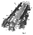
図1は、当該接着装置10内に本発明のローターブレード5の実施形態が収容されている、本発明の接着装置10の一実施形態の斜視図を示す。上記ローターブレード5は、3つの異なっているローターブレード部1、2、および3からなる。ここで、第1ローターブレード部1は前部シェル1として、第2ローターブレード部2は中間部セグメント2として、第3ローターブレード部3は後端セグメント3として形成されている。上記前部シェル1と上記中間部セグメント2との間にある接着領域21は、本質的に長手延長方向を向き、ローターブレードの吸引側にも正圧側にも形成されている。同様に、上記後端セグメント1と上記中間部セグメント2との間にある接着領域22は、本質的に長手延長方向を向き、ローターブレードの吸引側にも正圧側にも形成されている。上記前部シェル1も、上記中間部セグメント2も、それぞれ1つのベルト6により、それぞれ上記前部シェル1の内部、または、後端セグメント3の内部に固定されて、フランジ4に結合されている。上記フランジ4は、さらに、第4収容領域14に配置されている。フランジ4のこのような配置は、該フランジ4に備えられているいくつかのボルトの螺入により行われる。その螺合により、上記フランジ4は空間的に固定され、これにより、該フランジ4の移動は、意図しない、大きい機械的力で使用されたような場合でしか起こりえない。
FIG. 1 shows a perspective view of one embodiment of the
さらに、ローターブレード5は、示されている製造状態で開口部25を有し、該開口部25は、ローターブレード5の内部に出入りするのを保証することができる。上記開口部は、ローターブレード5の中にあるベルトあるいは棒をさらに加工するために必要である。加工完了後には、上記開口部25は、あらためては示さない部品で塞がれ、ここで、ローターブレード5の外皮は、フランジ4において全体的に取付けられている。上記開口部25の閉塞は、部品が、接着領域として形成されている境界において、接着剤により、上記中間部セグメント2と上記前部シェル1とに接着されることにより行われる。接着剤の加熱による硬化は、あらためては示さない装置により行われ得る。
Furthermore, the rotor blade 5 has an opening 25 in the production state shown, which can be guaranteed to enter and exit the rotor blade 5. The opening is necessary to further process the belt or rod in the rotor blade 5. After the processing is completed, the opening 25 is closed with parts not shown again, and the outer skin of the rotor blade 5 is attached to the flange 4 as a whole. The opening 25 is closed by adhering the component to the intermediate segment 2 and the
本実施形態による上記ローターブレード5を製造するために、最初に、接着装置10の第1収容領域11の内部に第1の予め製作されたローターブレード部1(前部シェル)が挿入されて固定されている。当該固定は、低圧による固定を可能にする、適切に備えられた吸引短管部により行われる。接着装置10の第3収容領域13の内部に、第3の予め製作されたローターブレード部1(前部シェル)も挿入されて固定されている。その固定は、同様に、低圧による固定により行われる。
In order to manufacture the rotor blade 5 according to the present embodiment, first, the first prefabricated rotor blade part 1 (front shell) is inserted into the first receiving area 11 of the
第1の予め製作されたローターブレード部1の挿入においても、第3の予め製作されたローターブレード部1の挿入においても、所定の位置、および、必要な精密さが、はめ込み時に保たれていることに注意が払われる。はめ込みを補助するために、上記収容部11および13が入れ子を有し、当該入れ子は、ローターブレード部1および3の外周の形状に適合し、したがって、ちょうど合う挿入が補助される。上記入れ子は、それぞれ第1支持構造物15および第3支持構造物17において取り付けられている。
In both the insertion of the first prefabricated
上記支持構造物15および17はそれぞれ、レール31における台の上に、地面に対して支持され、当該台の上に置いて互いに接近するように、または、互いから離れるように移動し得る。
Each of the
上記2つの支持構造物15および17の間のほぼ真ん中には1つのさらなる第2支持構造物16が配置され、当該第2支持構造物16の上に、同様に、あらためては示さない、または、見えない第2収容領域12が設けられている。当該第2支持構造物16は、中間部セグメント2として形成されている第2の予め製作されたローターブレード部2を収容するためのものであり、その中間部セグメント2は、示されているローターブレード5において、上記前部シェル1と上記後端セグメント3との間に配置されている。
A further second support structure 16 is arranged approximately in the middle between the two
次に、ローターブレード5を製造するために、上記第1支持構造物15およびその第1支持構造物15の内部に設けられている第1収容領域11の内部に収容されている第1ローターブレード部1(前部シェル)と、上記第3支持構造物17およびその第3支持構造物17の内部に設けられている第3収容領域13の内部に収容されている第3ローターブレード部3(後端セグメント)とが、相対的に接近して移動し、すなわち、上記2つの支持構造物15および17が、第2収容領域12の内部に収容されている第2ローターブレード部2へ移動する。上記第2収容領域12およびその第2収容領域12の内部に収容されている第2ローターブレード部2は、空間に関して、上記フランジ4と同様に、移動しないままである。上記移動は、上記前部シェル1の接着領域21、および、中間部セグメント2の接着領域21が十分互いに接触するまで行われる。ここで、中間に何も介在させない直接の接触が、上記接着領域21に付けられた接着剤で阻止されることもありうる。しかし、どんな場合でも、接着剤での接着を達成するために、上記2つの部品の接近は十分近い。
Next, in order to manufacture the rotor blade 5, the first rotor blade housed in the first support structure 15 and the first housing region 11 provided in the first support structure 15. Part 1 (front shell) and the third rotor blade part 3 (inside the
同様に、上記移動は、上記後端セグメント3と上記中間部セグメント2との接着領域22とが充分互いに接触するように行われる。ここで、中間に何も介在させない直接の接触が、また上記接着領域22に付けられた接着剤で阻止されることもありうる。しかし、どんな場合でも、接着剤での接着を達成するために、上記2つの部品の接近は十分近い。 Similarly, the movement is performed so that the rear end segment 3 and the bonding region 22 between the intermediate segment 2 are sufficiently in contact with each other. Here, the direct contact without interposing anything in between may also be prevented by the adhesive applied to the adhesive region 22. However, in any case, the two parts are close enough to achieve adhesive bonding.
上記第1支持構造物15および第3支持構造物17の移動は、同時に、または、時間的にずらして行われ得る。
The movement of the first support structure 15 and the
接着位置に到達すると、上記2つの接着領域21および22に沿って、第1収容領域11および第3収容領域13においてそれぞれ設けられた加熱装置40で熱エネルギーが局所的に加えられる。上記加熱装置40は、本質的に接着領域21および22のみに熱エネルギーが供給されるような配置および形状に形成されている。これにより、まだ硬化されていない接着剤が接着領域21および22において硬化し、したがって、第1ローターブレード部1(前部シェル)、第2ローターブレード部2(中間部セグメント)、および第3ローターブレード部3(後端セグメント)が互いに結合する。
When the adhesion position is reached, thermal energy is locally applied by the
同様に、上記フランジ4の結合が、第1ローターブレード部1(前部シェル)、第2ローターブレード部2(中間部セグメント)、および第3ローターブレード部3(後端セグメント)で行われ、ここで、接着剤の硬化は、あらためては関連記号が付けられていない接着領域において、ここでは、あらためては示さない加熱装置により行われる。 Similarly, the coupling of the flange 4 is performed in the first rotor blade portion 1 (front shell), the second rotor blade portion 2 (intermediate portion segment), and the third rotor blade portion 3 (rear end segment), Here, the curing of the adhesive is carried out in a bonding area, which is not given a related symbol, by a heating device which is not shown here again.
第1ローターブレード部1および第3ローターブレード部3の側におけるベルト末端6の結合は、本実施形態によれば、それぞれ傍らに配置されている押圧部50を用いて行われ、当該押圧部50は、同様に、レールの上をフランジ4の方向に移動することができる。十分な接近の後、あらかじめ形成された表面が、フランジに接着されている上記ベルト末端6を押圧し、したがって、当該ベルト末端6がフランジ4の所定の領域を押圧する。その領域で、加熱により硬化が行われる。その硬化のために、押圧領域の傍らまたは押圧領域内に加熱装置を設けることができる。
According to the present embodiment, the belt end 6 on the side of the first
上記押圧部50、第1支持構造物15および第3支持構造物17の移動は、ガイドされ、個々に行うことができる。
The movement of the
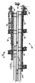
図2は、当該接着装置10内にローターブレードが収容されていない、図1による本発明の接着装置10の一実施形態の斜視側面図を示す。上記フランジ4の固定のために設けられている第4収容領域14が明確に示されている。ここで、フランジ4は、ボルト収容部18に収容されている、ボルト輪のいくつかのボルトで固定されている。本実施形態によれば、上記ボルト収容部18は、貫通穴18として形成され、当該貫通穴18を通ってボルトが貫通し、反対側においてねじで固定されている。
FIG. 2 shows a perspective side view of one embodiment of the
第2支持構造物16の上に備えられた第2収容領域12も明確に示されている(第2収容領域12および第2支持構造物16は、両方とも第4収容領域14の後ろに配置され、斜視的に描かれている)。 The second storage area 12 provided on the second support structure 16 is also clearly shown (both the second storage area 12 and the second support structure 16 are arranged behind the fourth storage area 14). And is drawn in perspective).
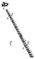
図3は、当該接着装置10内に、ローターブレード5が収容されていない、前記図面による本発明の接着装置10の実施例の平面断面図を示す。図面には、示されていない第1ローターブレード部1(前部シェル)を収容するための第1収容領域11を有する第1支持構造物15が明確に示されている。さらに、示されていない第3ローターブレード部3(後端セグメント)を収容するための第3収容領域13を有する上記第3支持構造物17が示されている。上記2つの支持構造物15および17は、第2支持構造物16の上に取り付けられている第2収容領域12の片側にそれぞれ配置されている。
FIG. 3 shows a cross-sectional plan view of an embodiment of the
さらに、第1支持構造物15の側にも、第3支持構造物17の側にも、互いに平行に配置されている一対のレール31が延び、当該一対のレール31は、それぞれ、接着剤装置30のためのものである(図5をも参照)。このような接着剤装置は、上記レール31に沿って移動可能であり、これにより、あらためては示さないローターブレード部1、2および3の全ての接着領域21および22に接着剤を供給して接着することができる。ここで、上記レール31は、第2収容領域12の長手延長に本質的に平行に延びる。
Further, a pair of rails 31 arranged in parallel to each other extend on the first support structure 15 side and on the
さらに、図3は、第1支持構造物15の側において、3対の平行に延びるレール31からなる一つの組を示す。当該3対のレール31は、第1支持構造物15が第2収容領域12の方向に移動するためのものである。さらに、第3支持構造物17の側において、4対の平行に延びるレール31からなる一つの組が配置されている。当該4対のレール31は、同様に、第3支持構造物17が第2収容領域12の方向に移動するためのものである。上記レールの対は、その延びる方向に関して、接着剤装置のために設けられているレール31に対して本質的に垂直に配置されている。
Further, FIG. 3 shows one set of three pairs of rails 31 extending in parallel on the first support structure 15 side. The three pairs of rails 31 are for the first support structure 15 to move in the direction of the second accommodation region 12. Further, on the
図4は、前記図面に示されている、接着装置10の実施形態に相当する、本発明のローターブレード5(示されていない)の実施形態の中間部セグメントを収容するための第2収容領域12の斜視図を示す。ここで、第2収容領域12は、2つの部分に分けられ、第2支持構造物16に支えられている。第2収容領域12の長手延長方向の端には、上記フランジ4を支持するための第4収容領域14が設けられている。
FIG. 4 shows a second receiving area for receiving the intermediate segment of an embodiment of the rotor blade 5 (not shown) according to the invention, corresponding to the embodiment of the
上記第2収容領域12は、その長手延長のほぼ真ん中において切断され、隙間を有する。当該隙間は、例えばここには示されていない調節具を設ければ、調節に有利になりうる。 The second accommodating region 12 is cut in the middle of its longitudinal extension and has a gap. The gap can be advantageous for adjustment, for example, if an adjustment tool not shown here is provided.
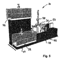
図5は、前記図面に示されている接着装置10のあらためては示さない実施形態の接着剤装置30の斜視図を示す。当該接着装置10は、それぞれ異なる平面で働き得る、複数の人(ここでは3人)を収容するのに適している。上記接着剤装置30は、その高さで(示されている位置に応じて)使用可能な2つの人用足場35を有する。上記人は、例えばホース(ここでは示されていない)が装備され、当該ホースは、接着剤(例えば通常のエポキシ接着剤)を付けるのに、および適用量を調整するのに適している。そのために、上記ホースは、さらに、接着剤を出す、適切な吹出口を有してもよい。
FIG. 5 shows a perspective view of an
上記ホースは、適切な制御部が設けられた取り出し部36において、別のホースの側に通じている。取り出し部36は、提供されている接着剤をホースに分配するポンプ(示されていない)と協働する。上記各ホースは、取り出し部36から、(取り付けられている位置に応じて)上方に延び、張力軽減のために、ホースホルダ38に固定されている。上記接着剤は、貯蔵容器37から取り出される。
The hose communicates with another hose side in the take-out
前方移動のために、上記接着剤装置30は、レールキャスター39を用いて、あらためては示さないレール31に対して支えられ、当該レール31の上に適した適切な駆動装置(示されていない)によって、当該レール31上を自律的に移動することができる。
For the forward movement, the
さらなる実施形態は、下位の請求項から明らかとなる。さらに、図面に示されている特徴の全てが、それ自体およびそれらの組み合わせとして、ここに特許請求されていることに注意すべきである。 Further embodiments will become apparent from the subclaims. Furthermore, it should be noted that all of the features shown in the drawings are claimed herein as such and combinations thereof.
1 第1ローターブレード部
2 第2ローターブレード部
3 第3ローターブレード部
4 フランジ
5 ローターブレード
6 ベルト末端
10 接着装置
11 第1収容領域
12 第2収容領域
13 第3収容領域
14 第4収容領域
15 第1支持構造物
16 第2支持構造物
17 第3支持構造物
18 ボルト収容部
21 接着領域
22 接着領域
25 開口部
30 接着剤装置
31 レール
35 人用足場
36 取り出し部
37 貯蔵容器
38 管留め具
39 レールキャスター
40 加熱装置
50 押圧部
60 吸引部
DESCRIPTION OF
Claims (16)
第1の予め製作されたローターブレード部(1)を収容する第1収容領域(11)と、第2の予め製作されたローターブレード部(2)を収容する第2収容領域(12)と、第3の予め製作されたローターブレード部(3)を収容する第3収容領域(13)と、を有し、第1収容領域(11)、第2収容領域(12)、第3収容領域(13)は、互いに相対的に移動可能であり、接着装置(10)の開位置にての適切な収容領域(11、12、13)における3つの予め製作されたローターブレード部(1、2、3)の収容の完了に続いて、ローターブレード部(1、2、3)が、所定の接着領域(21、22)を介して互いに直接または間接に接触させられて、接着位置に移されることができ、
第1収容領域(11)と第3収容領域(13)とは、互いに向かって接近するように移動可能であり、第2収容領域(12)は、空間内で移動しないままであり、第2収容領域(12)は第1収容領域(11)と第3収容領域(13)との間に位置している、接着装置。 A bonding device (10) for building a segmented rotor blade (5) comprising at least three prefabricated rotor blade sections (1, 2, 3), comprising:
A first receiving area (11) for receiving a first pre-made rotor blade part (1), a second receiving area (12) for containing a second pre-made rotor blade part (2); A third storage region (13) for storing a third pre-manufactured rotor blade part (3), and a first storage region (11), a second storage region (12), a third storage region ( 13) is movable relative to each other and is provided with three prefabricated rotor blade portions (1, 2, 13) in a suitable receiving area (11, 12, 13) in the open position of the bonding device (10). Following the completion of the accommodation in 3), the rotor blade portions (1, 2, 3) are brought into contact with each other directly or indirectly via the predetermined bonding area (21, 22) and moved to the bonding position. Can
The first storage area (11) and the third storage area (13) are movable so as to approach each other, and the second storage area (12) remains stationary in the space, The accommodation device (12) is located between the first accommodation region (11) and the third accommodation region (13).
接着装置(10)の3つ全てのローターブレード部(1、2、3)が、収容され、かつ、所定の収容領域(11、12、13)を介して他のローターブレード部(1、2、3)と直接または間接に接触して、接着のために接着位置に移されるように、ローターブレード部(1、2、3)が接着装置(10)の支援で接着され、第1収容領域(11)および該第1収容領域(11)内に収容された第1ローターブレード部(1)と、第3収容領域(13)および該第3収容領域(13)内に収容された第3ローターブレード部(3)とが、相対的に接近して移動され、第1収容領域と第3収容領域との間に位置する第2収容領域(12)および該第2収容領域(12)内に収容された第2ローターブレード部(2)は移動しないままであることを特徴とする、方法。 A method for bonding at least three pre-fabricated rotor blade sections for the construction of segmented rotor blades, comprising:
All three rotor blade portions (1, 2, 3) of the bonding apparatus (10) are accommodated, and the other rotor blade portions (1, 2, 13) via a predetermined accommodating area (11, 12, 13). 3) the rotor blade parts (1, 2, 3) are bonded with the aid of the bonding device (10) so that they are brought into direct or indirect contact with each other and transferred to the bonding position for bonding. (11) and the first rotor blade portion (1) housed in the first housing area (11), the third housing area (13) and the third housed in the third housing area (13). The rotor blade portion (3) is moved relatively close to the second storage area (12) located between the first storage area and the third storage area, and the second storage area (12). The second rotor blade part (2) housed in the cylinder remains stationary And wherein, method.
Applications Claiming Priority (3)
| Application Number | Priority Date | Filing Date | Title |
|---|---|---|---|
| DE102011078804A DE102011078804A1 (en) | 2011-07-07 | 2011-07-07 | Gluing device for the construction of segmented rotor blades |
| DE102011078804.2 | 2011-07-07 | ||
| PCT/EP2012/060667 WO2013004445A1 (en) | 2011-07-07 | 2012-06-06 | Adhesive device for constructing segmented rotor blades |
Publications (3)
| Publication Number | Publication Date |
|---|---|
| JP2014520994A JP2014520994A (en) | 2014-08-25 |
| JP2014520994A5 JP2014520994A5 (en) | 2015-04-02 |
| JP5908074B2 true JP5908074B2 (en) | 2016-04-26 |
Family
ID=46229489
Family Applications (1)
| Application Number | Title | Priority Date | Filing Date |
|---|---|---|---|
| JP2014517558A Active JP5908074B2 (en) | 2011-07-07 | 2012-06-06 | Adhesive equipment for the construction of segmented rotor blades |
Country Status (7)
| Country | Link |
|---|---|
| US (1) | US9689371B2 (en) |
| EP (1) | EP2729295B1 (en) |
| JP (1) | JP5908074B2 (en) |
| CN (1) | CN103648752B (en) |
| AU (1) | AU2012280585B2 (en) |
| DE (1) | DE102011078804A1 (en) |
| WO (1) | WO2013004445A1 (en) |
Families Citing this family (7)
| Publication number | Priority date | Publication date | Assignee | Title |
|---|---|---|---|---|
| US10118352B2 (en) * | 2013-05-31 | 2018-11-06 | LM WP Patent Holdings A/S | System and method for assisting in the manufacture of a wind turbine blade shell |
| CN103331236B (en) * | 2013-07-10 | 2015-07-15 | 洛阳双瑞风电叶片有限公司 | Aerogenerator blade tail edge gluing tool and making method thereof |
| DE102014206751A1 (en) * | 2014-04-08 | 2015-10-08 | Bayerische Motoren Werke Aktiengesellschaft | Method and production system for laminating interior components of vehicles |
| CN110267800B (en) | 2017-01-12 | 2021-01-12 | 维斯塔斯风力系统有限公司 | Method and apparatus for assembling a wind turbine blade with an internal web |
| WO2019241371A1 (en) | 2018-06-12 | 2019-12-19 | Tpi Composites, Inc. | Wind blade component bonding fixture |
| DE102018128863A1 (en) * | 2018-11-16 | 2020-05-20 | HELLA GmbH & Co. KGaA | Method for gluing two components that are positioned exactly in relation to each other |
| CN117507380B (en) * | 2023-12-07 | 2024-06-14 | 新创碳谷集团有限公司 | Modularized blade girder bonding device and method |
Family Cites Families (6)
| Publication number | Priority date | Publication date | Assignee | Title |
|---|---|---|---|---|
| DE102004021389A1 (en) | 2004-04-30 | 2005-11-24 | Daimlerchrysler Ag | Method and device for connecting at least two workpieces |
| ES2342638B1 (en) * | 2007-02-28 | 2011-05-13 | GAMESA INNOVATION & TECHNOLOGY, S.L. | A MULTI-PANEL AIRPLANE SHOVEL. |
| EP2283230B1 (en) * | 2008-03-05 | 2012-05-16 | Vestas Wind Systems A/S | An assembly tool and a method of manufacturing a blade of a wind turbine |
| GB0807515D0 (en) * | 2008-04-24 | 2008-06-04 | Blade Dynamics Ltd | A wind turbine blade |
| DE102008038620A1 (en) * | 2008-06-27 | 2009-12-31 | Powerblades Gmbh | Method and manufacturing method for manufacturing a rotor blade for a wind energy plant |
| DE102009033164A1 (en) * | 2009-07-13 | 2011-01-27 | Repower Systems Ag | Rotor blade of a wind energy plant and method for manufacturing a rotor blade of a wind turbine |
-
2011
- 2011-07-07 DE DE102011078804A patent/DE102011078804A1/en not_active Ceased
-
2012
- 2012-06-06 AU AU2012280585A patent/AU2012280585B2/en not_active Ceased
- 2012-06-06 JP JP2014517558A patent/JP5908074B2/en active Active
- 2012-06-06 EP EP12726426.5A patent/EP2729295B1/en active Active
- 2012-06-06 CN CN201280033836.0A patent/CN103648752B/en not_active Expired - Fee Related
- 2012-06-06 WO PCT/EP2012/060667 patent/WO2013004445A1/en active Application Filing
-
2014
- 2014-01-07 US US14/148,934 patent/US9689371B2/en not_active Expired - Fee Related
Also Published As
| Publication number | Publication date |
|---|---|
| CN103648752B (en) | 2016-12-21 |
| US20140119935A1 (en) | 2014-05-01 |
| AU2012280585A1 (en) | 2013-05-02 |
| AU2012280585B2 (en) | 2015-03-12 |
| JP2014520994A (en) | 2014-08-25 |
| US9689371B2 (en) | 2017-06-27 |
| WO2013004445A1 (en) | 2013-01-10 |
| EP2729295A1 (en) | 2014-05-14 |
| DE102011078804A1 (en) | 2013-01-10 |
| CN103648752A (en) | 2014-03-19 |
| EP2729295B1 (en) | 2019-08-07 |
Similar Documents
| Publication | Publication Date | Title |
|---|---|---|
| JP5908074B2 (en) | Adhesive equipment for the construction of segmented rotor blades | |
| JP2014520994A5 (en) | ||
| US8425195B2 (en) | Wind turbine blade | |
| US11691352B2 (en) | Post-modulation station and an associated method of manufacture of a wind turbine blade | |
| KR101834981B1 (en) | Module for holding at least one bushing | |
| US9133818B2 (en) | Wind turbine blade | |
| US10843303B2 (en) | System and method for manufacturing a wind turbine blade | |
| EP2809500B1 (en) | A cradle for a wind turbine blade | |
| CN105899351A (en) | Wind turbine blades | |
| CN105431281A (en) | System and method for assisting in the manufacture of a wind turbine blade shell | |
| CN105073400A (en) | Method of manufacturing a wind turbine blade using pre-fabricated stacks of reinforcing material | |
| EP3019332B1 (en) | Wind turbine blade | |
| EP3802090A1 (en) | A system and method for manufacturing a wind turbine blade | |
| CN211549890U (en) | Wind turbine blade root modular prefabricated part, blade root part and blade | |
| JP7198920B2 (en) | Bonding jig for wind blade components | |
| EP3706987B1 (en) | Improvements relating to wind turbine blade manufacture | |
| DK201570772A1 (en) | Tool and method for fabricating shear webs for a wind turbine blade |
Legal Events
| Date | Code | Title | Description |
|---|---|---|---|
| A131 | Notification of reasons for refusal |
Free format text: JAPANESE INTERMEDIATE CODE: A131 Effective date: 20140901 |
|
| A601 | Written request for extension of time |
Free format text: JAPANESE INTERMEDIATE CODE: A601 Effective date: 20141128 |
|
| A602 | Written permission of extension of time |
Free format text: JAPANESE INTERMEDIATE CODE: A602 Effective date: 20141205 |
|
| A601 | Written request for extension of time |
Free format text: JAPANESE INTERMEDIATE CODE: A601 Effective date: 20141225 |
|
| A601 | Written request for extension of time |
Free format text: JAPANESE INTERMEDIATE CODE: A601 Effective date: 20150202 |
|
| A524 | Written submission of copy of amendment under article 19 pct |
Free format text: JAPANESE INTERMEDIATE CODE: A524 Effective date: 20150210 |
|
| A711 | Notification of change in applicant |
Free format text: JAPANESE INTERMEDIATE CODE: A711 Effective date: 20150223 |
|
| A521 | Request for written amendment filed |
Free format text: JAPANESE INTERMEDIATE CODE: A821 Effective date: 20150223 |
|
| A131 | Notification of reasons for refusal |
Free format text: JAPANESE INTERMEDIATE CODE: A131 Effective date: 20150810 |
|
| A521 | Request for written amendment filed |
Free format text: JAPANESE INTERMEDIATE CODE: A523 Effective date: 20151029 |
|
| TRDD | Decision of grant or rejection written | ||
| A01 | Written decision to grant a patent or to grant a registration (utility model) |
Free format text: JAPANESE INTERMEDIATE CODE: A01 Effective date: 20160222 |
|
| A61 | First payment of annual fees (during grant procedure) |
Free format text: JAPANESE INTERMEDIATE CODE: A61 Effective date: 20160322 |
|
| R150 | Certificate of patent or registration of utility model |
Ref document number: 5908074 Country of ref document: JP Free format text: JAPANESE INTERMEDIATE CODE: R150 |
|
| R250 | Receipt of annual fees |
Free format text: JAPANESE INTERMEDIATE CODE: R250 |