EP2728201B1 - Elektropneumatisches Stellgerät und elektropneumatische Baugruppe - Google Patents
Elektropneumatisches Stellgerät und elektropneumatische Baugruppe Download PDFInfo
- Publication number
- EP2728201B1 EP2728201B1 EP13004694.9A EP13004694A EP2728201B1 EP 2728201 B1 EP2728201 B1 EP 2728201B1 EP 13004694 A EP13004694 A EP 13004694A EP 2728201 B1 EP2728201 B1 EP 2728201B1
- Authority
- EP
- European Patent Office
- Prior art keywords
- pneumatic
- slot
- electropneumatic
- electronic
- field device
- Prior art date
- Legal status (The legal status is an assumption and is not a legal conclusion. Google has not performed a legal analysis and makes no representation as to the accuracy of the status listed.)
- Active
Links
- 230000005684 electric field Effects 0.000 claims description 16
- 230000015654 memory Effects 0.000 claims description 10
- 230000006870 function Effects 0.000 claims description 9
- 230000007246 mechanism Effects 0.000 claims description 9
- 238000003032 molecular docking Methods 0.000 claims description 8
- 230000008878 coupling Effects 0.000 claims description 4
- 238000010168 coupling process Methods 0.000 claims description 4
- 238000005859 coupling reaction Methods 0.000 claims description 4
- 238000005192 partition Methods 0.000 claims description 2
- 238000012545 processing Methods 0.000 claims description 2
- 238000010586 diagram Methods 0.000 claims 5
- 230000013011 mating Effects 0.000 claims 2
- 238000000034 method Methods 0.000 description 10
- 230000008569 process Effects 0.000 description 10
- 238000013461 design Methods 0.000 description 8
- 238000013022 venting Methods 0.000 description 7
- 230000001276 controlling effect Effects 0.000 description 5
- 238000011161 development Methods 0.000 description 5
- 230000018109 developmental process Effects 0.000 description 5
- 230000008859 change Effects 0.000 description 3
- 238000013500 data storage Methods 0.000 description 3
- 239000012530 fluid Substances 0.000 description 3
- 238000012423 maintenance Methods 0.000 description 3
- 230000008901 benefit Effects 0.000 description 2
- 238000004891 communication Methods 0.000 description 2
- 230000000295 complement effect Effects 0.000 description 2
- 238000010327 methods by industry Methods 0.000 description 2
- 230000001105 regulatory effect Effects 0.000 description 2
- 230000008054 signal transmission Effects 0.000 description 2
- 230000009471 action Effects 0.000 description 1
- 230000004913 activation Effects 0.000 description 1
- 238000006243 chemical reaction Methods 0.000 description 1
- 238000010248 power generation Methods 0.000 description 1
- 230000036316 preload Effects 0.000 description 1
Images


Classifications
-
- F—MECHANICAL ENGINEERING; LIGHTING; HEATING; WEAPONS; BLASTING
- F15—FLUID-PRESSURE ACTUATORS; HYDRAULICS OR PNEUMATICS IN GENERAL
- F15B—SYSTEMS ACTING BY MEANS OF FLUIDS IN GENERAL; FLUID-PRESSURE ACTUATORS, e.g. SERVOMOTORS; DETAILS OF FLUID-PRESSURE SYSTEMS, NOT OTHERWISE PROVIDED FOR
- F15B21/00—Common features of fluid actuator systems; Fluid-pressure actuator systems or details thereof, not covered by any other group of this subclass
- F15B21/08—Servomotor systems incorporating electrically operated control means
-
- F—MECHANICAL ENGINEERING; LIGHTING; HEATING; WEAPONS; BLASTING
- F15—FLUID-PRESSURE ACTUATORS; HYDRAULICS OR PNEUMATICS IN GENERAL
- F15B—SYSTEMS ACTING BY MEANS OF FLUIDS IN GENERAL; FLUID-PRESSURE ACTUATORS, e.g. SERVOMOTORS; DETAILS OF FLUID-PRESSURE SYSTEMS, NOT OTHERWISE PROVIDED FOR
- F15B5/00—Transducers converting variations of physical quantities, e.g. expressed by variations in positions of members, into fluid-pressure variations or vice versa; Varying fluid pressure as a function of variations of a plurality of fluid pressures or variations of other quantities
- F15B5/006—Transducers converting variations of physical quantities, e.g. expressed by variations in positions of members, into fluid-pressure variations or vice versa; Varying fluid pressure as a function of variations of a plurality of fluid pressures or variations of other quantities with electrical means, e.g. electropneumatic transducer
-
- F—MECHANICAL ENGINEERING; LIGHTING; HEATING; WEAPONS; BLASTING
- F15—FLUID-PRESSURE ACTUATORS; HYDRAULICS OR PNEUMATICS IN GENERAL
- F15B—SYSTEMS ACTING BY MEANS OF FLUIDS IN GENERAL; FLUID-PRESSURE ACTUATORS, e.g. SERVOMOTORS; DETAILS OF FLUID-PRESSURE SYSTEMS, NOT OTHERWISE PROVIDED FOR
- F15B15/00—Fluid-actuated devices for displacing a member from one position to another; Gearing associated therewith
- F15B15/20—Other details, e.g. assembly with regulating devices
- F15B15/202—Externally-operated valves mounted in or on the actuator
-
- F—MECHANICAL ENGINEERING; LIGHTING; HEATING; WEAPONS; BLASTING
- F15—FLUID-PRESSURE ACTUATORS; HYDRAULICS OR PNEUMATICS IN GENERAL
- F15B—SYSTEMS ACTING BY MEANS OF FLUIDS IN GENERAL; FLUID-PRESSURE ACTUATORS, e.g. SERVOMOTORS; DETAILS OF FLUID-PRESSURE SYSTEMS, NOT OTHERWISE PROVIDED FOR
- F15B13/00—Details of servomotor systems ; Valves for servomotor systems
- F15B13/02—Fluid distribution or supply devices characterised by their adaptation to the control of servomotors
- F15B13/04—Fluid distribution or supply devices characterised by their adaptation to the control of servomotors for use with a single servomotor
- F15B13/042—Fluid distribution or supply devices characterised by their adaptation to the control of servomotors for use with a single servomotor operated by fluid pressure
- F15B13/043—Fluid distribution or supply devices characterised by their adaptation to the control of servomotors for use with a single servomotor operated by fluid pressure with electrically-controlled pilot valves
-
- F—MECHANICAL ENGINEERING; LIGHTING; HEATING; WEAPONS; BLASTING
- F15—FLUID-PRESSURE ACTUATORS; HYDRAULICS OR PNEUMATICS IN GENERAL
- F15B—SYSTEMS ACTING BY MEANS OF FLUIDS IN GENERAL; FLUID-PRESSURE ACTUATORS, e.g. SERVOMOTORS; DETAILS OF FLUID-PRESSURE SYSTEMS, NOT OTHERWISE PROVIDED FOR
- F15B13/00—Details of servomotor systems ; Valves for servomotor systems
- F15B2013/002—Modular valves, i.e. consisting of an assembly of interchangeable components
- F15B2013/006—Modular components with multiple uses, e.g. kits for either normally-open or normally-closed valves, interchangeable or reprogrammable manifolds
-
- F—MECHANICAL ENGINEERING; LIGHTING; HEATING; WEAPONS; BLASTING
- F15—FLUID-PRESSURE ACTUATORS; HYDRAULICS OR PNEUMATICS IN GENERAL
- F15B—SYSTEMS ACTING BY MEANS OF FLUIDS IN GENERAL; FLUID-PRESSURE ACTUATORS, e.g. SERVOMOTORS; DETAILS OF FLUID-PRESSURE SYSTEMS, NOT OTHERWISE PROVIDED FOR
- F15B2211/00—Circuits for servomotor systems
- F15B2211/30—Directional control
- F15B2211/305—Directional control characterised by the type of valves
- F15B2211/3056—Assemblies of multiple valves
- F15B2211/30565—Assemblies of multiple valves having multiple valves for a single output member, e.g. for creating higher valve function by use of multiple valves like two 2/2-valves replacing a 5/3-valve
-
- F—MECHANICAL ENGINEERING; LIGHTING; HEATING; WEAPONS; BLASTING
- F15—FLUID-PRESSURE ACTUATORS; HYDRAULICS OR PNEUMATICS IN GENERAL
- F15B—SYSTEMS ACTING BY MEANS OF FLUIDS IN GENERAL; FLUID-PRESSURE ACTUATORS, e.g. SERVOMOTORS; DETAILS OF FLUID-PRESSURE SYSTEMS, NOT OTHERWISE PROVIDED FOR
- F15B2211/00—Circuits for servomotor systems
- F15B2211/60—Circuit components or control therefor
- F15B2211/63—Electronic controllers
- F15B2211/6303—Electronic controllers using input signals
- F15B2211/6336—Electronic controllers using input signals representing a state of the output member, e.g. position, speed or acceleration
-
- F—MECHANICAL ENGINEERING; LIGHTING; HEATING; WEAPONS; BLASTING
- F15—FLUID-PRESSURE ACTUATORS; HYDRAULICS OR PNEUMATICS IN GENERAL
- F15B—SYSTEMS ACTING BY MEANS OF FLUIDS IN GENERAL; FLUID-PRESSURE ACTUATORS, e.g. SERVOMOTORS; DETAILS OF FLUID-PRESSURE SYSTEMS, NOT OTHERWISE PROVIDED FOR
- F15B2211/00—Circuits for servomotor systems
- F15B2211/60—Circuit components or control therefor
- F15B2211/665—Methods of control using electronic components
- F15B2211/6653—Pressure control
-
- F—MECHANICAL ENGINEERING; LIGHTING; HEATING; WEAPONS; BLASTING
- F15—FLUID-PRESSURE ACTUATORS; HYDRAULICS OR PNEUMATICS IN GENERAL
- F15B—SYSTEMS ACTING BY MEANS OF FLUIDS IN GENERAL; FLUID-PRESSURE ACTUATORS, e.g. SERVOMOTORS; DETAILS OF FLUID-PRESSURE SYSTEMS, NOT OTHERWISE PROVIDED FOR
- F15B2211/00—Circuits for servomotor systems
- F15B2211/60—Circuit components or control therefor
- F15B2211/665—Methods of control using electronic components
- F15B2211/6656—Closed loop control, i.e. control using feedback
-
- F—MECHANICAL ENGINEERING; LIGHTING; HEATING; WEAPONS; BLASTING
- F15—FLUID-PRESSURE ACTUATORS; HYDRAULICS OR PNEUMATICS IN GENERAL
- F15B—SYSTEMS ACTING BY MEANS OF FLUIDS IN GENERAL; FLUID-PRESSURE ACTUATORS, e.g. SERVOMOTORS; DETAILS OF FLUID-PRESSURE SYSTEMS, NOT OTHERWISE PROVIDED FOR
- F15B2211/00—Circuits for servomotor systems
- F15B2211/80—Other types of control related to particular problems or conditions
- F15B2211/885—Control specific to the type of fluid, e.g. specific to magnetorheological fluid
- F15B2211/8855—Compressible fluids, e.g. specific to pneumatics
Definitions
- the invention relates to an electropneumatic field device, such as an electropneumatic positioner, an I/P converter or the like.
- the electropneumatic field device is often used as a control device for controlling a pneumatic actuator of a process plant, for example in the petrochemical industry, the food industry or the like, which in turn actuates a control valve for regulating a flow of process fluid.
- the electro-pneumatic field device has at least one electric field input, via which the field device receives an electric field input signal, which can be formed as a setpoint control signal, for example in the case of a pneumatically operated control valve.
- the field input signal can be, for example, an analog 4-20mA current signal or a digital fieldbus signal such as Profibus PA, Foundation Fieldbus, ASI or Devicenet.
- the electropneumatic field device has at least one electronic and/or pneumatic component, which can be, for example, an electropneumatic converter, a data memory, a pneumatic current generator and/or a microprocessor.
- the electropneumatic field device may include multiple electronic and/or pneumatic components, such as multiple electropneumatic converters, microprocessors, electrical switches, data storage, and/or pneumatic power generators.
- the at least one electronic and/or pneumatic component is connected to the at least one electric field input to receive the electric field input signal. It is known, particularly in the case of a positioner as a field device, that control and/or regulation electronics can be connected between the electrical field input and the electronic and/or pneumatic component.
- the electropneumatic converter is pneumatically coupled to the pneumatic supply input of the field device.
- the field device usually has a pneumatic field output, at which a pneumatic field output signal, for example for controlling the pneumatic actuator, can be output based on the received field input signal.
- EP 2 258 952 A2 relates to a piezo-pneumatic valve unit and a pneumatic positioner with a pneumatic working element and a piezo-pneumatic valve unit acting on this.
- EP 1 632 679 A1 relates to an electropneumatic positioner with a valve for dividing compressed air between two exhaust air connections for an actuator that can be connected to it.
- EP 1 515 050 A2 discloses a control unit with a base on which at least one assembly location is provided, which is equipped with a first electrical central interface connected to an internal electrical bus running in the base, and with at least one electrical connection module that allows for detachable connection of electrical cables leading away from the control unit enabling electrical inputs and/or outputs and which can be detachably mounted on the at least one assembly location, wherein it has a second electrical central interface that automatically makes contact or separates with respect to the first electrical central interface during assembly and disassembly of the electrical connection module.
- DE 10316129 A1 discloses a diagnostic module and a controller for a valve battery.
- an electropneumatic field device in which several electronic and/or pneumatic components, such as an electronic controller, a U/I converter, an I/P converter, a power amplifier and an inverting amplifier, can be used.
- a reversing amplifier is used when the electropneumatic field device accesses a double-acting pneumatic actuator.
- a positioner for controlling and/or regulating a pneumatic actuator has a main body and a removable maintenance cassette, the interior of which is divided into a compartment for electro-pneumatic components and an electronics compartment.
- the entire maintenance cartridge is detachable from the main body for maintenance purposes.
- the electropneumatic field device such as the electropneumatic positioner, the I/P converter or the like, has at least one electrical field input, one pneumatic supply input, at least one electronic and/or pneumatic component, such as an electropneumatic converter, preferably several electropneumatic converters, a Microprocessor, a data memory, a pneumatic power generator and/or the like.
- the at least one electronic and/or pneumatic component is connected to the at least one electrical field input and optionally to the pneumatic supply input.
- the pneumatic field device has a field output at which a field output signal can be emitted using a field signal, in particular an actuating and/or control signal, received via the at least one electric field input.
- the electropneumatic field device has a group consisting of at least two modular electronic and/or pneumatic components with different functionality and at least one modular slot for occupation with one electronic and/or pneumatic component each.
- the at least two electronic and/or pneumatic components of the group and the at least one slot are modularly matched to one another in such a way that their electrical and optionally pneumatic interfaces are functionally and reliably transferred to one another when the slot is occupied.
- the electropneumatic field device can also have electronic and/or pneumatic components that are not arranged in a modular slot.
- a modular slot is used to accommodate a singular modular electronic and/or pneumatic component.
- the modular slot should be easily accessible from an outside of the field device. Those electronic and/or pneumatic components of the group that are not used can be stored on the outside of the housing in storage locations that are complementary in shape to the modular slot, in particular electrically blind, for later use in a modular slot.
- the field output of the electropneumatic field device can be both pneumatic and electrical and is preferably formed by one of the electronic and/or pneumatic components in the modular slot.
- an electropneumatic converter can be provided externally, ie outside the field device housing, which generates a pneumatic signal for delivery to the pneumatic actuator, for example, on the basis of the electric field output signal.
- the modular slot is designed to a single modular electronic and / or pneumatic component from the group of electronic and / or pneumatic components of different functionality, such as one or more electropneumatic converters, one or more microprocessors, one or more data storage, one or more pneumatic Power generators and/or the like, to be interchangeably accommodated by making an electrical connection at the respective electrical interfaces and, if necessary, by making a pneumatic connection between the respective pneumatic interfaces. Since the at least two electronic and/or pneumatic components are provided on the electropneumatic field device according to the invention so that they can be exchanged, the at least one slot is designed to be easily accessible from the outside (with respect to the field device housing).
- the electro-pneumatic field device has a high degree of modularity, which a plant operator or plant builder can use in order to adjust to changing process conditions in the plant without great assembly effort.
- Known positioners suffer from the disadvantage that permanently implemented I/P converters the air output of the field device is fixed, in particular limited, so that it cannot be changed.
- the measure according to the invention of creating modularity in particular with regard to all electronic and/or pneumatic components, such as the electropneumatic converter, the data memory, the pneumatic power generator, the microprocessor and/or the like, makes it possible, for example, to significantly increase the air output of the field device to increase or reduce, but also to change the control routine by exchanging the control microprocessor, to provide self-sufficient power generation and/or to change it by exchanging the pneumatic power generator, to use data for uploading and saving by exchanging data memories as desired, without the field device and/or its having to manipulate the environment.
- the system builder with the electropneumatic field device according to the invention does not require a great deal of time and design effort, let alone an interruption in the operation of the process engineering system if he wishes to change the operation of the electropneumatic field device in one or more functionalities.
- the electropneumatic field device according to the invention has the advantage of not necessarily having to use a separate volume booster (booster) in the pneumatic line system if the air line of the installed electropneumatic converter is no longer sufficient.
- the electropneumatic field device has at least two modular slots, both of which are occupied by a different electropneumatic converter.
- An electronic control system which is mounted permanently and non-replaceably within a housing of the electropneumatic field device, for example, but can also be exchanged for other position electronics by means of the modular slot, selects one of the two pressure converters depending on the operating conditions in order to ensure the functional operation of the electropneumatic field device to be able to use the most suitable pressure transducer parameters. In the meantime, the unselected electro-pneumatic converter remains in the slot in a passive waiting position.
- a third electro-pneumatic functionality is to be used in a two- or more-place field device, it is possible to exchange one of the electro-pneumatic converters occupying the slot for a third electro-pneumatic converter with the desired function, for example in a blind storage location on the outside of the field device housing was stored.
- All electronic and/or pneumatic components of the group that are available to be used in the at least one modular slot are, for example, modularly matched to the slot in that the slot has a female recess shape that is at least partially complementary in shape to the male outer profile of the respective electronic and/or pneumatic component.
- the coordinated forms are selected in such a way that only one plug-in position is permitted in order to ensure that the electrical interface and, if necessary, the pneumatic interface are adapted.
- the at least one slot has a docking mechanism that has a positive and/or non-positive locking device, such as a latching device, in particular a manually operable clamp or a screw connection for releasably fastening the respective electronic and/or pneumatic component in the modular slot includes.
- the positive and/or non-positive locking device can preferably be designed to communicate a preload to the respective electronic and/or pneumatic component, so that the respective electrical interfaces and, if applicable, the pneumatic interfaces of the slot and the electronic and/or pneumatic component are pressed against one another, to establish the electrical contact and, if necessary, the pneumatic connection.
- the at least one slot is realized by a depression or recess, in particular in a housing wall of the field device.
- the electrical component can be accommodated in a form-fitting manner in the depression.
- the electropneumatic field device has a number of modular slots.
- the multiple modular slots can either be occupied by the same electronic and/or pneumatic components, in particular with different functionality, or different electronic and/or pneumatic components. The assignment depends on the desired characteristics of the field device, for example the air capacity.
- the at least one slot has an electrical interface connected to the electrical field input and a pneumatic interface connected to the pneumatic supply input of the field device for pneumatically coupling a pneumatic connection of the electronic and/or pneumatic component if, for example, an I/P converter is to be used as the electronic and/or pneumatic component.
- the at least one slot has a closure assigned to the pneumatic interface, which seals the pneumatic interface of the at least one slot in an essentially airtight manner when it is unoccupied and if it is occupied by an electrical and/or pneumatic component without a pneumatic function.
- the closure is deactivated, so that a pneumatic connection of the pneumatic supply from the electropneumatic converter is established.
- each modular slot has an electrical interface connected to the at least one electrical field input and optionally a pneumatic interface coupled to the pneumatic supply input.
- the respective interface In the docked state of the respective electronic and/or pneumatic component, the respective interface is functionally connected to its electrical and optionally pneumatic connection.
- the at least one modular slot has a modular docking mechanism for the at least one modular electronic and/or pneumatic component.
- the docking mechanism is designed to firmly accommodate and hold the respective electronic and/or pneumatic component in the modular slot, in particular by means of a snap-in mechanism, and, if necessary, to exchange the electronic and/or pneumatic components, in particular non-destructively and preferably manually, in particular without special tools solve.
- the at least modular slot has an identification device for detecting the type/design of the electronic and/or pneumatic component.
- the identification device is preferably designed to close the airtight seal of the pneumatic interface of the slot if the slot is occupied by an electronic and/or pneumatic component without a pneumatic function, such as a microprocessor activate.
- the identification device can have an electrical and/or mechanical sensor, which may have an electronic unit, such as a permanently installed microprocessor, in particular, is functionally coupled to a pneumatic closure arranged on the slot.
- the field device has an electronic unit, such as a microprocessor, which can be used as a modular electronic and/or pneumatic component in the at least one modular slot.
- the electronics unit can also be permanently installed as a permanently installed, non-modular member within the field device housing.
- the electronic unit is designed to recognize the occupancy of the at least one modular slot with different electronic and/or pneumatic components and to correspondingly assign the field input signal received at the field device to the respective electronic and/or pneumatic component.
- the electropneumatic field device has a housing that can be closed, in particular in a fluid-tight manner.
- the housing can accommodate controller electronics that are in particular permanently installed.
- the at least one modular slot is set up on an outer wall of a partition wall of a compartment or on an outer wall of the housing, so that an operator thereby has manual access to the at least one slot.
- the arrangement can have a plurality of modular slots or just one modular slot by means of a housing part that can be removed from the housing, such as a cover, which can be closed preferably in a fluid-tight manner, in particular to form a second housing part.
- the at least one modular slot has an electrical connection pattern and optionally a pneumatic connection pattern.
- the at least one electronic and/or pneumatic component can have an electrical counter-connection pattern and optionally a pneumatic counter-connection pattern, with the counter-connection pattern being a mirror image of the connection pattern, so that when the electronic and/or pneumatic component is simply inserted into the slot, the electrical contact and optionally the pneumatic connection is established.
- the electropneumatic field device has at least one pair of modular slots, preferably three pairs of modular slots, all slots being occupied by an electropneumatic converter and in particular one electro-pneumatic converter of the pair of slots can be connected directly to a pneumatic working chamber of a control valve and the other electro-pneumatic converter of the pair of slots can be pneumatically coupled to a pneumatic actuator, such as an air vent or a quick-release air vent, with the quick-release air vent being connected to the pneumatic working chamber in such a way that upon receipt an in particular predetermined pneumatic output signal of the other electropneumatic converter of the pair of slots, the pneumatic working chamber of the actuator can be vented, preferably coupled to an atmospheric pressure outlet of the pneumatic actuator, wherein in the case of a double-acting pneumatic actuator, the second working chamber can be controlled by a second pair of correspondingly occupied slots .
- a pneumatic actuator such as an air vent or a quick-release air vent
- the electropneumatic field device has a pair of modular slots, one slot being occupied by an electropneumatic converter and the other slot being occupied by an electrical output stage, the electropneumatic converter being connected to an external electropneumatic converter, in particular arranged outside a housing of the field device Converter, such as a solenoid valve, is connected, which is connected to a working chamber of an actuator, the electrical output stage being connected to the external electro-pneumatic converter in such a way that when a predetermined electrical signal is emitted, the external electro-pneumatic converter is vented, wherein in the case of a double acting, pneumatic actuator, a second pair of correspondingly occupied slots is provided for controlling the second working chamber.
- an external electropneumatic converter in particular arranged outside a housing of the field device Converter, such as a solenoid valve, is connected, which is connected to a working chamber of an actuator, the electrical output stage being connected to the external electro-pneumatic converter in such a way that when a predetermined electrical signal is emitted
- the electropneumatic field device has a group of at least two modular electronic and/or pneumatic components, at least one electropneumatic converter, at least one pneumatic current generator, at least one microprocessor, at least one electrical output stage, such as at least one switch, and/or at least a data store.
- the housing structure for the electropneumatic field device is not realized from a common housing for all components, but the housing of the electropneumatic field device is divided into at least two separate housing parts.
- the electronic and/or pneumatic components are to be arranged in respective slots in a first housing part, with the slots preferably being accessible from the outside.
- second housing in particular, only the slots for pneumatic components are provided.
- the housing for the electronic and/or pneumatic components can be realized on a yoke or lantern connecting the actuator to the control valve housing, with the electronic and/or pneumatic components being a microcomputer, a position sensor or the like, for example.
- the second housing for the pneumatic electronic and/or pneumatic components is preferably attached in particular to an outer wall side of the actuator that faces the control valve housing, electronic pneumatic components such as the I/p converter or a booster being able to be arranged on the housing.
- the invention relates to an electropneumatic assembly with a control valve for a process plant, a pneumatic actuator, in particular a double-acting pneumatic actuator or a single-acting pneumatic actuator, for actuating a control valve, optionally a position sensor for detecting the position of the control valve and with an electropneumatic field device as described above.
- the position sensor is preferably connected to the electropneumatic field device, in particular to its controller electronics, such as its microprocessor, for signal transmission purposes.
- FIG 1 1 is a pneumatically operated control valve assembly according to the invention used to control a flow of process fluid in a process plant, not shown, such as a petrochemical plant, a food processing plant such as a brewery, or the like.
- the main components of this control valve arrangement 1 include a pneumatic actuator 3, a control valve 5, which is actuated by the actuator 3 to control the flow of process fluid in the process plant (not shown), and an electropneumatic field device 7 designed as a position controller, which is connected via a pneumatic line system 11 to the pneumatic Actuator 3 is connected.
- the control valve 5 is mechanically connected to the pneumatic actuator 3 via a spindle or shaft 13 .
- a position sensor 15 which works in particular mechanically and which is partially arranged inside a housing 17 of the electropneumatic field device 7 , picks up the instantaneous position X of the control valve 5 .
- the housing can have a cavity that can be closed in a fluid-tight manner, in which, among other things, electrical lines, pneumatic connecting lines and/or a microprocessor are accommodated. It is clear that the housing 17 of the electropneumatic field device according to the invention can also be formed simply by a printed circuit board with pneumatic lines attached thereto.
- the position sensor 15 emits a position signal to a microprocessor 21, which is housed in the interior of the field device housing 17 and receives a setpoint control signal w from a control center of the system, not shown, via a field input 18 on the field device housing.
- the electropneumatic field device 7 has a pneumatic field input 33 and four optionally usable pneumatic field outputs A 1-a .
- the electropneumatic field device 7 or the positioner has four essentially identically constructed plug-in slots 23a, 23b, 23c, 23d that are freely accessible from the outside and can optionally be occupied by four individual electronic and/or pneumatic components of a wide variety of designs.
- the electronic and/or pneumatic component can be an I/P converter, a data memory, a pneumatically operated current generator, the microprocessor 21 and/or an electronic switch, with electronic and/or pneumatic components of the same design but with different functions being used in the slots can.
- each slot can only accommodate a single electronic and/or pneumatic component.
- the slots 23a to 23d are modularly adapted in such a way that, depending on which predetermined electronic component is used, they ensure the function of the electronic and/or pneumatic component by establishing communication lines to the respective other components.
- the electropneumatic field device 7 can also have storage receptacles (not shown) for storing unused modular electronic and/or pneumatic components, which storage receptacles are essentially identical in shape to the slots 23a to 23d, but have no electrical or pneumatic interface.
- the electropneumatic field device 7 has a group of at least two electronic and/or pneumatic components that can be selected to be inserted into the respective slots.
- the electronic and/or pneumatic components are in figure 1 not shown in detail.
- Each individual slot 23a to 23d of the field device has a pneumatic input interface 25a to 25d, which is connected via a supply line 27 running inside the housing 17 via the pneumatic field input 33 to a pneumatic supply source 31 of, for example, a constant 6 bar (P Z ).
- the slots 23a to 23d also include an electrical output interface 33a to 33d via electrical lines is connected to a respective microprocessor input I 1-4 .
- each slot 23a to 23d has an electrical input interface 35a to 35d, which is connected to a respective microprocessor output O 1-4 via electrical lines.
- the electronic and/or pneumatic components placed in the slots 23a to 23d can communicate with the microprocessor 21 so that, for example, a control signal can be emitted by the microprocessor 21 to the respective slot 23a to 23d.
- the microprocessor 21 recognizes via the communication lines which design and type of electronic and/or pneumatic component is used in the respective slot 23a to 23d and/or whether the slot 23a to 23d is unoccupied.
- each slot 23a to 23d has an output interface 37a to 37d via which output signals of either an electrical nature (not in figure 1 shown) or pneumatic nature S 1-4 at the respective field device output A 1 to A 4 can be delivered.
- the field device outputs A 1-4 are used pneumatically and can emit a corresponding pneumatic control signal S 1-4 to the pneumatic actuator 3 via corresponding pneumatic lines 41 . Since all pneumatic pressures of the individual I/P converters used in slots 23a to 23d have the same direction of action in the working volume of the pneumatic actuator, the air output increases significantly due to the multiple, decoupled control of the I/P converters, which means that the Control accuracy in the position of the control valve is increased. If four I/P converters with the same air capacity are used, the air capacity supplied to the pneumatic actuator is quadrupled.
- the slots 23a to 23d can also be occupied by four different I/P converters. If a slot 23a to 23d is occupied by an I/P converter, the microprocessor 21 recognizes the occupancy via, for example, a suitable sensor system (not shown) and/or via the respective electrical input interface 35a to 35d with the electrical microprocessor output O 1-4 connecting line.
- the microprocessor 21 can only select one of these for operating the actuator 3. If the microprocessor 21 selects, for example, the I/P converter arranged in the slot 23c with a certain air capacity, the microprocessor 21 outputs a corresponding electrical control signal via its output I 3 to the one arranged in the slot 23c I/P converter, which emits a corresponding air pressure signal S 3 via the pneumatic output interface 37c to the pneumatic actuator 3, with the remaining I/P converters in the slots 23a, 23b, 23d being deactivated by the microprocessor 21 or at least remaining unresponsive .
- the microprocessor 21 recognizes this. It then automatically arranges, either itself through a corresponding control signal from the microprocessor 21 or through an independently operating locking device (not shown), that the respective pneumatic input interface 55a until 55d of the unoccupied slot is closed.
- an I/P converter a purely electronic component or an electronic and/or pneumatic component without a pneumatic function, such as an electrical storage device, occupies the respective slot 23a to 23d.
- slot 23a to 23d can be used instead of the I/P converter.
- the slot 23a can be occupied by the microprocessor 21, which can communicate with the respective other slots.
- slot 23b can be occupied by an I/P converter, as described above, while slot 23c can be used by a pneumatic power generator for the electrical supply of the other electronic and/or pneumatic component.
- the slot 23d can be occupied by an electrical data memory or an electrical circuit which can be connected to an external electrical component.
- FIG 2 is partially indicated schematically in a perspective view of one of the slots 23, which has a docking mechanism 43 on the slot side to implement the modularity, which is designed to connect the electronic and/or pneumatic component 45, which is shown in figure 2 represented as a cube, to be held in a detachable but fixed manner, with electrical contact between the electrical input 47 and the electrical output 49 of the electronic and/or pneumatic component 45 and the respective electrical output or input interface (33a to 33d or 35a to 35d) is established.
- the docking mechanism 43 includes a latching device, which is used to hold the electronic and/or pneumatic component 45 in the slot 23a to 23d against the respective slot-side interfaces by means of prestressing.
- the locking device can be released by manual actuation, so that the electronic and/or pneumatic component 45 can be removed from the slot 23a to 23d and can be exchanged for another electronic and/or pneumatic component 45.
- the latching device can be formed from a plurality of latching hooks 53 which are fixedly attached to the housing 17 in the area of the slot and can be actuated from the outside.
- the slots 23 and the electronic and/or pneumatic components 45 used therein can be encapsulated in a fluid-tight manner by means of a cover that can be detachably fastened, in particular screwed, to the housing 17 .
- the cover (not shown) can be removed so that the modular replacement process can be carried out.
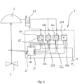
- the field device 7 is designed as a positioner.
- three are occupied by an electronic and/or pneumatic component, namely an I/P converter 55a, 55b, 55c, with one of the modular slots 23d being occupied by an empty module 57.
- the empty module 57 and the modular slot 23d are matched to one another in such a way that the pneumatic input interface 25d is hermetically sealed and the electrical contacts 33d, 35d are covered to prevent short circuits.
- the latter recognizes via the electrical lines from and to the microprocessor 21 whether a modular slot is occupied and with which electronic and/or pneumatic component.
- the microprocessor 21 also recognizes which type of I/P converter 55a to 55c (for example relating to the air capacity) is inserted in the respective slot 23a to c.
- the microprocessor 21 transfers an electrical signal via its output O 1 to the I/P converter 55a, which transmits a pneumatic output signal S 1 via forwards the field output A 1 directly to the pneumatic actuator 3.
- the I/P converter 55b According to the electrical signal via the output O 2 , the I/P converter 55b generates a second pneumatic output signal S 2 , which reaches a volume flow amplifier 61 via the field output A 2 , which amplifies the pneumatic output signal S 2 and transmits it via corresponding pneumatic lines to the Actuator 3 continues.
- the I/P converter arranged in the slot 23c When signaled by the microprocessor 21, the I/P converter arranged in the slot 23c generates a pneumatic output signal S 3 via the output O 3 , which is fed to a quick vent valve 63 via the field output A 3 .
- the I/P converter 55c controls the air vent 63 in such a way that when there is a predetermined drop in the pneumatic output signal S 3 , the air vent 63 causes the pneumatic lines to the actuator 3 to be vented, so that there is atmospheric pressure at the actuator 3 . In this way, the control valve 5 can reach a safety position, for example, by spring forces acting in the actuator 3 .
- the microprocessor 21 can receive electrical signals via its inputs I 1-3 which, for example, can make statements about the outlet pressure S 1 to S 3 . Alternatively, the microprocessor 21 can also receive information about the type of electronic and/or pneumatic component that is used in the slot 23a to 23c via the corresponding inputs I 1-3 . The microprocessor 21 can also recognize whether a dummy module 57 is inserted in the slot 57d.
- an electrical output stage 65 (converting the electrical input signal into an electrical output signal according to a predetermined conversion routine) is employed.
- the electrical signal obtained by the microprocessor via the output O 1 is converted to an electrical output signal S 1 and transmitted via the field output A 1 to an external solenoid valve 67 arranged outside the field device housing 17 .
- the output stage 65 is designed to seal the pneumatic input interface 25a of the slot 23a in an airtight manner.
- an I/P converter 55b is used, which supplies a pneumatic output signal S 2 to the solenoid valve 67 via the field output A 2 , which supplies the pneumatic Output signal to the actuator 3 forwards.
- the I/P converter 55c used in the modular slot 23c generates a further pneumatic output signal S 3 which, like the pneumatic output signal S 2 , is fed to the actuator 3 via the external solenoid valve 67 .
- the I/P converter 55c can have the same pneumatic air capacity as the I/P converter 55b. Alternatively, a smaller or larger air capacity can be provided for the I/P converter 55c to optimize the position control. It is then the microprocessor 21 that selects which of the two I/P converters 55b or 55c or even both are to be responsible for the position of the control valve 5.
- the fourth slot 23d is occupied by a modular, interchangeable electronic data memory M, which stores all the electronic signals from the field device 7, in particular from the microprocessor 21, for later reading.
- the digital signal transmission runs via electrical lines that are connected to the signal input I 4 and the signal output O 4 of the microprocessor 21 .
- the data memory M is designed in such a way that the pneumatic output interface 25d of the slot 23d is hermetically sealed.
- FIG 5 Another possible application of the electropneumatic field device 7 according to the invention is shown, namely for pneumatic coupling to a double-acting pneumatic actuator 71.
- the pneumatic double-acting actuator 71 actuates a control valve 5 in a translatory manner and has two pneumatic working chambers 73, 75, which are operated at different pressures P 1 , P 2 can be acted upon individually.
- the working chambers 73, 75 are pneumatically separated from one another by a displaceable piston 77.
- Both pneumatic working chambers 73, 75 are connected to a pair of electronic and/or pneumatic components in slots 23a, b and 23c, d, which are each occupied by an I/P converter 55a to d.
- the pressure P 1 in the working chamber 75 is controlled by the I/P converters 55a, 55b.
- the I/P converter 55a generates a pneumatic output signal S 1 which is fed directly to the working chamber 75 of the actuator 71 via the field output A 1 .
- the I/P converter 55b generates a second pneumatic output signal S 2 , which is fed via the field outlet A 2 to a quick-acting air vent 81 and, in the event of a drop, causes the pneumatic lines to be vented to the working chamber 75 of the actuator 3 . In the case of venting, the pneumatic working chamber 75 is at atmospheric pressure.
- the I/P converter 55c in slot 23c produces a third pneumatic output signal S 3 which establishes a substantially inverted waveform compared to the pneumatic output signal S 1 of the I/P converter 55a.
- the pneumatic output signal S 3 is supplied to the actuator 71 directly from the field output A 3 .
- the I/P converter 55d generates a fourth pneumatic output signal S 4 , which is fed via the field output A 4 to a quick-acting air vent 83 and controls this in such a way that when the pneumatic output signal S 4 drops, the quick-acting air vent 83 starts venting the pneumatic connections to the pneumatic Working chamber 73 of the actuator 71 causes. In this case, too, the pneumatic working chamber 73 is at atmospheric pressure.
- FIG 6 an alternative assignment of the slots 23a to 23d and different external pneumatic actuators for a pneumatic double-acting actuator 71 is shown. As in the execution after the figure 5 the slots 23 b and 23 d are occupied by an I/P converter 55b or 55d.
- the pneumatic converters 55b, 55d are designed and controlled by the microprocessor 21 in such a way that opposing outlet pressures S 2 and S 4 are realized.
- the pneumatic output signals S 2 and S 4 are fed to external solenoid valves 85 and 87 positioned outside of the field device housing 17 .
- electrical output stages 65a and 65c are used, which are similar to the embodiment according to figure 4 act.
- the electrical output stages 65a and 65c can switch the external solenoid valves 85 and 87 independently of the pneumatic output signals A 2 and A 4 .
- the field device 7 as a position controller can be reconfigured in such a way that the previously inverted electropneumatic slot module is used as a second module in a single-acting position controller.
- the field device works in the same direction as the first pair of plug-in modules to increase the flow rate. This results in a doubled air output, which enables increased control accuracy through the decoupled control of the two pairs of plug-in modules.
- a pneumatic power generator can also be used in one of the slots 23a to 23d in all of the designs.
- the power generator can be used to supply all electronic and/or pneumatic components of the field device 7 with power.
Description
- Die Erfindung betrifft ein elektropneumatisches Feldgerät, wie einen elektropneumatischen Stellungsregler, einen I/P-Umformer oder dergleichen. Das elektropneumatische Feldgerät dient häufig als Steuergerät zum Steuern eines pneumatischen Stellantriebs einer prozesstechnischen Anlage beispielsweise der Petrochemie, der Lebensmittelindustrie oder dergleichen, der wiederum ein Stellventil zum Regeln einer Prozessfluidströmung betätigt.
- Das elektropneumatische Feldgerät hat wenigstens einen elektrischen Feldeingang, über den das Feldgerät ein elektrisches Feldeingangssignal empfängt, das beispielsweise im Falle eines pneumatisch betriebenen Stellventils als Soll-Stell-Signal gebildet sein kann. Das Feldeingangssignal kann beispielsweise ein analoges 4-20mA Stromsignal oder auch ein digitales Feldbussignal wie Profibus PA, Foundation Fieldbus, ASI oder Devicenet sein. Des Weiteren hat das elektropneumatische Feldgerät wenigstens eine Elektronik- und/oder Pneumatikkomponente, die beispielsweise ein elektropneumatischer Wandler, ein Datenspeicher, ein pneumatischer Stromgenerator und/oder ein Mikroprozessor sein kann. Es sei klar, dass das elektropneumatische Feldgerät mehrere Elektronik- und/oder Pneumatikkomponenten, wie mehrere elektropneumatischen Wandler, Mikroprozessoren, elektrische Schalter, Datenspeicher und/oder pneumatische Stromgeneratoren, aufweisen kann. Die wenigstens eine Elektronik- und/oder Pneumatikkomponente ist mit dem wenigstens einen elektrischen Feldeingang verbunden, um das elektrische Feldeingangssignal zu erhalten. Es ist bekannt, insbesondere bei einem Stellungsregler als Feldgerät, dass zwischen dem elektrischen Feldeingang und der Elektronik- und/oder Pneumatikkomponente eine Steuerungs- und/oder Regelungselektronik geschaltet sein kann. Im Falle eines elektropneumatischen Wandlers als die wenigstens eine Elektronik- und/oder Pneumatikkomponente ist der elektropneumatische Wandler mit dem pneumatischen Versorgungseingang des Feldgeräts pneumatisch gekoppelt. Das Feldgerät hat üblicherweise einen pneumatischen Feldausgang, an dem anhand des empfangenen Feldeingangssignals ein pneumatisches Feldausgangssignal beispielsweise zum Steuern des pneumatischen Stellantriebs abgegeben werden kann.
-
EP 2 258 952 A2 betrifft eine piezopneumatische Ventileinheit sowie einen pneumatischen Stellungsregler mit einem pneumatischen Arbeitsglied und einer auf dieses wirkenden piezopneumatischen Ventileinheit. -
EP 1 632 679 A1 betrifft einen elektropneumatischen Stellungsregler mit einem Ventil zur Druckluftaufteilung auf zwei Abluftanschlüsse für ein daran anschließbares Stellgerät. -
EP 1 515 050 A2 offenbart ein Steuergerät mit einer Basis, an der mindestens ein Bestückungsplatz vorgesehen ist, der mit einer an einen in der Basis verlaufenden internen elektrischen Bus angeschlossenen ersten elektrischen Zentralschnittstelle ausgestattet ist, und mit mindestens einem elektrischen Anschlussmodul, das ein lösbares Anschließen vom Steuergerät wegführender elektrischer Kabel ermöglichende elektrische Ein- und/oder Ausgänge aufweist und das lösbar an dem mindestens einen Bestückungsplatz montierbar ist, wobei es eine sich bei der Montage und Demontage des elektrischen Anschlussmoduls selbsttätig bezüglich der ersten elektrischen Zentralschnittstelle kontaktierende bzw. trennende zweite elektrische Zentralschnittstelle aufweist. -
DE 10316129 A1 offenbart ein Diagnosemodul und ein Steuergerät für eine Ventilbatterie. - Aus
DE 10 2008 053 844 A1 ist ein elektropneumatisches Feldgerät bekannt, bei dem mehrere Elektronik- und/oder Pneumatikkomponenten, wie ein elektronischer Regler, ein U/I-Wandler, ein I/P-Wandler, ein Leistungsverstärker, sowie ein Umkehrverstärker, eingesetzt werden können. Ein Umkehrverstärker findet dann Anwendung, wenn das elektropneumatische Feldgerät auf einen doppelt-wirkenden pneumatischen Stellantrieb zugreift. - Aus
EP 1 138 994 A2 ist ein Stellungsregler zum Steuern und/oder Regeln eines pneumatischen Stellantriebs bekannt. Der Stellungsregler hat ein Hauptgehäuse und eine abnehmbare Wartungskassette, deren Innenraum in ein Abteil für elektropneumatische Bauelemente und ein Elektronikabteil unterteilt ist. Die gesamte Wartungskassette ist aus Instandhaltungsgründen von dem Hauptgehäuse abnehmbar. - Es ist Aufgabe der Erfindung, das bekannte elektropneumatische Feldgerät dahingehend zu verbessern, dass ein wirtschaftlicher Aufwand für den Betreiber einer prozesstechnischen Anlage bei der funktionalen Einstellung und Auslegung des elektropneumatischen Feldgeräts deutlich verringert wird.
- Diese Aufgabe wird durch die Merkmale von Anspruch 1 gelöst. Danach hat das erfindungsgemäße elektropneumatische Feldgerät, wie der elektropneumatische Stellungsregler, der I/P-Umformer oder dergleichen, wenigstens einen elektrischen Feldeingang, einen pneumatischen Versorgungseingang, wenigstens eine Elektronik- und/oder Pneumatikkomponente, wie einen elektropneumatischen Wandler, vorzugsweise mehrere elektropneumatische Wandler, einen Mikroprozessor, einen Datenspeicher, einen pneumatischen Stromerzeuger und/oder dergleichen. Die wenigstens eine Elektronik- und/oder Pneumatikkomponente ist mit dem wenigstens einen elektrischen Feldeingang sowie gegebenenfalls mit dem pneumatischen Versorgungseingang verbunden. Außerdem hat das pneumatische Feldgerät einen Feldausgang, an dem anhand eines über den wenigstens einen elektrischen Feldeingang empfangenen Feldsignals, insbesondere Stell- und/oder Regelsignals, ein Feldausgangssignal abgebbar ist. Erfindungsgemäß hat das elektropneumatische Feldgerät eine Gruppe bestehend aus wenigstens zwei modularen Elektronik- und/oder Pneumatikkomponenten unterschiedlicher Funktionalität und wenigstens einem modularen Steckplatz zur Belegung mit jeweils einer Elektronik- und/oder Pneumatikkomponente. Die wenigstens zwei Elektronik- und/oder Pneumatikkomponenten der Gruppe und der wenigstens eine Steckplatz sind derart modular aufeinander abgestimmt, dass deren elektrische und gegebenenfalls pneumatische Schnittstelle bei Belegung des Steckplatzes jeweils funktions- und betriebssicher ineinander übergeben. In der belegten Position im Steckplatz liegen sich die Schnittstellen der eingesetzten Elektronik- und/oder Pneumatikkomponente sowie die Schnittstelle des Steckplatzes diametral gegenüber, so dass ein elektrischer Kontakt und gegebenenfalls eine pneumatische, druckverlustlose Kopplung hergestellt ist. Das erfindungsgemäße elektropneumatische Feldgerät kann auch Elektronik- und/oder Pneumatikkomponenten aufweisen, die nicht in einem modularen Steckplatz angeordnet sind. Ein modularer Steckplatz dient zur Aufnahme einer singulären modularen Elektronik- und/oder Pneumatikkomponente. Der modulare Steckplatz soll von einer Außenseite des Feldgeräts einfach zugänglich sein. Diejenigen Elektronik- und/oder Pneumatikkomponenten der Gruppe, die nicht eingesetzt sind, können an der Außenseite des Gehäuses an jeweiligen zu dem modularen Steckplatz formkomplementären, insbesondere elektrisch blinden Lagerplätzen für einen späteren Einsatz in einem modularen Steckplatz bevorratet sein.
- Der Feldausgang des erfindungsgemäßen elektropneumatischen Feldgeräts kann sowohl pneumatisch als auch elektrisch ausgeführt sein und wird vorzugsweise durch eine der Elektronik- und/oder Pneumatikkomponenten in dem modularen Steckplatz gebildet. Im Falle eines elektrischen Feldausgangs kann ein elektropneumatischer Wandler extern, also außerhalb des Feldgerätgehäuses, vorgesehen sein, der auf der Basis des elektrischen Feldausgangssignals ein pneumatisches Signal zur Abgabe beispielsweise an den pneumatischen Stellantrieb erzeugt.
- Der modulare Steckplatz ist dazu ausgelegt, eine einzelne modulare Elektronik- und/oder Pneumatikkomponente aus der Gruppe von Elektronik- und/oder Pneumatikkomponenten unterschiedlicher Funktionalität, wie ein oder mehrere elektropneumatische Wandler, ein oder mehrere Mikroprozessoren, ein oder mehrere Datenspeicher, ein oder mehrere pneumatische Stromgeneratoren und/oder dergleichen, unter Herstellung einer elektrischen Verbindung an den jeweiligen elektrischen Schnittstellen und gegebenenfalls unter Herstellung einer pneumatischen Verbindung zwischen den jeweiligen pneumatischen Schnittstellen austauschbar aufzunehmen. Da die wenigstens zwei Elektronik- und/oder Pneumatikkomponenten austauschbar an dem erfindungsgemäßen elektropneumatischen Feldgerät vorgesehen sind, ist der wenigstens eine Steckplatz von außen (bezüglich des Feldgerätgehäuses) leicht zugänglich ausgeführt. Auf diese Weise hat das erfindungsgemäße elektropneumatische Feldgerät eine hohe Modularität, die ein Anlagenbetreiber oder auch Anlagenbauer nutzen kann, um sich ohne großen Montageaufwand auf sich ändernde Prozessverhältnisse der Anlage einzustellen. Bekannte Stellungsregler leiden an dem Nachteil, dass durch fest implementierte I/P-Wandler die Luftleistung des Feldgeräts unveränderbar festgelegt, insbesondere beschränkt, ist. Durch die erfindungsgemäße Maßnahme, eine Modularität insbesondere bezüglich sämtlicher Elektronik- und/oder Pneumatikkomponenten, wie dem elektropneumatischen Wandler, dem Datenspeicher, dem pneumatischen Stromerzeuger, dem Mikroprozessor und/oder dergleichen, zu schaffen, ist es möglich, beispielsweise die Luftleistung des Feldgeräts deutlich zu erhöhen oder zu reduzieren, aber auch die Regelungsroutine durch Austausch des Regelungsmikroprozessors zu verändern, eine autarke Stromerzeugung bereitzustellen und/oder durch Austausch des pneumatischen Stromgenerators zu verändern, Daten zum Aufspielen und Abspeichern durch Austausch von Datenspeichern wunschgemäß einzusetzen, ohne das Feldgerät und/oder dessen Umgebung manipulieren zu müssen. Insofern benötigt der Anlagenbauer mit dem erfindungsgemäßen elektropneumatischen Feldgerät keinen hohen zeitlichen und konstruktiven Aufwand, geschweige denn bedarf es einer Unterbrechung des Betriebs der prozesstechnischen Anlage, wenn er eine Betriebsänderung des elektropneumatischen Feldgeräts in einer oder mehreren Funktionalitäten gewünscht ist. Was die Austauschbarkeit des elektropneumatischen Wandlers betrifft, hat das erfindungsgemäße elektropneumatische Feldgerät den Vorteil, nicht notwendigerweise einen separaten Volumenverstärker (Booster) in das pneumatische Leitungssystem einsetzen zu müssen, wenn die Luftleitung des installierten elektropneumatischen Wandlers nicht mehr ausreichen sollte.
- Vorzugsweise ist es vorstellbar, dass das elektropneumatische Feldgerät gemäß der Erfindung wenigstens zwei modulare Steckplätze aufweist, die beide mit einem unterschiedlichen elektropneumatischen Wandler belegt sind. Eine Steuerungselektronik, die beispielsweise innerhalb eines Gehäuses des elektropneumatischen Feldgeräts fest und unaustauschbar montiert ist, aber auch im Wege des modularen Steckplatzes gegen eine andere Stellungselektronik ausgetauscht werden kann, wählt je nach Betriebsbedingungen einen der beiden Druckwandler aus, um die für den Funktionsbetrieb des elektropneumatischen Feldgeräts am besten geeignete Druckwandlerparameter nutzen zu können. In der Zwischenzeit bleibt der nicht ausgewählte elektropneumatische Wandler in dem Steckplatz in einer passiven Warteposition. Sollte beispielsweise bei einem Zwei- oder Mehr-Platz-Feldgerät eine dritte elektropneumatische Funktionalität genutzt werden, besteht die Möglichkeit, einen der den Steckplatz belegenden elektropneumatischen Wandler gegen einen dritten elektropneumatischen Wandler mit der gewünschten Funktion auszutauschen, der beispielsweise an einem blinden Lagerplatz an der Außenseite des Feldgerätgehäuses bevorratet war.
- Sämtliche Elektronik- und/oder Pneumatikkomponenten der Gruppe, die zur Verfügung stehen, um an den wenigstens einen modularen Steckplatz eingesetzt zu werden, sind beispielsweise dadurch modular gegenüber dem Steckplatz abgestimmt, das der Steckplatz eine weibliche Aussparungsform aufweist, die zumindest teilweise formkomplementär zum männlichen Außenprofil der jeweiligen Elektronik- und/oder Pneumatikkomponente ist. Die aufeinander abgestimmten Formen sind derart gewählt, dass nur eine Einsteckposition zugelassen ist, um das Adaptieren der elektrischen Schnittstelle und gegebenenfalls der pneumatischen Schnittstelle zu gewährleisten.
- Bevorzugte Ausgestaltungen der Erfindung sind in den Unteransprüchen 2 bis 14 angegeben.
- Bei einer bevorzugten Ausgestaltung der Erfindung hat der wenigstens eine Steckplatz einen Andockmechanismus, der eine Form- und/oder Kraftschlusseinrichtung, wie eine Rasteinrichtung, insbesondere eine manuell betätigbare Klemme oder eine Schraubverbindung zum lösbaren Befestigen der jeweiligen Elektronik- und/oder Pneumatikkomponente in dem modularen Steckplatz umfasst. Die Form- und/oder Kraftschlusseinrichtung kann vorzugsweise dazu ausgelegt sein, eine Vorspannung der jeweiligen Elektronik- und/oder Pneumatikkomponente mitzuteilen, so dass die jeweiligen elektrischen Schnittstellen und gegebenenfalls die pneumatischen Schnittstellen des Steckplatzes und der Elektronik- und/oder Pneumatikkomponente gegeneinander gedrückt werden, um den elektrischen Kontakt sowie gegebenenfalls den pneumatischen Anschluss herzustellen.
- Bei einer bevorzugten Ausführung der Erfindung ist der wenigstens eine Steckplatz durch eine Vertiefung oder Aussparung insbesondere in einer Gehäusewand des Feldgeräts realisiert. In der Vertiefung kann die Elektrokomponente formschlüssig aufgenommen sein.
- Bei einer Weiterbildung der Erfindung hat das elektropneumatische Feldgerät mehrere modulare Steckplätze. Die mehreren modularen Steckplätze können entweder durch gleiche Elektronik- und/oder Pneumatikkomponenten insbesondere unterschiedlicher Funktionsweise, oder unterschiedliche Elektronik- und/oder Pneumatikkomponenten belegt sein. Die Belegung hängt von der gewünschten Charaktereigenschaft des Feldgeräts, beispielsweise der Luftleistung ab.
- Erfindungsgemäß hat der wenigstens eine Steckplatz eine elektrische, mit dem elektrischen Feldeingang verbundene Schnittstelle und eine pneumatische, mit dem pneumatischen Versorgungseingang des Feldgeräts verbundene Schnittstelle zum pneumatischen Ankoppeln eines pneumatischen Anschlusses der Elektronik- und/oder Pneumatikkomponente, wenn beispielsweise ein I/P-Wandler als Elektronik- und/oder Pneumatikkomponente verwendet werden soll.
- Erfindungsgemäß hat der wenigstens eine Steckplatz einen der pneumatischen Schnittstelle zugeordneten Verschluss, welcher im unbelegten Zustand und im Falle der Belegung mit einer Elektro- und/oder Pneumatikkomponente ohne Pneumatikfunktion des wenigstens einen Steckplatzes dessen pneumatische Schnittstelle im Wesentlichen luftdicht verschließt. In einem mit einem elektropneumatischen Wandler belegten Zustand des wenigstens einen Steckplatzes ist der Verschluss deaktiviert, so dass ein pneumatischer Anschluss der pneumatischen Versorgung von dem elektropneumatischen Wandler etabliert ist.
- Bei einer bevorzugten Ausführung der Erfindung hat jeder modulare Steckplatz eine elektrische, mit dem wenigstens einen elektrischen Feldeingang verbundene Schnittstelle und gegebenenfalls pneumatische, mit dem pneumatischen Versorgungseingang gekoppelte Schnittstelle. Die jeweilige Schnittstelle ist im angedockten Zustand der jeweiligen Elektronik- und/oder Pneumatikkomponente mit deren elektrischen und gegebenenfalls pneumatischen Anschluss funktionsgemäß verbunden.
- Bei einer bevorzugten Ausführung der Erfindung hat der wenigstens eine modulare Steckplatz jeweils einen modularen Andockmechanismus für die wenigstens eine modulare Elektronik- und/oder Pneumatikkomponente. Der Andockmechanismus ist dazu ausgelegt, die jeweilige Elektronik- und/oder Pneumatikkomponente in dem modularen Steckplatz insbesondere mittels einer Einrastung fest aufzunehmen und zu halten sowie gegebenenfalls für einen Austausch der Elektronik- und/oder Pneumatikkomponenten insbesondere zerstörungsfrei und vorzugsweise manuell, insbesondere ohne Spezialwerkzeug, zu lösen.
- Bei einer Weiterbildung der Erfindung hat der wenigstens modulare Steckplatz jeweils eine Identifizierungseinrichtung zum Erfassen des Typs/der Bauart der Elektronik- und/oder Pneumatikkomponente. Vorzugsweise ist die Identifizierungseinrichtung dazu ausgelegt, im Falle der Belegung des Steckplatzes mit einer Elektronik- und/oder Pneumatikkomponente ohne Pneumatikfunktion, wie einem Mikroprozessor, den luftdichten Verschluss der pneumatischen Schnittstelle des Steckplatzes zu aktivieren. Dazu kann beispielsweise die Identifizierungseinrichtung einen elektrischen und/oder mechanischen Sensor aufweisen, der gegebenenfalls über eine Elektronikeinheit, wie einen insbesondere fest installierten Mikroprozessor mit einem an dem Steckplatz angeordneten pneumatischen Verschluss funktionsgemäß gekoppelt ist.
- Bei einer Weiterbildung der Erfindung hat das Feldgerät eine Elektronikeinheit, wie einen Mikroprozessor, die als modulare Elektronik- und/oder Pneumatikkomponente in dem wenigstens einen modularen Steckplatz einsetzbar ist. Die Elektronikeinheit kann allerdings auch als fest installiertes nicht modulares Glied innerhalb des Feldgerätgehäuses fest installiert sein. Die Elektronikeinheit ist dazu ausgelegt, die Belegung des wenigstens einen modularen Steckplatzes mit unterschiedlichen Elektronik- und/oder Pneumatikkomponenten zu erkennen und entsprechend das am Feldgerät empfangene Feldeingangssignal der jeweiligen Elektronik- und/oder Pneumatikkomponente zuzuordnen.
- Bei einer bevorzugten Ausführung der Erfindung hat das elektropneumatische Feldgerät ein insbesondere fluiddicht abschließbares Gehäuse. Das Gehäuse kann in einem ersten Abteil eine insbesondere fest installierte Reglerelektronik aufnehmen. Bei einer bevorzugten Ausführung der Erfindung ist der wenigstens eine modulare Steckplatz an einer Außenwand einer Trennwand eines Abteils oder an einer Außenwand des Gehäuses eingerichtet, so dass eine Bedienperson dadurch einen manuellen Zugriff auf den wenigstens einen Steckplatz hat.
- Bei einer bevorzugten Ausführung der Erfindung kann die Anordnung mehrere modulare Steckplätze oder auch nur einen modularen Steckplatz mittels eines von dem Gehäuse abnehmbaren Gehäuseteils, wie eines Deckels, insbesondere zur Bildung eines zweiten Gehäuseteils vorzugsweise fluiddicht verschließbar, aufweisen.
- Bei einer Weiterbildung der Erfindung hat der wenigstens eine modulare Steckplatz ein elektrisches Anschlussbild und gegebenenfalls ein pneumatisches Anschlussbild. Die wenigstens eine Elektronik- und/oder Pneumatikkomponente kann ein elektrisches Gegenanschlussbild und gegebenenfalls ein pneumatisches Gegenanschlussbild aufweisen, wobei das Gegenanschlussbild spiegelbildlich zum Anschlussbild ausgeführt ist, so dass beim einfachen Einsetzen der Elektronik- und/oder Pneumatikkomponente in den Steckplatz unmittelbar der elektrische Kontakt sowie gegebenenfalls der pneumatische Anschluss hergestellt ist. Bei einer bevorzugten Ausführung der Erfindung hat das elektropneumatische Feldgerät wenigstens ein Paar modulare Steckplätze, vorzugsweise drei Paar modulare Steckplätze, wobei sämtliche Steckplätze mit einem elektropneumatischen Wandler belegt sind und insbesondere ein elektropneumatischer Wandler des Steckplatzpaares direkt mit einer pneumatischen Arbeitskammer eines Stellventils verbindbar ist und der andere elektropneumatische Wandler des Steckplatzpaars mit einem pneumatischen Wirkglied, wie einem Entlüfter oder einem Schnellentlüfter pneumatisch koppelbar ist, wobei der Schnellentlüfter derart an die pneumatische Arbeitskammer angeschlossen ist, dass bei Empfang eines insbesondere vorbestimmten pneumatischen Ausgangssignals des anderen elektropneumatischen Wandler des Steckplatzpaars die pneumatische Arbeitskammer des Stellantriebs entlüftet werden kann, vorzugsweise mit einem Atmosphärendruckausgang des pneumatischen Wirkglieds gekoppelt wird, wobei im Falle eines doppelt wirkenden pneumatischen Stellantriebs die zweite Arbeitskammer durch ein zweites Paar entsprechend belegte Steckplätze ansteuerbar ist. Bei einer bevorzugten Ausführung der Erfindung hat das elektropneumatische Feldgerät ein Paar modulare Steckplätze, wobei der eine Steckplatz mit einem elektropneumatischen Wandler und der andere Steckplatz mit einer elektrischen Ausgangsstufe belegt sind, wobei der elektropneumatische Wandler an einen externen, insbesondere außerhalb eines Gehäuses des Feldgeräts angeordneten elektropneumatischen Wandler, wie einem Magnetventil, angeschlossen ist, der mit einer Arbeitskammer eines Stellantriebs verbunden ist, wobei die elektrische Ausgangsstufe mit dem externen elektropneumatischen Wandler derart verbunden ist, dass bei Abgabe eines vorbestimmten elektrischen Signals der externe elektropneumatische Wandler entlüftet wird, wobei im Falle eines doppelt wirkenden, pneumatischen Stellantriebs eine zweites Paar entsprechend belegte Steckplätze zur Ansteuerung der zweiten Arbeitskammer vorgesehen ist.
- Bei einer bevorzugten Ausführung der Erfindung hat das elektropneumatische Feldgerät eine Gruppe aus wenigstens zwei modularen Elektronik- und/oder Pneumatikkomponenten wenigstens einen elektropneumatischen Wandler, wenigstens einen pneumatischen Stromgenerator, wenigstens einen Mikroprozessor, wenigstens eine elektrische Ausgangsstufe, wie wenigstens einen Schalter, und/oder wenigstens einen Datenspeicher.
- Bei einer bevorzugten Ausführung der Erfindung ist die Gehäusestruktur für das elektropneumatische Feldgerät nicht aus einem gemeinsamen Gehäuse für sämtliche Komponenten realisiert, sondern das Gehäuse des elektropneumatischen Feldgeräts ist in wenigstens zwei voneinander getrennte Gehäuseteile aufgeteilt. In einem ersten Gehäuseteil sind insbesondere ausschließlich die Elektronik- und/oder Pneumatikkomponenten in jeweilige Steckplätze anzuordnen, wobei die Steckplätze vorzugsweise von außen erreichbar sein sollen. Bei dem zweiten Gehäuse sind insbesondere lediglich die Steckplätze für Pneumatikkomponenten vorgesehen.
- Beispielsweise kann das Gehäuse für die Elektronik- und/oder Pneumatikkomponenten an einem den Stellantrieb mit dem Stellventilgehäuse verbindenden Joch oder Laterne realisiert sein, wobei die Elektronik -und/oder Pneumatikkomponenten beispielsweise ein Mikrorechner, ein Positionssensor oder dergleichen sein kann. Das zweite Gehäuse für die pneumatischen Elektronik- und/oder Pneumatikkomponenten ist vorzugsweise insbesondere an einer dem Stellventilgehäuse zugewandten Außenwandseite des Stellantriebs angebracht, wobei an dem Gehäuse Elektronikpneumatikkomponenten, wie der I/p-Wandler oder ein Booster, angeordnet sein können.
- Es sei klar, dass die modularen Steckplätze für die Bausteine der Elektronik- und/oder Pneumatikkomponenten passend für jede Elektronikkomponente bzw. Pneumatikkomponente ausgeführt sein sollen.
- Des Weiteren betrifft die Erfindung eine elektropneumatische Baugruppe mit einem Stellventil für eine prozesstechnische Anlage, einem pneumatischen Stellantrieb, insbesondere einen doppelt-wirkenden pneumatischen Stellantrieb oder einen einfach-wirkenden pneumatischen Stellantrieb, zum Stellen eines Stellventils, gegebenenfalls einem Positionssensor zum Erfassen der Position des Stellventils und mit einem elektropneumatischen Feldgerät, wie er oben beschrieben ist.
- Vorzugsweise ist der Positionssensor mit dem elektropneumatischen Feldgerät, insbesondere mit dessen Reglerelektronik, wie dessen Mikroprozessor, signalübertragungsgemäß verbunden.
- Weitere Eigenschaften, Merkmale und Vorteile der Erfindung werden durch die folgende Beschreibung bevorzugter Ausführungen der Erfindung anhand der beiliegenden Zeichnungen deutlich, in denen zeigen:
- Figur 1
- eine schematische Darstellung eines erfindungsgemäßen elektropneumatischen Feldgeräts,
- Figur 2
- eine schematische Perspektivansicht eines einen modularen Steckplatz belegenden, modularen pneumatischen Wandlers,
- Figur 3
- eine schematische Darstellung einer weiteren Ausführung eines nicht erfindungsgemäßen elektropneumatischen Feldgeräts;
- Figur 4
- eine schematische Darstellung einer weiteren Ausführung eines nicht erfindungsgemäßen elektropneumatischen Feldgeräts;
- Figur 5
- eine schematische Darstellung eines erfindungsgemäßen elektropneumatischen Feldgeräts, das an einen doppelt-wirkenden pneumatischen Stellantrieb angeschlossen ist; und
- Figur 6
- eine weitere bevorzugte Ausführung eines nicht erfindungsgemäßen elektropneumatischen Feldgeräts, das an einen doppelt-wirkenden pneumatischen Stellantrieb angeschlossen ist.
- In
Figur 1 ist eine pneumatisch betriebene, erfindungsgemäße Stellventilanordnung, die zur Regelung einer Prozessfluidströmung einer nicht dargestellten prozesstechnischen Anlage, wie einer petrochemischen Anlage, einer Lebensmittel verarbeitenden Anlage, wie einer Brauerei, oder dergleichen, eingesetzt wird, im allgemeinen mit der Bezugsziffer 1 versehen. Diese Stellventilanordnung 1 umfasst als Hauptbestandteile einen pneumatischen Stellantrieb 3, ein Stellventil 5, das zum Regeln der Prozessfluidströmung der nicht dargestellten prozesstechnischen Anlage von dem Stellantrieb 3 betätigt ist, und ein als Stellungsregler ausgeführtes elektropneumatisches Feldgerät 7, das über ein pneumatisches Leitungssystem 11 an dem pneumatischen Stellantrieb 3 angeschlossen ist. - Das Stellventil 5 ist mit dem pneumatischen Stellantrieb 3 über eine Spindel oder Welle 13 mechanisch verbunden. Ein insbesondere mechanisch arbeitender Positionssensor 15, der teilweise innerhalb eines Gehäuses 17 des elektropneumatischen Feldgeräts 7 angeordnet ist, greift die Momentanstellung X des Stellventils 5 ab. Das Gehäuse kann ein fluiddicht abschließbaren Hohlraum aufweisen, in dem unter anderem elektrische Leitungen, pneumatische Verbindungsleitungen und/oder ein Mikroprozessor untergebracht sind. Es sei klar, dass das Gehäuse 17 des erfindungsgemäßen elektropneumatischen Feldgeräts auch lediglich durch eine Leiterplatte mit daran angebrachten pneumatischen Leitungen ausgebildet sein kann.
- Der Positionssensor 15 gibt ein Positionssignal an einen Mikroprozessor 21 ab, der darstellungsgemäß in einem Innenraum des Feldgerätgehäuses 17 untergebracht ist und über einen Feldeingang 18 am Feldgerätgehäuse ein Soll-Stell-Signal w von einer nicht näher dargestellten Leitstelle der Anlage empfängt. Das elektropneumatische Feldgerät 7 hat neben dem elektrischen Feldeingang 18 einen pneumatischen Feldeingang 33 und vier optional einsetzbare pneumatische Feldausgänge A1-a.
- Das elektropneumatische Feldgerät 7 oder der Stellungsregler hat vier im Wesentlichen gleich aufgebaute von außen frei zugängliche Steck- oder Einschubplätze 23a, 23b, 23c, 23d, welche optional mit vier einzelnen Elektronik- und/oder Pneumatikkomponenten unterschiedlichster Bauart belegbar sind. Die Elektronik- und/oder Pneumatikkomponente kann ein I/P-Wandler, ein Datenspeicher, ein pneumatisch betriebener Stromgenerator, der Mikroprozessor 21 und/oder ein Elektronikschalter sein, wobei auch Elektronik- und/oder Pneumatikkomponenten gleicher Bauart unterschiedlicher Funktionsweise in den Steckplätzen eingesetzt werden können. Jeder Steckplatz kann allerdings nur eine einzelne Elektronik- und/oder Pneumatickomponente aufnehmen. Die Steckplätze 23a bis 23d sind derart modular angepasst, dass sie je nachdem, welche vorbestimmte elektronische Komponente eingesetzt wird die Funktion der Elektronik- und/oder Pneumatikkomponente durch Herstellung von Kommunikationsleitungen zu den jeweils anderen Bauelementen gewährleistet.
- Das elektropneumatische Feldgerät 7 kann auch nicht dargestellte Lageraufnahmen zu Bevorratung von nicht eingesetzten modularen Elektronik- und/oder Pneumatikkomponenten aufweisen, welche Lageraufnahme im wesentlichen formidentisch zu den Steckplätzen 23a bis 23d ausgebildet sind, allerdings keine elektrische oder pneumatische Schnittstelle aufweisen.
- Das elektropneumatische Feldgerät 7 hat eine Gruppe aus wenigstens zwei Elektronik- und/oder Pneumatikkomponenten, die ausgewählt werden können, in die jeweiligen Steckplätze eingesetzt zu werden. Die Elektronik- und/oder Pneumatikkomponenten sind in
Figur 1 nicht näher dargestellt. - Jeder einzelne Steckplatz 23a bis 23d des Feldgeräts besitzt eine pneumatische Eingangsschnittstelle 25a bis 25d, die über eine innerhalb des Gehäuses 17 verlaufende Versorgungsleitung 27 via den pneumatischen Feldeingang 33 an eine pneumatische Versorgungsquelle 31 von beispielsweise konstant 6 bar (PZ) angeschlossen ist. Die Steckplätze 23a bis 23d umfassen zusätzlich eine elektrische Ausgangsschnittstelle 33a bis 33d, die über elektrische Leitungen mit jeweils einem Mikroprozessoreingang I1-4 verbunden ist. Zudem hat jeder Steckplatz 23a bis 23d eine elektrische Eingangsschnittstelle 35a bis 35d, die über elektrische Leitungen mit einem jeweiligen Mikroprozessorausgang O1-4 verbunden ist. Auf diese Weise können die in den Steckplätzen 23a bis 23d platzierten Elektronik- und/oder Pneumatikkomponenten mit dem Mikroprozessor 21 kommunizieren, damit beispielsweise ein Regelsignal von dem Mikroprozessor 21 an den jeweiligen Steckplatz 23a bis 23d abgebbar sind. Der Mikroprozessor 21 erkennt über die Kommunikationsleitungen, welche Bauart und Typ Elektronik- und/oder Pneumatikkomponente an dem jeweiligen Steckplatz 23a bis 23d eingesetzt ist und/oder ob der Steckplatz 23a bis 23d unbelegt ist.
- Schließlich hat jeder Steckplatz 23a bis 23d eine Ausgangsschnittstelle 37a bis 37d, über die Ausgangssignale entweder elektrischer Natur (nicht in
Figur 1 dargestellt) oder pneumatischer Natur S1-4 an dem jeweiligen Feldgerätausgang A1 bis A4 abgegeben werden kann. Bei der inFigur 1 dargestellten Ausführung sind die Feldgerätausgänge A1-4 pneumatisch genutzt und können ein entsprechend pneumatisches Steuersignal S1-4 über entsprechende pneumatische Leitungen 41 an den pneumatischen Stellantrieb 3 abgeben. Da alle pneumatischen Drücke der einzelnen, in dem Steckplatz 23a bis 23d eingesetzten I/P-Wandler die gleiche Wirkrichtung in das Arbeitsvolumen des pneumatischen Stellantriebs aufweisen, erhöht sich deutlich die Luftleistung durch die multiple, entkoppelte Ansteuerung der I/P-Wandler, wodurch die Regelgenauigkeit bei der Stellung des Stellventils erhöht wird. Werden vier I/P-Wandler der gleichen Luftleistung verwendet, wird die dem pneumatischen Stellantrieb zugeführte Luftleistung vervierfacht. - Je nach dem, beispielsweise welche Luftleistung dem elektropneumatischen Feldgerät 7 zugeordnet sein soll, können die Steckplätze 23a bis 23d auch mit vier unterschiedlichsten I/P-Wandlern belegt sein. Wird ein Steckplatz 23a bis 23d mit einem I/P-Wandler belegt, so erkennt der Mikroprozessor 21 die Belegung über beispielsweise eine geeignete, nicht dargestellte Sensorik und/oder über die jeweilige die elektrische Eingangsschnittstelle 35a bis 35d mit dem elektrischen Mikroprozessorausgang O1-4 verbindenden Leitung.
- Sollten mehrere Steckplätze 23a bis 23d mit unterschiedlichen I/P-Wandlern belegt sein, so kann der Mikroprozessor 21 nur einen dieser zum Betrieb des Stellantriebs 3 auswählen. Wählt der Mikroprozessor 21 beispielweise den in dem Steckplatz 23c angeordneten I/P-Wandler mit einer bestimmten Luftleistung aus, so gibt der Mikroprozessor 21 über seinen Ausgang I3 ein entsprechendes elektrisches Regelsignal an den in dem Steckplatz 23c angeordneten I/P-Wandler ab, der ein entsprechendes Luftdrucksignal S3 über die pneumatische Ausgangsschnittstelle 37c an den pneumatischen Stellantrieb 3 abgibt, wobei die restlichen I/P-Wandler in den Steckplätzen 23a, 23b, 23d durch den Mikroprozessor 21 deaktiviert oder zumindest unangesprochen bleiben.
- Ist beispielsweise einer der Steckplätze 23a bis 23d nicht belegt, so erkennt dies der Mikroprozessor 21. Er lässt dann automatisch veranlassen, entweder selbst durch eine entsprechendes Regelsignal des Mikroprozessors 21 oder durch eine selbständig arbeitende Verschlusseinrichtung (nicht dargestellt), dass die jeweilige pneumatische Eingangsschnittstelle 55a bis 55d des unbelegten Steckplatzes geschlossen ist. Gleiches gilt auch, wenn anstatt eines I/P-Wandlers eine reine Elektronikkomponente, bzw. eine Elektronik- und /oder Pneumatikkomponente ohne Pneumatikfunktion, wie ein elektrischer Speicher, den jeweiligen Steckplatz 23a bis 23d belegt.
- Wie bereits angedeutet, können anstatt des I/P-Wandlers in dem Steckplatz 23a bis 23d andere Elektronik- und/oder Pneumatikkomponenten eingesetzt werden. Beispielsweise kann der Steckplatz 23a mit dem Mikroprozessor 21 belegt sein, der mit den jeweiligen anderen Steckplätzen kommunizieren kann. Außerdem kann der Steckplatz 23b durch einen I/P-Wandler, wie oben beschrieben, belegt sein, während der Steckplatz 23c durch einen pneumatischen Stromgenerator zur elektrischen Versorgung der anderen Elektronik- und/oder Pneumatickomponente eingesetzt sein. Der Steckplatz 23d kann durch einen elektrischen Datenspeicher oder eine elektrische Schaltung belegt sein, welche mit einer externen elektrischen Baukomponente verbindbar ist.
- In
Figur 2 ist schematisch in einer perspektivischen Darstellung einer der Steckplätze 23 zum Teil angedeutet, der zur Realisierung der Modularität steckplatzseitig einen Andockmechanismus 43 aufweist, der dazu ausgelegt ist, die Elektronik- und/oder Pneumatikkomponente 45, die inFigur 2 als Würfel repräsentiert ist, lösbar aber fest aufzunehmen, wobei in der aufgenommenen Position ein elektrischer Kontakt zwischen dem elektrischen Eingang 47 und dem elektrischen Ausgang 49 der Elektronik- und/oder Pneumatikkomponente 45 und der jeweiligen elektrischen Ausgangs- bzw. Eingangsschnittstelle (33a bis 33d bzw. 35 a bis 35d) etabliert ist. Gleiches gilt für die pneumatische Verbindung mit der Versorgungsleitung 27 zwischen dem pneumatischen Anschluss 51 der Elektronik- und/oder Pneumatikkomponente 45 und der nicht näher dargestellten elektropneumatischen Eingangsschnittstelle 25a bis 25d des Steckplatzes 23a bis 23d. - Der Andockmechanismus 43 umfasst eine Rasteinrichtung, der dazu dient, die Elektronik- und/oder Pneumatikkomponente 45 mittels Vorspannung in dem Steckplatz 23a bis 23d gegen die jeweiligen steckplatzseitigen Schnittstellen zu halten. Die Rasteinrichtung kann mittels manueller Betätigung gelöst werden, so dass die Elektronik- und/oder Pneumatikkomponente 45 aus dem Steckplatz 23a bis 23d entnommen werden und gegen eine andere Elektronik- und/oder Pneumatikkomponente 45 ausgetauscht werden können. Die Rasteinrichtung kann aus mehreren Rasthaken 53 gebildet sein, die fest an dem Gehäuse 17 im Bereich des Steckplatzes von außen betätigbar angebracht sind.
- Die Steckplätze 23 sowie die darin eingesetzten Elektronik- und/oder Pneumatikkomponenten 45 können zum Schutz vor äußeren Einflüssen mittels eines an dem Gehäuse 17 lösbar befestigbaren, insbesondere verschraubbaren Deckel fluiddicht eingekapselt werden. Bei Austausch der modularen Elektronik- und/oder Pneumatikkomponente 45 kann der nicht dargestellte Deckel abgenommen werden, damit der modulare Austauschvorgang durchgeführt werden kann.
- In den
Figuren 3 bis 6 sind unterschiedliche Belegungsversionen des elektropneumatischen Feldgeräts 7 dargestellt, wobei das elektropneumatische Feldgerät 7 mit unterschiedlichen elektropneumatischen externen Wirkgliedern außerhalb des Feldgerätgehäuses 17 verbunden sein kann. - In
Figur 3 ist das Feldgerät 7 als Stellungsregler ausgeführt. Von den vier belegbaren modularen Steckplätzen 23a bis 23d sind drei mit einer Elektronik- und/oder Pneumatikkomponente, nämlich mit einem I/P-Wandler 55a, 55b, 55c belegt, wobei einer der modularen Steckplätze 23d mit einem Leermodul 57 belegt ist. Das Leermodul 57 und der modulare Steckplatz 23d sind derart aufeinander abgestimmt, dass die pneumatische Eingangsschnittstelle 25d luftdicht verschlossen ist und die elektrischen Kontakte 33d, 35d kurzschlusssicher abgedeckt sind. - Über die elektrischen Leitungen von und zu dem Mikroprozessor 21 erkennt letzterer, ob eine modularer Steckplatz belegt ist und mit welcher Elektronik- und/oder Pneumatikkomponente. Der Mikroprozessor 21 erkennt auch, welcher Typ von I/P-Wandler 55a bis 55c (beispielsweise betreffend die Luftleistung) in den jeweiligen Steckplatz 23a bis c eingesetzt ist.
- Aufgrund des Soll-Stell-Signals w transferiert der Mikroprozessor 21 über seinen Ausgang O1 ein elektrisches Signal an den I/P-Wandler 55a, der ein pneumatisches Ausgangsignal S1 über den Feldausgang A1 direkt an den pneumatischen Stellantrieb 3 weiterleitet. Entsprechend dem elektrischen Signal über den Ausgang O2 erzeugt der I/P-Wandler 55b ein zweites pneumatisches Ausgangssignal S2, das über den Feldausgang A2 zu einem Volumenstromverstärker 61 gelangt, der das pneumatische Ausgangssignal S2 verstärkt und über entsprechende pneumatische Leitungen an den Stellantrieb 3 weiterführt.
- Der in dem Steckplatz 23c angeordnete I/P-Wandler erzeugt auf Signalisierung durch den Mikroprozessor 21 via Ausgang O3 ein pneumatisches Ausgangsignal S3, dass über den Feldausgang A3 einem Schnellentlüfter 63 zugeführt wird. Der I/P-Wandler 55c steuert den Schnellentlüfter 63 derart an, dass bei einem insbesondere vorbestimmten Abfall des pneumatischen Ausgangssignals S3 der Schnellentlüfter 63 ein Entlüften der pneumatischen Leitungen zum Stellantrieb 3 bewirkt, so dass an dem Stellantrieb 3 Atmosphärendruck herrscht. Damit kann das Stellventil 5 eine Sicherheitsstellung beispielsweise durch in dem Stellantrieb 3 wirkende Federkräfte erreichen.
- Der Mikroprozessor 21 kann über seine Eingänge I1-3 elektrische Signale erhalten, die beispielsweise Aussagen über den Ausgangsdruck S1 bis S3 machen können. Alternativ kann der Mikroprozessor 21 auch über die entsprechenden Eingänge I1-3 Informationen über den Typ der Elektronik- und/oder Pneumatikkomponente erhalten, die in dem Steckplatz 23a bis 23c verwendet wird. Die Mikroprozessor 21 kann auch erkennen, ob ein Leermodul 57 in dem Steckplatz 57d eingesetzt ist.
- In der Ausführung nach
Figur 4 ist eine alternative Belegung des Feldgeräts 7 dargestellt. Durch die unterschiedliche Belegung der Steckplätze 23a bis 23d wird dem Feldgerät 7 eine unterschiedliche Funktionalität zugeordnet. - In dem Steckplatz 23a des Feldgeräts 7 nach
Figur 4 ist eine elektrische Ausgangstufe 65 (Umwandlung des elektrischen Eingangssignals in ein elektrisches Ausgangssignal gemäß einer vorbestimmten Umwandlungsroutine) eingesetzt. Das von dem Mikroprozessor über den Ausgang O1 erhaltene elektrische Signal wird an ein elektrisches Ausgangssignal S1 umgewandelt und über den Feldausgang A1 an ein externes, außerhalb des Feldgerätgehäuses 17 angeordnetes Magnetventil 67 übertragen. Dabei ist die Ausgangsstufe 65 dazu ausgelegt, die pneumatische Eingangsschnittstelle 25a des Steckplatzes 23a luftdicht zu verschließen. In dem zweiten Steckplatz 23b ist ein I/P-Wandler 55b eingesetzt, der ein pneumatisches Ausgangssignal S2 über den Feldausgang A2 dem Magnetventil 67 zuführt, der das pneumatische Ausgangssignal an den Stellantrieb 3 weiterleitet. Der in dem modularen Steckplatz 23c eingesetzten I/P-Wandler 55c erzeugt ein weiteres pneumatisches Ausgangssignal S3, das wie das pneumatische Ausgangssignal S2 über das externe Magnetventil 67 dem Stellantrieb 3 zugeführt ist. Der I/P-Wandler 55c kann die gleiche pneumatische Luftleistung wie der I/P-Wandler 55b aufweisen. Alternativ kann für eine Optimierung der Stellungsregelung eine kleinere oder eine größere Luftleistung für den I/P-Wandler 55c vorgesehen sein. Es ist dann der Mikroprozessor 21, der auswählt, welcher der beiden I/P-Wandler 55b oder 55c oder sogar beide für die Stellung des Stellventils 5 verantwortlich sein sollen. - Der vierte Steckplatz 23d ist mit einem modular austauschbaren, elektronischen Datenspeicher M belegt, der sämtliche elektronische Signale des Feldgeräts 7, insbesondere des Mikroprozessors 21, für eine spätere Auslesung speichert. Die digitale Signalübertragung läuft über elektrische Leitungen, die mit dem Signaleingang I4 und dem Signalausgang O4 des Mikroprozessors 21 verbunden sind. Der Datenspeicher M ist bezüglich des modularen Steckplatzes 23d derart ausgestaltet, dass die pneumatische Ausgangsschnittstelle 25d des Steckplatzes 23d luftdicht verschlossen ist.
- In
Figur 5 ist eine weitere Einsatzmöglichkeit des erfindungsgemäßen elektropneumatischen Feldgeräts 7 dargestellt, nämlich zur pneumatischen Ankopplung an einen doppelt-wirkenden pneumatischen Stellantrieb 71. Der pneumatisch doppelt-wirkende Stellantrieb 71 betätigt translatorisch ein Stellventil 5 und hat zwei pneumatische Arbeitskammern 73, 75, die mit unterschiedlichen Drücken P1, P2 individuell beaufschlagbar sind. Die Arbeitskammern 73, 75 sind durch einen verschiebbaren Kolben 77 voneinander pneumatisch getrennt. - Beide pneumatischen Arbeitskammern 73, 75 sind an ein Paar Elektronik- und/oder Pneumatikkomponenten in den Steckplätzen 23a, b bzw. 23 c, d angeschlossen, die jeweils mit einem I/P-Wandler 55a bis d belegt sind.
- Der Druck P1 in der Arbeitskammer 75 wird von dem I/P-Wandlern 55a, 55b gesteuert. Der I/P-Wandler 55a erzeugt ein pneumatisches Ausgangssignal S1, das über den Feldausgang A1 direkt der Arbeitskammer 75 des Stellantriebs 71 zugeführt wird. Der I/P-Wandler 55b erzeugt ein zweites pneumatisches Ausgangssignal S2, das über den Feldausgang A2 einem Schnellentlüfter 81 zugeführt ist und bei einem Abfall das Entlüften der pneumatischen Leitungen hin zur Arbeitskammer 75 des Stellantriebs 3 bewirkt. Im Entlüftungsfall liegt die pneumatische Arbeitskammer 75 auf Atmosphärendruck.
- Der I/P-Wandler 55c im Steckplatz 23c erzeugt ein drittes pneumatisches Ausgangssignal S3, das einen im wesentlichen invertierten Signalverlauf im Vergleich zu dem pneumatischen Ausgangssignal S1 des I/P-Wandlers 55a etabliert. Das pneumatische Ausgangssignal S3 wird direkt von dem Feldausgang A3 dem Stellantrieb 71 zugeführt. Der I/P-Wandler 55d erzeugt ein viertes pneumatisches Ausgangssignal S4, das via dem Feldausgang A4 einem Schnellentlüfter 83 zugeführt wird und diesen derart ansteuert, dass bei Abfall des pneumatischen Ausgangssignals S4 der Schnellentlüfter 83 das Entlüften der pneumatischen Verbindungen hin zur pneumatischen Arbeitskammer 73 des Stellantriebs 71 bewirkt. Auch in diesem Fall liegt dann die pneumatische Arbeitskammer 73 auf Atmosphärendruck.
- Die Implementierung noch zusätzlicher externer, außerhalb des Feldgerätgehäuses 17 angeordneter Schnellentlüfter ermöglicht eine weitaus präzisere und schnellere pneumatische Regelung von doppelt-wirkenden Stellantrieben. Während Schnellentlüfter 81, 83 bauartbedingt eine Hysterese besitzen, kann durch die getrennte Ansteuerung mittels der I/P-Wandler 55b und 55d dieses Überschwingen verhindert werden. Dabei kann im Entlüftungsfall das dem Schnellentlüfter 81, 83 ansteuernde pneumatische Ausgangssignal A2 und A4 vor dem pneumatischen Ausgangssignal A1 und A3 vom Entlüften zum Belüften umgesteuert werden, so dass das Entlüften ohne Überschwingungen abgebremst wird. Die Unabhängigkeit der pneumatischen Ausgangssignale A1-4 bietet somit eine präzise Möglichkeit der Regelung pneumatischer Ausgangsgrößen. Insbesondere die Kombination kleiner Luftleistung mit großer Luftleistung kann zum Realisieren kurzer Stellzeiten höchst genau durchgeführt werden.
- In
Figur 6 ist eine alternative Belegung der Steckplätze 23a bis 23d und unterschiedliche externe pneumatische Wirkglieder für einen pneumatisch doppelt-wirkenden Stellantrieb 71 dargestellt. Wie bei der Ausführung nach derFigur 5 sind die Steckplätze 23 b und 23 d mit einem I/P-Wandler 55b bzw. 55d belegt. - Die pneumatischen Wandler 55b, 55d sind derart ausgelegt und von dem Mikroprozessor 21 angesteuert, dass gegenläufige Ausgangsdrücke S2 und S4 realisiert werden. Die pneumatischen Ausgangsignale S2 und S4 werden externen, außerhalb des Feldgerätgehäuses 17 positionierte Magnetventile 85 bzw. 87 zugeführt. In den Steckplätzen 23a und 23c sind elektrische Ausgangsstufen 65a bzw. 65c eingesetzt, die ähnlich wie die der Ausführung gemäß
Figur 4 fungieren. Die elektrischen Ausgangsstufen 65a und 65c können die externen Magnetventile 85 bzw. 87 unabhängig von den pneumatischen Ausgangssignalen A2 und A4 schalten. - Je nachdem welches der Magnetventile 85, 87 geschaltet wird, kann damit eine unterschiedliche Endlage für das Stellventil 5 erreicht werden. Es ist außerdem möglich, dass zur Steigerung der Stellgeschwindigkeit je nach gewünschter Richtung der Ventilbewegung eines der beiden Magnetventile 87, 85 kurzzeitig geschaltet wird und damit die jeweilige Arbeitskammer 73, 77 entlüftet wird, um die Stellbewegung in Richtung der entlüfteten Kammer zu beschleunigen. Dabei können Verzögerungszeiten, die für die Stellungsregelung wichtig sein können, beispielsweise bei der Inbetriebnahme gemäß einem beispielsweise im Mikroprozessor vorprogrammierten Initialisierungsvorgang, gelernt werden und für eine spätere Stellungsregelung können diese Daten verwendet werden.
- Das Feldgerät 7 als Stellungsregler kann erfindungsgemäß derart umkonfiguriert werden, dass das vorher invertiert arbeitende elektropneumatische Steckplatzmodul als ein zweites Modul in einem einfach wirkenden Stellungsregler verwendet wird. Dabei arbeitet das Feldgerät in gleicher Wirkrichtung wie das erste Steckmodulpaar zur Erhöhung der Durchflussmenge. Damit ergibt sich eine verdoppelte Luftleistung, welche durch die entkoppelte Ansteuerung der beiden Steckmodulpaare eine erhöhte Regelgenauigkeit ermöglicht.
- Es sei klar, dass bei allen Ausführungen auch ein pneumatischer Stromgenerator in einen der Steckplätze 23a bis 23d eingesetzt werden kann. Der Stromgenerator kann dazu dienen, sämtliche Elektronik- und/oder Pneumatikkomponenten des Feldgeräts 7 mit Strom zu versorgen.
-
- 1
- Stellventilanordnung
- 3
- pneumatischer Stellantrieb
- 5
- Stellventil
- 7
- elektropneumatisches Feldgerät
- 11
- pneumatische Leitungssystem
- 13
- Spindel
- 15
- Positionssensor
- 17
- Gehäuse
- 18, 33
- Feldeingang
- 21
- Mikroprozessor
- 23a,b,c,d
- Steck- und Einschubplätze
- 25a,b,c,d
- pneumatische Eingangsschnittstelle
- 33a,b,c,d
- elektrische Ausgangschnittstelle
- 35a,b,c,d
- elektrische Eingangschnittstelle
- 37a,b,c,d
- Ausgangsschnittstelle
- 55a,b,c,d
- I/p-Wandler
- 27
- Versorgungsleitung
- 31
- Versorgungsquelle
- 41
- Leitungen
- 43
- Andockmechanismus
- 45
- Elektronikkomponente
- 47
- elektrischer Eingang
- 49
- elektrischer Ausgang
- 61
- Volumenstromverstärker
- 63
- Schnellentlüfter
- 65a,c
- elektrische Ausgangsstufe
- 67
- Magnetventil
- 71
- Stellantrieb
- 73, 75
- Arbeitskammer
- 77
- Kolben
- 81, 83
- Schnellentlüfter
- 85,87
- Magnetventil
- A1-4
- Feldgerätausgänge
- I1-4
- Mikroprozessoreingang
- M
- Datenspeicher
- O1-4
- Mikroprozessorausgang
- P1, 2
- Druck
- PZ
- Versorgungsdruck
- S1-4
- Ausgangssignal
- W
- Soll-Stell-Signal
- X
- Momentanstellung
Claims (14)
- Elektropneumatisches Feldgerät (7) umfassend:- wenigstens einen elektrischen Feldeingang (18);- einen pneumatischen Versorgungseingang (33);- wenigstens eine Elektronik- und/oder Pneumatikkomponente, die mit dem wenigstens einen elektrischen Feldeingang (18) sowie gegebenenfalls mit dem pneumatischen Versorgungseingang (33) verbunden ist;- wenigstens einen Feldausgang (A1, A2, A3, A4), an dem anhand eines über den wenigstens einen elektrischen Feldeingang (18) empfangenen Feldsignals ein Feldausgangssignal (S1, S2, S3, S4) abgebbar ist; und- eine Gruppe aus wenigstens zwei modularen Elektronik- und/oder Pneumatikkomponenten unterschiedlicher Funktionalität und wenigstens einen modularen Steckplatz (23a-d) zur Belegung mit jeweils einer Elektronik- und/oder Pneumatikkomponente aus der Gruppe, wobei die wenigstens zwei Elektronik- und/oder Pneumatickomponenten und der wenigstens eine Steckplatz derart modular aufeinander abgestimmt sind, dass deren elektrische und gegebenenfalls pneumatische Schnittstellen (33a-d, 35a-d, 25a-d, 37a-d) bei Belegung des Steckplatzes ineinander übergehen;wobei der wenigstens eine Steckplatz eine elektrische, mit dem elektrischen Feldeingang (18) verbundene Schnittstelle (35a-d) und eine pneumatische, mit dem pneumatischen Versorgungseingang (33) verbundene Schnittstelle (25a-d) zum pneumatischen Ankoppeln eines pneumatischen Anschlusses der Elektronik- und/oder Pneumatikkomponente (45) aufweist, dadurch gekennzeichnet, dass der wenigstens eine Steckplatz einen Verschluss aufweist, welcher im unbelegten Zustand und im Falle der Belegung mit einer Elektro- und/oder Pneumatikkomponente ohne Pneumatikfunktion des wenigstens einen Steckplatzes dessen pneumatische Schnittstelle (25a-d) im Wesentlichen luftdicht verschließt und im belegten Zustand mit einer Elektro- und/oder Pneumatikkomponente mit Pneumatikfunktion des wenigstens einen Steckplatzes (23a-d) deaktiviert ist, so dass der pneumatische Anschluss mit dem pneumatischen Versorgungseingang pneumatisch verbunden ist.
- Elektropneumatisches Feldgerät (7) nach Anspruch 1, dadurch gekennzeichnet, dass der wenigstens eine Steckplatz (23a-d) einen Andockmechanismus (43) aufweist, der eine Form- und/oder Kraftschlusseinrichtung zum lösbaren Befestigen der jeweiligen Elektronik- und/oder Pneumatikkomponente (45) in dem modularen Steckplatz umfasst und/oder eine Vorspannung erzeugt, die derart ausgerichtet ist, dass die elektrischen und gegebenenfalls pneumatischen Schnittstellen (33a-d, 25a-d, 35a-d, 37a-d) der Elektronik- und/oder Pneumatickomponente (45) sowie des Steckplatzes gegeneinander gedrückt werden.
- Elektropneumatisches Feldgerät (7) nach Anspruch 1 oder 2, dadurch gekenn- zeichnet, dass der wenigstens eine Steckplatz durch eine Vertiefung realisiert und die Elektronik- und/oder Pneumatikkomponenten (45) der Gruppe jeweils im Wesentlichen formkomplementär zur Vertiefung ausgeführt sind.
- Elektropneumatisches Feldgerät (7) nach Anspruch 1, 2 oder 3, dadurch gekenn- zeichnet, dass es mehrere modulare Steckplätze (23a-d) aufweist.
- Elektropneumatisches Feldgerät (7) nach einem der vorstehenden Ansprüche, dadurch gekennzeichnet, dass der wenigstens eine modulare Streckplatz jeweils einen Andockmechanismus (43) für die wenigstens eine Elektronik- und/oder Pneumatickomponente (45) aufweist, welcher dazu ausgelegt ist, die jeweilige Elektronik- und/oder Pneumatikkomponente (45) in dem modularen Steckplatz (23a-d) fest aufzunehmen und zu halten.
- Elektropneumatisches Feldgerät (7) nach einem der vorstehenden Ansprüche, dadurch gekennzeichnet, dass der wenigstens eine modulare Steckplatz (23a-d) jeweils eine Identifizierungseinrichtung zum Erfassen des Elektronik- und/oder Pneumatickomponententyps umfasst, wobei die Identifizierungseinrichtung dazu ausgelegt ist, im Falle der Belegung des Steckplatzes mit einer Elektronik- und/oder Pneumatikkomponente (45) ohne Pneumatikfunktion, wie einem Mikroprozessor oder Datenspeicher (M), den luftdichten Verschluss der pneumatischen Schnittstelle (25a-d) des Steckplatzes zu aktivieren um die pneumatische Schnittstelle des Steckplatzes im Wesentlichen luftdicht zu verschließen.
- Elektropneumatisches Feldgerät (7) nach Anspruch 6, dadurch gekennzeichnet, dass die Identifizierungseinrichtung einen elektrischen und/oder mechanischen Sensor aufweist, der mit einem an dem Steckplatz angeordneten pneumatischen Verschluss funktionsgemäß gekoppelt ist, und/oder dass es eine Elektronikeinheit, wie einen Mikroprozessor (21), aufweist, der dazu ausgelegt ist, die Belegung des wenigstens einen modularen Steckplatzes (23a-d) mit unterschiedlichen Elektronik- und/oder Pneumatikkomponenten (45) zu erkennen und entsprechend das am Feldgerät empfangenen Feldeingangssignal (w) der jeweiligen Elektronik- und/oder Pneumatikkomponente (45) zuzuordnen.
- Elektropneumatisches Feldgerät (7) nach einem der vorstehenden Ansprüche, dadurch gekennzeichnet, dass es ein abschließbares Gehäuse (17) aufweist, das in einem ersten Abteil eine Reglerelektronik aufnimmt und/oder an einer Außenseite dessen Trennwand oder einer Außenwand des Gehäuses (17) der wenigstens eine modulare Steckplatz (23a-d) eingerichtet ist, wobei die Anordnung des wenigstens einen modularen Steckplatzes (23a-d) mittels eines von dem Gehäuse (17) abnehmbaren Gehäuseteils verschließbar ist.
- Elektropneumatisches Feldgerät (7) nach einem der vorstehenden Ansprüche, dadurch gekennzeichnet, dass der wenigstens eine modulare Steckplatz (23a-d) ein elektrisches Anschlussbild und ein pneumatisches Anschlussbild aufweist und dass die wenigstens eine Elektronik- und/oder Pneumatikkomponente (45) ein elektrisches und gegebenenfalls ein pneumatisches Gegenanschlussbild aufweist, wobei das Gegenanschlussbild spiegelbildlich zum Anschlussbild ausgeführt ist.
- Elektropneumatisches Feldgerät (7) nach einem der vorstehenden Ansprüche, dadurch gekennzeichnet, dass es wenigstens ein Paar modulare Steckplätze (23a-d) aufweist, wobei sämtliche Steckplätze mit einem elektropneumatischen Wandler (55a-d) belegt sind und ein elektropneumatischer Wandler (55a, 55c) des Steckplatzpaares direkt mit einer pneumatischen Arbeitskammer (73, 75) eines Stellventils (5) verbindbar ist und der andere elektropneumatische Wandler (55b, 55d) des Steckplatzpaars mit einem pneumatischen Wirkglied, wie einem Entlüfter oder einem Schnellentlüfter (81, 83) pneumatisch koppelbar ist, wobei der Schnellentlüfter (81, 83) derart an die pneumatische Arbeitskammer (73, 75) anschliessbar ist, dass bei Empfang eines pneumatischen Ausgangssignals (52, 54) des anderen elektropneumatischen Wandlers (55b, 55d) des Steckplatzpaars die pneumatische Arbeitskammer (73, 75) des Stellantriebs (71) entlüftet werden kann, wobei im Falle eines doppelt wirkenden pneumatischen Stellantriebs (71) die zweite Arbeitskammer (73, 75) durch ein zweites Paar entsprechend belegte Steckplätze (23c, 23d) ansteuerbar ist.
- Elektropneumatisches Feldgerät (7) nach einem der vorstehenden Ansprüche, dadurch gekennzeichnet, dass das wenigstens eine Paar (23a-d) modulare Steckplätze aufweist, wobei der eine Steckplatz (23b, 23d) mit einem elektropneumatischen Wandler (55b, 55d) und der andere Steckplatz (23a, 23c) mit einer elektrischen Ausgangsstufe (65a, 65c) belegt sind, wobei der elektropneumatische Wandler (55b, 55d) an einen externen elektropneumatischen Wandler angeschlossen ist, der mit einer Arbeitskammer (73, 75) eines Stellantriebs (71) verbindbar ist, wobei die elektrische Ausgangsstufe (65a, 65c) mit dem externen elektropneumatischen Wandler derart verbunden ist, dass bei Abgabe eines vorbestimmten elektrischen Signals (S1, S3) der externe elektropneumatische Wandler entlüftet wird, wobei im Falle eines doppelt wirkenden, pneumatischen Stellantriebs (71) ein zweites Paar (23a, 23d, 23c, 23b) entsprechend belegte Steckplätze zur Ansteuerung der zweiten Arbeitskammer (75, 73) vorgesehen ist.
- Elektropneumatisches Feldgerät (7) nach einem der vorstehenden Ansprüche, dadurch gekennzeichnet, dass die Gruppe aus wenigstens zwei modularen Elektronik- und/oder Pneumatikkomponenten wenigstens einen elektropneumatischen Wandler, wenigstens einen pneumatischen Stromgenerator, wenigstens einen Mikroprozessor, wenigstens eine elektrische Ausgangsstufe (65), wie wenigstens einen Schalter, und/oder wenigstens einen Datenspeicher (M), umfasst.
- Elektropneumatisches Feldgerät (7) nach Anspruch 8, dadurch geke nnzeichnet, dass das Gehäuse (17) mindestens zweigeteilt ist und in einem ersten Gehäuseabteil Elektronik- und/oder Pneumatikkomponenten und in einem zweiten Gehäuseabteil lediglich Pneumatikkomponenten angeordnet sind.
- Elektropneumatische Baugruppe mit einem Stellventil (5) für eine prozesstechnische Anlage, einem pneumatischen Stellantrieb (3, 71) zum Stellen des Stellventils (5), einem Positionssensor (15) zum Erfassen der Position (X) des Stellventils (5) und einem nach einem der vorstehenden Ansprüche ausgebildeten Feldgerät (7), wobei der Positionssensor (15) mit dem elektropneumatischen Feldgerät (7) signalübertragungsgemäß verbunden ist.
Applications Claiming Priority (1)
| Application Number | Priority Date | Filing Date | Title |
|---|---|---|---|
| DE102012021387.5A DE102012021387B3 (de) | 2012-10-31 | 2012-10-31 | Elektropneumatisches Feldgerät und elektropneumatische Baugruppe |
Publications (3)
| Publication Number | Publication Date |
|---|---|
| EP2728201A2 EP2728201A2 (de) | 2014-05-07 |
| EP2728201A3 EP2728201A3 (de) | 2017-08-23 |
| EP2728201B1 true EP2728201B1 (de) | 2023-07-12 |
Family
ID=49322129
Family Applications (1)
| Application Number | Title | Priority Date | Filing Date |
|---|---|---|---|
| EP13004694.9A Active EP2728201B1 (de) | 2012-10-31 | 2013-09-27 | Elektropneumatisches Stellgerät und elektropneumatische Baugruppe |
Country Status (3)
| Country | Link |
|---|---|
| US (1) | US9506482B2 (de) |
| EP (1) | EP2728201B1 (de) |
| DE (1) | DE102012021387B3 (de) |
Families Citing this family (17)
| Publication number | Priority date | Publication date | Assignee | Title |
|---|---|---|---|---|
| DE102014211258A1 (de) * | 2014-06-12 | 2015-12-17 | Materialforschungs- und -prüfanstalt an der Bauhaus-Universität Weimar | Vorrichtung zur Erzeugung definierter Druckverläufe |
| DE102014013098B3 (de) * | 2014-09-03 | 2015-12-03 | Samson Aktiengesellschaft | Stellungsregler für ein pneumatisches Stellgerät |
| DE102015102486B4 (de) * | 2015-02-20 | 2021-01-28 | Krohne Messtechnik Gmbh | Feldgerät zur Bestimmung einer Messgröße und Verfahren zum Kommunizieren |
| DE102015007147A1 (de) | 2015-06-03 | 2016-12-08 | Samson Aktiengesellschaft | Elektro-pneumatischer Aktor |
| DE102016100919B3 (de) * | 2016-01-20 | 2017-05-18 | Samson Aktiengesellschaft | Pneumatischer Volumenstromverstärker sowie Feldgerät und Feldgeräteanordnung mit einem pneumatischen Volumenstromverstärker |
| JP2017194122A (ja) * | 2016-04-21 | 2017-10-26 | アズビル株式会社 | ポジショナおよびバルブ制御システム |
| EP3252360B1 (de) * | 2016-06-03 | 2018-12-12 | Alfa Laval Corporate AB | Steuerung der zufuhr von luft an ein pneumatisches ventilstellglied |
| DE102016117073A1 (de) | 2016-09-12 | 2018-03-15 | Samson Aktiengesellschaft | Steuerungs-Interaktions-Verfahren und Kommunikationsvorrichtung zum Durchführen einer Steuerungs-Interaktion zwischen einer Bedienelektronik und einem Stellgerät |
| DE102016118975A1 (de) | 2016-10-06 | 2018-04-12 | Samson Aktiengesellschaft | Stellungsregler und Stellgerät |
| DE202016106017U1 (de) | 2016-10-26 | 2018-01-28 | Samson Aktiengesellschaft | Elektropneumatischer Stellungsregler und Feldgerät mit einem elektropneumatischen Stellungsregler |
| US11226215B2 (en) * | 2016-11-03 | 2022-01-18 | Vega Grieshaber Kg | Modular field device kit and method of assembly |
| WO2018202290A1 (de) * | 2017-05-03 | 2018-11-08 | Festo Ag & Co. Kg | Elektropneumatisches steuergerät und damit ausgestattete prozesssteuervorrichtung |
| US10670054B2 (en) * | 2017-10-25 | 2020-06-02 | Dresser, Llc | Constructing valve positioners for hazardous areas |
| DE202018105714U1 (de) | 2018-10-05 | 2018-11-19 | Samson Ag | Luftleistungsverstärker für einen Antrieb eines Stellventils |
| DE102020101177A1 (de) * | 2020-01-20 | 2021-07-22 | Sisto Armaturen S.A. | System zum Betrieb einer Pneumatikeinrichtung |
| DE102022122576A1 (de) * | 2022-09-06 | 2024-03-07 | Samson Aktiengesellschaft | Stellungsregler |
| DE102022122565A1 (de) * | 2022-09-06 | 2024-03-07 | Samson Aktiengesellschaft | Stellungsregler und Verfahren zum Herstellen eines Stellungsreglers |
Citations (2)
| Publication number | Priority date | Publication date | Assignee | Title |
|---|---|---|---|---|
| DE10316129A1 (de) * | 2003-04-03 | 2004-10-28 | Festo Ag & Co. | Diagnosemodul und Steuergerät für eine Ventilbatterie |
| EP1515050A2 (de) * | 2003-04-01 | 2005-03-16 | FESTO AG & Co | Steuergerät |
Family Cites Families (18)
| Publication number | Priority date | Publication date | Assignee | Title |
|---|---|---|---|---|
| DE4227201C2 (de) * | 1992-08-17 | 1995-12-21 | Centralair Sa | Modulsystem für lineare pneumatische oder elektro-pneumatische Stellventile |
| US5439021A (en) | 1992-09-09 | 1995-08-08 | Fisher Controls International, Inc. | Electro-pneumatic converter |
| DE29516247U1 (de) | 1995-10-13 | 1996-01-25 | Kieselmann Gmbh | Steuerkopf für Armaturen mit pneumatischem Antrieb für die Lebensmittel- und Getränkeindustrie |
| DE19636418C2 (de) * | 1996-09-07 | 1998-06-10 | Kaemmer Ventile Gmbh | Pneumatischer Stellantrieb |
| JP3399878B2 (ja) | 1999-07-16 | 2003-04-21 | エスエムシー株式会社 | リレー装置付きマニホールド形電磁弁 |
| US6422532B1 (en) * | 2000-03-01 | 2002-07-23 | Invensys Systems, Inc. | Severe service valve positioner |
| DE20307308U1 (de) | 2003-05-09 | 2003-07-03 | Dbt Autom Gmbh | Steuergerät für den untertägigen Bergbau |
| DE102004035047B4 (de) | 2004-07-20 | 2006-06-01 | Samson Ag | Stellungsregelungssystem für ein von einem pneumatischen Stellantrieb betriebenes Stellorgan |
| DE102004043062B3 (de) | 2004-09-06 | 2006-04-13 | Siemens Ag | Elektropneumatischer Stellungsregler |
| DE202005015791U1 (de) | 2005-10-07 | 2005-12-08 | Bürkert Werke GmbH & Co. KG | Modulsystem aus anreihbaren Einzelmodulen |
| DE202006000916U1 (de) | 2006-01-20 | 2006-03-09 | Bürkert Werke GmbH & Co. KG | Steuerkopf-Modulsystem für eine pneumatische Stellvorrichtung |
| US7938145B2 (en) * | 2006-06-02 | 2011-05-10 | Smc Corporation Of America | Coupler including electrical and pneumatic interfaces |
| CN101410767B (zh) | 2007-03-29 | 2012-07-18 | 费斯托股份有限两合公司 | 用于阀组的调节器模块 |
| DE102008007651B3 (de) * | 2008-02-06 | 2009-09-24 | Samson Aktiengesellschaft | Stellungsregler für doppeltwirkenden, pneumatischen Stellantrieb, doppeltwirkender, pneumatischer Stellantrieb und Verfahren zum Betreiben des doppeltwirkenden, pneumatischen Stellantriebs |
| DE102008053844B4 (de) * | 2008-10-30 | 2010-09-30 | Samson Ag | Elektro-pneumatisches System, Anordnung und Verfahren zum Steuern eines doppelt wirkenden pneumatischen Stellantriebs |
| DE102009023706A1 (de) * | 2009-06-03 | 2010-12-16 | Hoerbiger Automatisierungstechnik Holding Gmbh | Pneumatischer Stellungsregler mit piezopneumatischer Ventileinheit |
| DE102009029495A1 (de) | 2009-09-16 | 2011-03-24 | Endress + Hauser Conducta Gesellschaft für Mess- und Regeltechnik mbH + Co. KG | Messumformer für ein Multisensorsystem, insbesondere als Feldgerät für die Prozessautomatisierungstechnik und Verfahren zum Betreiben des Messumformers |
| DE102010035102A1 (de) | 2010-08-23 | 2012-04-19 | Bürkert Werke GmbH | Steuergerät für fluidische Systeme |
-
2012
- 2012-10-31 DE DE102012021387.5A patent/DE102012021387B3/de active Active
-
2013
- 2013-09-27 EP EP13004694.9A patent/EP2728201B1/de active Active
- 2013-10-25 US US14/063,303 patent/US9506482B2/en active Active
Patent Citations (2)
| Publication number | Priority date | Publication date | Assignee | Title |
|---|---|---|---|---|
| EP1515050A2 (de) * | 2003-04-01 | 2005-03-16 | FESTO AG & Co | Steuergerät |
| DE10316129A1 (de) * | 2003-04-03 | 2004-10-28 | Festo Ag & Co. | Diagnosemodul und Steuergerät für eine Ventilbatterie |
Also Published As
| Publication number | Publication date |
|---|---|
| EP2728201A3 (de) | 2017-08-23 |
| EP2728201A2 (de) | 2014-05-07 |
| US20140116241A1 (en) | 2014-05-01 |
| US9506482B2 (en) | 2016-11-29 |
| DE102012021387B3 (de) | 2014-02-13 |
Similar Documents
| Publication | Publication Date | Title |
|---|---|---|
| EP2728201B1 (de) | Elektropneumatisches Stellgerät und elektropneumatische Baugruppe | |
| EP3359351B1 (de) | Greifvorrichtung mit integriertem regler | |
| EP0608245B1 (de) | Elektro-pneumatische steuereinrichtung | |
| EP2047340B1 (de) | Ventilbatterie mit einem reglermodul | |
| EP1872019B1 (de) | Antriebsvorrichtung mit stellungsregler | |
| DE102008019501B4 (de) | Elektrohydraulische Steueranordnung | |
| EP2728202B1 (de) | Pneumatisches Antriebssystem und Verfahren zum Betreiben des pneumatischen Antriebssystems | |
| EP1975418B1 (de) | Ventilbatterie | |
| DE112016005625T5 (de) | Vorrichtung zum Spritzgießen von Kunststoffmaterialien | |
| DE102017207414A1 (de) | Pneumatische Steuervorrichtung und damit ausgestattete Prozesssteuervorrichtung | |
| EP1316732B1 (de) | Fluidbetätigte Arbeitsvorrichtung | |
| DE10245815A1 (de) | Druckluftsteuervorrichtung und Luftfederungsanlage für ein Fahrzeug | |
| EP0968372A1 (de) | Plattenartige montagebasis | |
| DE10222890B4 (de) | Elektrische Einrichtung für die Ansteuerung eines Mehrwegeventils mit einer Verschleißzustandserkennung | |
| EP3289229B1 (de) | Ventilanordnung | |
| DE102006006585B3 (de) | Wandler eines elektrischen Eingangssignals in ein pneumatisches Ausgangssignal | |
| EP0962663B1 (de) | Steuereinricthung für fluidbetätigte Verbraucher | |
| EP3523101B1 (de) | Greifvorrichtung mit schaltmodul | |
| EP0621407B1 (de) | Ventilstation | |
| EP3318769B1 (de) | Elektropneumatischer stellungsregler und feldgerät mit einem eletropneumatischen stellungsregler | |
| EP3601808B1 (de) | Prozesssteuervorrichtung | |
| EP1275570A2 (de) | Bremsanlage mit elektropneumatischem Modulator | |
| EP2728205A2 (de) | Druckluft-Wartungsgerät und damit ausgestattete Verbrauchersteuervorrichtung | |
| DE102019202898A1 (de) | Antriebssystem | |
| DE102020205446B4 (de) | Arbeitseinrichtung zur Durchführung eines Arbeitsvorgangs und Verfahren zum Betreiben einer Arbeitseinrichtung |
Legal Events
| Date | Code | Title | Description |
|---|---|---|---|
| PUAI | Public reference made under article 153(3) epc to a published international application that has entered the european phase |
Free format text: ORIGINAL CODE: 0009012 |
|
| 17P | Request for examination filed |
Effective date: 20130927 |
|
| AK | Designated contracting states |
Kind code of ref document: A2 Designated state(s): AL AT BE BG CH CY CZ DE DK EE ES FI FR GB GR HR HU IE IS IT LI LT LU LV MC MK MT NL NO PL PT RO RS SE SI SK SM TR |
|
| AX | Request for extension of the european patent |
Extension state: BA ME |
|
| PUAL | Search report despatched |
Free format text: ORIGINAL CODE: 0009013 |
|
| AK | Designated contracting states |
Kind code of ref document: A3 Designated state(s): AL AT BE BG CH CY CZ DE DK EE ES FI FR GB GR HR HU IE IS IT LI LT LU LV MC MK MT NL NO PL PT RO RS SE SI SK SM TR |
|
| AX | Request for extension of the european patent |
Extension state: BA ME |
|
| RIC1 | Information provided on ipc code assigned before grant |
Ipc: F15B 20/00 20060101AFI20170719BHEP Ipc: F15B 5/00 20060101ALI20170719BHEP |
|
| STAA | Information on the status of an ep patent application or granted ep patent |
Free format text: STATUS: REQUEST FOR EXAMINATION WAS MADE |
|
| 17P | Request for examination filed |
Effective date: 20180221 |
|
| RBV | Designated contracting states (corrected) |
Designated state(s): AL AT BE BG CH CY CZ DE DK EE ES FI FR GB GR HR HU IE IS IT LI LT LU LV MC MK MT NL NO PL PT RO RS SE SI SK SM TR |
|
| STAA | Information on the status of an ep patent application or granted ep patent |
Free format text: STATUS: EXAMINATION IS IN PROGRESS |
|
| 17Q | First examination report despatched |
Effective date: 20200615 |
|
| STAA | Information on the status of an ep patent application or granted ep patent |
Free format text: STATUS: EXAMINATION IS IN PROGRESS |
|
| REG | Reference to a national code |
Ref country code: DE Ref legal event code: R079 Ref document number: 502013016424 Country of ref document: DE Free format text: PREVIOUS MAIN CLASS: F15B0020000000 Ipc: F15B0005000000 Ref country code: DE Ref legal event code: R079 Free format text: PREVIOUS MAIN CLASS: F15B0020000000 |
|
| RIC1 | Information provided on ipc code assigned before grant |
Ipc: F15B 13/00 20060101ALN20230131BHEP Ipc: F15B 5/00 20060101AFI20230131BHEP |
|
| GRAP | Despatch of communication of intention to grant a patent |
Free format text: ORIGINAL CODE: EPIDOSNIGR1 |
|
| STAA | Information on the status of an ep patent application or granted ep patent |
Free format text: STATUS: GRANT OF PATENT IS INTENDED |
|
| RIC1 | Information provided on ipc code assigned before grant |
Ipc: F15B 13/00 20060101ALN20230302BHEP Ipc: F15B 5/00 20060101AFI20230302BHEP |
|
| INTG | Intention to grant announced |
Effective date: 20230316 |
|
| GRAS | Grant fee paid |
Free format text: ORIGINAL CODE: EPIDOSNIGR3 |
|
| GRAA | (expected) grant |
Free format text: ORIGINAL CODE: 0009210 |
|
| STAA | Information on the status of an ep patent application or granted ep patent |
Free format text: STATUS: THE PATENT HAS BEEN GRANTED |
|
| AK | Designated contracting states |
Kind code of ref document: B1 Designated state(s): AL AT BE BG CH CY CZ DE DK EE ES FI FR GB GR HR HU IE IS IT LI LT LU LV MC MK MT NL NO PL PT RO RS SE SI SK SM TR |
|
| REG | Reference to a national code |
Ref country code: CH Ref legal event code: EP |
|
| REG | Reference to a national code |
Ref country code: DE Ref legal event code: R096 Ref document number: 502013016424 Country of ref document: DE |
|
| REG | Reference to a national code |
Ref country code: IE Ref legal event code: FG4D Free format text: LANGUAGE OF EP DOCUMENT: GERMAN |
|
| P01 | Opt-out of the competence of the unified patent court (upc) registered |
Effective date: 20230713 |
|
| PGFP | Annual fee paid to national office [announced via postgrant information from national office to epo] |
Ref country code: GB Payment date: 20230920 Year of fee payment: 11 |
|
| REG | Reference to a national code |
Ref country code: LT Ref legal event code: MG9D |
|
| REG | Reference to a national code |
Ref country code: NL Ref legal event code: MP Effective date: 20230712 |
|
| PGFP | Annual fee paid to national office [announced via postgrant information from national office to epo] |
Ref country code: FR Payment date: 20230928 Year of fee payment: 11 Ref country code: DE Payment date: 20230920 Year of fee payment: 11 |
|
| PG25 | Lapsed in a contracting state [announced via postgrant information from national office to epo] |
Ref country code: NL Free format text: LAPSE BECAUSE OF FAILURE TO SUBMIT A TRANSLATION OF THE DESCRIPTION OR TO PAY THE FEE WITHIN THE PRESCRIBED TIME-LIMIT Effective date: 20230712 |
|
| PG25 | Lapsed in a contracting state [announced via postgrant information from national office to epo] |
Ref country code: GR Free format text: LAPSE BECAUSE OF FAILURE TO SUBMIT A TRANSLATION OF THE DESCRIPTION OR TO PAY THE FEE WITHIN THE PRESCRIBED TIME-LIMIT Effective date: 20231013 |
|
| PG25 | Lapsed in a contracting state [announced via postgrant information from national office to epo] |
Ref country code: ES Free format text: LAPSE BECAUSE OF FAILURE TO SUBMIT A TRANSLATION OF THE DESCRIPTION OR TO PAY THE FEE WITHIN THE PRESCRIBED TIME-LIMIT Effective date: 20230712 |
|
| PG25 | Lapsed in a contracting state [announced via postgrant information from national office to epo] |
Ref country code: IS Free format text: LAPSE BECAUSE OF FAILURE TO SUBMIT A TRANSLATION OF THE DESCRIPTION OR TO PAY THE FEE WITHIN THE PRESCRIBED TIME-LIMIT Effective date: 20231112 |
|
| PG25 | Lapsed in a contracting state [announced via postgrant information from national office to epo] |
Ref country code: SE Free format text: LAPSE BECAUSE OF FAILURE TO SUBMIT A TRANSLATION OF THE DESCRIPTION OR TO PAY THE FEE WITHIN THE PRESCRIBED TIME-LIMIT Effective date: 20230712 Ref country code: RS Free format text: LAPSE BECAUSE OF FAILURE TO SUBMIT A TRANSLATION OF THE DESCRIPTION OR TO PAY THE FEE WITHIN THE PRESCRIBED TIME-LIMIT Effective date: 20230712 Ref country code: PT Free format text: LAPSE BECAUSE OF FAILURE TO SUBMIT A TRANSLATION OF THE DESCRIPTION OR TO PAY THE FEE WITHIN THE PRESCRIBED TIME-LIMIT Effective date: 20231113 Ref country code: NO Free format text: LAPSE BECAUSE OF FAILURE TO SUBMIT A TRANSLATION OF THE DESCRIPTION OR TO PAY THE FEE WITHIN THE PRESCRIBED TIME-LIMIT Effective date: 20231012 Ref country code: LV Free format text: LAPSE BECAUSE OF FAILURE TO SUBMIT A TRANSLATION OF THE DESCRIPTION OR TO PAY THE FEE WITHIN THE PRESCRIBED TIME-LIMIT Effective date: 20230712 Ref country code: LT Free format text: LAPSE BECAUSE OF FAILURE TO SUBMIT A TRANSLATION OF THE DESCRIPTION OR TO PAY THE FEE WITHIN THE PRESCRIBED TIME-LIMIT Effective date: 20230712 Ref country code: IS Free format text: LAPSE BECAUSE OF FAILURE TO SUBMIT A TRANSLATION OF THE DESCRIPTION OR TO PAY THE FEE WITHIN THE PRESCRIBED TIME-LIMIT Effective date: 20231112 Ref country code: HR Free format text: LAPSE BECAUSE OF FAILURE TO SUBMIT A TRANSLATION OF THE DESCRIPTION OR TO PAY THE FEE WITHIN THE PRESCRIBED TIME-LIMIT Effective date: 20230712 Ref country code: GR Free format text: LAPSE BECAUSE OF FAILURE TO SUBMIT A TRANSLATION OF THE DESCRIPTION OR TO PAY THE FEE WITHIN THE PRESCRIBED TIME-LIMIT Effective date: 20231013 Ref country code: FI Free format text: LAPSE BECAUSE OF FAILURE TO SUBMIT A TRANSLATION OF THE DESCRIPTION OR TO PAY THE FEE WITHIN THE PRESCRIBED TIME-LIMIT Effective date: 20230712 Ref country code: ES Free format text: LAPSE BECAUSE OF FAILURE TO SUBMIT A TRANSLATION OF THE DESCRIPTION OR TO PAY THE FEE WITHIN THE PRESCRIBED TIME-LIMIT Effective date: 20230712 |
|
| PG25 | Lapsed in a contracting state [announced via postgrant information from national office to epo] |
Ref country code: PL Free format text: LAPSE BECAUSE OF FAILURE TO SUBMIT A TRANSLATION OF THE DESCRIPTION OR TO PAY THE FEE WITHIN THE PRESCRIBED TIME-LIMIT Effective date: 20230712 |
|
| PG25 | Lapsed in a contracting state [announced via postgrant information from national office to epo] |
Ref country code: SM Free format text: LAPSE BECAUSE OF FAILURE TO SUBMIT A TRANSLATION OF THE DESCRIPTION OR TO PAY THE FEE WITHIN THE PRESCRIBED TIME-LIMIT Effective date: 20230712 Ref country code: RO Free format text: LAPSE BECAUSE OF FAILURE TO SUBMIT A TRANSLATION OF THE DESCRIPTION OR TO PAY THE FEE WITHIN THE PRESCRIBED TIME-LIMIT Effective date: 20230712 Ref country code: EE Free format text: LAPSE BECAUSE OF FAILURE TO SUBMIT A TRANSLATION OF THE DESCRIPTION OR TO PAY THE FEE WITHIN THE PRESCRIBED TIME-LIMIT Effective date: 20230712 Ref country code: DK Free format text: LAPSE BECAUSE OF FAILURE TO SUBMIT A TRANSLATION OF THE DESCRIPTION OR TO PAY THE FEE WITHIN THE PRESCRIBED TIME-LIMIT Effective date: 20230712 Ref country code: CZ Free format text: LAPSE BECAUSE OF FAILURE TO SUBMIT A TRANSLATION OF THE DESCRIPTION OR TO PAY THE FEE WITHIN THE PRESCRIBED TIME-LIMIT Effective date: 20230712 Ref country code: SK Free format text: LAPSE BECAUSE OF FAILURE TO SUBMIT A TRANSLATION OF THE DESCRIPTION OR TO PAY THE FEE WITHIN THE PRESCRIBED TIME-LIMIT Effective date: 20230712 |
|
| REG | Reference to a national code |
Ref country code: CH Ref legal event code: PL |