EP2728090B1 - Assembly and repair device - Google Patents
Assembly and repair device Download PDFInfo
- Publication number
- EP2728090B1 EP2728090B1 EP13166674.5A EP13166674A EP2728090B1 EP 2728090 B1 EP2728090 B1 EP 2728090B1 EP 13166674 A EP13166674 A EP 13166674A EP 2728090 B1 EP2728090 B1 EP 2728090B1
- Authority
- EP
- European Patent Office
- Prior art keywords
- assembly
- repair device
- cassette
- collection chamber
- wall
- Prior art date
- Legal status (The legal status is an assumption and is not a legal conclusion. Google has not performed a legal analysis and makes no representation as to the accuracy of the status listed.)
- Active
Links
Images


Classifications
-
- E—FIXED CONSTRUCTIONS
- E04—BUILDING
- E04H—BUILDINGS OR LIKE STRUCTURES FOR PARTICULAR PURPOSES; SWIMMING OR SPLASH BATHS OR POOLS; MASTS; FENCING; TENTS OR CANOPIES, IN GENERAL
- E04H5/00—Buildings or groups of buildings for industrial or agricultural purposes
- E04H5/02—Buildings or groups of buildings for industrial purposes, e.g. for power-plants or factories
- E04H5/06—Pits or building structures for inspection or services
Definitions
- the invention relates to an assembly and repair device for vehicles, in particular construction and commercial vehicles according to the preamble of claim 1.
- Assembly and repair facilities of the type discussed here are for example from the DE 10 2009 012 047 A1 and the DE 20 2008 003 251 U1 known.
- Commonly referred to as prefabricated assembly or repair pits equipment is used in garages or manufacturing plants for the assembly or repair of automobiles, rail vehicles, machinery or machine parts. At the same time, the staff can work comfortably under the appropriate vehicles and machines.
- the above-mentioned assembly and repair pits are prefabricated cassettes made of steel or the like of corrosion-resistant material, which are used in a bottom recess on site.
- the cassette is formed in one or more parts and has two longitudinal side walls, end faces arranged on the end side and a bottom, wherein at least the side walls each have an inner wall and a spaced outer wall.
- a cavity is provided which serves to receive a curable filling material such as concrete.
- a curable filling material such as concrete.
- the assembly and repair pits of the type discussed here can also be used to receive liquid dangerous goods from vehicles or machines.
- This may be, for example, used as waste used oil such as engine oil, transmission oil, hydraulic oil, compressor oil, machine oil or other industrial oils act.
- waste used oil such as engine oil, transmission oil, hydraulic oil, compressor oil, machine oil or other industrial oils act.
- Used oil can therefore be removed from a vehicle with the help of the assembly pit and stored in a suitable tank, which is emptied from time to time.
- a workshop in which the mounting pit is arranged due to the existing fire protection regulations have a suitable storage room, in particular an old oil dish to store the waste oil in appropriately designed tanks.
- the storage rooms usually have to fulfill at least the requirements of fire resistance class F30 for the storage of the used oil.
- underground cables are also required, leading from the repair pit to appropriate tanks in the storage room.
- the laying of such underground lines is associated with a considerable effort and cost and also requires careful and constant monitoring.
- Object of the present invention is therefore to provide an assembly and repair facility, which creates a cost-effective and easy to implement alternative for the removal and storage of liquid hazardous goods, especially in workshops, especially an alternative that is characterized by increased safety from environmental pollution as well as the movement space within the mounting pit does not restrict.
- the assembly and repair device is used for vehicles, especially construction and commercial vehicles and includes a usable in a Bodenaus fundamentalung single or multi-part cassette made of steel or the like corrosion-resistant material with an interior, two longitudinal side walls, end side end walls and a bottom, wherein at least the side walls each having an inner wall and an outer wall spaced therefrom defining a cavity, in particular for receiving a curable filler.
- the assembly and repair device is characterized in that the cassette has a separate collecting space for receiving at least one collecting container for liquid dangerous goods, said collecting space hermetically sealed off and formed as a lateral extension of the mounting device limiting cassette.
- An essential point of the invention is therefore that the assembly and repair device according to the invention is designed to save space, since it does not require a separate storage room. Therefore, no costly to be laid underground lines are necessary to record, for example, waste oil or other liquid dangerous goods of a vehicle or a machine or to supply fresh oil to a vehicle.
- a vehicle for disposing of transmission oil or the like may be positioned over the pit and a flexible gutter system may be positioned below the respective disposal port of the vehicle.
- the oil can then be passed from the vehicle via the (open) channel system by a natural gradient and possibly using at least one level-dependent pump via a pipe / hose system to the sump (waste oil tank) in the plenum.
- a free space of at least 40 cm must be kept around the outer shell of the collecting container.
- the assembly and repair device according to the invention double-walled, ie with an inner wall and an outer wall, which are arranged at a distance from each other, is omitted this requirement entirely.
- the collection space for receiving the collection therefore requires no special dimensions, but can be implemented in the dimensioned in the known manner mounting and repair facilities.
- the invention includes an integration of the collecting space into the cassette as well as an arrangement of the collecting space as a lateral extension of the cassette.
- a collecting container for receiving liquid dangerous goods is permanently installed in the collecting space.
- the cassette is then fitted on the manufacturer side with the collecting container and used directly on site in a bottom recess.
- the sump can be designed to hold used oil or fresh oil.
- a collecting container can have a capacity of, for example, 2000 liters. Since it is generally forbidden to mix waste oils with other waste, separate storage must be carried out.
- the collecting container is also preferably double-walled in such a way that both walls are formed of steel.
- the collecting container is also preferably cuboid, in particular cubic, formed and can in this way take advantage of the collection space particularly well. Depending on the risk level of the hazardous substance to be absorbed, the requirements for the collecting container may be different.
- the collecting space is preferably separated from the remaining interior of the cassette by at least one dividing wall, in particular by a separating plate.
- the collecting space can also be limited by a side wall of the cassette, so that in this case only a partition on the side wall of the cassette opposite side to limit the collection space is necessary.
- the partition is preferably welded to the inner wall and to the bottom of the cassette. It can also be provided on its side facing the sump with a fire-proof paint.
- the partition wall preferably has at least one opening for receiving a with the collecting container in Connecting fluid line. For example, waste oil can be conducted into the collecting container via this at least one fluid line.
- the opening can be sealed with a refractory material, in particular with a fire protection foam, after the fluid line has been introduced into the opening.
- the plenum must be hermetically sealed to prevent the risk of explosion.
- the collecting space may have at least one drainage device. So that a dangerous good, in particular used oil can be pumped from a designated tanker from the sump, the cassette in the region of the collection space preferably has a movable cover, which allows access to the sump.
- the cover is preferably made of steel or similar material for fire protection reasons.
- the assembly and repair pit can advantageously have a venting device in the collecting space, which can be arranged in particular in a lower third of the collecting space and can represent a fluid connection to the (remaining) interior of the cassette.
- the venting device can be connected to a forced venting device of the cassette.
- the collecting space may comprise a liquid sensor, which is preferably arranged below the venting device.
- the fluid sensor forms an alarm device, which generates a warning signal in the event of fluid accumulation, which leads to switching off a fluid supply to the collecting container. This results in an additional protective measure of the invention.
- the collecting space can have a closable drainage channel, which is preferably arranged below the ventilation device and can establish a fluid connection between the collecting space and a drainage system of the cassette.
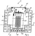
- the Fig. 1 shows a schematic cross-sectional view along the section line AA according to Fig. 4 an assembly and repair device 1 for vehicles according to a first embodiment of the invention, which has a usable in a bottom recess 3 cassette 5 made of steel or the like corrosion-resistant material.
- the cassette 5 has two longitudinal side walls 7 and 9 and a bottom 11.
- the longitudinal side walls 9 and 11 each have an inner wall 13 and an outer wall 15, which enclose between them a cavity 17 into which a hardenable filling material 19 is introduced.
- the Fig. 1 shows a front view of a partition wall 21, which limits a collecting space for receiving at least one collecting container for liquid hazardous goods, such as waste oil or fresh oil. Also fresh oils are in the present case under the term "liquid dangerous goods" taken.
- the partition wall 21 is preferably formed of metal, in particular as a separating plate and may have a thickness of about 3 - 4 mm or more.
- the partition wall 21 is preferably welded to the inner walls 13 and the bottom 11 of the cassette 5. The Partition 21 thus separates the plenum from the rest of the interior of the cassette 5.
- the partition wall 21 further comprises two openings 23 and 25, which for receiving in the Fig. 1 Serving fluid lines, not shown, which are in fluid communication with the reservoir.
- a waste oil drained from a vehicle can be guided into the collecting space and thus into the collecting container via the fluid lines and the openings 23 and 25, or fresh oil can be removed from the collecting container and the collecting space into the remaining interior of the cassette 5 and further on a vehicle arranged above the assembly and repair device 1 are guided.
- the fluid lines may also be in fluid communication with a fluid delivery trough, not shown in the figures, which may be arranged in particular in the region of the inner wall 13. If the sump is full and a corresponding level signal is output, the automatic shutdown of a fluid delivery pump, the oil or the like. transported to the waste oil tank. In the fluid conveying trough, fluid that is no longer to be taken up by the collecting container can then be temporarily stored until the collecting container has been properly emptied.
- the openings 23 and 25 are preferably provided with a refractory material, in particular refractory foam with a fire protection foam around the fluid lines around.
- the Fig. 2 shows a schematic cross-sectional view along the section line BB according to Fig. 4 an assembly and repair device 1, which shows a front view of a collecting space 29 and a collecting container 31 arranged therein.
- the assembly and repair device 1 has a displaceably mounted cover 33, which can be removed if the collecting container 31, for example for the purpose of pumping off used oil, must be accessed.
- the cover 33 may be part of the standard pit cover or separately formed be.
- the partition wall 21 is in the Fig. 2 not shown.
- the collecting space 29 is limited in the present embodiment on one side by a front side wall 35 of the cassette 5.
- the collecting space 29 is delimited by two partitions 21 from the rest of the interior of the cassette 5.
- the collecting space 29 is thus limited in regions by the two longitudinal side walls 7 and 9, by an end wall 35 and the partition 21.
- the collecting container 31 is arranged in the collecting space 29 in a recess 37 which extends below the accessible floor level E of the cassette 5. Further, the sump 31 may be bolted to the floor to avoid buoyancy of the container in the event of leakage.
- an opening 39 may be provided, which may be connected via a corresponding line to the collecting container 31 in order to realize a tank ventilation.
- the collecting container must have additional safety precautions for explosion protection, groundwater protection and the like.
- the collecting containers have a double-walled jacket whose cavity is filled with a leak-indicating liquid.
- a filling funnel For filling liquid in the collecting container, a filling funnel must be provided, which communicates with the interior of the container via a filler neck.
- the distance between the outer shell and the inner shell of the collecting container 31 should be selected so that in the case of leakage of the inner container of the cavity between the outer shell and the inner shell can accommodate up to 90% of the filling of the inner container.
- the collecting container also preferably has a fill level indicator and a pressure monitor, which can output a warning signal in the event of a leak of the collecting container 31.
- the collecting container 31 also has pallet feet 41, so that if necessary several collecting containers can be stacked on top of each other and the containers nevertheless remain accessible for pumping out liquid dangerous goods.
- the Fig. 3 shows a longitudinal section through a cassette 5. Good to see there in particular the outer wall 47 of the collecting container 31.
- the recess of the collecting chamber 29 may be in communication with a drainage device 45, which is in fluid communication with a sump of the assembly and repair device 1. Otherwise the collecting space must be hermetically sealed off from the environment in order to avoid an explosion hazard.
- the Fig. 4 shows a plan view of an assembly and repair device 1 in the region of the collecting space 29. Die Fig. 4 makes it clear that the collecting container 31 almost completely fills the collecting space 29. As already indicated above, it is not necessary to maintain a certain minimum distance between the inner wall 13 of the cassette 5 and the outer wall 47 of the collecting container 31 due to the double-walled design of the assembly and repair device 1. In this way it is possible to insert a standard collection container in a cassette, which need not be made wider than conventional cassettes. This is especially important for road transport of prefabricated assembly pits.
- the collecting container 31 has an opening 49, via which a tank truck, in particular by means of a hose or the like, can pump out liquid dangerous goods from the collecting container 31 or can fill fresh oil into a collecting container 31.
- a collecting space for receiving a dangerous goods container (collecting container) in a mounting and repair pit according to the present invention is also particularly advantageous because the disposal of the contents of the collecting container can easily be done in a tanker, which is parked on the mounting pit.
- the pit acts here advantageously as a ground-secured area of a Tankwagenhellstelle. When disposing of the dangerous goods in the tank truck, make sure that the suction hose line is always routed over the pit.
- the free space determination and the filling monitoring are carried out in the suction operation of the tanker by the driver who is a filler in the sense of the ADR (Accord europeen relatif au transport international of marchandises Dangerates par route or European Convention on the International Carriage of Dangerous Goods by Road). It is understood that the tanker must be approved according to ADR must have an overfill, which automatically closes the bottom valve of the tanker tank at maximum allowable level. This, too, is a decisive advantage of the invention over locally separated waste oil storerooms. It is understood that for filling or emptying of the collecting container 31, the cover 33 must be removed from the collecting space 29. For example, the cover 33 can be automatically displaced into a corresponding storage space for this purpose. This is particularly possible in a simple manner, when the cover 33 is formed like a blind or rigid. The cover 33 is also preferably designed to be overridden and provided with an anti-slip coating.
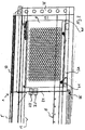
- the Fig. 5 and Fig. 6 show a further embodiment of the invention, in which the collecting space 29 and the collecting container 31 arranged therein are arranged outside the inner space 51 of the cassette 5.
- the separated collecting space 29 thus forms an extension of the cassette 5.
- the collecting space 29 directly adjoins the longitudinal side wall 9, which thus forms not only the longitudinal side wall 9 of the cassette 5, but also the longitudinal side wall of the collecting space 29.
- the cassette 5 and the collecting space 29 thus share a common wall.
- the same can also apply if the collecting space 29 in a further embodiment of the invention adjoins an end wall of the cassette 5.
- the remaining free longitudinal side wall 53 and the end side walls 55 and 57 of the collecting space 29 are preferably also like the walls of the cassette 5 double-walled with an intermediate cavity 17 for receiving a filling material.
- a supply channel 57 for supplying waste oil o.
- the like In the collecting container 31, wherein the supply channel is foamed with a refractory material.
- the supply channel 57 is introduced into the longitudinal side wall 9 and passes through this. In the same way it is also possible to place electrical lines in the plenum 29.
- the supply channel 57 can be connected via corresponding hoses / tubes to a fluid delivery device (pump) and to the above-described conveyor trough.
- the collecting space 29 also has a ventilation device 61, which is introduced in the form of a pipe (exhaust pipe) in the longitudinal side wall 9 and this passes through such that a fluid connection between the collecting space 29 and a vent channel of the cassette 5 results.
- the collecting container 31 may be connected via a corresponding pipe 65 with the venting device 61, or at least end in the vicinity thereof. From the venting device 61, the gases escaping from the collecting container 31 are conducted into the conventional forced venting system of the cassette 5.
- the Fig. 6 makes it clear that the exhaust pipe arranged in a lower, near-ground area, in particular in the lower third of the plenum 29 is. Since the gases present in the collecting space are usually heavier than air, they fall downwards and can be discharged there through the ventilation channel into the forced ventilation of the cassette 5.
- a fluid sensor 67 is still provided in the collecting space 29, which, seen in a height direction h, is arranged in a region below the ventilation device 61.
- the fluid sensor 67 may, for example, have a float which, in the event of fluid accumulation in the bottom area of the collecting container, triggers an alarm and effects an immediate shutdown of any oil delivery in progress in the collecting container 31.
- the maximum height h of a fluid level in the plenum 29 at which an alarm signal is triggered may vary depending on the height of the vent 61. It is crucial that the fluid sensor 67 seen in the height direction h, below the vent 61 can detect a fluid, so that no fluid can penetrate into the vent channel. If the venting device 61 is located, for example, at a height of 10 cm above the bottom, the fluid sensor 67 triggers an alarm or a stop signal preferably at a fluid level in the collecting chamber 29 of 5 cm.
- the fluid sensor 67 and the alarm device realized thereby thus constitutes a further protective measure which substantially increases the operational safety of the assembly and repair device according to the invention.
- the fluid sensor cooperates with a closable drainage device 69 which, when the fluid sensor 67 is triggered, makes it possible to inspect the fluid located in the collecting space 29.
- the dewatering device 69 is preferably designed in the form of a drainage channel, which passes through the longitudinal side wall 9 as well as the venting device 61 and thus creates a fluid connection to the cassette 5.
- the drainage channel is closed at its cassette end 63 with a stopcock and can be opened by an operator if necessary.
- the cassette-side end 63 preferably opens below the accessible floor level E into the interior 51 of the cassette 5.
- the dewatering device 69 of the collecting chamber 29 is preferably located in the vertical direction h, below the venting device 61, since a fluid present in the collecting space 29 in the event of a malfunction not even to reach the vent 61.
- the fluid sensor 67 detects a fluid at the bottom of the plenum
- the oil supply to the reservoir 31 is turned off and generates a corresponding visual and / or audible warning signal.
- An operator may then open the stopcock of the dehydrator 69 to determine the type of fluid in the plenum. If it is water, so it can be drained in just about the drainage 69 in the conventional water disposal of the cassette 5 (pump sump).
- the drainage device is preferably arranged at the low point of the collecting space.
- the drainage channel may preferably be inclined starting from the collecting space 29 to the inner space 51 of the cassette 5, so that a natural gradient is created, which allows a substantial emptying of the collecting space 29.
- the present invention advantageously creates an assembly and repair facility that allows storage of liquid hazardous goods accumulating in a workshop directly at the point of removal, namely in the assembly pit.
- a special storage room and corresponding underground oil supply lines are therefore not required.
Description
Die Erfindung betrifft eine Montage- und Reparatureinrichtung für Fahrzeuge, insbesondere Bau- und Nutzfahrzeuge gemäß dem Oberbegriff des Anspruchs 1.The invention relates to an assembly and repair device for vehicles, in particular construction and commercial vehicles according to the preamble of claim 1.
Montage- und Reparatureinrichtungen der hier angesprochenen Art sind beispielsweise aus der
Aufgabe der vorliegenden Erfindung ist es daher, eine Montage- und Reparatureinrichtung zu schaffen, die eine kostengünstige und einfach zu realisierende Alternative für die Entnahme und Lagerung von flüssigem Gefahrgut, insbesondere in Werkstätten schafft, insbesondere eine Alternative, die sich durch erhöhte Sicherheit vor Umweltverschmutzung auszeichnet sowie den Bewegungsraum innerhalb der Montagegrube nicht einschränkt.Object of the present invention is therefore to provide an assembly and repair facility, which creates a cost-effective and easy to implement alternative for the removal and storage of liquid hazardous goods, especially in workshops, especially an alternative that is characterized by increased safety from environmental pollution as well as the movement space within the mounting pit does not restrict.
Zur Lösung der oben genannten Aufgabe wird eine Montage- und Reparatureinrichtung mit den Merkmalen des Anspruchs 1 vorgeschlagen. Die Montage- und Reparatureinrichtung dient für Fahrzeuge, insbesondere Bau- und Nutzfahrzeuge und umfasst eine in eine Bodenausnehmung einsetzbare ein- oder mehrteilige Kassette aus Stahl oder dergleichen korrosionsbeständigem Material mit einem Innenraum, zwei Längsseitenwänden, endseitig angeordneten Stirnseitenwänden und einem Boden, wobei zumindest die Seitenwände jeweils eine Innenwandung und eine im Abstand dazu angeordnete Außenwandung aufweisen, die einen Hohlraum, insbesondere für die Aufnahme von einem aushärtbaren Füllmaterial begrenzen. Die Montage- und Reparatureinrichtung zeichnet sich dadurch aus, dass die Kassette einen abgetrennten Sammelraum zur Aufnahme mindestens eines Sammelbehälters für flüssiges Gefahrgut aufweist, wobei dieser Sammelraum hermetisch abgeriegelt und als seitliche Erweiterung der die Montageeinrichtung begrenzenden Kassette ausgebildet ist.To solve the above object, an assembly and repair device with the features of claim 1 is proposed. The assembly and repair device is used for vehicles, especially construction and commercial vehicles and includes a usable in a Bodenausnehmung single or multi-part cassette made of steel or the like corrosion-resistant material with an interior, two longitudinal side walls, end side end walls and a bottom, wherein at least the side walls each having an inner wall and an outer wall spaced therefrom defining a cavity, in particular for receiving a curable filler. The assembly and repair device is characterized in that the cassette has a separate collecting space for receiving at least one collecting container for liquid dangerous goods, said collecting space hermetically sealed off and formed as a lateral extension of the mounting device limiting cassette.
Ein wesentlicher Punkt der Erfindung liegt somit darin, dass die erfindungsgemäße Montage- und Reparatureinrichtung platzsparend ausgebildet ist, da sie keinen separaten Lagerraum benötigt. Daher sind auch keine aufwändig zu verlegenden unterirdischen Leitungen notwendig, um beispielsweise Altöl oder sonstiges flüssiges Gefahrgut eines Fahrzeugs oder einer Maschine aufzunehmen oder auch um einem Fahrzeug Frischöl zuzuführen. Durch den erfindungsgemäßen in die Montage- und Reparaturgrube integrierten Sammelraum zur Aufnahme des Sammelbehälters kann ein flüssiges Gefahrgut unmittelbar in der Reparaturgrube, d.h. am Ort der Entnahme gelagert und durch ein Tankfahrzeug entsorgt werden. Beispielsweise kann ein Fahrzeug zum Entsorgen von Getriebeöl o. dgl. über der Grube positioniert und ein flexibles Rinnensystem unter die jeweilige Entsorgungsöffnung des Fahrzeugs positioniert werden. Das Öl kann dann aus dem Fahrzeug über das (offene) Rinnensystem durch ein natürliches Gefälle und ggf. unter Einsatz von mindestens einer füllstandsabhängig arbeitenden Pumpe über ein Rohr-/Schlauchsystem zu dem Sammelbehälter (Altöltank) in dem Sammelraum geleitet werden. Besonders zu beachten ist bei Sammelbehältern für flüssiges Gefahrgut die Einhaltung von Brandschutzmaßnahmen. Üblicherweise ist um die Außenhülle des Sammelbehälters herum ein Freiraum von mindestens 40 cm einzuhalten. Dadurch, dass die erfindungsgemäße Montage- und Reparatureinrichtung doppelwandig, d.h. mit einer Innenwandung und einer Außenwandung, die in einem Abstand zueinander angeordnet sind, ausgebildet ist, entfällt dieses Erfordernis gänzlich. Der Sammelraum zur Aufnahme des Sammelbehälters erfordert daher keine Spezialmaße, sondern kann in die in der bekannten Weise bemessenen Montage- und Reparatureinrichtungen implementiert werden. Während der Lagerraum für Altöl mindestens eine Feuerwiderstandsklasse F30 aufweisen muss, fällt die doppelwandig ausgebildete Montagegrube sogar in die Feuerwiderstandsklasse F90 und bietet damit ein Mehrfaches der geforderten Sicherheit eines Altöl-Lagerraums. Unter die Erfindung fällt dabei eine Integration des Sammelraums in die Kassette ebenso wie eine Anordnung des Sammelraums als seitliche Erweiterung der Kassette.An essential point of the invention is therefore that the assembly and repair device according to the invention is designed to save space, since it does not require a separate storage room. Therefore, no costly to be laid underground lines are necessary to record, for example, waste oil or other liquid dangerous goods of a vehicle or a machine or to supply fresh oil to a vehicle. The inventive integrated into the assembly and repair pit collecting space for receiving the collection container, a liquid dangerous goods directly in the repair pit, ie stored at the place of removal and disposed of by a tanker. For example, a vehicle for disposing of transmission oil or the like may be positioned over the pit and a flexible gutter system may be positioned below the respective disposal port of the vehicle. The oil can then be passed from the vehicle via the (open) channel system by a natural gradient and possibly using at least one level-dependent pump via a pipe / hose system to the sump (waste oil tank) in the plenum. Particular attention should be paid to the observance of fire protection measures for collecting containers for liquid dangerous goods. Usually, a free space of at least 40 cm must be kept around the outer shell of the collecting container. Characterized in that the assembly and repair device according to the invention double-walled, ie with an inner wall and an outer wall, which are arranged at a distance from each other, is omitted this requirement entirely. The collection space for receiving the collection therefore requires no special dimensions, but can be implemented in the dimensioned in the known manner mounting and repair facilities. While the storage room for waste oil must have at least one fire resistance class F30, the double-walled installation pit even falls into the fire resistance class F90 and thus offers several times the required safety of a waste oil storage room. The invention includes an integration of the collecting space into the cassette as well as an arrangement of the collecting space as a lateral extension of the cassette.
Besonders vorteilhaft ist es, wenn ein Sammelbehälter zur Aufnahme von flüssigem Gefahrgut fest in dem Sammelraum installiert ist. Die Kassette wird dann herstellerseitig mit dem Sammelbehälter bestückt und unmittelbar vor Ort in eine Bodenausnehmung eingesetzt. Der Sammelbehälter kann zur Aufnahme von Altöl oder Frischöl ausgebildet sein. Denkbar ist auch die Anordnung von zwei oder mehr Sammelbehältern in einem Sammelraum einer Kassette, wobei beispielsweise ein Sammelbehälter zur Aufnahme von Altöl und ein weiterer Sammelbehälter zur Aufnahme von Frischöl dienen kann. Dabei kann ein Sammelbehälter ein Fassungsvermögen von beispielsweise 2000 Litern aufweisen. Da es grundsätzlich verboten ist, Altöle mit anderen Abfällen zu vermischen, muss eine getrennte Lagerung erfolgen. Der Sammelbehälter ist darüber hinaus vorzugsweise doppelwandig derart ausgebildet, dass beide Wandungen aus Stahl ausgebildet sind. Der Sammelbehälter ist darüber hinaus vorzugsweise quaderförmig, insbesondere kubisch, ausgebildet und kann auf diese Weise den Sammelraum besonders gut ausnutzen. Je nach Gefährdungsstufe des aufzunehmenden Gefahrguts können die Anforderungen an den Sammelbehälter unterschiedlich sein.It is particularly advantageous if a collecting container for receiving liquid dangerous goods is permanently installed in the collecting space. The cassette is then fitted on the manufacturer side with the collecting container and used directly on site in a bottom recess. The sump can be designed to hold used oil or fresh oil. Also conceivable is the arrangement of two or more collecting containers in a collecting space of a cassette, wherein, for example, a collecting container for receiving waste oil and another collecting container for receiving fresh oil can serve. In this case, a collection container can have a capacity of, for example, 2000 liters. Since it is generally forbidden to mix waste oils with other waste, separate storage must be carried out. The collecting container is also preferably double-walled in such a way that both walls are formed of steel. The collecting container is also preferably cuboid, in particular cubic, formed and can in this way take advantage of the collection space particularly well. Depending on the risk level of the hazardous substance to be absorbed, the requirements for the collecting container may be different.
Der Sammelraum ist vorzugsweise durch mindestens eine Trennwand, insbesondere durch ein Trennblech von dem übrigen Innenraum der Kassette getrennt. Der Sammelraum kann auch von einer Seitenwand der Kassette begrenzt werden, so dass in diesem Fall nur eine Trennwand auf der der Seitenwand der Kassette gegenüberliegende Seite zur Begrenzung des Sammelraums notwendig ist. Die Trennwand ist vorzugsweise mit der Innenwand und mit dem Boden der Kassette verschweißt. Sie kann ferner auf ihrer dem Sammelbehälter zugewandten Seite mit einem Brandschutzlack versehen sein. Die Trennwand weist vorzugsweise wenigstens eine Öffnung zur Aufnahme einer mit dem Sammelbehälter in Verbindung stehenden Fluidleitung auf. Über diese mindestens eine Fluidleitung kann beispielsweise Altöl in den Sammelbehälter geleitet werden. Als Brandschutzmaßnahme kann die Öffnung mit einem feuerfesten Material, insbesondere mit einem Brandschutzschaum abgedichtet sein, nachdem die Fluidleitung in die Öffnung eingeführt wurde. Der Sammelraum muss zur Vermeidung einer Explosionsgefahr hermetisch abgeriegelt sein. Der Sammelraum kann über mindestens eine Entwässerungseinrichtung verfügen. Damit ein Gefahrgut, insbesondere Altöl von einem dafür vorgesehenen Tankwagen aus dem Sammelbehälter abgepumpt werden kann, weist die Kassette im Bereich des Sammelraums vorzugsweise eine verlagerbare Abdeckung auf, die einen Zugang zu dem Sammelbehälter ermöglicht. Die Abdeckung ist aus Brandschutzgründen vorzugsweise aus Stahl oder einem ähnlichen Material ausgebildet.The collecting space is preferably separated from the remaining interior of the cassette by at least one dividing wall, in particular by a separating plate. The collecting space can also be limited by a side wall of the cassette, so that in this case only a partition on the side wall of the cassette opposite side to limit the collection space is necessary. The partition is preferably welded to the inner wall and to the bottom of the cassette. It can also be provided on its side facing the sump with a fire-proof paint. The partition wall preferably has at least one opening for receiving a with the collecting container in Connecting fluid line. For example, waste oil can be conducted into the collecting container via this at least one fluid line. As a fire protection measure, the opening can be sealed with a refractory material, in particular with a fire protection foam, after the fluid line has been introduced into the opening. The plenum must be hermetically sealed to prevent the risk of explosion. The collecting space may have at least one drainage device. So that a dangerous good, in particular used oil can be pumped from a designated tanker from the sump, the cassette in the region of the collection space preferably has a movable cover, which allows access to the sump. The cover is preferably made of steel or similar material for fire protection reasons.
Weiterhin kann die Montage- und Reparaturgrube vorteilhafterweise eine Entlüftungseinrichtung in dem Sammelraum aufweist, die insbesondere in einem unteren Drittel des Sammelraums angeordnet sein kann und eine Fluidverbindung zu dem (übrigen) Innenraum der Kassette darstellen kann.
Die Entlüftungseinrichtung kann dabei mit einer Zwangsentlüftungseinrichtung der Kassette verbunden sein. Weiterhin kann der Sammelraum einen Flüssigkeitssensor aufweisen, der vorzugsweise unterhalb der Entlüftungseinrichtung angeordnet ist. Der Fluidsensor bildet eine Alarmvorrichtung, die im Falle einer Fluidansammlung ein Warnsignal erzeugt, welches zum Abschalten einer Fluidzufuhr zu dem Sammelbehälter führt. Hierdurch ergibt sich eine zusätzliche Schutzmaßnahme der Erfindung. Weiterhin kann der Sammelraum einen verschließbaren Entwässerungskanal aufweisen, der vorzugsweise unterhalb der Entlüftungseinrichtung angeordnet ist und eine Fluidverbindung zwischen dem Sammelraum und einem Entwässerungssystem der Kassette herstellen kann.Furthermore, the assembly and repair pit can advantageously have a venting device in the collecting space, which can be arranged in particular in a lower third of the collecting space and can represent a fluid connection to the (remaining) interior of the cassette.
The venting device can be connected to a forced venting device of the cassette. Furthermore, the collecting space may comprise a liquid sensor, which is preferably arranged below the venting device. The fluid sensor forms an alarm device, which generates a warning signal in the event of fluid accumulation, which leads to switching off a fluid supply to the collecting container. This results in an additional protective measure of the invention. Furthermore, the collecting space can have a closable drainage channel, which is preferably arranged below the ventilation device and can establish a fluid connection between the collecting space and a drainage system of the cassette.
Die Erfindung wird im Folgenden anhand der Zeichnung näher erläutert. Es zeigen:
- Fig. 1
- Eine schematische Querschnittdarstellung einer in eine Bodenausnehmung eingesetzte Kassette mit einem integrierten Sammelraum zur Aufnahme mindestens eines Sammelbehälters entlang der Schnittlinie A-A gemäß einer ersten Ausführungsform der Erfindung;
- Fig. 2
- eine schematische Querschnittdarstellung durch den Sammelraum einer erfindungsgemäßen Montage- und Reparatureinrichtung mit einem darin angeordneten Sammelbehälter entlang der Schnittlinie B-B gemäß der ersten Ausführungsform der Erfindung;
- Fig. 3
- eine schematische Längsschnittdarstellung einer erfindungsgemäßen Montage- und Reparatureinrichtung mit einem Sammelraum und einem darin angeordneten Sammelbehälter gemäß der ersten Ausführungsform der Erfindung;
- Fig. 4
- eine schematische Draufsicht auf einen Sammelraum und einen darin angeordneten Sammelbehälter gemäß der ersten Ausführungsform der Erfindung;
- Fig. 5
- eine schematische Draufsicht auf eine Kassette mit seitlich angeordnetem Sammelraum nach einer weiteren Ausführungsform der Erfindung; und
- Fig. 6
- eine schematische Querschnittdarstellung einer Kassette mit seitlich angeordnetem Sammelraum nach der weiteren Ausführungsform der Erfindung.
- Fig. 1
- A schematic cross-sectional view of an inserted into a bottom recess cassette with an integrated plenum for receiving at least one collecting container along the section line AA according to a first embodiment of the invention;
- Fig. 2
- a schematic cross-sectional view through the plenum of an assembly and repair device according to the invention with a collecting container arranged therein along the section line BB according to the first embodiment of the invention;
- Fig. 3
- a schematic longitudinal sectional view of an assembly and repair device according to the invention with a collecting space and a collecting container arranged therein according to the first embodiment of the invention;
- Fig. 4
- a schematic plan view of a collecting space and a collecting container arranged therein according to the first embodiment of the invention;
- Fig. 5
- a schematic plan view of a cassette with laterally arranged collecting space according to a further embodiment of the invention; and
- Fig. 6
- a schematic cross-sectional view of a cassette with laterally arranged collecting space according to the further embodiment of the invention.
Die
Die
Die Fluidleitungen können auch mit einer in den Figuren nicht gezeigten Fluidförderrinne in Fluidverbindung stehen, die insbesondere im Bereich der Innenwandung 13 angeordnet sein kann. Sofern der Sammelbehälter voll ist und ein entsprechendes Füllstandssignal ausgegeben wird, erfolgt die automatische Abschaltung einer Fluidförderpumpe, die das Öl o.dgl. in den Altöltank befördert. In der Fluidförderrinne kann dann von dem Sammelbehälter nicht mehr aufzunehmendes Fluid zwischengelagert werden, bis der Sammelbehälter sachgerecht entleert wurde. Wenn die Fluidleitungen in den Öffnungen 23 und 25 angeordnet sind, werden die Öffnungen 23 und 25 vorzugsweise mit einem feuerfesten Material versehen, insbesondere feuerfest mit einem Brandschutzschaum um die Fluidleitungen herum ausgeschäumt. Aufgrund der doppelwandigen Ausbildung der Montage- und Reparatureinrichtung 1 im Bereich der Seitenwände 7 und 9 kann auf die Anbringung einer Brandschutzplatte zur Verstärkung der Trennwand 21 verzichtet werden. Auf diese Weise kann der Sammelraum und insbesondere seine Abtrennung zu dem übrigen Innenraum der Kassette 5 besonders einfach mittels der Trennwand 21 realisiert werden, da keine weiteren Brandschutzmaßnahmen erforderlich sind.The fluid lines may also be in fluid communication with a fluid delivery trough, not shown in the figures, which may be arranged in particular in the region of the
Die
Der Sammelbehälter 31 ist in dem Sammelraum 29 in einer Vertiefung 37 angeordnet, die sich unterhalb der begehbaren Bodenebene E der Kassette 5 erstreckt. Ferner kann der Sammelbehälter 31 mit dem Boden verschraubt sein, um einen Auftrieb des Behälters im Leckagefall zu vermeiden. In der Stirnseitenwand 35 kann eine Öffnung 39 vorgesehen sein, die über eine entsprechende Leitung mit dem Sammelbehälter 31 verbunden sein kann, um eine Tankentlüftung zu realisieren. Je nach Gefahrenklasse des zu lagernden Gefahrguts muss der Sammelbehälter zusätzliche Sicherheitsvorkehrungen zum Explosionsschutz, Grundwasserschutz und dergleichen aufweisen. In der Regel weisen die Sammelbehälter einen doppelwandigen Mantel auf, dessen Hohlraum mit einer Leckanzeigeflüssigkeit gefüllt ist. Zum Einfüllen von Flüssigkeit in den Sammelbehälter muss ein Einfülltrichter vorgesehen sein, der über einen Füllstutzen mit dem Inneren des Behälters in Verbindung steht. Der Abstand zwischen der Außenhülle und der Innenhülle des Sammelbehälters 31 sollte so gewählt sein, dass im Leckagefall des Innenbehälters der Hohlraum zwischen der Außenhülle und der Innenhülle bis zu 90% der Füllung des Innenbehälters aufnehmen kann. Der Sammelbehälter weist ferner vorzugsweise eine Füllstandsanzeige und einen Druckwächter auf, der im Falle eines Lecks des Sammelbehälters 31 ein Warnsignal ausgeben kann. Der Sammelbehälter 31 weist darüber hinaus Palettenfüße 41 auf, so dass bei Bedarf mehrere Sammelbehälter übereinander stapelbar sind und die Behälter dennoch zum Abpumpen von flüssigem Gefahrengut zugänglich bleiben.The collecting
Die
Die
Der Sammelbehälter 31 weist eine Öffnung 49 auf, über die ein Tankwagen, insbesondere mittels eines Schlauchs oder dergleichen, flüssiges Gefahrgut aus dem Sammelbehälter 31 abpumpen kann oder Frischöl in einen Sammelbehälter 31 einfüllen kann. Die Integration eines Sammelraums zur Aufnahme eines Gefahrgut-Behälters (Sammelbehälter) in eine Montage- und Reparaturgrube gemäß der vorliegenden Erfindung ist auch deshalb besonders vorteilhaft, weil die Entsorgung des Inhalts des Sammelbehälters einfach in ein Tankfahrzeug erfolgen kann, welches auf der Montagegrube abgestellt ist. Die Grube wirkt hierbei in vorteilhafter Weise als bodenabgesicherter Bereich einer Tankwagenfüllstelle. Bei der Entsorgung des Gefahrguts in den Tankwagen ist darauf zu achten, dass die Führung der Saugschlauchleitung immer über der Grube erfolgt. Die Freiraumermittlung und die Befüllungsüberwachung erfolgen im Saugbetrieb des Tankfahrzeugs durch den Fahrzeugführer, der Befüller im Sinne des ADR (Accord europeen relatif au transport international des marchandises Dangereuses par Route bzw. Europäisches Übereinkommen über die internationale Beförderung gefährlicher Güter auf der Straße) ist. Es versteht sich, dass das Tankfahrzeug nach ADR zugelassen sein über eine Überfüllsicherung verfügen muss, welche das Bodenventil des Tankwagen-Behälters bei maximal zulässigem Füllstand selbsttätig schließt. Auch dies ist ein entscheidender Vorteil der Erfindung gegenüber örtlich getrennt angeordneten Altöl-Lagerräumen. Es versteht sich, dass zum Befüllen oder Entleeren des Sammelbehälters 31 die Abdeckung 33 von dem Sammelraum 29 entfernt werden muss. Die Abdeckung 33 kann hierzu beispielsweise automatisch in einen entsprechenden Speicherraum verlagert werden. Dies ist insbesondere dann auf einfache Art und Weise möglich, wenn die Abdeckung 33 rolladenartig oder starr ausgebildet ist. Die Abdeckung 33 ist darüber hinaus vorzugsweise überfahrbar ausgebildet und mit einer Anti-Rutsch-Beschichtung versehen.The collecting
Die
Wie auch die Ausführungsform der Erfindung nach den
Der Sammelraum 29 weist darüber hinaus eine Entlüftungseinrichtung 61 auf, die in Form eines Rohrs (Abluftrohr) in die Längsseitenwand 9 eingebracht ist und diese derart durchgreift, dass eine Fluidverbindung zwischen dem Sammelraum 29 und einem Entlüftungskanal der Kassette 5 resultiert. Der Sammelbehälter 31 kann über eine entsprechende Rohrleitung 65 mit der Entlüftungseinrichtung 61 verbunden sein, oder zumindest in deren Nähe enden. Von der Entlüftungseinrichtung 61 aus werden die aus dem Sammelbehälter 31 entweichenden Gase in die herkömmliche Zwangsentlüftungsanlage der Kassette 5 geleitet.The collecting
Die
Weiterhin ist in dem Sammelraum 29 noch ein Fluidsensor 67 vorgesehen, der, in einer Höhenrichtung h gesehen, in einem Bereich unterhalb der Entlüftungseinrichtung 61 angeordnet ist. Der Fluidsensor 67 kann beispielsweise einen Schwimmer aufweisen, der im Fall einer Fluidansammlung im Bodenbereich des Sammelbehälters einen Alarm auslöst und ein sofortiges Abschalten einer ggf. im Gange befindlichen Ölförderung in den Sammelbehälter 31 bewirkt. Die maximale Höhe h eines Fluidfüllstandes in dem Sammelraum 29, bei der ein Alarmsignal ausgelöst wird, kann je nach der Höhe der Entlüftungseinrichtung 61 variieren. Entscheidend ist, dass der Fluidsensor 67 in der Höhenrichtung h gesehen, unterhalb der Entlüftungseinrichtung 61 ein Fluid detektieren kann, sodass kein Fluid in den Entlüftungskanal eindringen kann. Falls sich die Entlüftungseinrichtung 61 beispielsweise in einer Höhe von 10 cm oberhalb des Bodens befindet, löst der Fluidsensor 67 vorzugsweise bei einem Fluidfüllstand im Sammelraum 29 von 5 cm einen Alarm bzw. ein Stoppsignal aus.Furthermore, a
Der Fluidsensor 67 und die dadurch realisierte Alarmvorrichtung stellt somit eine weitere Schutzmaßnahme dar, welche die Betriebssicherheit der erfindungsgemäßen Montage- und Reparatureinrichtung wesentlichen erhöht. Im Übrigen wirkt der Fluidsensor mit einer verschließbaren Entwässerungseinrichtung 69 zusammen, die bei Auslösen des Fluidsensors 67 eine Inspektion des in dem Sammelraum 29 befindlichen Fluids ermöglicht. Die Entwässerungseinrichtung 69 ist vorzugsweise in Form eines Entwässerungskanals ausgebildet, der die Längsseitenwand 9 ebenso wie die Entlüftungseinrichtung 61 durchgreift und damit eine Fluidverbindung zu der Kassette 5 schafft. Der Entwässerungskanal ist an seinem kassettenseitigen Ende 63 mit einem Absperrhahn verschlossen und kann bei Bedarf durch eine Bedienperson geöffnet werden. Das kassettenseitige Ende 63 mündet vorzugsweise unterhalb der begehbaren Bodenebene E in den Innenraum 51 der Kassette 5. Zweckmäßigerweise ist die Entwässerungseinrichtung 69 des Sammelraums 29 vorzugsweise in der Höhenrichtung h gesehen, unterhalb der Entlüftungseinrichtung 61 angeordnet, da ein im Störfall in dem Sammelraum 29 vorhandenes Fluid gar nicht erst bis zu der Entlüftungseinrichtung 61 gelangen soll.The
Sofern ein Störfall vorliegt und der Fluidsensor 67 ein Fluid am Boden des Sammelraums detektiert, wird die Ölzufuhr zu dem Sammelbehälter 31 abgeschaltet und ein entsprechendes optisches und/oder akustisches Warnsignal erzeugt. Eine Bedienperson kann dann den Absperrhahn der Entwässerungseinrichtung 69 öffnen, um die Art des in dem Sammelraum befindlichen Fluids festzustellen. Handelt es sich um Wasser, so kann es in einfach über die Entwässerungseinrichtung 69 in die herkömmliche Wasserentsorgung der Kassette 5 (Pumpensumpf) abgelassen werden. Um in diesem Falls so viel Wasser wie möglich aus dem Sammelraum ablassen zu können, ist die Entwässerungseinrichtung vorzugweise am Tiefpunkt des Sammelraums angeordnet. Ferner kann der Entwässerungskanal vorzugsweise ausgehend von dem Sammelraum 29 zu dem Innenraum 51 der Kassette 5 hin geneigt sein, sodass ein natürliches Gefälle entsteht, welches eine weitgehende Entleerung des Sammelraums 29 ermöglicht.If an accident occurs and the
Handelt es sich bei dem im Sammelraum 29 befindlichen Fluid hingegen um Öl o. dgl. Gefahrgut, muss die Abdeckung 33 geöffnet und das Gefahrgut professionell abgepumpt werden. Ein Eindringen eines Fluids in den Entlüftungskanal ist somit durch die Alarmvorrichtung in jedem Fall ausgeschlossen. Es versteht sich, dass die sensorielle Sicherheitsüberwachung zur Detektion eines Fluids in dem Sammelraum 29 auch in der in den
Insgesamt zeigt sich, dass die vorliegende Erfindung in vorteilhafter Weise eine Montage- und Reparatureinrichtung schafft, die eine Lagerung von in einer Werkstatt anfallendem flüssigem Gefahrgut unmittelbar am Ort der Entnahme, nämlich in der Montagegrube ermöglicht. Ein spezieller Lagerraum und entsprechende unterirdische Ölförderleitungen sind daher nicht erforderlich. Durch die Anordnung des Sammelraums in/an der doppelwandigen Kassette sind darüber hinaus die erforderlichen Brandschutzmaßnahmen für den Sammelbehälter 31 nicht nur erfüllt, sondern übertreffen diese bei Weitem. Eine zusätzliche Brandschutzplatte ist insbesondere im Bereich der Trennwand 21 nicht notwendig. Auch muss kein Mindestabstand zwischen der Außenwand 47 des Sammelbehälters 31 und der Innenwandung 13, der Stirnseitenwand 35 und der Trennwand 21 der Kassette 5 eingehalten werden, wodurch der Sammelraum keine erheblichen baulichen Veränderungen der Kassette erfordert.Overall, it is found that the present invention advantageously creates an assembly and repair facility that allows storage of liquid hazardous goods accumulating in a workshop directly at the point of removal, namely in the assembly pit. A special storage room and corresponding underground oil supply lines are therefore not required. By arranging the collecting space in / on the double-walled cassette beyond the required fire protection measures for the collecting
Denkbar ist es grundsätzlich auch, mehr als einen Sammelbehälter in dem Sammelraum 29 vorzusehen. Insbesondere können diese in einer Längsrichtung L der Kassette 5 hintereinander angeordnet sein, die wiederum in einem gemeinsamen Sammelraum angeordnet sind. Das Fassungsvermögen der Sammelbehälter kann ebenfalls unterschiedlich sein. Denkbar ist es beispielsweise, mehrere Sammelbehälter mit identischen oder verschiedenen Fassungsvermögen in dem Sammelraum 29 anzuordnen.It is also conceivable, in principle, to provide more than one collecting container in the collecting
- 11
- Montage- und ReparaturgrubeAssembly and repair pit
- 33
- Bodenausnehmungbottom recess
- 55
- Kassettecassette
- 77
- LängsseitenwandLongitudinal side wall
- 99
- LängsseitenwandLongitudinal side wall
- 1111
- Bodenground
- 1313
- Innenwandunginner wall
- 1515
- Außenwandungouter wall
- 1717
- Hohlraumcavity
- 1919
- Füllmaterialfilling material
- 2121
- Trennwandpartition wall
- 2323
- Öffnungopening
- 2525
- Öffnungopening
- 2929
- Sammelraumplenum
- 3131
- SammelbehälterClippings
- 3333
- Abdeckungcover
- 3535
- StirnseitenwandEnd wall
- 3737
- Vertiefungdeepening
- 3939
- Öffnungopening
- 4141
- Palettenfüßepallet feet
- 4545
- Entwässerungseinrichtungdehydrator
- 4747
- Außenwandungouter wall
- 4949
- Öffnungopening
- 5151
- Innenrauminner space
- 5353
- LängsseitenwandLongitudinal side wall
- 5555
- StirnseitenwandEnd wall
- 5757
- StirnseitenwandEnd wall
- 5959
- Zuführkanalfeed
- 6161
- Entlüftungseinrichtungvent
- 6363
- Kassettenseitiges EndeCassette-side end
- 6565
- Rohrleitungpipeline
- 6767
- Fluidsensorfluid sensor
- 6969
- Entwässerungseinrichtungdehydrator
- Ee
- Bodenebeneground level
- LL
- Längsrichtunglongitudinal direction
- hH
- Höhenrichtungheight direction
Claims (17)
- An assembly and repair device (1) for vehicles, in particular construction vehicles and commercial vehicles, comprising a single part or multi part cassette (5) made of steel or a similar corrosion-resistant material having an interior space (51), which is insertable into a recess (3) in the floor, two longitudinal sidewalls (7, 9), end-face walls (35), which are arranged at the ends, and a base (11, E), wherein at least the sidewalls (7, 9, 35) each comprising an inner wall (13) and an outer wall (15) spaced apart therefrom, defining a cavity (17) which can be filled with a curable filling (19),
characterized in that
the cassette (5) comprises a separated collection chamber (29) for retrieving of at least one collection case (31) for liquid hazardous material, wherein said collection chamber (29) is hermetically sealed, and wherein the separated collection chamber (29) is formed as a longitudinal extension of the cassette (5) and abuts against a longitudinal sidewall (9) or end-face wall (35) thereof, in particular. - The assembly and repair device according to claim 1,
characterized in that
said at least one collection case (31) is fixedly installed in the collection chamber (29). - The assembly and repair device according to claim 2,
characterized in that
said at least one collection case (31) is formed for receiving of waste oil or fresh oil. - The assembly and repair device according to claim 2 or 3,
characterized in that
said at least one collection case (31) is formed double-walled from steel and is formed cube-shaped. - The assembly and repair device according to one of the preceding claims,
characterized in that
the collection chamber (29) is separated from the spare interior space of the cassette (5) by at least one separating wall (21), in particular by means of a separating plate. - The assembly and repair device according to claim 5,
characterized in that
the at least one separating wall (21) is welded to the inner wall and the base (E) of the cassette (5), and wherein, in particular the side facing to the collection case (31), is provided with a fire protection finish. - The assembly and repair device according to one of claims 5 to 6,
characterized in that
the at least one separating wall (21) comprises at least one opening (23, 25) for receiving of a fluid conduit coupled to the collection case (31). - The assembly and repair device according to claim 7,
characterized in that
the at least one opening (23, 25) is provided with a fire resistant material, in particular a fire protection foam. - The assembly and repair device according to one of the preceding claims,
characterized in that
the collection chamber (29) comprises at least one dewatering means (45). - The assembly and repair device according to one of the preceding claims,
characterized in that
the collection chamber (29) is confined by means of an end-face wall (35) of the cassette (5). - The assembly and repair device according to one of the preceding claims,
characterized in that
the cassette (5) comprises a displaceable cover (33) in the area of the collection chamber (29). - The assembly and repair device according to one of the preceding claims,
characterized in that
the separated collection chamber (29) and the cassette (5) comprise at least one common longitudinal sidewall or end-face wall. - The assembly and repair device according to one of the preceding claims,
characterized in that
the separated collection chamber (29) comprises a venting means (61), which is arranged in a lower third of the collection chamber (29), in particular, and provides a fluid connection to the (spare) inner chamber of the cassette (5). - The assembly and repair device according to one of the preceding claims, characterized in that
the venting means (61) is connected to a forced venting means of the cassette (5). - The assembly and repair device according to one of the preceding claims,
characterized in that
the collection chamber (29) comprises a fluid sensor (67), which is arranged below the venting means (61), in particular. - The assembly and repair device according to one of the preceding claims,
characterized in that
the collection chamber (29) comprises a closable dewatering means (69), which is arranged below the venting means (61), in particular, and which is adapted to provide a fluid connection between the collection chamber (29) and a dewatering system of the cassette (5). - The assembly and repair device according to one of the preceding claims,
characterized in that
the assembly and repair device is formed as a tank truck filling place and comprises a ground protected area thereof.
Applications Claiming Priority (1)
| Application Number | Priority Date | Filing Date | Title |
|---|---|---|---|
| DE102012110430.1A DE102012110430A1 (en) | 2012-10-31 | 2012-10-31 | Assembly and repair facility |
Publications (2)
| Publication Number | Publication Date |
|---|---|
| EP2728090A1 EP2728090A1 (en) | 2014-05-07 |
| EP2728090B1 true EP2728090B1 (en) | 2016-03-23 |
Family
ID=48288916
Family Applications (1)
| Application Number | Title | Priority Date | Filing Date |
|---|---|---|---|
| EP13166674.5A Active EP2728090B1 (en) | 2012-10-31 | 2013-05-06 | Assembly and repair device |
Country Status (3)
| Country | Link |
|---|---|
| EP (1) | EP2728090B1 (en) |
| DE (1) | DE102012110430A1 (en) |
| DK (1) | DK2728090T3 (en) |
Families Citing this family (2)
| Publication number | Priority date | Publication date | Assignee | Title |
|---|---|---|---|---|
| DE202017101970U1 (en) * | 2017-04-04 | 2018-07-05 | Balzer GmbH & Co. KG | Assembly and repair pit with reinforcement bar for anchoring in a hall floor |
| DE102017112377A1 (en) | 2017-06-06 | 2018-12-06 | Balzer GmbH & Co. KG | Waste oil tank in mine |
Family Cites Families (7)
| Publication number | Priority date | Publication date | Assignee | Title |
|---|---|---|---|---|
| US3938621A (en) * | 1973-06-06 | 1976-02-17 | Rudolph Hafner | Vehicle servicing system |
| DE3937822A1 (en) * | 1989-11-14 | 1991-05-16 | Joerg Kreuzer | Parking place for container with metal waste and cutting fluids - has concrete, polymer coated pit with collecting hopper, tank and horizontal extension at upper edge below container |
| DE9320679U1 (en) * | 1993-05-26 | 1995-02-02 | Balzer Heide | Assembly and repair pit |
| US5613331A (en) * | 1994-12-29 | 1997-03-25 | Laganke; Timothy J. | Modular oil change and lubrication center for vehicles |
| DE29721907U1 (en) * | 1997-12-11 | 1998-04-02 | Huber Siegfried | Draining station for recycling old cars |
| DE202008003251U1 (en) | 2008-03-06 | 2008-08-28 | Hans Balzer Werkstatt- und Fahrzeugtechnik GmbH & Co. KG | Assembly and repair pit as well as system for the disposal of waste water in the area of assembly pits |
| DE102009012047A1 (en) | 2009-02-26 | 2010-09-02 | Hans Balzer | Assembly and repair facility |
-
2012
- 2012-10-31 DE DE102012110430.1A patent/DE102012110430A1/en not_active Withdrawn
-
2013
- 2013-05-06 EP EP13166674.5A patent/EP2728090B1/en active Active
- 2013-05-06 DK DK13166674.5T patent/DK2728090T3/en active
Also Published As
| Publication number | Publication date |
|---|---|
| DK2728090T3 (en) | 2016-07-04 |
| EP2728090A1 (en) | 2014-05-07 |
| DE102012110430A1 (en) | 2014-06-12 |
Similar Documents
| Publication | Publication Date | Title |
|---|---|---|
| EP2098662B1 (en) | Assembly and repair pit and system for draining waste water from assembly pits | |
| US20100206883A1 (en) | Fluid Container | |
| EP1247763B1 (en) | Container for water polluting liquids | |
| DE10139353B4 (en) | Changeable, completely prefabricated tank system | |
| EP2728090B1 (en) | Assembly and repair device | |
| EP4098870B1 (en) | Viscous material pump | |
| DE4420795A1 (en) | Mobile fuel dispensing system | |
| DE10050333B4 (en) | Transfer station for tank systems | |
| EP0285144B1 (en) | Mobile device for extracting harmful liquids | |
| DE102017113746B3 (en) | Mobile container for drinking water | |
| DE4429317A1 (en) | Device for collecting used fluid to be disposed of and/or for supplying new fluid | |
| DE102007012533A1 (en) | Mobile tank i.e. load tanker, for use in tank lorry, has chamber divided into two tank compartments by sound-proof wall, where compartments includes unit in vertex area of tank for unchangeably forming gas volume above liquid level in tank | |
| DE4309491C2 (en) | Underground tank truck with compressed air discharge | |
| AT520039A2 (en) | Waste oil tank in mine | |
| DE4431037B4 (en) | Liquid collection device with two-chamber collecting container | |
| EP3287316B1 (en) | Adapter for transforming a dump truck and dump truck | |
| DE10118169B4 (en) | Mobile petrol station | |
| DE102012213975A1 (en) | Rail vehicle with an internal tank | |
| DE202020106689U1 (en) | Protection arrangement and dangerous goods storage arrangement | |
| CH651271A5 (en) | Storage device with a container containing an environmentally hazardous liquid | |
| AT404577B (en) | LIQUID TANK FOR A VEHICLE, ESPECIALLY A MUNICIPAL VEHICLE | |
| DE102011052172A1 (en) | Delivery station i.e. filler point, for delivering petrol in canister of power saw, has tapping system connected with dry clutch part at its input side for connection of exchangeable container that is filled with high-inflammatory medium | |
| DE19914130A1 (en) | Liquid container with leak monitoring for the storage of water-polluting substances | |
| DE3316803A1 (en) | Underground tanker vehicle | |
| DE2245594A1 (en) | DEVICE FOR ASSIGNING EMPTYING AND / OR FILLING OF RAILWAY TANK CARRIAGES |
Legal Events
| Date | Code | Title | Description |
|---|---|---|---|
| PUAI | Public reference made under article 153(3) epc to a published international application that has entered the european phase |
Free format text: ORIGINAL CODE: 0009012 |
|
| 17P | Request for examination filed |
Effective date: 20130506 |
|
| AK | Designated contracting states |
Kind code of ref document: A1 Designated state(s): AL AT BE BG CH CY CZ DE DK EE ES FI FR GB GR HR HU IE IS IT LI LT LU LV MC MK MT NL NO PL PT RO RS SE SI SK SM TR |
|
| AX | Request for extension of the european patent |
Extension state: BA ME |
|
| 17P | Request for examination filed |
Effective date: 20140813 |
|
| RBV | Designated contracting states (corrected) |
Designated state(s): AL AT BE BG CH CY CZ DE DK EE ES FI FR GB GR HR HU IE IS IT LI LT LU LV MC MK MT NL NO PL PT RO RS SE SI SK SM TR |
|
| GRAP | Despatch of communication of intention to grant a patent |
Free format text: ORIGINAL CODE: EPIDOSNIGR1 |
|
| RIC1 | Information provided on ipc code assigned before grant |
Ipc: E04H 5/06 20060101AFI20150831BHEP |
|
| INTG | Intention to grant announced |
Effective date: 20150917 |
|
| GRAS | Grant fee paid |
Free format text: ORIGINAL CODE: EPIDOSNIGR3 |
|
| GRAA | (expected) grant |
Free format text: ORIGINAL CODE: 0009210 |
|
| AK | Designated contracting states |
Kind code of ref document: B1 Designated state(s): AL AT BE BG CH CY CZ DE DK EE ES FI FR GB GR HR HU IE IS IT LI LT LU LV MC MK MT NL NO PL PT RO RS SE SI SK SM TR |
|
| REG | Reference to a national code |
Ref country code: GB Ref legal event code: FG4D Free format text: NOT ENGLISH |
|
| REG | Reference to a national code |
Ref country code: CH Ref legal event code: EP |
|
| REG | Reference to a national code |
Ref country code: AT Ref legal event code: REF Ref document number: 783325 Country of ref document: AT Kind code of ref document: T Effective date: 20160415 |
|
| REG | Reference to a national code |
Ref country code: IE Ref legal event code: FG4D Free format text: LANGUAGE OF EP DOCUMENT: GERMAN |
|
| REG | Reference to a national code |
Ref country code: CH Ref legal event code: NV Representative=s name: FIAMMENGHI-FIAMMENGHI, CH |
|
| REG | Reference to a national code |
Ref country code: DE Ref legal event code: R096 Ref document number: 502013002252 Country of ref document: DE |
|
| REG | Reference to a national code |
Ref country code: FR Ref legal event code: PLFP Year of fee payment: 4 |
|
| REG | Reference to a national code |
Ref country code: NL Ref legal event code: FP |
|
| REG | Reference to a national code |
Ref country code: SE Ref legal event code: TRGR |
|
| REG | Reference to a national code |
Ref country code: DK Ref legal event code: T3 Effective date: 20160624 |
|
| REG | Reference to a national code |
Ref country code: LT Ref legal event code: MG4D |
|
| PG25 | Lapsed in a contracting state [announced via postgrant information from national office to epo] |
Ref country code: FI Free format text: LAPSE BECAUSE OF FAILURE TO SUBMIT A TRANSLATION OF THE DESCRIPTION OR TO PAY THE FEE WITHIN THE PRESCRIBED TIME-LIMIT Effective date: 20160323 Ref country code: GR Free format text: LAPSE BECAUSE OF FAILURE TO SUBMIT A TRANSLATION OF THE DESCRIPTION OR TO PAY THE FEE WITHIN THE PRESCRIBED TIME-LIMIT Effective date: 20160624 Ref country code: HR Free format text: LAPSE BECAUSE OF FAILURE TO SUBMIT A TRANSLATION OF THE DESCRIPTION OR TO PAY THE FEE WITHIN THE PRESCRIBED TIME-LIMIT Effective date: 20160323 |
|
| REG | Reference to a national code |
Ref country code: NO Ref legal event code: T2 Effective date: 20160323 |
|
| PG25 | Lapsed in a contracting state [announced via postgrant information from national office to epo] |
Ref country code: RS Free format text: LAPSE BECAUSE OF FAILURE TO SUBMIT A TRANSLATION OF THE DESCRIPTION OR TO PAY THE FEE WITHIN THE PRESCRIBED TIME-LIMIT Effective date: 20160323 Ref country code: LV Free format text: LAPSE BECAUSE OF FAILURE TO SUBMIT A TRANSLATION OF THE DESCRIPTION OR TO PAY THE FEE WITHIN THE PRESCRIBED TIME-LIMIT Effective date: 20160323 Ref country code: LT Free format text: LAPSE BECAUSE OF FAILURE TO SUBMIT A TRANSLATION OF THE DESCRIPTION OR TO PAY THE FEE WITHIN THE PRESCRIBED TIME-LIMIT Effective date: 20160323 |
|
| PG25 | Lapsed in a contracting state [announced via postgrant information from national office to epo] |
Ref country code: IS Free format text: LAPSE BECAUSE OF FAILURE TO SUBMIT A TRANSLATION OF THE DESCRIPTION OR TO PAY THE FEE WITHIN THE PRESCRIBED TIME-LIMIT Effective date: 20160723 Ref country code: EE Free format text: LAPSE BECAUSE OF FAILURE TO SUBMIT A TRANSLATION OF THE DESCRIPTION OR TO PAY THE FEE WITHIN THE PRESCRIBED TIME-LIMIT Effective date: 20160323 Ref country code: PL Free format text: LAPSE BECAUSE OF FAILURE TO SUBMIT A TRANSLATION OF THE DESCRIPTION OR TO PAY THE FEE WITHIN THE PRESCRIBED TIME-LIMIT Effective date: 20160323 |
|
| PG25 | Lapsed in a contracting state [announced via postgrant information from national office to epo] |
Ref country code: RO Free format text: LAPSE BECAUSE OF FAILURE TO SUBMIT A TRANSLATION OF THE DESCRIPTION OR TO PAY THE FEE WITHIN THE PRESCRIBED TIME-LIMIT Effective date: 20160323 Ref country code: PT Free format text: LAPSE BECAUSE OF FAILURE TO SUBMIT A TRANSLATION OF THE DESCRIPTION OR TO PAY THE FEE WITHIN THE PRESCRIBED TIME-LIMIT Effective date: 20160725 Ref country code: SK Free format text: LAPSE BECAUSE OF FAILURE TO SUBMIT A TRANSLATION OF THE DESCRIPTION OR TO PAY THE FEE WITHIN THE PRESCRIBED TIME-LIMIT Effective date: 20160323 Ref country code: SM Free format text: LAPSE BECAUSE OF FAILURE TO SUBMIT A TRANSLATION OF THE DESCRIPTION OR TO PAY THE FEE WITHIN THE PRESCRIBED TIME-LIMIT Effective date: 20160323 Ref country code: ES Free format text: LAPSE BECAUSE OF FAILURE TO SUBMIT A TRANSLATION OF THE DESCRIPTION OR TO PAY THE FEE WITHIN THE PRESCRIBED TIME-LIMIT Effective date: 20160323 Ref country code: CZ Free format text: LAPSE BECAUSE OF FAILURE TO SUBMIT A TRANSLATION OF THE DESCRIPTION OR TO PAY THE FEE WITHIN THE PRESCRIBED TIME-LIMIT Effective date: 20160323 |
|
| REG | Reference to a national code |
Ref country code: DE Ref legal event code: R097 Ref document number: 502013002252 Country of ref document: DE |
|
| PLBE | No opposition filed within time limit |
Free format text: ORIGINAL CODE: 0009261 |
|
| STAA | Information on the status of an ep patent application or granted ep patent |
Free format text: STATUS: NO OPPOSITION FILED WITHIN TIME LIMIT |
|
| PG25 | Lapsed in a contracting state [announced via postgrant information from national office to epo] |
Ref country code: BG Free format text: LAPSE BECAUSE OF NON-PAYMENT OF DUE FEES Effective date: 20161130 |
|
| 26N | No opposition filed |
Effective date: 20170102 |
|
| REG | Reference to a national code |
Ref country code: FR Ref legal event code: PLFP Year of fee payment: 5 |
|
| PG25 | Lapsed in a contracting state [announced via postgrant information from national office to epo] |
Ref country code: SI Free format text: LAPSE BECAUSE OF FAILURE TO SUBMIT A TRANSLATION OF THE DESCRIPTION OR TO PAY THE FEE WITHIN THE PRESCRIBED TIME-LIMIT Effective date: 20160323 |
|
| PGFP | Annual fee paid to national office [announced via postgrant information from national office to epo] |
Ref country code: NL Payment date: 20170526 Year of fee payment: 5 |
|
| PGFP | Annual fee paid to national office [announced via postgrant information from national office to epo] |
Ref country code: IE Payment date: 20170524 Year of fee payment: 5 Ref country code: FR Payment date: 20170529 Year of fee payment: 5 Ref country code: NO Payment date: 20170523 Year of fee payment: 5 Ref country code: DK Payment date: 20170526 Year of fee payment: 5 Ref country code: GB Payment date: 20170530 Year of fee payment: 5 |
|
| PGFP | Annual fee paid to national office [announced via postgrant information from national office to epo] |
Ref country code: ES Payment date: 20170328 Year of fee payment: 5 Ref country code: IT Payment date: 20170525 Year of fee payment: 5 Ref country code: LU Payment date: 20170530 Year of fee payment: 5 |
|
| REG | Reference to a national code |
Ref country code: DE Ref legal event code: R082 Ref document number: 502013002252 Country of ref document: DE Representative=s name: MEISSNER BOLTE PATENTANWAELTE RECHTSANWAELTE P, DE Ref country code: DE Ref legal event code: R081 Ref document number: 502013002252 Country of ref document: DE Owner name: BALZER GMBH & CO. KG, DE Free format text: FORMER OWNER: BALZER, HANS, 87700 MEMMINGEN, DE |
|
| PG25 | Lapsed in a contracting state [announced via postgrant information from national office to epo] |
Ref country code: HU Free format text: LAPSE BECAUSE OF FAILURE TO SUBMIT A TRANSLATION OF THE DESCRIPTION OR TO PAY THE FEE WITHIN THE PRESCRIBED TIME-LIMIT; INVALID AB INITIO Effective date: 20130506 |
|
| PG25 | Lapsed in a contracting state [announced via postgrant information from national office to epo] |
Ref country code: MC Free format text: LAPSE BECAUSE OF FAILURE TO SUBMIT A TRANSLATION OF THE DESCRIPTION OR TO PAY THE FEE WITHIN THE PRESCRIBED TIME-LIMIT Effective date: 20160323 Ref country code: MK Free format text: LAPSE BECAUSE OF FAILURE TO SUBMIT A TRANSLATION OF THE DESCRIPTION OR TO PAY THE FEE WITHIN THE PRESCRIBED TIME-LIMIT Effective date: 20160323 Ref country code: CY Free format text: LAPSE BECAUSE OF FAILURE TO SUBMIT A TRANSLATION OF THE DESCRIPTION OR TO PAY THE FEE WITHIN THE PRESCRIBED TIME-LIMIT Effective date: 20160323 Ref country code: MT Free format text: LAPSE BECAUSE OF FAILURE TO SUBMIT A TRANSLATION OF THE DESCRIPTION OR TO PAY THE FEE WITHIN THE PRESCRIBED TIME-LIMIT Effective date: 20160323 |
|
| PGFP | Annual fee paid to national office [announced via postgrant information from national office to epo] |
Ref country code: CH Payment date: 20180525 Year of fee payment: 6 |
|
| PGFP | Annual fee paid to national office [announced via postgrant information from national office to epo] |
Ref country code: SE Payment date: 20180524 Year of fee payment: 6 |
|
| PG25 | Lapsed in a contracting state [announced via postgrant information from national office to epo] |
Ref country code: TR Free format text: LAPSE BECAUSE OF FAILURE TO SUBMIT A TRANSLATION OF THE DESCRIPTION OR TO PAY THE FEE WITHIN THE PRESCRIBED TIME-LIMIT Effective date: 20160323 Ref country code: AL Free format text: LAPSE BECAUSE OF FAILURE TO SUBMIT A TRANSLATION OF THE DESCRIPTION OR TO PAY THE FEE WITHIN THE PRESCRIBED TIME-LIMIT Effective date: 20160323 |
|
| REG | Reference to a national code |
Ref country code: NO Ref legal event code: MMEP |
|
| REG | Reference to a national code |
Ref country code: DK Ref legal event code: EBP Effective date: 20180531 Ref country code: NL Ref legal event code: MM Effective date: 20180601 |
|
| GBPC | Gb: european patent ceased through non-payment of renewal fee |
Effective date: 20180506 |
|
| REG | Reference to a national code |
Ref country code: BE Ref legal event code: MM Effective date: 20180531 |
|
| PG25 | Lapsed in a contracting state [announced via postgrant information from national office to epo] |
Ref country code: NO Free format text: LAPSE BECAUSE OF NON-PAYMENT OF DUE FEES Effective date: 20180531 |
|
| REG | Reference to a national code |
Ref country code: IE Ref legal event code: MM4A |
|
| PG25 | Lapsed in a contracting state [announced via postgrant information from national office to epo] |
Ref country code: LU Free format text: LAPSE BECAUSE OF NON-PAYMENT OF DUE FEES Effective date: 20180506 |
|
| PG25 | Lapsed in a contracting state [announced via postgrant information from national office to epo] |
Ref country code: IT Free format text: LAPSE BECAUSE OF NON-PAYMENT OF DUE FEES Effective date: 20180506 Ref country code: NL Free format text: LAPSE BECAUSE OF NON-PAYMENT OF DUE FEES Effective date: 20180601 Ref country code: GB Free format text: LAPSE BECAUSE OF NON-PAYMENT OF DUE FEES Effective date: 20180506 Ref country code: FR Free format text: LAPSE BECAUSE OF NON-PAYMENT OF DUE FEES Effective date: 20180531 Ref country code: IE Free format text: LAPSE BECAUSE OF NON-PAYMENT OF DUE FEES Effective date: 20180506 |
|
| PG25 | Lapsed in a contracting state [announced via postgrant information from national office to epo] |
Ref country code: DK Free format text: LAPSE BECAUSE OF NON-PAYMENT OF DUE FEES Effective date: 20180531 Ref country code: BE Free format text: LAPSE BECAUSE OF NON-PAYMENT OF DUE FEES Effective date: 20180531 |
|
| REG | Reference to a national code |
Ref country code: CH Ref legal event code: PL |
|
| PG25 | Lapsed in a contracting state [announced via postgrant information from national office to epo] |
Ref country code: LI Free format text: LAPSE BECAUSE OF NON-PAYMENT OF DUE FEES Effective date: 20190531 Ref country code: CH Free format text: LAPSE BECAUSE OF NON-PAYMENT OF DUE FEES Effective date: 20190531 Ref country code: SE Free format text: LAPSE BECAUSE OF NON-PAYMENT OF DUE FEES Effective date: 20190507 |
|
| REG | Reference to a national code |
Ref country code: SE Ref legal event code: EUG |
|
| PGFP | Annual fee paid to national office [announced via postgrant information from national office to epo] |
Ref country code: DE Payment date: 20230530 Year of fee payment: 11 |
|
| PGFP | Annual fee paid to national office [announced via postgrant information from national office to epo] |
Ref country code: AT Payment date: 20230519 Year of fee payment: 11 |