EP2727770A1 - Rekonfigurierbare Autodeckenleuchtenanordnung - Google Patents
Rekonfigurierbare Autodeckenleuchtenanordnung Download PDFInfo
- Publication number
- EP2727770A1 EP2727770A1 EP13191698.3A EP13191698A EP2727770A1 EP 2727770 A1 EP2727770 A1 EP 2727770A1 EP 13191698 A EP13191698 A EP 13191698A EP 2727770 A1 EP2727770 A1 EP 2727770A1
- Authority
- EP
- European Patent Office
- Prior art keywords
- electrical
- printed circuit
- light source
- terminals
- electric light
- Prior art date
- Legal status (The legal status is an assumption and is not a legal conclusion. Google has not performed a legal analysis and makes no representation as to the accuracy of the status listed.)
- Granted
Links
- 239000004020 conductor Substances 0.000 claims description 6
- 101001024685 Pandinus imperator Pandinin-2 Proteins 0.000 description 6
- 101001128814 Pandinus imperator Pandinin-1 Proteins 0.000 description 4
- 238000000034 method Methods 0.000 description 4
- 239000000956 alloy Substances 0.000 description 2
- 229910045601 alloy Inorganic materials 0.000 description 2
- 230000000712 assembly Effects 0.000 description 2
- 238000000429 assembly Methods 0.000 description 2
- 230000008878 coupling Effects 0.000 description 2
- 238000010168 coupling process Methods 0.000 description 2
- 238000005859 coupling reaction Methods 0.000 description 2
- 229910052736 halogen Inorganic materials 0.000 description 2
- 150000002367 halogens Chemical class 0.000 description 2
- 239000004417 polycarbonate Substances 0.000 description 2
- 229920000515 polycarbonate Polymers 0.000 description 2
- -1 polypropylene Polymers 0.000 description 2
- 238000005476 soldering Methods 0.000 description 2
- 229930040373 Paraformaldehyde Natural products 0.000 description 1
- 239000004743 Polypropylene Substances 0.000 description 1
- 238000002788 crimping Methods 0.000 description 1
- 238000010586 diagram Methods 0.000 description 1
- 238000004519 manufacturing process Methods 0.000 description 1
- 239000002184 metal Substances 0.000 description 1
- 238000012986 modification Methods 0.000 description 1
- 230000004048 modification Effects 0.000 description 1
- 230000010287 polarization Effects 0.000 description 1
- 229920006324 polyoxymethylene Polymers 0.000 description 1
- 229920001155 polypropylene Polymers 0.000 description 1
Images


Classifications
-
- B—PERFORMING OPERATIONS; TRANSPORTING
- B60—VEHICLES IN GENERAL
- B60Q—ARRANGEMENT OF SIGNALLING OR LIGHTING DEVICES, THE MOUNTING OR SUPPORTING THEREOF OR CIRCUITS THEREFOR, FOR VEHICLES IN GENERAL
- B60Q3/00—Arrangement of lighting devices for vehicle interiors; Lighting devices specially adapted for vehicle interiors
- B60Q3/80—Circuits; Control arrangements
-
- B—PERFORMING OPERATIONS; TRANSPORTING
- B60—VEHICLES IN GENERAL
- B60Q—ARRANGEMENT OF SIGNALLING OR LIGHTING DEVICES, THE MOUNTING OR SUPPORTING THEREOF OR CIRCUITS THEREFOR, FOR VEHICLES IN GENERAL
- B60Q3/00—Arrangement of lighting devices for vehicle interiors; Lighting devices specially adapted for vehicle interiors
- B60Q3/50—Mounting arrangements
- B60Q3/51—Mounting arrangements for mounting lighting devices onto vehicle interior, e.g. onto ceiling or floor
-
- B—PERFORMING OPERATIONS; TRANSPORTING
- B60—VEHICLES IN GENERAL
- B60Q—ARRANGEMENT OF SIGNALLING OR LIGHTING DEVICES, THE MOUNTING OR SUPPORTING THEREOF OR CIRCUITS THEREFOR, FOR VEHICLES IN GENERAL
- B60Q3/00—Arrangement of lighting devices for vehicle interiors; Lighting devices specially adapted for vehicle interiors
- B60Q3/70—Arrangement of lighting devices for vehicle interiors; Lighting devices specially adapted for vehicle interiors characterised by the purpose
- B60Q3/74—Arrangement of lighting devices for vehicle interiors; Lighting devices specially adapted for vehicle interiors characterised by the purpose for overall compartment lighting; for overall compartment lighting in combination with specific lighting, e.g. room lamps with reading lamps
-
- B—PERFORMING OPERATIONS; TRANSPORTING
- B60—VEHICLES IN GENERAL
- B60Q—ARRANGEMENT OF SIGNALLING OR LIGHTING DEVICES, THE MOUNTING OR SUPPORTING THEREOF OR CIRCUITS THEREFOR, FOR VEHICLES IN GENERAL
- B60Q3/00—Arrangement of lighting devices for vehicle interiors; Lighting devices specially adapted for vehicle interiors
- B60Q3/80—Circuits; Control arrangements
- B60Q3/82—Switches specially adapted for vehicle interior lighting, e.g. switching by tilting the lens
Definitions
- the present invention relates to automotive interior lighting in general and, in particular, to an automotive reconfigurable interior front overhead light assembly.
- the object of the present invention is therefore providing an automotive reconfigurable interior overhead light assembly.
- an automotive reconfigurable interior overhead light assembly is provided, as defined in the appended claims.
- FIG. 1-4 An automotive reconfigurable interior overhead light assembly according to the present invention, in particular a front overhead light assembly, namely located in the front area of the motor vehicle interior to light the driver's seat and front passenger seat, is shown in Figures 1-4 , where it is indicted as a whole by reference numeral 1.
- the overhead light assembly 1 is housed in a removable manner inside a corresponding seat made in roof of the motor vehicle interior and essentially comprises:
- the overhead light assembly 1 could be made in a version with a so-called baby view mirror, namely fitted with a mirror oriented to allow the driver and front passenger to keep an eye on the rear seats, or in a so-called sunroof version, namely one fitted with additional control buttons for opening and closing a sunroof.
- the printed circuit 24 is designed to allow reconfiguration of the overhead light assembly 1 in terms of:
- the printed circuit 24 is designed to allow indifferently either lamp holders for incandescent lamps, conveniently halogen lamps, or printed circuits on which LEDs are mounted to be electrically connected at electrical terminals 26 for the electric light sources 18.
- an electrical break is made along one of the two electrically conductive tracks provided for powering each of the electric light sources 18 that splits the electrically conductive track into two electrically isolated segments, the electrical continuity of which can be re-established by means of an electrically conductive connecting element that can be mounted on the printed circuit 24 to electrically bridge the ends of the two segments of the interrupted electrically conductive track and which can be chosen from either an electrical resistor of opportune electrical resistance for powering a LED, when a LED is used as an electric light source 18, or a piece of electric conductor of substantially null electrical resistance with respect to that of the electrical resistor, so as to create a short circuit, when an incandescent lamp is used as an electric light source 18.
- connection element in position
- each seat must therefore be equipped with appropriate means of retaining the connection element, conveniently constituted by coupling teeth.
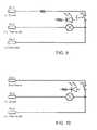
- the printed circuit 24 is designed in to implement the electrical circuits shown in Figures 9 and 10 , which refer to the use of a push-push switch and a momentary pushbutton switch, respectively.
- the electrical circuits shown in Figures 9 and 10 have the same circuit topology, with obvious benefits in terms of reduced area of occupation of the printed circuit 24, which enables the utilization of different types of switches by simply changing the external electrical connection implemented by the external electrical connector that engages, in use, seat 23 of the parabolic body 13, as will be explained below.
- the printed circuit 24 is designed to indifferently allow push-push switches or momentary pushbutton switches to be electrically connected, for example by soldering, at the electrical terminals 27 for the electrical switches 22 for which this option is contemplated.
- Each pair of electrical terminals 27 is constituted by the ends of two electrically conductive tracks, one of which electrically connects the electrical terminal of the corresponding pushbutton switch 22 to a first electrical I/O terminal 25 of the printed circuit 24, indicated in Figures 9 and 10 as "Pin 1", through an optional electrical resistor (which for this reason, is not shown in Figure 10 ) arranged along the electrically conductive track, while the other electrically conductive track electrically connects the electrical terminal of the corresponding pushbutton switch 22 to both a second electrical I/O terminal 25 of the printed circuit 24, indicated in Figures 9 and 10 as "Pin 3", and an electrical terminal of a corresponding electric light source 18 to be switched on/off, whether this be an incandescent electric light source (represented by an unbroken line) or a LED electric light source provided with an associated power supply resistor (represented by an broken line), the other electrical terminal of which is connected, by an electrically conductive track, to a third electrical I/O terminal 25 of the printed circuit 24, indicated in Figures 9 and 10 as "
- the corresponding electric light source 18 is switched on either when any door of the motor vehicle is open, as the electric light source 18 becomes connected between the power supply potential applied to the second electrical terminal Pin2 and the electric ground potential applied to the third electrical terminal Pin3, or when push-push switch 22 is pressed, as the electric light source 18 becomes connected between the power supply potential applied to the second electrical terminal Pin2 and the electric ground potential applied to the first electrical terminal Pin1.
- Figure 10 shows how the external electrical connections are made for the three electrical terminals Pin1, Pin2 and Pin3 of the printed circuit 24 when a momentary pushbutton switch is used.
- the printed circuit 24 is designed to provide, at the location of each electrical switch 22 that can be chosen as a backlit or non-backlit switch, two power supply terminals 27 to which it is possible to electrically connect, for example by soldering or crimping, corresponding electrical terminals of an electric backlight source, conveniently of the LED type, or, when necessary, multiple backlight power sources connected to each other in series, and which are constituted by the ends of two electrically conductive tracks connected to the electrical I/O terminals 25 of the printed circuit 24, so that they can be respectively polarized at a (positive) power supply potential and an electric ground potential.
- an electrical resistor in parallel with the backlight power source(s) is also required, while the provision and electrical connection of the electrical resistors necessary for correct polarization of the backlight power sources is performed using the technique previously described regarding reconfiguration of the overhead light assembly 1 as in a).
- connection of an electrical resistor in parallel with the backlight power source(s) can be performed by making an interrupted electrically conductive track connected in parallel to the electrical terminals to which the backlight power sources will be connected and the electrical continuity of which can be re-established by the connection of the electrical resistor the moment when the backlight power source(s) is/are connected to the associated electrical terminals for backlighting the electrical switch 22.
Landscapes
- Engineering & Computer Science (AREA)
- Mechanical Engineering (AREA)
- Arrangements Of Lighting Devices For Vehicle Interiors, Mounting And Supporting Thereof, Circuits Therefore (AREA)
- Vehicle Interior And Exterior Ornaments, Soundproofing, And Insulation (AREA)
- Non-Portable Lighting Devices Or Systems Thereof (AREA)
Applications Claiming Priority (1)
| Application Number | Priority Date | Filing Date | Title |
|---|---|---|---|
| IT000965A ITTO20120965A1 (it) | 2012-11-05 | 2012-11-05 | Plafoniera riconfigurabile autoveicolistica |
Publications (2)
| Publication Number | Publication Date |
|---|---|
| EP2727770A1 true EP2727770A1 (de) | 2014-05-07 |
| EP2727770B1 EP2727770B1 (de) | 2015-07-29 |
Family
ID=47471951
Family Applications (1)
| Application Number | Title | Priority Date | Filing Date |
|---|---|---|---|
| EP13191698.3A Active EP2727770B1 (de) | 2012-11-05 | 2013-11-05 | Rekonfigurierbare Autodeckenleuchtenanordnung |
Country Status (2)
| Country | Link |
|---|---|
| EP (1) | EP2727770B1 (de) |
| IT (1) | ITTO20120965A1 (de) |
Cited By (1)
| Publication number | Priority date | Publication date | Assignee | Title |
|---|---|---|---|---|
| US10101018B2 (en) | 2015-09-22 | 2018-10-16 | Ford Global Technologies, Llc | Dome light assembly with integral removable lamp unit for use in emergencies |
Citations (11)
| Publication number | Priority date | Publication date | Assignee | Title |
|---|---|---|---|---|
| EP0899157A1 (de) * | 1997-08-25 | 1999-03-03 | Donnelly Corporation | Rückblickspiegel in Modulbauweise |
| DE19848820A1 (de) * | 1997-10-24 | 1999-04-29 | Daiichi Denso Buhin K K | Kraftfahrzeuginnenraum-Leuchtenanordnung |
| US20020145871A1 (en) * | 2000-10-13 | 2002-10-10 | Takashi Yoda | Cabin lamp |
| DE10202955A1 (de) * | 2002-01-26 | 2003-08-14 | Apag Elektronik Ag Duebendorf | Modulare Innenleuchte für ein Kraftfahrzeug |
| US20040264205A1 (en) * | 2003-06-27 | 2004-12-30 | Tiesler John M. | Modular light assembly and method for installing a modular light assembly in a vehicle |
| US20050207158A1 (en) * | 2004-03-19 | 2005-09-22 | Yazaki Corporation | Interior illumination lamp |
| EP1853096A2 (de) * | 2006-05-03 | 2007-11-07 | Grote Industries, Inc. | Metallträger für LEDs in einer Leuchtanordnung |
| WO2008024985A2 (en) * | 2006-08-25 | 2008-02-28 | Johnson Controls Technology Company | Integrated power source for interior led lighting |
| US20090193640A1 (en) * | 2008-02-05 | 2009-08-06 | Putco, Inc. | Method and apparatus for replacing vehicle dome light |
| DE202009012306U1 (de) * | 2009-09-11 | 2009-12-17 | Johnson Controls Technology Company, Holland | Austauschbares Lichtmodul |
| US20100177530A1 (en) * | 2009-01-13 | 2010-07-15 | Ford Global Technologies, Llc | Vehicle headliner module |
-
2012
- 2012-11-05 IT IT000965A patent/ITTO20120965A1/it unknown
-
2013
- 2013-11-05 EP EP13191698.3A patent/EP2727770B1/de active Active
Patent Citations (12)
| Publication number | Priority date | Publication date | Assignee | Title |
|---|---|---|---|---|
| EP0899157A1 (de) * | 1997-08-25 | 1999-03-03 | Donnelly Corporation | Rückblickspiegel in Modulbauweise |
| DE19848820A1 (de) * | 1997-10-24 | 1999-04-29 | Daiichi Denso Buhin K K | Kraftfahrzeuginnenraum-Leuchtenanordnung |
| US20020145871A1 (en) * | 2000-10-13 | 2002-10-10 | Takashi Yoda | Cabin lamp |
| DE10202955A1 (de) * | 2002-01-26 | 2003-08-14 | Apag Elektronik Ag Duebendorf | Modulare Innenleuchte für ein Kraftfahrzeug |
| US20040264205A1 (en) * | 2003-06-27 | 2004-12-30 | Tiesler John M. | Modular light assembly and method for installing a modular light assembly in a vehicle |
| US20050207158A1 (en) * | 2004-03-19 | 2005-09-22 | Yazaki Corporation | Interior illumination lamp |
| EP1853096A2 (de) * | 2006-05-03 | 2007-11-07 | Grote Industries, Inc. | Metallträger für LEDs in einer Leuchtanordnung |
| US20070259576A1 (en) | 2006-05-03 | 2007-11-08 | Brandt Bruce B | Metal carrier for LEDs in composite lamps |
| WO2008024985A2 (en) * | 2006-08-25 | 2008-02-28 | Johnson Controls Technology Company | Integrated power source for interior led lighting |
| US20090193640A1 (en) * | 2008-02-05 | 2009-08-06 | Putco, Inc. | Method and apparatus for replacing vehicle dome light |
| US20100177530A1 (en) * | 2009-01-13 | 2010-07-15 | Ford Global Technologies, Llc | Vehicle headliner module |
| DE202009012306U1 (de) * | 2009-09-11 | 2009-12-17 | Johnson Controls Technology Company, Holland | Austauschbares Lichtmodul |
Cited By (1)
| Publication number | Priority date | Publication date | Assignee | Title |
|---|---|---|---|---|
| US10101018B2 (en) | 2015-09-22 | 2018-10-16 | Ford Global Technologies, Llc | Dome light assembly with integral removable lamp unit for use in emergencies |
Also Published As
| Publication number | Publication date |
|---|---|
| ITTO20120965A1 (it) | 2014-05-06 |
| EP2727770B1 (de) | 2015-07-29 |
Similar Documents
| Publication | Publication Date | Title |
|---|---|---|
| US7537256B2 (en) | Component module applique for vehicle lift gate | |
| CN100472688C (zh) | 组合操作开关组件 | |
| US10661754B2 (en) | Inside door handle system for a door of a vehicle | |
| US9328891B1 (en) | Vehicle lamp unit | |
| US7108309B2 (en) | Sun visor with conducting arm for vehicles | |
| US5756949A (en) | Unit structure for hazard switch | |
| US20130092519A1 (en) | Rotary switch | |
| KR101601512B1 (ko) | 자동차의 후면부 장착용 다기능 통합 모듈 | |
| CN201652096U (zh) | 车辆顶篷模块 | |
| EP2727770B1 (de) | Rekonfigurierbare Autodeckenleuchtenanordnung | |
| US6273593B1 (en) | Door and manually actuated vehicle interior lighting system | |
| KR20190052976A (ko) | 버스용 콜 부저 스위치 | |
| US20120184150A1 (en) | Electric cable holder and method for connecting the same | |
| KR101211311B1 (ko) | 차량의 멀티펑션 스위치 어셈블리 및 그 조립방법 | |
| US9045083B2 (en) | Integrated release switch assembly | |
| US20030053317A1 (en) | Raised brake light assembly for vehicles, especially motor vehicles | |
| US20030168881A1 (en) | Lock control assembly for a motor vehicle opening panel and opening panel equipped with same | |
| JP2010143357A (ja) | ルーフコンソールの照明構造 | |
| JP2007030768A (ja) | 車両用室内灯のバスバー間絶縁構造 | |
| JP4738928B2 (ja) | 車両用室内灯の防熱構造 | |
| CN202196670U (zh) | 调光雾灯开关 | |
| JP3151738B2 (ja) | 車両用灯具 | |
| JP2009274675A (ja) | 車載用室内照明装置 | |
| CN101515517B (zh) | 开关装置 | |
| KR200428942Y1 (ko) | 자동차용 룸 램프의 구조 |
Legal Events
| Date | Code | Title | Description |
|---|---|---|---|
| PUAI | Public reference made under article 153(3) epc to a published international application that has entered the european phase |
Free format text: ORIGINAL CODE: 0009012 |
|
| 17P | Request for examination filed |
Effective date: 20131105 |
|
| AK | Designated contracting states |
Kind code of ref document: A1 Designated state(s): AL AT BE BG CH CY CZ DE DK EE ES FI FR GB GR HR HU IE IS IT LI LT LU LV MC MK MT NL NO PL PT RO RS SE SI SK SM TR |
|
| AX | Request for extension of the european patent |
Extension state: BA ME |
|
| 17P | Request for examination filed |
Effective date: 20141106 |
|
| RBV | Designated contracting states (corrected) |
Designated state(s): AL AT BE BG CH CY CZ DE DK EE ES FI FR GB GR HR HU IE IS IT LI LT LU LV MC MK MT NL NO PL PT RO RS SE SI SK SM TR |
|
| RIC1 | Information provided on ipc code assigned before grant |
Ipc: B60Q 3/02 20060101AFI20150109BHEP |
|
| GRAP | Despatch of communication of intention to grant a patent |
Free format text: ORIGINAL CODE: EPIDOSNIGR1 |
|
| INTG | Intention to grant announced |
Effective date: 20150220 |
|
| GRAS | Grant fee paid |
Free format text: ORIGINAL CODE: EPIDOSNIGR3 |
|
| GRAA | (expected) grant |
Free format text: ORIGINAL CODE: 0009210 |
|
| AK | Designated contracting states |
Kind code of ref document: B1 Designated state(s): AL AT BE BG CH CY CZ DE DK EE ES FI FR GB GR HR HU IE IS IT LI LT LU LV MC MK MT NL NO PL PT RO RS SE SI SK SM TR |
|
| REG | Reference to a national code |
Ref country code: GB Ref legal event code: FG4D |
|
| REG | Reference to a national code |
Ref country code: CH Ref legal event code: EP |
|
| REG | Reference to a national code |
Ref country code: AT Ref legal event code: REF Ref document number: 738981 Country of ref document: AT Kind code of ref document: T Effective date: 20150815 |
|
| REG | Reference to a national code |
Ref country code: IE Ref legal event code: FG4D |
|
| REG | Reference to a national code |
Ref country code: DE Ref legal event code: R096 Ref document number: 602013002442 Country of ref document: DE |
|
| REG | Reference to a national code |
Ref country code: DE Ref legal event code: R082 Ref document number: 602013002442 Country of ref document: DE Representative=s name: ANDREJEWSKI - HONKE PATENT- UND RECHTSANWAELTE, DE |
|
| REG | Reference to a national code |
Ref country code: FR Ref legal event code: PLFP Year of fee payment: 3 |
|
| REG | Reference to a national code |
Ref country code: AT Ref legal event code: MK05 Ref document number: 738981 Country of ref document: AT Kind code of ref document: T Effective date: 20150729 |
|
| REG | Reference to a national code |
Ref country code: LT Ref legal event code: MG4D |
|
| REG | Reference to a national code |
Ref country code: NL Ref legal event code: MP Effective date: 20150729 |
|
| PG25 | Lapsed in a contracting state [announced via postgrant information from national office to epo] |
Ref country code: FI Free format text: LAPSE BECAUSE OF FAILURE TO SUBMIT A TRANSLATION OF THE DESCRIPTION OR TO PAY THE FEE WITHIN THE PRESCRIBED TIME-LIMIT Effective date: 20150729 Ref country code: LT Free format text: LAPSE BECAUSE OF FAILURE TO SUBMIT A TRANSLATION OF THE DESCRIPTION OR TO PAY THE FEE WITHIN THE PRESCRIBED TIME-LIMIT Effective date: 20150729 Ref country code: GR Free format text: LAPSE BECAUSE OF FAILURE TO SUBMIT A TRANSLATION OF THE DESCRIPTION OR TO PAY THE FEE WITHIN THE PRESCRIBED TIME-LIMIT Effective date: 20151030 Ref country code: NO Free format text: LAPSE BECAUSE OF FAILURE TO SUBMIT A TRANSLATION OF THE DESCRIPTION OR TO PAY THE FEE WITHIN THE PRESCRIBED TIME-LIMIT Effective date: 20151029 Ref country code: LV Free format text: LAPSE BECAUSE OF FAILURE TO SUBMIT A TRANSLATION OF THE DESCRIPTION OR TO PAY THE FEE WITHIN THE PRESCRIBED TIME-LIMIT Effective date: 20150729 |
|
| PG25 | Lapsed in a contracting state [announced via postgrant information from national office to epo] |
Ref country code: SE Free format text: LAPSE BECAUSE OF FAILURE TO SUBMIT A TRANSLATION OF THE DESCRIPTION OR TO PAY THE FEE WITHIN THE PRESCRIBED TIME-LIMIT Effective date: 20150729 Ref country code: PL Free format text: LAPSE BECAUSE OF FAILURE TO SUBMIT A TRANSLATION OF THE DESCRIPTION OR TO PAY THE FEE WITHIN THE PRESCRIBED TIME-LIMIT Effective date: 20150729 Ref country code: ES Free format text: LAPSE BECAUSE OF FAILURE TO SUBMIT A TRANSLATION OF THE DESCRIPTION OR TO PAY THE FEE WITHIN THE PRESCRIBED TIME-LIMIT Effective date: 20150729 Ref country code: RS Free format text: LAPSE BECAUSE OF FAILURE TO SUBMIT A TRANSLATION OF THE DESCRIPTION OR TO PAY THE FEE WITHIN THE PRESCRIBED TIME-LIMIT Effective date: 20150729 Ref country code: AT Free format text: LAPSE BECAUSE OF FAILURE TO SUBMIT A TRANSLATION OF THE DESCRIPTION OR TO PAY THE FEE WITHIN THE PRESCRIBED TIME-LIMIT Effective date: 20150729 Ref country code: IS Free format text: LAPSE BECAUSE OF FAILURE TO SUBMIT A TRANSLATION OF THE DESCRIPTION OR TO PAY THE FEE WITHIN THE PRESCRIBED TIME-LIMIT Effective date: 20151129 Ref country code: PT Free format text: LAPSE BECAUSE OF FAILURE TO SUBMIT A TRANSLATION OF THE DESCRIPTION OR TO PAY THE FEE WITHIN THE PRESCRIBED TIME-LIMIT Effective date: 20151130 Ref country code: HR Free format text: LAPSE BECAUSE OF FAILURE TO SUBMIT A TRANSLATION OF THE DESCRIPTION OR TO PAY THE FEE WITHIN THE PRESCRIBED TIME-LIMIT Effective date: 20150729 |
|
| PG25 | Lapsed in a contracting state [announced via postgrant information from national office to epo] |
Ref country code: NL Free format text: LAPSE BECAUSE OF FAILURE TO SUBMIT A TRANSLATION OF THE DESCRIPTION OR TO PAY THE FEE WITHIN THE PRESCRIBED TIME-LIMIT Effective date: 20150729 |
|
| PG25 | Lapsed in a contracting state [announced via postgrant information from national office to epo] |
Ref country code: EE Free format text: LAPSE BECAUSE OF FAILURE TO SUBMIT A TRANSLATION OF THE DESCRIPTION OR TO PAY THE FEE WITHIN THE PRESCRIBED TIME-LIMIT Effective date: 20150729 Ref country code: DK Free format text: LAPSE BECAUSE OF FAILURE TO SUBMIT A TRANSLATION OF THE DESCRIPTION OR TO PAY THE FEE WITHIN THE PRESCRIBED TIME-LIMIT Effective date: 20150729 Ref country code: SK Free format text: LAPSE BECAUSE OF FAILURE TO SUBMIT A TRANSLATION OF THE DESCRIPTION OR TO PAY THE FEE WITHIN THE PRESCRIBED TIME-LIMIT Effective date: 20150729 Ref country code: CZ Free format text: LAPSE BECAUSE OF FAILURE TO SUBMIT A TRANSLATION OF THE DESCRIPTION OR TO PAY THE FEE WITHIN THE PRESCRIBED TIME-LIMIT Effective date: 20150729 |
|
| REG | Reference to a national code |
Ref country code: DE Ref legal event code: R097 Ref document number: 602013002442 Country of ref document: DE |
|
| PG25 | Lapsed in a contracting state [announced via postgrant information from national office to epo] |
Ref country code: RO Free format text: LAPSE BECAUSE OF FAILURE TO SUBMIT A TRANSLATION OF THE DESCRIPTION OR TO PAY THE FEE WITHIN THE PRESCRIBED TIME-LIMIT Effective date: 20150729 |
|
| PLBE | No opposition filed within time limit |
Free format text: ORIGINAL CODE: 0009261 |
|
| STAA | Information on the status of an ep patent application or granted ep patent |
Free format text: STATUS: NO OPPOSITION FILED WITHIN TIME LIMIT |
|
| PG25 | Lapsed in a contracting state [announced via postgrant information from national office to epo] |
Ref country code: LU Free format text: LAPSE BECAUSE OF FAILURE TO SUBMIT A TRANSLATION OF THE DESCRIPTION OR TO PAY THE FEE WITHIN THE PRESCRIBED TIME-LIMIT Effective date: 20151105 Ref country code: MC Free format text: LAPSE BECAUSE OF FAILURE TO SUBMIT A TRANSLATION OF THE DESCRIPTION OR TO PAY THE FEE WITHIN THE PRESCRIBED TIME-LIMIT Effective date: 20150729 |
|
| 26N | No opposition filed |
Effective date: 20160502 |
|
| REG | Reference to a national code |
Ref country code: IE Ref legal event code: MM4A |
|
| PG25 | Lapsed in a contracting state [announced via postgrant information from national office to epo] |
Ref country code: SI Free format text: LAPSE BECAUSE OF FAILURE TO SUBMIT A TRANSLATION OF THE DESCRIPTION OR TO PAY THE FEE WITHIN THE PRESCRIBED TIME-LIMIT Effective date: 20150729 |
|
| PG25 | Lapsed in a contracting state [announced via postgrant information from national office to epo] |
Ref country code: IE Free format text: LAPSE BECAUSE OF NON-PAYMENT OF DUE FEES Effective date: 20151105 |
|
| REG | Reference to a national code |
Ref country code: DE Ref legal event code: R079 Ref document number: 602013002442 Country of ref document: DE Free format text: PREVIOUS MAIN CLASS: B60Q0003020000 Ipc: B60Q0003200000 Ref country code: FR Ref legal event code: PLFP Year of fee payment: 4 |
|
| PG25 | Lapsed in a contracting state [announced via postgrant information from national office to epo] |
Ref country code: BE Free format text: LAPSE BECAUSE OF FAILURE TO SUBMIT A TRANSLATION OF THE DESCRIPTION OR TO PAY THE FEE WITHIN THE PRESCRIBED TIME-LIMIT Effective date: 20150729 |
|
| PG25 | Lapsed in a contracting state [announced via postgrant information from national office to epo] |
Ref country code: HU Free format text: LAPSE BECAUSE OF FAILURE TO SUBMIT A TRANSLATION OF THE DESCRIPTION OR TO PAY THE FEE WITHIN THE PRESCRIBED TIME-LIMIT; INVALID AB INITIO Effective date: 20131105 Ref country code: BG Free format text: LAPSE BECAUSE OF FAILURE TO SUBMIT A TRANSLATION OF THE DESCRIPTION OR TO PAY THE FEE WITHIN THE PRESCRIBED TIME-LIMIT Effective date: 20150729 |
|
| PG25 | Lapsed in a contracting state [announced via postgrant information from national office to epo] |
Ref country code: CY Free format text: LAPSE BECAUSE OF FAILURE TO SUBMIT A TRANSLATION OF THE DESCRIPTION OR TO PAY THE FEE WITHIN THE PRESCRIBED TIME-LIMIT Effective date: 20150729 |
|
| REG | Reference to a national code |
Ref country code: CH Ref legal event code: PL |
|
| PG25 | Lapsed in a contracting state [announced via postgrant information from national office to epo] |
Ref country code: CH Free format text: LAPSE BECAUSE OF NON-PAYMENT OF DUE FEES Effective date: 20161130 Ref country code: LI Free format text: LAPSE BECAUSE OF NON-PAYMENT OF DUE FEES Effective date: 20161130 |
|
| PG25 | Lapsed in a contracting state [announced via postgrant information from national office to epo] |
Ref country code: MT Free format text: LAPSE BECAUSE OF FAILURE TO SUBMIT A TRANSLATION OF THE DESCRIPTION OR TO PAY THE FEE WITHIN THE PRESCRIBED TIME-LIMIT Effective date: 20150729 |
|
| REG | Reference to a national code |
Ref country code: FR Ref legal event code: PLFP Year of fee payment: 5 |
|
| PG25 | Lapsed in a contracting state [announced via postgrant information from national office to epo] |
Ref country code: SM Free format text: LAPSE BECAUSE OF FAILURE TO SUBMIT A TRANSLATION OF THE DESCRIPTION OR TO PAY THE FEE WITHIN THE PRESCRIBED TIME-LIMIT Effective date: 20150729 |
|
| PG25 | Lapsed in a contracting state [announced via postgrant information from national office to epo] |
Ref country code: MK Free format text: LAPSE BECAUSE OF FAILURE TO SUBMIT A TRANSLATION OF THE DESCRIPTION OR TO PAY THE FEE WITHIN THE PRESCRIBED TIME-LIMIT Effective date: 20150729 |
|
| GBPC | Gb: european patent ceased through non-payment of renewal fee |
Effective date: 20171105 |
|
| PG25 | Lapsed in a contracting state [announced via postgrant information from national office to epo] |
Ref country code: AL Free format text: LAPSE BECAUSE OF FAILURE TO SUBMIT A TRANSLATION OF THE DESCRIPTION OR TO PAY THE FEE WITHIN THE PRESCRIBED TIME-LIMIT Effective date: 20150729 Ref country code: TR Free format text: LAPSE BECAUSE OF FAILURE TO SUBMIT A TRANSLATION OF THE DESCRIPTION OR TO PAY THE FEE WITHIN THE PRESCRIBED TIME-LIMIT Effective date: 20150729 |
|
| PG25 | Lapsed in a contracting state [announced via postgrant information from national office to epo] |
Ref country code: GB Free format text: LAPSE BECAUSE OF NON-PAYMENT OF DUE FEES Effective date: 20171105 |
|
| PGFP | Annual fee paid to national office [announced via postgrant information from national office to epo] |
Ref country code: DE Payment date: 20241022 Year of fee payment: 12 |
|
| PGFP | Annual fee paid to national office [announced via postgrant information from national office to epo] |
Ref country code: FR Payment date: 20241022 Year of fee payment: 12 |
|
| PGFP | Annual fee paid to national office [announced via postgrant information from national office to epo] |
Ref country code: IT Payment date: 20241022 Year of fee payment: 12 |