EP2725312B1 - Verfahren und Vorrichtung zum Überwachen einer Kältemittelfüllmenge - Google Patents
Verfahren und Vorrichtung zum Überwachen einer Kältemittelfüllmenge Download PDFInfo
- Publication number
- EP2725312B1 EP2725312B1 EP13189217.6A EP13189217A EP2725312B1 EP 2725312 B1 EP2725312 B1 EP 2725312B1 EP 13189217 A EP13189217 A EP 13189217A EP 2725312 B1 EP2725312 B1 EP 2725312B1
- Authority
- EP
- European Patent Office
- Prior art keywords
- frequency distribution
- refrigerant
- refrigeration system
- period
- actual
- Prior art date
- Legal status (The legal status is an assumption and is not a legal conclusion. Google has not performed a legal analysis and makes no representation as to the accuracy of the status listed.)
- Not-in-force
Links
Images


Classifications
-
- F—MECHANICAL ENGINEERING; LIGHTING; HEATING; WEAPONS; BLASTING
- F25—REFRIGERATION OR COOLING; COMBINED HEATING AND REFRIGERATION SYSTEMS; HEAT PUMP SYSTEMS; MANUFACTURE OR STORAGE OF ICE; LIQUEFACTION SOLIDIFICATION OF GASES
- F25B—REFRIGERATION MACHINES, PLANTS OR SYSTEMS; COMBINED HEATING AND REFRIGERATION SYSTEMS; HEAT PUMP SYSTEMS
- F25B49/00—Arrangement or mounting of control or safety devices
- F25B49/005—Arrangement or mounting of control or safety devices of safety devices
-
- F—MECHANICAL ENGINEERING; LIGHTING; HEATING; WEAPONS; BLASTING
- F25—REFRIGERATION OR COOLING; COMBINED HEATING AND REFRIGERATION SYSTEMS; HEAT PUMP SYSTEMS; MANUFACTURE OR STORAGE OF ICE; LIQUEFACTION SOLIDIFICATION OF GASES
- F25B—REFRIGERATION MACHINES, PLANTS OR SYSTEMS; COMBINED HEATING AND REFRIGERATION SYSTEMS; HEAT PUMP SYSTEMS
- F25B2700/00—Sensing or detecting of parameters; Sensors therefor
- F25B2700/04—Refrigerant level
-
- F—MECHANICAL ENGINEERING; LIGHTING; HEATING; WEAPONS; BLASTING
- F25—REFRIGERATION OR COOLING; COMBINED HEATING AND REFRIGERATION SYSTEMS; HEAT PUMP SYSTEMS; MANUFACTURE OR STORAGE OF ICE; LIQUEFACTION SOLIDIFICATION OF GASES
- F25B—REFRIGERATION MACHINES, PLANTS OR SYSTEMS; COMBINED HEATING AND REFRIGERATION SYSTEMS; HEAT PUMP SYSTEMS
- F25B2700/00—Sensing or detecting of parameters; Sensors therefor
- F25B2700/21—Temperatures
- F25B2700/2116—Temperatures of a condenser
- F25B2700/21163—Temperatures of a condenser of the refrigerant at the outlet of the condenser
Definitions
- the invention relates to a method for monitoring the refrigerant charge of a refrigeration system, for. B. a compression refrigeration system for a supermarket with a plurality of branched cooling points, and a refrigeration system with a monitoring device for performing such a method.
- Compression refrigerators with closed refrigerant circuits require a certain amount of refrigerant charge for their intended function, these z. B. to ensure a sufficient cooling effect and to avoid damage to the refrigeration system must not fall below a predetermined minimum capacity.
- the refrigeration cycle of a compression refrigeration machine has z. B. a compressor, a condenser and an evaporator as components; wherein the minimum required refrigerant charge z. B. the internal volume of the refrigerant circuit, the type of components of the refrigerant circuit, the requested cooling capacity, load fluctuations and the respective operating conditions depends. Furthermore, z. B. in the interest of environmental protection emissions of greenhouse gases, which are caused by leakage of refrigerant to avoid. Therefore - z. B.
- the DE 41 39 064 A1 describes a method for detecting an overfill of an evaporator of a refrigeration system, by means of which the refrigerant is evaporated to a suction gas, wherein in the case of such overfilling in the suction gas remaining liquid droplets are detected by evaporation on a measuring body.
- the DE 10 2006 039 925 B4 describes a method for determining the refrigerant loss of a refrigeration system, wherein during a standstill of the refrigeration system, the refrigerant is sucked from the suction side of the compressor, conveyed to the pressure side of the compressor and stored in a refrigerant storage, the suction up to a predetermined pressure on the suction side of the Compressor is measured, which adjusts itself on the pressure side of the compressor high pressure and the measured high pressure is compared with the resulting in the desired filling amount of the refrigerant reference high pressure.
- the DE 10 2011 101 922 A1 describes a refrigeration cycle with a compressor, a condenser and an evaporator, wherein in the flow direction downstream of the condenser and upstream of the evaporator, a check valve is provided to selectively lock the cooling circuit for a measuring operation, and wherein at the condenser a weighing device is provided to during During measurement operation, weigh the condenser together with the refrigerant then contained.
- the invention provides a method for monitoring stochastically fluctuating levels, such as those found in technical systems of refrigeration, process engineering and chemical industry, but in particular for monitoring the refrigerant charge of a refrigeration system, provided by means of a reliable monitoring even during the current regular operation of the refrigeration system is possible.
- the invention provides a refrigeration system with a monitoring device designed to carry out such a method.
- a method for monitoring the refrigerant charge in the refrigerant circuit of a refrigeration system in the form of a compression refrigeration machine, wherein the refrigerant circuit comprises an evaporator, a compressor and a condenser.
- the method is over a predetermined period of time, z. B. by means of a corresponding sensor, a dependent of the refrigerant charge quantity (hereinafter also referred to as "filling quantity-sensitive variable”) detected.
- a quantity-sensitive measured variable e.g. the refrigerant level of a refrigerant reservoir of the refrigeration system or the subcooling of the liquid refrigerant are detected at the outlet of a condenser of the refrigeration system.
- the refrigeration system to a refrigerant reservoir, wherein the refrigerant level of the refrigerant reservoir is detected by means of a level sensor.
- the refrigeration system has a condenser, wherein the present at the outlet of the condenser subcooling of the liquid refrigerant is detected by means of a temperature sensor.
- a frequency distribution (hereinafter also referred to as "actual frequency distribution") is created, which describes how frequently a specific measured value of the measured variable was present within the given time period.
- the thus determined actual frequency distribution is compared with one or more reference frequency distributions, wherein such a reference frequency distribution z.
- B. represents a defined desired operating state or standard state of the refrigeration system with a known and sufficient refrigerant charge.
- Such a standard condition can z. B. plant-specific and can be determined in an initialization phase and subsequently -. B. in response to refrigerant replenishment - are constantly updated.
- an offset between the actual frequency distribution and one or more of the reference frequency distributions (eg a shift of the actual frequency distribution relative to one of the reference frequency distributions) is determined and, based on the determined offset, evaluates the refrigerant charge or refrigerant charge state of the refrigeration system.
- the monitored compression refrigeration machine has z. B. a refrigerant circuit with an evaporator, a compressor and a condenser. If the total refrigerant charge in the refrigerant circuit changes, the values of different parameters also change at different positions of the refrigerant circuit, such parameters thus being able to be used as a fill-quantity-sensitive measured variable.
- the refrigeration system z. B. have a refrigerant reservoir, wherein a change in the refrigerant charge is associated with a change in the refrigerant level in the refrigerant reservoir and thus the refrigerant level can be provided as a fill-quantity-sensitive measurement.
- the refrigeration system can accordingly have a level sensor for detecting the refrigerant level.
- a change in the refrigerant charge is accompanied by a change in the temperature at predetermined positions of the refrigerant circuit -.
- B. with a change in the subcooling of the liquid refrigerant at the outlet of condensers of the refrigeration system, which can cause liquid undercooling due to their design (eg condenser tube or tubular boiler with condensation on the pipe in the shell space or plate type) - so one Temperature can also be provided as a fill-quantity-sensitive measurement.
- the refrigeration system may have a correspondingly positioned temperature sensor.
- a change in the refrigerant charge is accompanied by a change in the pressure at predetermined positions of the refrigerant circuit, so that such a pressure can also be provided as a fill-quantity-sensitive measurement.
- the refrigeration system may have a correspondingly positioned pressure sensor.
- a change in the refrigerant charge is accompanied by a change in the frequency and the size spectrum of gas bubbles in liquid-carrying refrigerant lines of the refrigerant circuit, so that these variables can also be provided as a fill-quantity-sensitive measurement.
- the refrigeration system may have correspondingly positioned (eg optical) sensors.
- the values of such fill quantity-sensitive parameters or measured variables are a measure of the refrigerant charge present in the refrigerant circuit of the refrigeration system, wherein a change in the value of such a fill-quantity-sensitive measured variable indicates a change in the refrigerant charge.
- a reduction of the liquid level or refrigerant level in a refrigerant reservoir z. B. indicate a loss of refrigerant, whereas an increase in the refrigerant level in the refrigerant reservoir z. B. may indicate a refrigerant replenishment.
- time series which describe the time course of the measured values of a fill-quantity-sensitive measured variable likewise show corresponding fluctuations and are strongly stochastic. Such time series are therefore not reliably reproducible and thus do not form a meaningful, reliable basis for comparison or evaluation basis for evaluating the refrigerant charge present in the refrigerant circuit.
- a time series which describes the time profile of the measured values of a fill-quantity-sensitive measured variable over a predetermined period of time is not used as a basis for comparison for monitoring the refrigerant charge.
- a frequency distribution which describes the frequency of occurrence of a specific measured value of a quantity-sensitive measured variable within the given period of time is used as a basis for comparison.
- the comparison basis can be largely independent of the stochastic fluctuations of the measured values of the fill quantity-sensitive measured variables occurring during the regular operation of the refrigeration system and thus reliable monitoring of the refrigerant charge even during the regular operation of the refrigeration system can be realized.
- the proposed method may, for. B. be realized by means of a diagnostic system with appropriate software and used both for online and offline diagnosis of the operating situation.
- the diagnostic system with which the method is operated z. B. from a measuring device for continuous detection of at least one fill quantity-sensitive parameter and other suitable for assessing and filtering of operating conditions heranziehbarer parameters (eg suction pressure, backpressure, suction gas temperature, compressor power stage / - drive speed / frequency), and optionally a device for Monitoring indicators to identify specific plant operations (eg heat recovery, air conditioning / heat pump regimes).
- the software for online or offline diagnosis of the operating situation of the monitored refrigeration system has z. B.
- a data interface for continuous or buffered acquisition of data packets, a filter for the purpose of limiting the system description and evaluation of permissible operating conditions, a module for generating reference frequency distributions or reference patterns of standard conditions and for generating actual frequency distributions of an actual state the refrigeration system and for comparison of standard and actual state, and a module for interpreting the state comparison, possibly taking into account further system state data on.
- the reference frequency distributions used as a basis for comparison may, for. B. predetermined frequency distributions, which are created under controlled laboratory conditions in the presence of known, defined operating parameters (eg., With known, different refrigerant charge quantities and temporal operations), so that each of these reference frequency distributions a defined operating state of the refrigeration system.
- the reference frequency distributions are learned automatically in a learning phase or initialization phase, z. For example, by recording frequency distributions of a fill-quantity-sensitive measured value over a plurality of predefined periods, and if these frequency distributions sufficiently match, they are used as reference frequency distributions or a reference frequency distribution is formed therefrom (eg by averaging).
- the reference frequency distributions may be created in any other way, e.g. By external specification (eg based on empirical values) of any curve shape or functional dependency.
- the offset of the actual frequency distribution of one of the reference frequency distributions may, for. B. be given by a shift of the actual frequency distribution over the reference frequency distribution.
- the measured values of the fill-quantity-sensitive measured variables z. B. continuously or discretely are detected.
- the monitoring method is particularly suitable for refrigeration systems with multiple branched cooling points, z. B. for a refrigeration system in a supermarket, since a central detection of the filling quantity-sensitive measurement at a single position of the refrigeration system is sufficient.
- the method may, for. B. for determining the refrigerant charge per se or for detecting a change in the refrigerant charge amount (eg., Due to a refrigerant leakage) may be provided. It may be provided to output a signal if the amount of the determined offset between the actual frequency distribution and one of the reference frequency distributions exceeds a predetermined threshold value; wherein the signal z. B. may be an acoustic or optical signal or a text message.
- the actual frequency distribution and the reference frequency distributions may be absolute or relative (ie normalized with respect to the total number of measured values acquired within the given period of time).
- relative frequency distributions z. B. even with different numbers of underlying measurements allows a meaningful comparison of two frequency distributions.
- the refrigeration system is operated periodically, wherein the predetermined period (for determining the actual frequency distribution) corresponds to an operating period of the refrigeration system.
- the refrigeration system is operated periodically, i. H. the temporal operation of the refrigeration system has a periodicity (although the above-described stochastic fluctuations do not follow this periodicity).
- Many refrigeration systems follow z. B. on consecutive days always one and the same operation, the period is thus as an example 24 hours.
- refrigeration systems used in supermarkets follow on the one hand on successive open-sales days on the basis of this period of an operation with a period of 24 hours, on the other hand, taking into account z. On the basis of this period, for example, Sundays that are not open for sale can also be run for a period of one week.
- the operating period duration is the smallest period of time during which all influencing variables relevant for the frequency distribution of the measured values of the quantities that are variable in quantity can be completely recorded and taken into account. Since the period of time underlying the determination of the frequency distribution corresponds exactly to one operating period duration, reliable monitoring of the refrigerant charge level at the same time as a small response time is thus possible.
- periodic processes can be well characterized by characteristic patterns representing an operating period (here: characteristic frequency distributions).
- the period of time prescribed for establishing the frequency distribution does not correspond to a complete operating period of the refrigeration system, but merely to a characteristic subarea or time range of such a period.
- At least one of the reference frequency distributions is created by detecting the fill quantity-sensitive measured variable over a reference period (eg during the regular operation of the refrigeration system) and the reference frequency distribution describes how frequently a specific measured value of the Within the reference period, the reference period has the same duration as the specified period.
- reference frequency distribution present reference pattern is formed.
- the frequency distributions may be classified and classified into typical pattern types, which patterns shift with changes in refrigerant charge, and where the pattern structure (e.g. B. several maxima and minima of the frequency distribution) is maintained in such a shift in itself.
- the pattern structure e.g. B. several maxima and minima of the frequency distribution
- these patterns or frequency distributions z. B. occurrence of leakage and concomitant loss of refrigerant in the direction of the classes of lower refrigerant charge, with refrigerant replenishment in the direction of the classes of higher refrigerant charge.
- the measured value range of the fill quantity-sensitive measured variable is divided into a plurality of (eg equally wide) classes, wherein the actual frequency distribution and at least one of the reference frequency distributions are correspondingly classified frequency distributions.
- the example of the refrigerant level in a refrigerant reservoir as a filling quantity-sensitive measurement can z. B. be provided to divide the measured value range of the level in 10 classes, the width of each of the classes is 10% of the maximum possible level.
- the difference between a characteristic parameter (eg, an extremum, centroid, median, etc.) of the actual frequency distribution and the corresponding parameter of one of the reference frequency distributions becomes the offset between the actual frequency distribution and the Reference frequency distribution determined.
- a characteristic parameter eg, an extremum, centroid, median, etc.
- the offset or the (signed) distance between a maximum of the actual frequency distribution and a maximum of one of the reference frequency distributions is determined as the offset between the actual frequency distribution and the reference frequency distribution.
- the refrigerant level in a refrigerant reservoir as a filling quantity-sensitive measurement, it may, for. B. be considered as a reduction of the refrigerant charge by a leak when the (global) maximum of the actual frequency distribution over the (global) maximum of a reference frequency distribution offset or shifted to lower refrigerant levels.
- it may, for. B. are evaluated as an increase in the refrigerant charge by refrigerant replenishment when the (global) maximum of the actual frequency distribution over the (global) maximum of a reference frequency distribution offset or shifted to higher refrigerant levels.
- the actual frequency distribution and / or the reference frequency distribution is not clearly defined (global) maximum - to use other characteristic quantities or parameters of these frequency distributions (eg the center of gravity, the median, ascending or descending flanks in the course of the curve) for determining the offset and, for example, B. to determine the offset or the distance between the center of gravity of the actual frequency distribution and the center of gravity of the reference frequency distribution as the offset of the actual frequency distribution with respect to the reference frequency distribution.
- each of the reference frequency distributions functions as a reference pattern type, wherein the actual frequency distribution is fed to a classifier (i.e., subjected to a classification process) and assigned by the classifier to one of the reference pattern types.
- a classifier i.e., subjected to a classification process
- the monitoring process can be even more stable and reliable.
- the use of such a pattern recognition is provided in particular in the monitoring of periodically operated refrigeration systems, since it is precisely here due to the periodicity typical, well characterizable and classifiable patterns can be registered.
- the offset or distance (parallel to the measured value coordinate of the frequency distribution) between the actual frequency distribution and the reference pattern, to which the actual frequency distribution has been assigned as an offset between the actual frequency distribution and the reference frequency.
- the minimization of the deviation between the shifted actual frequency curve and the reference pattern can be carried out by means of customary minimization methods known to the person skilled in the art.
- each of the reference frequency distributions acting as a reference pattern, wherein each of these reference pattern types is blurred by means of configurable membership functions and the actual distribution is fuzzy Classifier is assigned to one of the reference pattern types.
- fuzzy description of the reference patterns in the context of fuzzy logic allows z. As a recognition of non-identical, but similar frequency distributions as belonging to the same pattern or pattern type.
- each of the reference patterns present in the form of the reference frequency distributions by means of membership functions, by structurally equating each reference frequency distribution in each of the classes (preferably asymmetric) membership functions is described out of focus.
- the creation of such typical reference patterns or reference frequency distributions can be done by an automated learning process or by the specification of expert knowledge (learning phase), whereby a standard state of the refrigeration system corresponding comparison patterns are generated. In the working phase then delivers z.
- the current actual frequency distribution is then fed to a fuzzy pattern classifier, which works with the special parameters of a reference pattern to be compared and determines a fuzzy affiliation (sympathy value) to this reference pattern.
- the current actual frequency distribution is shifted so that the sympathy value reaches a maximum for this reference pattern. If this sympathy score is lower than a given threshold, the reference pattern is considered unidentified.
- the next reference pattern is scanned by the same procedure. Becomes one of the actual frequency distribution If the corresponding reference pattern is recognized (eg by the determined sympathetic value being greater than a predefined limit value), it can be determined by determining the offset between the current actual frequency distribution and this reference pattern whether a pattern shift exists.
- a pattern shift is interpreted as an indication of a possible change in the refrigerant charge. To ensure a reliable assessment of the pattern shift, additional indicators may be included if necessary.
- refrigerant charge level is provided in a refrigerant reservoir of the refrigeration system as a fill quantity-sensitive measured variable
- an offset of the actual frequency distribution with respect to the reference frequency distribution toward higher fill levels is rated as refrigerant charge.
- a refrigeration system is provided with a monitoring device, wherein the monitoring device is designed to carry out the monitoring method according to one of the embodiments described above.
- FIG. 1 illustrates a refrigerant reservoir 1 of a refrigeration system 2, not shown in the form of a Kompressionskarltemaschine 2, wherein the refrigerant reservoir 1 is integrated into the refrigerant circuit 3 of the refrigeration system and is provided for receiving or intermediate buffers of liquid refrigerant 5.
- the refrigerant reservoir 3 is provided with a refrigerant level sensor 7 in the form of a rod level sensor for detecting the refrigerant level in the refrigerant reservoir 1.
- a change in the total amount of refrigerant in the refrigeration system 2 or the refrigerant circuit 3 results in a change in the refrigerant level in the refrigerant receiver or refrigerant reservoir 1; ie, the refrigerant level represents a fill-quantity-sensitive measurement.
- FIG. 2 illustrates the time profile of the measured values of the refrigerant level F in the refrigerant reservoir 1 during the regular operation of the refrigeration system 2, wherein the refrigerant level F is given as an indication in percent "%" of the maximum possible filling level (ie based on the maximum possible level) over the time t is plotted.
- the time profile of the refrigerant level F for two periods T of the temporal operating sequence of the refrigeration system 2 is illustrated, wherein the total amount of refrigerant present in the refrigerant circuit 3 is constant during this time.
- the time evolution of the refrigerant level F according to FIG. 2 represents as an example a defined error-free reference operating state or standard state of the refrigeration system 2 with a known and sufficient refrigerant charge F.
- the fill-quantity-sensitive measured variable in the form of the refrigerant level F varies considerably (for example due to stochastic influences) despite the constant refrigerant charge, whereby the time course of the refrigerant charge F is strongly stochastically shaped and thus the comparison of the time course of the refrigerant charge F within the first Period T1 with the time course of the refrigerant level F within the second period T2 is not suitable as a basis for comparison for accurate and reliable monitoring of the refrigerant charge.
- the frequency distributions describing how many times a particular measurement of the level F occurs during a period of operation T of the refrigeration system are essentially independent of the stochastic fluctuations the corresponding time courses; wherein, especially on the basis of periodic time sequences, characteristic patterns of the frequency distributions can be registered for the respective refrigeration system which, although they shift as the refrigerant charge is changed, essentially retain their structure.
- the frequency distributions of the measured values of the refrigerant level F within the first period T1 and the second period T2 according to FIG. 2 almost identical, and are in FIG. 3 as (a single) reference frequency distribution R1.
- the reference frequency distribution R1 thus represents a defined, error-free standard state of the refrigeration system 2.
- the refrigerant level F is now detected over the period of a period T across as a fill quantity-sensitive measured variable and an actual frequency distribution is created which describes how often a specific measured value of the refrigerant level F within this period T was present.
- FIG. 3 is shown as an example such an actual frequency distribution H1.
- FIG. 3 illustrates the frequency P of the occurrence of a measured value of the refrigerant level F within the period of a period T (ie, each of the frequency distributions H1, R1 is based on a detection period of T).
- the filling amount-sensitive measured quantity F is continuously detected, and both the actual frequency distribution H1 and the reference frequency distribution R1 are continuous frequency distributions.
- Both the actual frequency distribution H1 and the reference frequency distribution R1 are relative frequency distributions, the frequency P also being given as a percentage "%", ie the relative frequency of the occurrence of a measured value with respect to the total number of times recorded during the period of one period T Measurements reflects.
- the reference frequency distribution R1 is established by detecting the level F over a reference period and detecting the frequency of occurrence of the respective measured values, the reference period corresponding to a period T and thus to the detection period for the detection of the actual Frequency distribution H1 is identical or nearly identical.
- the offset of the actual frequency distribution H1 with respect to the reference frequency distribution R1 is determined.
- the offset is determined by determining the (signed) distance or offset 9 between the maximum M R of the reference frequency distribution R1 and the maximum M H of the actual frequency distribution H1 as an offset.
- the maximum M R of the reference frequency distribution R1 at a fill level F of approximately 70% and the maximum M H of the actual frequency distribution H1 at a fill level of approximately 60% which is an offset of the actual frequency distribution H1 the reference frequency distribution R1 is evaluated towards lower refrigerant levels and is signaled as leakage.
- an offset of the actual frequency distribution H1 versus the reference frequency distribution R1 toward higher refrigerant levels would be counted as refrigerant replenishment.
- FIG. 4 illustrates the relative frequency P of the occurrence of a respective measured value of the refrigerant level F within the period of a period T of the operation of the refrigeration system 2.
- FIG. 4 are illustrated as an example of the current operating state of the refrigeration system 2 corresponding actual frequency distribution H2 and two reference frequency distributions R2, R3.
- the distributions H2, R2 and R3 are each registered over the period of a period T time frequency distributions.
- FIG. 4 illustrated embodiment of the measured value range of the measured variable F divided into several classes, wherein the actual frequency distribution H2 and the reference frequency distributions R2, R3 are classified according to frequency distributions.
- the measured value range of the refrigerant level F is subdivided into 10 contiguous classes with a class width of 10% each of the maximum fill level of 100%, the frequency P corresponding to the respective class being plotted in each case in the middle of the value range of this class (in FIG FIG. 4 each indicated as a larger point).
- FIG. 4 each indicated as a larger point
- the points belonging to a respective distribution of frequencies are interconnected for better clarification by lines; wherein the points belonging to the actual frequency distribution H2 and the points belonging to the reference frequency distribution R2 are connected to each other by solid lines, and the points belonging to the reference frequency distribution R3 are connected to each other by a dashed line.
- the detected actual frequency distribution H2 is compared with a plurality (here: two) reference frequency distributions R2 and R3, wherein the reference frequency distributions R2 and R3 function respectively as a reference pattern and respectively represent a reference pattern.
- the actual frequency distribution H2 is fed to a classifier and assigned to one of the two reference patterns R2, R3 by means of the classifier.
- the form of the actual frequency distribution H2 is identical to the form of the reference frequency distribution R2; whereas the shape of the actual frequency distribution H2 deviates considerably from the form of the reference frequency distribution R3.
- the actual frequency distribution H2 is therefore assigned to the reference pattern type R2.
- the offset between the actual frequency distribution H2 and the reference pattern R2 is now determined, this offset in the present case corresponding to the displacement 13 of the actual frequency distribution H2 with respect to the reference pattern R2.
- the actual frequency distribution H2 towards the reference pattern R2 shifted to lower refrigerant levels F, which is considered as refrigerant loss due to leakage.
- an actual frequency distribution H2 z. B. be assigned as follows a reference pattern R2, R3.
- a measure for the deviation between the actual frequency distribution H2 and a respective reference pattern R2, R3 is defined.
- a measure of the deviation between an actual frequency distribution and a reference pattern may, for. For example, the amount of the distance between the frequency value of the actual frequency distribution and the frequency value of the reference pattern (in this class) is first determined for each class, and then these amounts are summed up for all classes. Now, the actual frequency distribution is shifted (computationally) along the filling level classes such that the above sum is minimized for each reference pattern, this minimum sum value being regarded as a deviation between the actual frequency distribution and the respective reference pattern.
- the minimum value of this sum is a quality criterion for the assignment of the actual frequency distribution to one of the reference patterns, wherein the actual frequency distribution z.
- the reference pattern is assigned to the reference pattern that has the smallest deviation from the actual frequency distribution among all reference patterns (i.e., the actual frequency distribution is assigned to the reference pattern with respect to which the predefined deviation is minimized).
- the shift of the actual frequency distribution required for minimizing the above-defined sum with respect to this reference pattern is determined as the offset between the actual frequency distribution and the reference pattern and the reference frequency distribution, respectively.
- each of the classified reference frequency distributions R2, R3 according to FIG. 4 in each filling level class by means of parameterizable, asymmetric state functions to describe out of focus and to detect the affiliation of an actual frequency distribution H2 to such a typical reference frequency distribution R2, R3 by means of a fuzzy classifier or fuzzy pattern classifier.
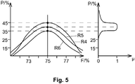
- FIG. 5 illustrates the procedure for the fuzzy description of a classified reference frequency distribution by means of asymmetrical membership functions in a given class.
- the left graph in FIG. 5 a section of several (here: three) reference frequency distributions R4, R5 and R6, which represent one and the same operating state or standard state of the refrigeration system (but slightly different due to stochastic fluctuations).
- the distributions R4, R5 and R6 have different frequency values P for the filling level class with the value range from 70% to 80% (in FIG. 5 characterized by the larger points), ie even if the standard state of the refrigeration system remains the same, this class value varies within a certain range.
- reference frequency distributions R4, R5 and R6 all represent one and the same standard state and are very similar to each other, therefore they are considered to belong to one and the same reference pattern, this reference pattern again being represented by the functions R4, R5 and R6 is writable as follows.
- the variation of the class value for each level can be described by a membership function ⁇ for each class; where the membership function ⁇ describes with which weight a measured frequency value is still considered to belong to the reference pattern defined by the reference frequency distributions R4, R5 and R6 (illustrated in the right-hand graph in FIG FIG. 5 ).
- a membership function ⁇ is determined; wherein again a blurred reference frequency distribution is defined by the totality of all these membership functions.
- the actual frequency value P for each level class is assigned a weight ⁇ (P) by means of the membership function ⁇ of the respective class, which describes how great the match of the actual frequency distribution with the unfixed reference frequency distribution in the class being considered.
Applications Claiming Priority (2)
| Application Number | Priority Date | Filing Date | Title |
|---|---|---|---|
| DE102012110183 | 2012-10-25 | ||
| DE102013100410.5A DE102013100410A1 (de) | 2012-10-25 | 2013-01-16 | Verfahren und Vorrichtung zum Überwachen einer Kältemittelfüllmenge |
Publications (3)
| Publication Number | Publication Date |
|---|---|
| EP2725312A2 EP2725312A2 (de) | 2014-04-30 |
| EP2725312A3 EP2725312A3 (de) | 2016-06-15 |
| EP2725312B1 true EP2725312B1 (de) | 2017-09-20 |
Family
ID=49385149
Family Applications (1)
| Application Number | Title | Priority Date | Filing Date |
|---|---|---|---|
| EP13189217.6A Not-in-force EP2725312B1 (de) | 2012-10-25 | 2013-10-18 | Verfahren und Vorrichtung zum Überwachen einer Kältemittelfüllmenge |
Country Status (2)
| Country | Link |
|---|---|
| EP (1) | EP2725312B1 (no) |
| DE (1) | DE102013100410A1 (no) |
Families Citing this family (3)
| Publication number | Priority date | Publication date | Assignee | Title |
|---|---|---|---|---|
| DE102017122126A1 (de) | 2017-09-25 | 2019-03-28 | Vaillant Gmbh | Leckage-Erkennung |
| JP6696533B2 (ja) * | 2018-06-22 | 2020-05-20 | ダイキン工業株式会社 | 冷凍装置 |
| US11085683B2 (en) * | 2018-06-22 | 2021-08-10 | Emerson Climate Technologies Retail Solutions, Inc. | Systems and methods for optical detection of refrigeration system abnormalities |
Family Cites Families (15)
| Publication number | Priority date | Publication date | Assignee | Title |
|---|---|---|---|---|
| DE3913521C2 (de) | 1989-04-25 | 1996-09-12 | Gerald Hemm | Verfahren zum Erkennen von Leckstellen im Kältemittelkreislauf einer Kälteanlage |
| DE3928430C1 (no) * | 1989-08-28 | 1991-03-07 | Linde Ag, 6200 Wiesbaden, De | |
| US5724822A (en) * | 1991-07-03 | 1998-03-10 | Nira Automotive Ab | Determining the amount of working fluid in a refrigeration or heat pump system |
| DE4139064C2 (de) * | 1991-11-28 | 1996-10-10 | Wilhelm Dr Buck | Verfahren zur Überwachung des Füllungsgrads eines Kältemittelverdampfers |
| DE19603175A1 (de) * | 1996-01-30 | 1997-07-31 | Wilhelm Dr Buck | Verfahren und Einrichtung zur Überwachung, Einstellung und Regelung des Füllungsgrads eines Kältemittelverdampfers |
| DE19754847A1 (de) * | 1997-12-10 | 1999-06-17 | Buna Sow Leuna Olefinverb Gmbh | Verfahren zur uni- und multivariaten Zuordnung von Analysenwerten zu einer definierten Norm To in der online Prozeßanalytik |
| US7159408B2 (en) * | 2004-07-28 | 2007-01-09 | Carrier Corporation | Charge loss detection and prognostics for multi-modular split systems |
| US7134291B2 (en) * | 2004-09-22 | 2006-11-14 | Horan Christopher J | Process for refrigerant charge level detection using a neural net having one output neuron |
| DE102006039925B4 (de) | 2006-08-25 | 2011-01-27 | Kriwan Industrie-Elektronik Gmbh | Verfahren zur Bestimmung des Kältemittelverlusts von Kälteanlagen |
| DE102007021874B4 (de) * | 2007-05-10 | 2015-12-17 | Bayerische Motoren Werke Aktiengesellschaft | Verfahren zur Kältemittel-Füllmengenüberwachung |
| DE102008052210A1 (de) * | 2008-10-17 | 2010-04-22 | DENSO CORPORATION, Kariya-shi | Verfahren und Vorrichtung zum Feststellen eines Verlusts an Kältemittel in einem Kältekreis |
| JP4975052B2 (ja) * | 2009-03-30 | 2012-07-11 | 三菱電機株式会社 | 冷凍サイクル装置 |
| US8973380B2 (en) * | 2009-05-28 | 2015-03-10 | Schneider Electric It Corporation | Systems and methods for detecting refrigerant leaks in cooling systems |
| DE102011101922A1 (de) | 2010-05-20 | 2011-11-24 | Epta Deutschland Gmbh | Kühlkreis |
| WO2012049535A1 (en) * | 2010-10-15 | 2012-04-19 | Freescale Semiconductor, Inc. | Decoder unit for determining a substance or material structure of a detected object based on signals of a capacitive sensor and method for determining a substance or material structure of a detected object based on signals of a capacitive sensor |
-
2013
- 2013-01-16 DE DE102013100410.5A patent/DE102013100410A1/de not_active Withdrawn
- 2013-10-18 EP EP13189217.6A patent/EP2725312B1/de not_active Not-in-force
Non-Patent Citations (1)
| Title |
|---|
| None * |
Also Published As
| Publication number | Publication date |
|---|---|
| EP2725312A3 (de) | 2016-06-15 |
| DE102013100410A1 (de) | 2014-05-15 |
| EP2725312A2 (de) | 2014-04-30 |
Similar Documents
| Publication | Publication Date | Title |
|---|---|---|
| EP3341222B1 (de) | Verfahren zum bestimmen einer profiltiefe eines reifenprofils, sowie steuergerät hierfür | |
| EP3341223B1 (de) | Verfahren zum bestimmen von reifencharakteristischen einflussgrössen, sowie steuergerät hierfür | |
| DE102015221350A1 (de) | Verfahren zum liefern eines qualitätsmasses für messgerät überprüfungsergebnisse | |
| EP3210088B1 (de) | Verfahren und assistenzsystem zur erkennung einer störung in einer anlage | |
| EP2633374A1 (de) | Instandhaltungsinformationsvorrichtung, zustandssensor zur verwendung darin sowie damit durchführbares verfahren zur entscheidungsfindung für oder gegen eine instandhaltung | |
| DE102012103652A1 (de) | Verfahren, Computerprogramm und System zur Durchführung der Interpolation bei Sensordaten zur Erzielung einer hohen Systemverfügbarkeit | |
| EP3390967A1 (de) | Verfahren zum überwachen von mindestens zwei redundanten sensoren | |
| EP2725312B1 (de) | Verfahren und Vorrichtung zum Überwachen einer Kältemittelfüllmenge | |
| EP3282399A1 (de) | Verfahren zur verbesserten erkennung von prozessanomalien einer technischen anlage sowie entsprechendes diagnosesystem | |
| DE10085170B4 (de) | Statistischer Trendgenerator zur prädiktiven Instrumentenwartung | |
| DE10348608A1 (de) | Spindelvorrichtung mit Zustandsüberwachung sowie entsprechendes Überwachungsverfahren und -system | |
| DE102006000220A1 (de) | Verfahren zur Leckerkennung an Rohrleitungen | |
| DE102007008968A1 (de) | Verfahren zum Erkennen von Wassereintrag in Dampfturbinen | |
| DE102017104414B3 (de) | Verfahren und Vorrichtung zum Bestimmen eines Indikators für eine Vorhersage einer Instabilität in einem Verdichter sowie Verwendung | |
| EP1817745B1 (de) | Verfahren zum ermitteln einer information über eine einer temperatur ausgesetzten vorrichtung | |
| DE102007021874A1 (de) | Verfahren und Klimaanlagensteuergerät zur Kältemittel-Füllmengenüberwachung | |
| DE102020126900A1 (de) | Verfahren zum Erfassen eines Ölzustands eines Betriebsöls, Steuer- und Regeleinrichtung sowie Brennkraftmaschine | |
| EP2350758B1 (de) | Verfahren zur überwachung einer potentiometrischen messsonde | |
| DE102016220195A1 (de) | Verfahren und Messanordnung zur Erfassung von Schlupf bei Wälzlagern | |
| WO2020132708A1 (de) | Verfahren zur überwachung der lebensdauer eines verbauten wälzlagers | |
| DE102013100411B4 (de) | Verfahren und Vorrichtung zur Zustandsüberwachung einer Kälteanlage | |
| AT523414B1 (de) | Verfahren zur Bestimmung der Schüttdichte von Schüttgut in einem mobilen Brecher | |
| WO2020259982A1 (de) | Verfahren zum bestimmen und angeben der reststandzeit eines filters | |
| DE102017108281B4 (de) | Brennkraftmaschine und Verfahren zum Überwachen der Brennkraftmaschine | |
| WO2005085619A1 (de) | Verfahren zur diagnose eines drucksensors |
Legal Events
| Date | Code | Title | Description |
|---|---|---|---|
| PUAI | Public reference made under article 153(3) epc to a published international application that has entered the european phase |
Free format text: ORIGINAL CODE: 0009012 |
|
| 17P | Request for examination filed |
Effective date: 20131018 |
|
| AK | Designated contracting states |
Kind code of ref document: A2 Designated state(s): AL AT BE BG CH CY CZ DE DK EE ES FI FR GB GR HR HU IE IS IT LI LT LU LV MC MK MT NL NO PL PT RO RS SE SI SK SM TR |
|
| AX | Request for extension of the european patent |
Extension state: BA ME |
|
| PUAL | Search report despatched |
Free format text: ORIGINAL CODE: 0009013 |
|
| AK | Designated contracting states |
Kind code of ref document: A3 Designated state(s): AL AT BE BG CH CY CZ DE DK EE ES FI FR GB GR HR HU IE IS IT LI LT LU LV MC MK MT NL NO PL PT RO RS SE SI SK SM TR |
|
| AX | Request for extension of the european patent |
Extension state: BA ME |
|
| RIC1 | Information provided on ipc code assigned before grant |
Ipc: F25B 49/00 20060101AFI20160509BHEP |
|
| 17P | Request for examination filed |
Effective date: 20161207 |
|
| RBV | Designated contracting states (corrected) |
Designated state(s): AL AT BE BG CH CY CZ DE DK EE ES FI FR GB GR HR HU IE IS IT LI LT LU LV MC MK MT NL NO PL PT RO RS SE SI SK SM TR |
|
| GRAP | Despatch of communication of intention to grant a patent |
Free format text: ORIGINAL CODE: EPIDOSNIGR1 |
|
| INTG | Intention to grant announced |
Effective date: 20170412 |
|
| GRAS | Grant fee paid |
Free format text: ORIGINAL CODE: EPIDOSNIGR3 |
|
| GRAA | (expected) grant |
Free format text: ORIGINAL CODE: 0009210 |
|
| AK | Designated contracting states |
Kind code of ref document: B1 Designated state(s): AL AT BE BG CH CY CZ DE DK EE ES FI FR GB GR HR HU IE IS IT LI LT LU LV MC MK MT NL NO PL PT RO RS SE SI SK SM TR |
|
| REG | Reference to a national code |
Ref country code: GB Ref legal event code: FG4D Free format text: NOT ENGLISH |
|
| REG | Reference to a national code |
Ref country code: CH Ref legal event code: EP |
|
| REG | Reference to a national code |
Ref country code: AT Ref legal event code: REF Ref document number: 930485 Country of ref document: AT Kind code of ref document: T Effective date: 20171015 |
|
| REG | Reference to a national code |
Ref country code: IE Ref legal event code: FG4D Free format text: LANGUAGE OF EP DOCUMENT: GERMAN |
|
| REG | Reference to a national code |
Ref country code: DE Ref legal event code: R096 Ref document number: 502013008382 Country of ref document: DE |
|
| REG | Reference to a national code |
Ref country code: NL Ref legal event code: MP Effective date: 20170920 |
|
| PG25 | Lapsed in a contracting state [announced via postgrant information from national office to epo] |
Ref country code: NO Free format text: LAPSE BECAUSE OF FAILURE TO SUBMIT A TRANSLATION OF THE DESCRIPTION OR TO PAY THE FEE WITHIN THE PRESCRIBED TIME-LIMIT Effective date: 20171220 Ref country code: HR Free format text: LAPSE BECAUSE OF FAILURE TO SUBMIT A TRANSLATION OF THE DESCRIPTION OR TO PAY THE FEE WITHIN THE PRESCRIBED TIME-LIMIT Effective date: 20170920 Ref country code: LT Free format text: LAPSE BECAUSE OF FAILURE TO SUBMIT A TRANSLATION OF THE DESCRIPTION OR TO PAY THE FEE WITHIN THE PRESCRIBED TIME-LIMIT Effective date: 20170920 Ref country code: FI Free format text: LAPSE BECAUSE OF FAILURE TO SUBMIT A TRANSLATION OF THE DESCRIPTION OR TO PAY THE FEE WITHIN THE PRESCRIBED TIME-LIMIT Effective date: 20170920 Ref country code: SE Free format text: LAPSE BECAUSE OF FAILURE TO SUBMIT A TRANSLATION OF THE DESCRIPTION OR TO PAY THE FEE WITHIN THE PRESCRIBED TIME-LIMIT Effective date: 20170920 |
|
| REG | Reference to a national code |
Ref country code: LT Ref legal event code: MG4D |
|
| PG25 | Lapsed in a contracting state [announced via postgrant information from national office to epo] |
Ref country code: GR Free format text: LAPSE BECAUSE OF FAILURE TO SUBMIT A TRANSLATION OF THE DESCRIPTION OR TO PAY THE FEE WITHIN THE PRESCRIBED TIME-LIMIT Effective date: 20171221 Ref country code: BG Free format text: LAPSE BECAUSE OF FAILURE TO SUBMIT A TRANSLATION OF THE DESCRIPTION OR TO PAY THE FEE WITHIN THE PRESCRIBED TIME-LIMIT Effective date: 20171220 Ref country code: LV Free format text: LAPSE BECAUSE OF FAILURE TO SUBMIT A TRANSLATION OF THE DESCRIPTION OR TO PAY THE FEE WITHIN THE PRESCRIBED TIME-LIMIT Effective date: 20170920 Ref country code: RS Free format text: LAPSE BECAUSE OF FAILURE TO SUBMIT A TRANSLATION OF THE DESCRIPTION OR TO PAY THE FEE WITHIN THE PRESCRIBED TIME-LIMIT Effective date: 20170920 |
|
| PG25 | Lapsed in a contracting state [announced via postgrant information from national office to epo] |
Ref country code: NL Free format text: LAPSE BECAUSE OF FAILURE TO SUBMIT A TRANSLATION OF THE DESCRIPTION OR TO PAY THE FEE WITHIN THE PRESCRIBED TIME-LIMIT Effective date: 20170920 |
|
| PG25 | Lapsed in a contracting state [announced via postgrant information from national office to epo] |
Ref country code: RO Free format text: LAPSE BECAUSE OF FAILURE TO SUBMIT A TRANSLATION OF THE DESCRIPTION OR TO PAY THE FEE WITHIN THE PRESCRIBED TIME-LIMIT Effective date: 20170920 Ref country code: PL Free format text: LAPSE BECAUSE OF FAILURE TO SUBMIT A TRANSLATION OF THE DESCRIPTION OR TO PAY THE FEE WITHIN THE PRESCRIBED TIME-LIMIT Effective date: 20170920 Ref country code: ES Free format text: LAPSE BECAUSE OF FAILURE TO SUBMIT A TRANSLATION OF THE DESCRIPTION OR TO PAY THE FEE WITHIN THE PRESCRIBED TIME-LIMIT Effective date: 20170920 Ref country code: CZ Free format text: LAPSE BECAUSE OF FAILURE TO SUBMIT A TRANSLATION OF THE DESCRIPTION OR TO PAY THE FEE WITHIN THE PRESCRIBED TIME-LIMIT Effective date: 20170920 |
|
| PG25 | Lapsed in a contracting state [announced via postgrant information from national office to epo] |
Ref country code: EE Free format text: LAPSE BECAUSE OF FAILURE TO SUBMIT A TRANSLATION OF THE DESCRIPTION OR TO PAY THE FEE WITHIN THE PRESCRIBED TIME-LIMIT Effective date: 20170920 Ref country code: SK Free format text: LAPSE BECAUSE OF FAILURE TO SUBMIT A TRANSLATION OF THE DESCRIPTION OR TO PAY THE FEE WITHIN THE PRESCRIBED TIME-LIMIT Effective date: 20170920 Ref country code: IS Free format text: LAPSE BECAUSE OF FAILURE TO SUBMIT A TRANSLATION OF THE DESCRIPTION OR TO PAY THE FEE WITHIN THE PRESCRIBED TIME-LIMIT Effective date: 20180120 Ref country code: IT Free format text: LAPSE BECAUSE OF FAILURE TO SUBMIT A TRANSLATION OF THE DESCRIPTION OR TO PAY THE FEE WITHIN THE PRESCRIBED TIME-LIMIT Effective date: 20170920 Ref country code: SM Free format text: LAPSE BECAUSE OF FAILURE TO SUBMIT A TRANSLATION OF THE DESCRIPTION OR TO PAY THE FEE WITHIN THE PRESCRIBED TIME-LIMIT Effective date: 20170920 |
|
| REG | Reference to a national code |
Ref country code: DE Ref legal event code: R097 Ref document number: 502013008382 Country of ref document: DE |
|
| PG25 | Lapsed in a contracting state [announced via postgrant information from national office to epo] |
Ref country code: MC Free format text: LAPSE BECAUSE OF FAILURE TO SUBMIT A TRANSLATION OF THE DESCRIPTION OR TO PAY THE FEE WITHIN THE PRESCRIBED TIME-LIMIT Effective date: 20170920 |
|
| REG | Reference to a national code |
Ref country code: IE Ref legal event code: MM4A |
|
| PLBE | No opposition filed within time limit |
Free format text: ORIGINAL CODE: 0009261 |
|
| REG | Reference to a national code |
Ref country code: FR Ref legal event code: ST Effective date: 20180629 |
|
| STAA | Information on the status of an ep patent application or granted ep patent |
Free format text: STATUS: NO OPPOSITION FILED WITHIN TIME LIMIT |
|
| PG25 | Lapsed in a contracting state [announced via postgrant information from national office to epo] |
Ref country code: LU Free format text: LAPSE BECAUSE OF NON-PAYMENT OF DUE FEES Effective date: 20171018 Ref country code: DK Free format text: LAPSE BECAUSE OF FAILURE TO SUBMIT A TRANSLATION OF THE DESCRIPTION OR TO PAY THE FEE WITHIN THE PRESCRIBED TIME-LIMIT Effective date: 20170920 |
|
| REG | Reference to a national code |
Ref country code: BE Ref legal event code: MM Effective date: 20171031 |
|
| 26N | No opposition filed |
Effective date: 20180621 |
|
| PG25 | Lapsed in a contracting state [announced via postgrant information from national office to epo] |
Ref country code: FR Free format text: LAPSE BECAUSE OF NON-PAYMENT OF DUE FEES Effective date: 20171120 Ref country code: BE Free format text: LAPSE BECAUSE OF NON-PAYMENT OF DUE FEES Effective date: 20171031 |
|
| PG25 | Lapsed in a contracting state [announced via postgrant information from national office to epo] |
Ref country code: MT Free format text: LAPSE BECAUSE OF FAILURE TO SUBMIT A TRANSLATION OF THE DESCRIPTION OR TO PAY THE FEE WITHIN THE PRESCRIBED TIME-LIMIT Effective date: 20170920 |
|
| PG25 | Lapsed in a contracting state [announced via postgrant information from national office to epo] |
Ref country code: IE Free format text: LAPSE BECAUSE OF NON-PAYMENT OF DUE FEES Effective date: 20171018 |
|
| PG25 | Lapsed in a contracting state [announced via postgrant information from national office to epo] |
Ref country code: SI Free format text: LAPSE BECAUSE OF FAILURE TO SUBMIT A TRANSLATION OF THE DESCRIPTION OR TO PAY THE FEE WITHIN THE PRESCRIBED TIME-LIMIT Effective date: 20170920 |
|
| PGFP | Annual fee paid to national office [announced via postgrant information from national office to epo] |
Ref country code: DE Payment date: 20181126 Year of fee payment: 6 |
|
| PGFP | Annual fee paid to national office [announced via postgrant information from national office to epo] |
Ref country code: CH Payment date: 20181126 Year of fee payment: 6 Ref country code: GB Payment date: 20181126 Year of fee payment: 6 |
|
| PG25 | Lapsed in a contracting state [announced via postgrant information from national office to epo] |
Ref country code: HU Free format text: LAPSE BECAUSE OF FAILURE TO SUBMIT A TRANSLATION OF THE DESCRIPTION OR TO PAY THE FEE WITHIN THE PRESCRIBED TIME-LIMIT; INVALID AB INITIO Effective date: 20131018 |
|
| PG25 | Lapsed in a contracting state [announced via postgrant information from national office to epo] |
Ref country code: CY Free format text: LAPSE BECAUSE OF NON-PAYMENT OF DUE FEES Effective date: 20170920 |
|
| PG25 | Lapsed in a contracting state [announced via postgrant information from national office to epo] |
Ref country code: MK Free format text: LAPSE BECAUSE OF FAILURE TO SUBMIT A TRANSLATION OF THE DESCRIPTION OR TO PAY THE FEE WITHIN THE PRESCRIBED TIME-LIMIT Effective date: 20170920 |
|
| REG | Reference to a national code |
Ref country code: AT Ref legal event code: MM01 Ref document number: 930485 Country of ref document: AT Kind code of ref document: T Effective date: 20181018 |
|
| PG25 | Lapsed in a contracting state [announced via postgrant information from national office to epo] |
Ref country code: AT Free format text: LAPSE BECAUSE OF NON-PAYMENT OF DUE FEES Effective date: 20181018 |
|
| PG25 | Lapsed in a contracting state [announced via postgrant information from national office to epo] |
Ref country code: TR Free format text: LAPSE BECAUSE OF FAILURE TO SUBMIT A TRANSLATION OF THE DESCRIPTION OR TO PAY THE FEE WITHIN THE PRESCRIBED TIME-LIMIT Effective date: 20170920 |
|
| REG | Reference to a national code |
Ref country code: DE Ref legal event code: R119 Ref document number: 502013008382 Country of ref document: DE |
|
| PG25 | Lapsed in a contracting state [announced via postgrant information from national office to epo] |
Ref country code: PT Free format text: LAPSE BECAUSE OF FAILURE TO SUBMIT A TRANSLATION OF THE DESCRIPTION OR TO PAY THE FEE WITHIN THE PRESCRIBED TIME-LIMIT Effective date: 20170920 |
|
| REG | Reference to a national code |
Ref country code: CH Ref legal event code: PL |
|
| PG25 | Lapsed in a contracting state [announced via postgrant information from national office to epo] |
Ref country code: DE Free format text: LAPSE BECAUSE OF NON-PAYMENT OF DUE FEES Effective date: 20200501 Ref country code: LI Free format text: LAPSE BECAUSE OF NON-PAYMENT OF DUE FEES Effective date: 20191031 Ref country code: CH Free format text: LAPSE BECAUSE OF NON-PAYMENT OF DUE FEES Effective date: 20191031 Ref country code: AL Free format text: LAPSE BECAUSE OF FAILURE TO SUBMIT A TRANSLATION OF THE DESCRIPTION OR TO PAY THE FEE WITHIN THE PRESCRIBED TIME-LIMIT Effective date: 20170920 |
|
| GBPC | Gb: european patent ceased through non-payment of renewal fee |
Effective date: 20191018 |
|
| PG25 | Lapsed in a contracting state [announced via postgrant information from national office to epo] |
Ref country code: GB Free format text: LAPSE BECAUSE OF NON-PAYMENT OF DUE FEES Effective date: 20191018 |