EP2725176A2 - Door closer - Google Patents
Door closer Download PDFInfo
- Publication number
- EP2725176A2 EP2725176A2 EP20130005328 EP13005328A EP2725176A2 EP 2725176 A2 EP2725176 A2 EP 2725176A2 EP 20130005328 EP20130005328 EP 20130005328 EP 13005328 A EP13005328 A EP 13005328A EP 2725176 A2 EP2725176 A2 EP 2725176A2
- Authority
- EP
- European Patent Office
- Prior art keywords
- door closer
- pressure roller
- hubkurvenscheibe
- output shaft
- closer
- Prior art date
- Legal status (The legal status is an assumption and is not a legal conclusion. Google has not performed a legal analysis and makes no representation as to the accuracy of the status listed.)
- Granted
Links
- 230000007246 mechanism Effects 0.000 claims description 18
- 238000013461 design Methods 0.000 claims description 3
- 230000005540 biological transmission Effects 0.000 description 15
- 238000010586 diagram Methods 0.000 description 11
- 230000008859 change Effects 0.000 description 8
- 238000006073 displacement reaction Methods 0.000 description 8
- 230000008901 benefit Effects 0.000 description 3
- 230000000295 complement effect Effects 0.000 description 3
- 238000004519 manufacturing process Methods 0.000 description 3
- 230000006835 compression Effects 0.000 description 2
- 238000007906 compression Methods 0.000 description 2
- 238000000034 method Methods 0.000 description 2
- 230000008569 process Effects 0.000 description 2
- 230000004044 response Effects 0.000 description 2
- 230000006978 adaptation Effects 0.000 description 1
- 238000013459 approach Methods 0.000 description 1
- 230000000712 assembly Effects 0.000 description 1
- 238000000429 assembly Methods 0.000 description 1
- 230000007423 decrease Effects 0.000 description 1
- 230000003247 decreasing effect Effects 0.000 description 1
- 230000001419 dependent effect Effects 0.000 description 1
- 238000011161 development Methods 0.000 description 1
- 230000018109 developmental process Effects 0.000 description 1
- 230000000694 effects Effects 0.000 description 1
- 238000003825 pressing Methods 0.000 description 1
- 230000008707 rearrangement Effects 0.000 description 1
- 230000009467 reduction Effects 0.000 description 1
- 239000007787 solid Substances 0.000 description 1
- 238000013519 translation Methods 0.000 description 1
Images


Classifications
-
- E—FIXED CONSTRUCTIONS
- E05—LOCKS; KEYS; WINDOW OR DOOR FITTINGS; SAFES
- E05F—DEVICES FOR MOVING WINGS INTO OPEN OR CLOSED POSITION; CHECKS FOR WINGS; WING FITTINGS NOT OTHERWISE PROVIDED FOR, CONCERNED WITH THE FUNCTIONING OF THE WING
- E05F3/00—Closers or openers with braking devices, e.g. checks; Construction of pneumatic or liquid braking devices
- E05F3/04—Closers or openers with braking devices, e.g. checks; Construction of pneumatic or liquid braking devices with liquid piston brakes
- E05F3/10—Closers or openers with braking devices, e.g. checks; Construction of pneumatic or liquid braking devices with liquid piston brakes with a spring, other than a torsion spring, and a piston, the axes of which are the same or lie in the same direction
- E05F3/104—Closers or openers with braking devices, e.g. checks; Construction of pneumatic or liquid braking devices with liquid piston brakes with a spring, other than a torsion spring, and a piston, the axes of which are the same or lie in the same direction with cam-and-slide transmission between driving shaft and piston within the closer housing
-
- E—FIXED CONSTRUCTIONS
- E05—LOCKS; KEYS; WINDOW OR DOOR FITTINGS; SAFES
- E05Y—INDEXING SCHEME RELATING TO HINGES OR OTHER SUSPENSION DEVICES FOR DOORS, WINDOWS OR WINGS AND DEVICES FOR MOVING WINGS INTO OPEN OR CLOSED POSITION, CHECKS FOR WINGS AND WING FITTINGS NOT OTHERWISE PROVIDED FOR, CONCERNED WITH THE FUNCTIONING OF THE WING
- E05Y2201/00—Constructional elements; Accessories therefore
- E05Y2201/60—Suspension or transmission members; Accessories therefore
- E05Y2201/604—Transmission members
-
- E—FIXED CONSTRUCTIONS
- E05—LOCKS; KEYS; WINDOW OR DOOR FITTINGS; SAFES
- E05Y—INDEXING SCHEME RELATING TO HINGES OR OTHER SUSPENSION DEVICES FOR DOORS, WINDOWS OR WINGS AND DEVICES FOR MOVING WINGS INTO OPEN OR CLOSED POSITION, CHECKS FOR WINGS AND WING FITTINGS NOT OTHERWISE PROVIDED FOR, CONCERNED WITH THE FUNCTIONING OF THE WING
- E05Y2201/00—Constructional elements; Accessories therefore
- E05Y2201/60—Suspension or transmission members; Accessories therefore
- E05Y2201/622—Suspension or transmission members elements
- E05Y2201/638—Cams; Ramps
-
- E—FIXED CONSTRUCTIONS
- E05—LOCKS; KEYS; WINDOW OR DOOR FITTINGS; SAFES
- E05Y—INDEXING SCHEME RELATING TO HINGES OR OTHER SUSPENSION DEVICES FOR DOORS, WINDOWS OR WINGS AND DEVICES FOR MOVING WINGS INTO OPEN OR CLOSED POSITION, CHECKS FOR WINGS AND WING FITTINGS NOT OTHERWISE PROVIDED FOR, CONCERNED WITH THE FUNCTIONING OF THE WING
- E05Y2201/00—Constructional elements; Accessories therefore
- E05Y2201/60—Suspension or transmission members; Accessories therefore
- E05Y2201/622—Suspension or transmission members elements
- E05Y2201/688—Rollers
-
- E—FIXED CONSTRUCTIONS
- E05—LOCKS; KEYS; WINDOW OR DOOR FITTINGS; SAFES
- E05Y—INDEXING SCHEME RELATING TO HINGES OR OTHER SUSPENSION DEVICES FOR DOORS, WINDOWS OR WINGS AND DEVICES FOR MOVING WINGS INTO OPEN OR CLOSED POSITION, CHECKS FOR WINGS AND WING FITTINGS NOT OTHERWISE PROVIDED FOR, CONCERNED WITH THE FUNCTIONING OF THE WING
- E05Y2600/00—Mounting or coupling arrangements for elements provided for in this subclass
- E05Y2600/40—Mounting location; Visibility of the elements
-
- E—FIXED CONSTRUCTIONS
- E05—LOCKS; KEYS; WINDOW OR DOOR FITTINGS; SAFES
- E05Y—INDEXING SCHEME RELATING TO HINGES OR OTHER SUSPENSION DEVICES FOR DOORS, WINDOWS OR WINGS AND DEVICES FOR MOVING WINGS INTO OPEN OR CLOSED POSITION, CHECKS FOR WINGS AND WING FITTINGS NOT OTHERWISE PROVIDED FOR, CONCERNED WITH THE FUNCTIONING OF THE WING
- E05Y2800/00—Details, accessories and auxiliary operations not otherwise provided for
- E05Y2800/15—Applicability
- E05Y2800/17—Universally applicable
-
- E—FIXED CONSTRUCTIONS
- E05—LOCKS; KEYS; WINDOW OR DOOR FITTINGS; SAFES
- E05Y—INDEXING SCHEME RELATING TO HINGES OR OTHER SUSPENSION DEVICES FOR DOORS, WINDOWS OR WINGS AND DEVICES FOR MOVING WINGS INTO OPEN OR CLOSED POSITION, CHECKS FOR WINGS AND WING FITTINGS NOT OTHERWISE PROVIDED FOR, CONCERNED WITH THE FUNCTIONING OF THE WING
- E05Y2900/00—Application of doors, windows, wings or fittings thereof
- E05Y2900/10—Application of doors, windows, wings or fittings thereof for buildings or parts thereof
- E05Y2900/13—Application of doors, windows, wings or fittings thereof for buildings or parts thereof characterised by the type of wing
- E05Y2900/132—Doors
Definitions
- the invention relates to a cam mechanism based on a door closer.
- Door closers with cam mechanism typically have a Hubkurvenin rotatably mounted on an output shaft, which has a drainage surface on which a pressure roller unrolled pressed due to a closing spring.
- the Hubkurvention seen in the direction of a longitudinal extension of the output shaft of the door closer may have a symmetrical or asymmetrical cross-sectional shape.
- the pressure roller is mounted so that it can move on the Hubkurvenis to and from her. The movement takes place in the direction of the axis of rotation of the output shaft and away from it.
- the torque curve is determined by the shape of the respective running surface of the Hubkurvenin. This means that the cam disc must be specially designed, ie designed, for each application.
- asymmetric cam discs have been developed whose two drainage surface halves are designed for one operating mode.
- the course of the respective torque curve defined by the shape of the run-off surfaces can not be changed.
- a door provided with a door closer door are provided with a fire protection function, are in a predetermined first opening angle range (about 0 ° - 4 °) of a rotary wing and in a predetermined second opening angle range (about 88 ° - 92 °) of the rotary vane torques permitted only within predetermined limits.
- a predetermined first opening angle range about 0 ° - 4 °
- a predetermined second opening angle range about 88 ° - 92 °
- the object of the invention is to provide a door closer, which can be manufactured inexpensively adapted to the particular application or even adapted or converted in the assembled state to the particular application.
- a door closer has a pressure roller, which rolls pressed against a cam disc of the door closer.
- the Hubkurvenin is arranged rotatably on an output shaft.
- the pressure roller is arranged with respect to an axial center of the output shaft so that the pressure roller is moved along a path upon opening or closing of a coupled with the output shaft rotary vane.
- Characterized in that the web passes by the axial center of the output shaft, and due to the design of the running surface of HubkurvenIO is at a respective opening angle of the rotary vane at different modes of the door closer to the output shaft in each case a very similar or identical torque. Ie. in one mode a curve of a voltage applied to the rotary vane, dependent on the opening angle of the rotary vane torque curve is achieved, which is identical or very similar to a torque curve in another mode.
- the torque curve is a characteristic of a voltage applied to the output shaft of the door closer torque in dependence on the opening angle of the rotary wing.
- the advantage is that not only is the torque variable in proportion, but it is also possible to change the shape of the torque curve during a movement, i. H. a closing movement of a rotary wing, despite using a Hubkurvenectomy with one and the same shape to adapt to the particular application.
- these operating modes include slide rail operation and normal or scissors linkage operation, and preferably additionally parallel linkage operation.
- the described torque curve approximation results in particular in a lintel mounting of the door closer according to the invention in slide rail operation on a tape opposite side or in normal linkage operation on a hinge side.
- the same effect results in particular in a door leaf assembly of the door closer according to the invention Sliding rail operation on the belt side or in normal linkage operation on the opposite side of the belt.
- the door closer is also applicable to both DIN-right and DIN-left swing doors.
- the housing in the region of the drive shaft ends in each case has a passage opening, which is optionally provided by means of a cover cap, so that the unused end of the output shaft is concealed to the outside.
- the pressure roller is not fixed in relation to the Hubkurvenin in their position. Ie. during a rotation of the Hubkurvenin this moves the pressure roller to a predetermined position. The position reached then corresponds to the position at which the desired torque curve is achieved. Preferably, the adjustment takes place in a symmetrical Hubkurvenization with respect to the axis of symmetry. This can be done by the pressure roller is arranged displaceably in a direction transversely or at an angle between 0 ° and less than 90 ° to the above-described movement path of the pressure roller.
- the invention provides, vorzuvercard the Hubkurvenis. This makes it possible to match the torque at an opening angle of 0 ° in the aforementioned modes to each other.
- the Hubkurvention is symmetrical and preferably has a heart-shaped cross-sectional area. This has cost advantages compared to an asymmetric cam disc. On the one hand, the shape of only one half of the running surface of the Hubkurvenin to calculate and thus construct. Furthermore, fewer different drain surface shapes are required, which reduces the variety of Hubkurveninn to be used and thus to manufacturing tools.
- the door closer according to the invention is designed so that the direction of the movement path of the pressure roller in the assembled state of the door closer can be adjusted. This makes it possible, the door closer in the assembled state, d. H. on site, still to adapt to any peculiarities of the opening or closing process. In addition, this makes it possible to provide the door closer with a new function in retrospect or, for example, switch from slide rail operation to normal linkage or parallel linkage operation or vice versa.
- the arrangement can be mounted as a whole displaceable.
- Figure 1A is schematically illustrated, which course has a force translation i cam in a symmetrically shaped Hubkurvenrion a conventional cam mechanism 'in response to an opening angle ⁇ of a rotary wing.
- a force transmission ratio i cam At an opening angle ⁇ of 0 ° is the force transmission ratio i cam is substantially equal to 1, after which the force transmission ratio i cam falls within a relatively small opening angle range relatively steeply to a lower minimum value and then rises again.
- a force transmission curve according to the left-hand diagram in FIG Figure 1C , Unlike the in FIG. 1B shown power transmission curve is the force transmission i cam here at an opening angle ⁇ of 0 ° much higher, it may have a value between 3-7 or even tend to near infinity. After that, the force transmission i cam falls off similar to an upwardly open parabola. The negative increase in the power transmission curve is steadily decreasing. The resulting torque curve is right in Figure 1C shown.
- the torque M is at the beginning, ie at an opening angle ⁇ of 0 °, relatively high and is about 3 - 4 Nm. Thereafter, the torque falls very sharply within a very small opening angle range and approaches a lower, minimum value.
- the setting of a door rest position opening angle ⁇ in a range of about 0 °
- Small changes in the opening angle ⁇ cause a large change in the torque M.
- the pressure roller is movable with respect to the cam disc along a path in which a direction of movement of the pressure roller does not intersect at any point of the track the axial center of the cam disc.
- FIG. 1D two diagrams are shown, indicating the torque curves for a cam mechanism with conventionally arranged pressure roller in Gleitschienen- or normal rod operation.
- the respective upper characteristic curve indicates the torque curve during an opening process
- the lower characteristic curve shows the torque curve during a closing operation.
- the differences between these characteristics are due to the fact that the opening takes place against the force of a closing spring.
- the torque M at an opening angle ⁇ of 0 ° when opening in normal linkage operation is much higher (about 162 Nm) than in slide rail operation (about 111 Nm).
- closing the torque M is at an opening angle ⁇ of 0 ° in normal linkage operation about 81 Nm and at Gleitschienen-operation about 55 Nm.
- the differences of the torques M in the two operating modes to each other consequently amount to about 51 Nm or 26 Nm. Furthermore, the torque curve at normal start-up operation falls significantly steeper at the beginning than the torque curve at slide rail operation. The torque curves thus have different gradients.
- Figure 1E shows torque curves, which are achieved when a pressure roller is arranged according to the invention.
- the torque M In normal linkage operation, the torque M at an opening angle ⁇ of 0 ° when opening is about 142 Nm and when closing about 70 Nm.
- the torque M In slide rail operation, the torque M at an opening angle ⁇ of 0 ° when opening is about 143 Nm and when closing about 71 Nm.
- the differences of the torques M in the two operating modes to each other are only about 1 Nm, thus are in a range between 0.7% and 1.5% with respect to a respective reference torque in one mode.
- the torque curve in normal rod operation at an opening angle ⁇ of 0 ° does not drop as steep as in Figure 1E , Rather, the shapes of the torque curves, so the torque curves in the two modes are approximated.
- the torques M in the mentioned modes are identical or very similar at a respective opening angle ⁇ .
- the difference of the torque values at a respective opening angle ⁇ in the operating modes relative to one another preferably lies in a range of at most 10%, preferably 5% or less with respect to one of the applied torques in one of the operating modes.
- the torque M at an opening angle ⁇ of 0 ° can not only be increased. It is also possible to make the torque M at an opening angle ⁇ of 0 ° lower than the average torque applied during a moving operation of a rotary vane.
- a torque curve shown in the diagram by means of a solid line is achieved, in both directions of rotation of a cam disc 103 indicated on the bottom left.
- the pressure roller 101 is arranged in such a way that it can move through a direction of movement R B defined trajectory of the pressure roller 101, the axial center of an output shaft 104 intersects.
- the pressure roller is thus centric with respect to the output shaft 104, a so-called eccentricity e is equal to 0.
- An offset of the pressure roller causes when rotating the Hubkurvenement 103 along a first, according to Figure 1F upper run-surface section of Hubkurvenement 103 in a direction which is indicated by a dashed arrow, a torque curve according to the dashed line in the graph shown characteristic.
- a torque M is increased at an opening angle ⁇ of 0 °.
- a displacement amount of the pressure roller 101 according to FIG Figure 1F with respect to this direction of rotation of Hubkurvenissue 103 represents a so-called positive eccentricity (e> 0).
- Rotation direction is preferably used in slide rail operation.
- a door closer 100 has, as in FIGS. 2A-2C shown, a pressure roller 101, which is pressed by means of a closing spring 102 against a Hubkurvenin 103 is arranged rotationally fixed on an output shaft 104 of the door closer 100.
- the pressure roller 101 is arranged so that a line defined by its substantially translational movement passes the axial center of the output shaft 104.
- the shutter spring 102 is disposed on one side of the Hubkurvenin 103, on which the pressure roller 101 is arranged.
- the closing spring 102 presses the pressure roller 101 against the Hubkurvenissue 103 via an operative connection in the form of a connecting rod 111.
- the connecting rod 111 is guided in a guide 105 so that it is only translationally on the Hubkurvenin 103 to or away from it.
- a force of the closing spring 102 thus acts in the + x coordinate direction.
- the shutter spring 102 as in FIG. 2B shown to be disposed on a side of Hubkurvenin 103, which is opposite to the side on which the pressure roller 101 is arranged.
- the closer spring 102 is coupled to the pressure roller 101 facing the end with a flap carriage 106.
- the flap carriage 106 has at least one connecting rod 111 and a tab 114 and extends in the x-coordinate direction.
- the flap truck 106 passes the Hubkurvenation 103 at a predetermined distance.
- the pressure roller 101 is mounted freely rotatably in the tab 114.
- the force of the closing spring 102 acts in the -x coordinate direction.
- the pressure roller 101 is analogous with respect to the Hubkurvenefficiency 103 FIG. 2A arranged.
- the flap truck 106 may also, as in Figure 2C shown to be designed so that the at least one connecting rod 111 in an xz plane When viewed in the x-coordinate direction, the cam disk 103 passes laterally.
- the pressure roller 101 is analogous with respect to the Hubkurvenization 103 FIG. 2A arranged.
- the closing spring 102 is operatively connected by means of a transmission gear, preferably in the form of a lever assembly with a pressure roller 101.
- the closing spring 102 pulls the pressure roller 101 via a lever 107 in the direction Hubkurvenement 103, so acts in -x coordinate direction. Even if the trajectory of the pressure roller 101 describes a circle, it passes over the entire path of movement past the axial center of the output shaft 104.
- FIG. 3B An alternative lever arrangement is in FIG. 3B shown.
- the closing spring 102 presses the pressure roller 101 via a lever 107 against the Hubkurvenization 103, ie in the + x coordinate direction.
- the same applies as regards FIG. 3A the same applies as regards FIG. 3A .
- door closer 100 At an in FIG. 4 shown door closer 100 according to a third embodiment of the invention is provided, the arrangement of closing spring 102 and its operative connection with the pressure roller 101 (for example, the lever 107) rotated by one point, ie at an angle ⁇ , to arrange, which point, not the axial Center of an output shaft 104 of the door closer 100 corresponds.
- FIG. 5 shown door closer 100 has a Hubkurvention 103, the receptacle for the output shaft 104 is arranged off-center. Ie. the Receiving for the output shaft 104 is arranged in a direction along an axial extension of the output shaft 104 adjacent to a connection line between the pressure roller 101 and the axial center of a conventionally arranged output shaft.
- the pressure roller 101 with respect to their direction of movement in an assembled state of the door closer 100, d. H. when assembled, adjustable to train.
- a device 200 according to a first embodiment of the invention for adjusting the position of a pressure roller 101 with respect to a cam disc 103 in the assembled state of the door closer 100 is shown in FIG FIG. 6 shown.
- a closer spring housing 108 receiving the closer spring housing 108 is freely pivotably mounted at one point.
- the closer spring housing 108 is mounted lockable in a slot 113.
- the locking is preferably carried out by means of a locking screw 204.
- the slot 113 is formed in accordance with the movement path which passes through the locking screw 204 upon pivoting of the closing spring 102.
- a closer spring housing 108 a spring stop of the closing spring 102 can be used.
- the pressure roller 101 is operatively connected to the closing spring 102, preferably by means of a connecting rod 111.
- the connecting rod 111 is mounted in a guide 105 translationally on the closing spring 102 to or away from it.
- the connecting rod 111 is guided into the closing spring 102 and is guided translationally by means of the closing spring 102.
- a closer spring housing 108 can be omitted.
- the pressure roller 101 is mounted freely rotatably on the end of the connecting rod 111 facing away from the closing spring 102.
- FIGS. 7A-7I shown, provided in a setting device according to a second embodiment of the invention, a translational displacement.
- FIG. 7A illustrated variant, the above-described arrangement is moved altogether.
- the position of the closer spring housing 108 of the closer spring 102 is fixed by means of adjusting screws 205.
- the adjusting screws 205 are freely rotatably mounted on one side of the closer housing 109 in such a way that they maintain their position with respect to the closer housing 109 in the direction of their longitudinal extent, ie in the y-coordinate direction in FIG FIG. 7A , do not change.
- the closer spring housing 108 and thus the entire arrangement can be moved in the y-coordinate direction, so that a displacement of the arrangement according to FIG. 2A is reached.
- Two independently rotatable adjusting screws 205 may cause a jamming under circumstances, so that an adjustment of the arrangement is no longer possible.
- FIG. 7B variant shown only one adjustment screw 205 is provided.
- On an inner side of at least one side wall 115 of the closer housing 109 is a part of a guide 201, preferably in the form of a guide projection 202, furthermore preferably as part of a dovetail guide.
- the other, preferably in the form of a groove 203 formed part of the guide 201 is formed on a side wall 115 of the closer spring housing 109.
- two, provided on two different side walls 110, 115 guides 201 are formed so that tilting is avoided.
- the only one adjusting screw 205 is preferably as in the embodiment according to FIG. 7A educated.
- the pressure roller 101 is received in a flap truck 106, as in FIGS. 2B and 2C is shown, the pressure roller 101 according to an in FIG. 7C shown third variant of this embodiment of the invention slidably received in an elongated hole 113 formed in the flap carriage 106.
- the pressure roller 101 is preferably arranged freely rotatable on a bearing journal 112.
- the bearing pin 112 in turn is received in the slot 113 and lockable by means of a locking screw 204 in the slot. Ie. not the entire assembly but only the pressure roller 101 itself is changed in position.
- FIG. 7D is in a fourth variant, the pressure roller 101 of the door closer 100 instead of attached to a flap truck 106 on a mounting stop 207 stationary and freely rotatable.
- the mounting stop 207 is guided in the flap carriage 106, preferably in a slot 113 movable.
- the attachment stop 207 has a locking stop 206, which has a threaded bore extending toward the tab carriage 106.
- the flap carriage 106 has a passage opening in such a way that a locking screw 204 passes from an outer side of the flap carriage 106 through the passage opening into the threaded bore of the arresting stop 206 screwed into it. Due to a rotation of the locking screw 204 of the mounting stop 207 and thus the pressure roller 101 can be moved to the flap carriage 106 to or away from it and thus be moved with respect to the Hubkurvenement 103.
- a fifth variant is in Figure 7E shown.
- the attachment stop 207 has a rectangular cross section with a cavity as seen in the x-coordinate direction.
- the mounting stop 207 can of course also be designed as a solid block.
- the attachment stop 207 has a section extending in the y-coordinate direction toward the flap carriage 106.
- the fastening stop 207 facing away from the end of this section is preferably guided in a slot 113 which is formed in the flap carriage 106 and extending in the z-coordinate direction.
- a slot 113 on the inside of the flap truck 106 may also be formed in an x-z plane slot-shaped recess. Ie. the slot is not formed by the flap carriage 106 through.
- the flap carriage 106 preferably has a continuous surface on the outside at least at this point.
- a sixth variant is an in FIG. 7F illustrated strap solution.
- a tab 114 engages in a yz plane, the pressure roller 101.
- an adjusting screw 205 is arranged in an xz plane in which the pressure roller 101 is located.
- the adjusting screw 205 in the in Figures 7D - 7F shown variants continue to an inner side of the side wall 115 and support there, which is opposite to the side wall 115, through which the adjusting screw 205 is guided.
- FIG. 7G illustrated seventh variant provided to use a bearing pin 112, on which the pressure roller 101 is arranged.
- a stop member 208 is preferably pushed by means of a bearing sleeve on which the pressure roller 101 receiving bearing pin 112.
- the bearing pin 112 is thus freely rotatable with respect to the stop member 208.
- the stop member 208 preferably has a bearing sleeve in which the bearing pin 112 is received.
- the bearing sleeve preferably comprises a ball, roller or sliding bearing for the bearing journal 112.
- a stop spring 210 is received in the form of a compression spring.
- the pressure roller 101 is urged in this direction. Due to the very strong force of the closing spring 102, the pressure roller 101 is not pushed back by means of the stopper spring 210 to its original position. Only with a reverse rotation of the Hubkurvenin 103, not shown, the pressure roller 101 passes due to the shape of the drain surface of the Hubkurvenin 103 and the force of the closer spring 102 back to its original position.
- the stop member 209 may be fixedly attached to the flap truck 106 or, as in FIG. 7H represented by means of a Einstellschrauben mechanism 'in the direction of the pressure roller 101 to be movable away from and to.
- two stop members 209 are provided, which are arranged fixed or displaceable on each of an inner side of two oppositely disposed sides of the flap carriage 106.
- the stop members 209 are preferably operatively connected by means of a respective stop spring 210 in the form of a compression spring with a stop member 208.
- side walls 115 of a closer spring housing 108 or side walls 110 of a closer housing 109 may be used instead of the flap carriage 106.
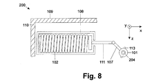
- lever assemblies in an adjustment 200 according to a in FIG. 8 illustrated fourth embodiment of the invention, the pivotally mounted point of the lever 107, which is not coupled to the connecting rod 111, preferably slidably mounted in a slot 113.
- the recording and locking of this position of the lever 107 is preferably carried out as in the pressure roller 101 of the embodiment described above.
- FIG. 9A shown adjusting device 200 according to a fifth embodiment of the invention. Facing away from the pressure roller 101 and the closer spring housing 108 facing surface of a closer housing 109 or spring stop and the end facing the inside of the side wall 115 of the closer housing 109 are at least at one point to each other. Due to the concern, the end of the closer spring housing 108 or spring stop is guided by means of the inside of the side wall 115.
- Preferably again only one adjusting screw 205 is analogous to the above description of an outer side of the closer housing 109 is screwed into the closer spring housing 108 or the spring stop. By rotating the adjusting screw 205, a pivoting of the arrangement is achieved.
- the operative connection between the closing spring 102 and pressure roller 101 is not rigid.
- the operative connection consists of a connecting rod 111 and a lever 107, which are pivotally coupled together.
- the connecting rod 111 and the lever 107 are coupled to the respective end facing away from the pivot with a spring stop or the pressure roller 101.
- the pivot point is preferably formed by means of a guided and lockable in a slot 113 bearing pin 112.
- At least one connecting rod 111 is preferably provided.
- the connecting rod 111 as in FIG. 9D shown, guide holes in the form of slots 113.
- the tab 114 is fixed by means of locking screws 204.
- the shapes of the guide holes determine the displacement path for the tab 114 and thus the displacement of the pressure roller 101 with respect to the Hubkurvenin 103th
- the flap truck 106 may also include only one connecting rod 111.
- a guide of the flap carriage 106 is by means of a slot reached in the tab 114, by means of which the tab surrounds the output shaft 104 or encloses.
- a bearing sleeve is preferably arranged with, for example, a ball, roller or sliding bearing.
- the bearing sleeve has an outer diameter which is substantially equal to an inner dimension of a cavity formed by the slot 113 or a recess, so that the bearing sleeve is guided guided.
- the attachment stopper 207, the tab carriage 106 or the journal 112 to which the pressure roller 101 is attached has a mounting stopper 211 at one end in a direction substantially opposite to the pressing direction.
- the attachment stop 211 is preferably designed like one of the attachment stops 207 described above.
- a side wall 115 has a preferably in the x-coordinate direction extending through hole for pushing through and screwing a screw 212 into the mounting stop 211 on.
- the pressure roller 101 is preferably arranged displaceably in a slot 113 by means of a bearing journal 112. By means of a fastening screw of the bearing pin 112 is locked in the slot 113.
- the slot 113 may have any shape. It is not limited to a straight design and thus to a purely translational displacement of the pressure roller 101.
- the pressure roller 101 can thus be positioned easier and more precise, since no contact forces are to be overcome, which would otherwise be transmitted from the closing spring 102 to the pressure roller 101.
- a locking device 20 is also preferably provided. Because of such a locking device 20, the screw 204, 205, 212 can be fixed in position.
- two guide members 21 are provided, which are preferably received and guided in a slot 113. This may be the slot 113, in which under certain circumstances, the respective screw 204, 205, 212 is added.
- a placement part 22 is placed on the guide parts 21, a placement part 22 is placed.
- the attachment part 22 preferably has passage openings which extend in the direction of the respective guide part 21.
- the guide parts 21 each have at least one attachment opening, preferably in the form of a threaded bore.
- a fastening screw 23 is screwed from a guide parts 21 facing away from the side of the Aufjobeils 22 through a through hole into a respective threaded hole. It is of course any other type of non-positive and / or positive connection between Aufforceeil 22 and guide members 21 possible.
- the Aufmeneil 22 has on a screw 204, 205, 212 facing side at the point where it meets the screw 204, 205, 212, a recess.
- the recess has a shape that is complementary to the shape of the portion of the screw 204, 205, 212 that is received by the recess.
- a positive connection between screw 204, 205, 212 and attachment part 22 is achieved. Due to the screwing with the guide parts 21 thus the screw 204, 205, 212 is securely fixed in its rotational position.
- the screw 204, 205, 212 is further displaceable in the slot 113. A Movement of the pressure roller 101 due to a rotation of the Hubkurvenement 103 is thus still guaranteed.
- the guide parts 21 are omitted. Instead, the fastening screws are screwed into the respective wall, through which the screw 204, 205, 212 is guided.
- the adjusting devices 200 according to Figures 3 . 4 . 9A and 9B are readily according to door closer 100 according to FIGS. 2A-3B applicable.
- the adjusting devices 200 according to FIGS. 7A and 7B are with a door closer 100 according to FIGS. 2A-2C combined.
- the adjusting device 200 is in particular for door closer 100 according to FIGS. 3A and 3B suitable while the adjusting 200 according to FIG. 7C for a door closer 100 according to Figure 2C is predestined.
- the adjusting device 200 according to FIG. 9D is especially for door closers according to FIGS. 2A and 2B suitable.
- the spring mounting of the pressure roller 101 can be combined with the adjustment devices 200 and door closers 100 described herein.
- the locking devices 10 according to Figures 11A and 11B are applicable to all adjustment screws 205 described herein.
- the adjusting screws 205 are not limited to the illustrated hexagon screws.
- the recess of the Aufmeneils 12 may have any complementary shape of the adjusting screw 205 used in each case. If countersunk screws are used, for example, whose heads are flush in the screw-in state, the mounting part 12 has a projection in complementary form of the head of the countersunk screw instead of a recess. For example, if it is a Phillips countersunk screw, the protrusion has the shape similar to the head of a Phillips screwdriver.
Abstract
Description
Die Erfindung betrifft einen auf einem Nockenmechanismus basierenden Türschließer.The invention relates to a cam mechanism based on a door closer.
Türschließer mit Nockenmechanismus weisen typischerweise eine auf einer Abtriebswelle drehfest angeordnete Hubkurvenscheibe auf, die eine Ablauffläche aufweist, auf der eine Andrückrolle aufgrund einer Schließerfeder angepresst abrollt.Door closers with cam mechanism typically have a Hubkurvenscheibe rotatably mounted on an output shaft, which has a drainage surface on which a pressure roller unrolled pressed due to a closing spring.
Durch die Form der Ablauffläche wird der Verlauf des an dem angetriebenen Drehflügel anliegenden Drehmoments während einer Schließbewegung, d. h. die resultierende Drehmomentkurve, bestimmt.Due to the shape of the drainage surface, the course of the torque applied to the driven rotary vane during a closing movement, i. H. the resulting torque curve is determined.
Die Hubkurvenscheibe kann in Richtung einer Längserstreckung der Abtriebswelle des Türschließers gesehen eine symmetrische oder asymmetrische Querschnittsform aufweisen.The Hubkurvenscheibe seen in the direction of a longitudinal extension of the output shaft of the door closer may have a symmetrical or asymmetrical cross-sectional shape.
Die Andrückrolle ist so gelagert, dass sie sich auf die Hubkurvenscheibe zu und von ihr weg bewegen kann. Die Bewegung erfolgt in Richtung zur Rotationsachse der Abtriebswelle hin und von ihr weg.The pressure roller is mounted so that it can move on the Hubkurvenscheibe to and from her. The movement takes place in the direction of the axis of rotation of the output shaft and away from it.
Die Drehmomentkurve ist durch die Form der jeweiligen Ablauffläche der Hubkurvenscheibe vorgegeben. Dies bedeutet, dass die Hubkurvenscheibe für jeden Einsatzfall speziell ausgebildet, d. h. konstruiert werden muss,The torque curve is determined by the shape of the respective running surface of the Hubkurvenscheibe. This means that the cam disc must be specially designed, ie designed, for each application.
Im Querschnitt symmetrisch ausgebildete Hubkurvenscheiben bewirken bei Gleitschienen-Betrieb eine andere Drehmomentkurve als bei einem Normal- oder Scherengestänge sowohl im Betrag als auch im Verlauf.In cross-section symmetrically shaped Hubkurvenscheiben cause slide rail operation a different torque curve than in a normal or scissor linkage both in magnitude and in the course.
Um ein und denselben Türschließer für beide Betriebsarten einsetzen zu können, müssen die Drehmomentkurven jedoch im Wesentlichen übereinstimmen.However, in order to use one and the same door closer for both modes of operation, the torque curves must be substantially the same.
Zu diesem Zweck wurden asymmetrische Hubkurvenscheiben entwickelt, deren zwei Ablaufflächenhälften auf jeweils eine Betriebsart hin ausgelegt sind. Der durch die Form der Ablaufflächen definierte Verlauf der jeweiligen Drehmomentkurve ist nicht veränderbar.For this purpose, asymmetric cam discs have been developed whose two drainage surface halves are designed for one operating mode. The course of the respective torque curve defined by the shape of the run-off surfaces can not be changed.
Soll nun eine mit einem Türschließer versehene Tür mit einer Brandschutzfunktion versehen werden, sind in einem vorbestimmten ersten Öffnungswinkel-Bereich (ca. 0° - 4°) eines Drehflügels und in einem vorbestimmten zweiten Öffnungswinkel-Bereich (ca. 88° - 92°) des Drehflügels Drehmomente nur innerhalb vorbestimmter Grenzen zulässig. Außerdem gibt es ein minimales Drehmoment, das über den gesamten Öffnungswinkel-Bereich des Drehflügels nicht unterschritten werden darf.If now a door provided with a door closer door are provided with a fire protection function, are in a predetermined first opening angle range (about 0 ° - 4 °) of a rotary wing and in a predetermined second opening angle range (about 88 ° - 92 °) of the rotary vane torques permitted only within predetermined limits. In addition, there is a minimum torque that must not be exceeded over the entire opening angle range of the rotary wing.
Die einzig bekannte Möglichkeit, das Drehmoment am Drehflügel zu verändern, sind Mechanismen zur Einstellung der Vorspannung der Schließerfeder. Solche Mechanismen umfassen zumeist eine Einstellschraube, mittels der die Position eines Schließerfederanschlags verändert werden kann. Damit lässt sich die Größe des Drehmoments in einem im Wesentlichen konstanten Verhältnis verändern. Die Form der Drehmomentkurve bleibt unverändert.The only known way to change the torque on the rotary wing are mechanisms for adjusting the bias of the closing spring. Such mechanisms usually comprise an adjusting screw by means of which the position of a closer spring stop can be changed. Thus, the size of the torque can be changed in a substantially constant ratio. The shape of the torque curve remains unchanged.
Sind ein Drehmoment bei einem Öffnungswinkel von 0°, d. h, bei geschlossenem Drehflügel, zu hoch und ein Enddrehmoment, d. h. ein Drehmoment bei einem maximalen Öffnungswinkel von beispielsweise 90 - 100°, nur geringfügig größer als ein zulässiges minimales Drehmoment, könnte mittels einer Verstellung der Schließerfeder-Vorspannung zwar das Drehmoment bei einem Öffnungswinkel von 0° verringert werden, gleichzeitig würde aber das Enddrehmoment unter das zulässige minimale Drehmoment fallen. Ein Umstellen auf eine Brandschutzfunktion wäre somit unmöglich. Eine Ersetzung eines Türschließers durch einen komplett neuen führt zu enormen Kosten.Are a torque at an opening angle of 0 °, d. h, with the revolving wing closed, too high and a final torque, d. H. a torque at a maximum opening angle of for example 90-100 °, only slightly larger than a permissible minimum torque, could be reduced by means of an adjustment of the closing spring bias while the torque at an opening angle of 0 °, but at the same time the final torque below the allowable minimal torque fall. Switching to a fire protection function would therefore be impossible. Replacing a door closer with a completely new one adds up to enormous costs.
Aufgabe der Erfindung ist es, einen Türschließer zu schaffen, der kostengünstig an den jeweiligen Einsatzfall angepasst hergestellt bzw. im Montagezustand selbst an den jeweiligen Einsatzfall angepasst oder umgestellt werden kann.The object of the invention is to provide a door closer, which can be manufactured inexpensively adapted to the particular application or even adapted or converted in the assembled state to the particular application.
Die Aufgabe wird durch den Gegenstand des Patentanspruchs 1 gelöst. Vorteilhafte Weiterbildungen sind in den Unteransprüchen angegeben.The object is solved by the subject matter of
Erfindungsgemäß weist ein Türschließer eine Andrückrolle, die auf einer Hubkurvenscheibe des Türschließers angepresst abrollt. Die Hubkurvenscheibe ist auf einer Abtriebswelle drehfest angeordnet. Die Andrückrolle ist in Bezug auf einen axialen Mittelpunkt der Abtriebswelle so angeordnet, dass die Andrückrolle bei einem Öffnen oder Schließen eines mit der Abtriebswelle gekoppelten Drehflügels entlang einer Bahn bewegt wird. Dadurch, dass die Bahn an dem axialen Mittelpunkt der Abtriebswelle vorbeiläuft, und aufgrund der Gestaltung der Ablauffläche der Hubkurvenscheibe liegt bei einem jeweiligen Öffnungswinkel des Drehflügels bei verschiedenen Betriebsarten des Türschließers an der Abtriebswelle jeweils ein sehr ähnliches oder identisches Drehmoment an. D. h. bei einer Betriebsart wird ein Verlauf eines am Drehflügel anliegenden, vom Öffnungswinkel des Drehflügels abhängiger Drehmomentverlauf erzielt, der identisch oder sehr ähnlich einem Drehmomentverlauf bei einer anderen Betriebsart ist.According to the invention, a door closer has a pressure roller, which rolls pressed against a cam disc of the door closer. The Hubkurvenscheibe is arranged rotatably on an output shaft. The pressure roller is arranged with respect to an axial center of the output shaft so that the pressure roller is moved along a path upon opening or closing of a coupled with the output shaft rotary vane. Characterized in that the web passes by the axial center of the output shaft, and due to the design of the running surface of Hubkurvenscheibe is at a respective opening angle of the rotary vane at different modes of the door closer to the output shaft in each case a very similar or identical torque. Ie. in one mode a curve of a voltage applied to the rotary vane, dependent on the opening angle of the rotary vane torque curve is achieved, which is identical or very similar to a torque curve in another mode.
Der Drehmomentverlauf ist dabei eine Kennlinie eines an der Abtriebswelle des Türschließers anliegenden Drehmoments in Abhängigkeit vom Öffnungswinkel des Drehflügels.The torque curve is a characteristic of a voltage applied to the output shaft of the door closer torque in dependence on the opening angle of the rotary wing.
Der Vorteil ist, dass nicht nur das Drehmoment im Verhältnis veränderbar ist, sondern es ferner möglich ist, die Form der Drehmomentkurve während einer Bewegung, d. h. einer Schließbewegung eines Drehflügels, trotz Einsatzes einer Hubkurvenscheibe mit ein und derselben Form an den jeweiligen Einsatzfall anzupassen.The advantage is that not only is the torque variable in proportion, but it is also possible to change the shape of the torque curve during a movement, i. H. a closing movement of a rotary wing, despite using a Hubkurvenscheibe with one and the same shape to adapt to the particular application.
Dadurch ist ein einziger Türschließer in verschiedenen Betriebsarten einsetzbar. Diese Betriebsarten umfassen erfindungsgemäß GleitschienenBetrieb und Normal- bzw. Scherengestänge-Betrieb und vorzugsweise zusätzlich Parallelgestänge-Betrieb.As a result, a single door closer can be used in different modes. According to the invention, these operating modes include slide rail operation and normal or scissors linkage operation, and preferably additionally parallel linkage operation.
Es hat sich gezeigt, dass aufgrund der Neuanordnung der Andrückrolle die Drehmomentkurven bei Gleitschienen-Betrieb und bei Normalgestänge-Betrieb insbesondere bei Nutzung einer symmetrisch gestalteten Hubkurvenscheibe aneinander angeglichen werden können.It has been shown that due to the rearrangement of the pressure roller, the torque curves in slide rail operation and normal rod operation, especially when using a symmetrically designed Hubkurvenscheibe can be matched to each other.
Die beschriebene Drehmomentkurven-Angleichung ergibt sich insbesondere bei einer Sturzmontage des erfindungsgemäßen Türschließers bei Gleitschienen-Betrieb auf einer Bandgegenseite oder bei Normalgestänge-Betrieb auf einer Bandseite. Die gleiche Wirkung ergibt sich insbesondere bei einer Türblattmontage des erfindungsgemäßen Türschließers bei Gleitschienen-Betrieb auf der Bandseite oder bei Normalgestänge-Betrieb auf der Bandgegenseite.The described torque curve approximation results in particular in a lintel mounting of the door closer according to the invention in slide rail operation on a tape opposite side or in normal linkage operation on a hinge side. The same effect results in particular in a door leaf assembly of the door closer according to the invention Sliding rail operation on the belt side or in normal linkage operation on the opposite side of the belt.
Zudem ist eine Anpassung an verschiedene EN-Klassen möglich. D. h. ein und derselbe Türschließer kann für verschiedenartige Schließszenarien und mit verschiedenen Drehflügelgewichten verwendet werden, was weniger verschiedenartig ausgebildete Türschließer erforderlich macht. Dies führt zu einer Senkung von Herstellungskosten.In addition, adaptation to different EN classes is possible. Ie. one and the same door closer can be used for various closing scenarios and with different blade weights, which requires less diversely designed door closers. This leads to a reduction in manufacturing costs.
Zudem ist es möglich, nicht nur den Grad des Drehmomentanstiegs zu verändern sondern gegebenenfalls sogar den Anstieg so zu verändern, dass das Drehmoment beispielsweise zu Beginn nicht abfällt sondern (von einem geringeren Drehmoment bei einem Öffnungswinkel von 0° an) ansteigt.In addition, it is possible to change not only the degree of torque increase but possibly even to change the increase so that the torque, for example, does not drop at the beginning but increases (from a lower torque at an opening angle of 0 °).
Außerdem kann durch solch eine Verstellung ein Sturzausgleich erfolgen, sodass eine Montage sowohl auf Bandseite als auch auf Bandgegenseite möglich ist. Ferner sind derartig ausgebildete Türschließer bei verschiedenen Türgeometrien einsetzbar.In addition, can be done by such an adjustment, a fall compensation, so that a mounting on both the hinge side and on the opposite hinge side is possible. Furthermore, such trained door closers can be used with different door geometries.
Sind die Abtriebswelle und das Gehäuse des erfindungsgemäßen Türschließers so gestaltet, dass die Abtriebswelle an beiden Enden mit einem Drehflügel wirkverbunden werden kann, ist der Türschließer ferner sowohl an DIN-rechten als auch an DIN-linken Drehflügeltüren einsetzbar. Dazu weist das Gehäuse im Bereich der Antriebswellen-Enden jeweils eine Durchgangsöffnung auf, die ggf, mittels einer Abdeckkappe versehen ist, sodass das nicht verwendete Ende der Abtriebswelle nach außen verdeckt ist.Are the output shaft and the housing of the door closer according to the invention designed so that the output shaft can be operatively connected at both ends with a rotary wing, the door closer is also applicable to both DIN-right and DIN-left swing doors. For this purpose, the housing in the region of the drive shaft ends in each case has a passage opening, which is optionally provided by means of a cover cap, so that the unused end of the output shaft is concealed to the outside.
Ferner kann vorgesehen sein, dass die Andrückrolle in Bezug auf die Hubkurvenscheibe in ihrer Position nicht festgelegt ist. D. h. bei einer Rotation der Hubkurvenscheibe bewegt diese die Andrückrolle bis zu einer vorbestimmten Position mit. Die erreichte Position entspricht dann der Position, bei der die gewünschte Drehmomentkurve erzielt wird. Vorzugsweise erfolgt die Verstellung bei einer symmetrischen Hubkurvenscheibe in Bezug auf deren Symmetrieachse. Dies kann dadurch erfolgen, dass die Andrückrolle in einer Richtung quer oder in einem Winkel zwischen 0° und weniger als 90° zu der vorbeschriebenen Bewegungsbahn der Andrückrolle verschiebbar angeordnet ist.Furthermore, it can be provided that the pressure roller is not fixed in relation to the Hubkurvenscheibe in their position. Ie. during a rotation of the Hubkurvenscheibe this moves the pressure roller to a predetermined position. The position reached then corresponds to the position at which the desired torque curve is achieved. Preferably, the adjustment takes place in a symmetrical Hubkurvenscheibe with respect to the axis of symmetry. This can be done by the pressure roller is arranged displaceably in a direction transversely or at an angle between 0 ° and less than 90 ° to the above-described movement path of the pressure roller.
Zusätzlich ist erfindungsgemäß vorgesehen, die Hubkurvenscheibe vorzuverdrehen. Dadurch ist es möglich, das Drehmoment bei einem Öffnungswinkel von 0° in den vorgenannten Betriebsarten aneinander anzugleichen.In addition, the invention provides, vorzuverdrehen the Hubkurvenscheibe. This makes it possible to match the torque at an opening angle of 0 ° in the aforementioned modes to each other.
Zusätzlich hat es sich beim Normalgestänge als vorteilhaft erwiesen, den Abstand des axialen Mittelpunkts der Abtriebswelle des Türschließers zum Rotationspunkt eines Drehflügels und/oder den Abstand des axialen Mittelpunkts der Abtriebswelle des Türschließers zum Anlenkpunkt des Normalgestänges am Drehflügel zu variieren. Mit größer werdendem Abstand zum Rotationspunkt des Drehflügels verändern sich der maximale Öffnungswinkel und die Hebelwirkung. Aufgrund dieser Variationen ist es möglich, die Drehmomente in einem vorbestimmten Verhältnis zu verändern. Beispielsweise können das Verhältnis von Drehmoment bei einem Öffnungswinkel von 0° zu Enddrehmoment und aufgrund der Verstellung des maximalen Öffnungswinkels die Drehmomentkurve verändert werden. Besonders vorteilhaft hat sich erwiesen, wenn der Abstand zum Anlenkpunkt des Normalgestänges gleich oder größer als der Abstand zum Rotationspunkt des Drehflügels ist.In addition, it has proven to be advantageous in the normal linkage to vary the distance of the axial center of the output shaft of the door closer to the rotation point of a rotary wing and / or the distance of the axial center of the output shaft of the door closer to the articulation point of the normal linkage on the rotary wing. With increasing distance to the rotation point of the rotary wing, the maximum opening angle and the leverage change. Due to these variations, it is possible to change the torques in a predetermined ratio. For example, the ratio of torque at an opening angle of 0 ° to end torque and due to the adjustment of the maximum opening angle, the torque curve can be changed. It has proved particularly advantageous if the distance to the articulation point of the normal linkage is equal to or greater than the distance to the rotation point of the rotary vane.
Erfindungsgemäß ist die Hubkurvenscheibe symmetrisch ausgebildet und hat vorzugsweise eine herzförmige Querschnittsfläche. Dies hat Kostenvorteile im Vergleich zu einer asymmetrischen Hubkurvenscheibe. Zum einen ist die Form nur einer Hälfte der Ablauffläche der Hubkurvenscheibe zu berechnen und damit zu konstruieren. Ferner sind weniger unterschiedliche Ablaufflächenformen erforderlich, was die Vielfalt an einzusetzenden Hubkurvenscheiben und damit an Herstellungs-Werkzeugen reduziert.According to the Hubkurvenscheibe is symmetrical and preferably has a heart-shaped cross-sectional area. This has cost advantages compared to an asymmetric cam disc. On the one hand, the shape of only one half of the running surface of the Hubkurvenscheibe to calculate and thus construct. Furthermore, fewer different drain surface shapes are required, which reduces the variety of Hubkurvenscheiben to be used and thus to manufacturing tools.
Alternativ oder zusätzlich ist der Türschließer erfindungsgemäß so gestaltet, dass die Richtung der Bewegungsbahn der Andrückrolle im Montagezustand des Türschließers eingestellt werden kann. Dadurch ist es möglich, den Türschließer auch im Montagezustand, d. h. vor Ort, noch an etwaige Besonderheiten des Öffnungs- bzw. Schließvorgangs anzupassen. Zudem ist es dadurch möglich, den Türschließer auch im Nachhinein noch mit einer neuen Funktion zu versehen oder beispielsweise von Gleitschienen-Betrieb auf Normalgestänge- oder Parallelgestänge-Betrieb oder umgekehrt umzustellen.Alternatively or additionally, the door closer according to the invention is designed so that the direction of the movement path of the pressure roller in the assembled state of the door closer can be adjusted. This makes it possible, the door closer in the assembled state, d. H. on site, still to adapt to any peculiarities of the opening or closing process. In addition, this makes it possible to provide the door closer with a new function in retrospect or, for example, switch from slide rail operation to normal linkage or parallel linkage operation or vice versa.
D. h. ein und derselbe Türschließer ist universell einsetzbar. Die Herstellungskosten werden gesenkt, da mit weniger Typen von Türschließern eine Vielfalt an Automatikfunktionen, wie beispielsweise Brandschutzfunktion, realisiert werden kann.Ie. one and the same door closer is universally applicable. The manufacturing costs are reduced because with fewer types of door closers, a variety of automatic functions, such as fire protection function, can be realized.
Alternativ oder zusätzlich ist vorgesehen, die Anordnung bestehend zumindest aus einer Andrückrolle und einer Schließerfeder rotierbar und arretierbar zu lagern, wobei der Rotationspunkt nicht der axiale Mittelpunkt der Abtriebswelle des Türschließers ist.Alternatively or additionally, it is provided to mount the arrangement consisting of at least one pressure roller and a closing spring rotatable and lockable, wherein the rotation point is not the axial center of the output shaft of the door closer.
Zusätzlich oder anstelle der Rotationslagerung kann die Anordnung insgesamt verschiebbar gelagert sein.In addition or instead of the rotary bearing arrangement, the arrangement can be mounted as a whole displaceable.
Weitere Merkmale und Vorteile der Erfindung ergeben sich aus der nachfolgenden Beschreibung bevorzugter Ausführungsbeispiele.Further features and advantages of the invention will become apparent from the following description of preferred embodiments.
Es zeigen:
- Figur 1A:
- ein Diagramm, das den Verlauf eines Kraftübersetzungsverhältnisses einer Hubkurvenscheibe bei einem herkömmlichen Nockenmechanismus in Abhängigkeit von einem Öffnungswinkel zeigt,
- Figur 1B:
- zwei Diagramme, die den Verlauf des Kraftübersetzungsverhältnisses bzw. eines Drehmoments in Abhängigkeit vom Öffnungswinkel bei einem herkömmlichen Nockenmechanismus im Gleitschienen-Betrieb zeigen,
- Figur 1C:
- zwei Diagramme, die den Verlauf des Kraftübersetzungsverhältnisses bzw. des Drehmoments in Abhängigkeit vom Öffnungswinkel bei einem herkömmlichen Nockenmechanismus im Normalgestänge-Betrieb zeigen,
- Figur 1D:
- zwei Diagramme, die Drehmomentverläufe beim Öffnen und Schließen eines Drehflügels bei einem herkömmlichen Nockenmechanismus zeigen,
- Figur 1E:
- zwei Diagramme, die Drehmomentverläufe beim Öffnen und Schließen eines Drehflügels bei einem Nockenmechanismus zeigen, wobei die Andrückrolle erfindunggemäß versetzt ist,
- Figur 1F:
- ein Diagramm, das Verläufe von Drehmomenten in Abhängigkeit vom Öffnungswinkel bei einem Nockenmechanismus im Normalgestänge-Betrieb bei verschiedenen Positionen der Andrückrolle zeigt,
- Figuren 2A - 2C:
- einen Türschließer mit einer Hubkurvenscheiben-Anordnung gemäß einer ersten Ausführungsform der Erfindung in verschiedenen Varianten,
- Figuren 3A, 3B:
- einen Türschließer mit einer Hubkurvenscheiben-Anordnung gemäß einer zweiten Ausführungsform der Erfindung in verschiedenen Varianten,
- Figur 4:
- einen Türschließer mit einer Hubkurvenscheiben-Anordnung gemäß einer dritten Ausführungsform der Erfindung,
- Figur 5:
- einen Türschließer mit einer Hubkurvenscheiben-Anordnung gemäß einer vierten Ausführungsform der Erfindung,
- Figur 6:
- eine Vorrichtung zun Einstellen der Bewegungsrichtung einer Andrückrolle in Bezug auf eine Hubkurvenscheibe gemäß einer ersten Ausführungsform der Erfindung,
- Figuren 7A - 71:
- eine Vorrichtung zum Einstellen der Bewegungsrichtung einer Andrückrolle in Bezug auf eine Hubkurvenscheibe gemäß einer zweiten Ausführungsform der Erfindung in verschiedenen Varianten,
- Figur 8:
- eine Vorrichtung zum Einstellen der Bewegungsrichtung einer Andrückrolle in Bezug auf eine Hubkurvenscheibe gemäß einer vierten Ausführungsform der Erfindung,
- Figuren 9A - 9D:
- eine Vorrichtung zum Einstellen der Bewegungsrichtung einer Andrückrolle in Bezug auf eine Hubkurvenscheibe gemäß einer fünften Ausführungsform der Erfindung in verschiedenen Varianten,
- Figur 10:
- einen Mechanismus zum Lösen einer Andrückrolle von einer Hubkurvenscheibe gemäß einer Ausführungsform der Erfindung und
- Figuren 11A, 11B:
- Vorrichtungen zum Arretieren einer Einstellschraube gemäß einer Ausführungsform der Erfindung.
- FIG. 1A
- a diagram showing the curve of a power transmission ratio of a Hubkurvenscheibe in a conventional cam mechanism in response to an opening angle,
- FIG. 1B
- two diagrams showing the course of the power transmission ratio or a torque as a function of the opening angle in a conventional cam mechanism in slide rail operation,
- FIG. 1C:
- two diagrams showing the course of the power transmission ratio or the torque as a function of the opening angle in a conventional cam mechanism in the normal rod operation,
- FIG. 1D:
- two diagrams showing torque curves when opening and closing a rotary vane in a conventional cam mechanism,
- FIG. 1E:
- two diagrams showing torque curves when opening and closing a rotary vane in a cam mechanism, wherein the pressure roller is offset according to the invention,
- FIG. 1F:
- a diagram showing curves of torques as a function of the opening angle in a cam mechanism in normal linkage operation at different positions of the pressure roller,
- FIGS. 2A-2C:
- a door closer with a Hubkurvenscheiben arrangement according to a first embodiment of the invention in different variants,
- FIGS. 3A, 3B:
- a door closer with a Hubkurvenscheiben arrangement according to a second embodiment of the invention in different variants,
- FIG. 4:
- a door closer with a Hubkurvenscheiben arrangement according to a third embodiment of the invention,
- FIG. 5:
- a door closer with a Hubkurvenscheiben arrangement according to a fourth embodiment of the invention,
- FIG. 6:
- a device for adjusting the direction of movement of a pressure roller with respect to a Hubkurvenscheibe according to a first embodiment of the invention,
- FIGS. 7A-71:
- a device for adjusting the direction of movement of a pressure roller with respect to a Hubkurvenscheibe according to a second embodiment of the invention in various variants,
- FIG. 8:
- a device for adjusting the direction of movement of a pressure roller with respect to a Hubkurvenscheibe according to a fourth embodiment of the invention,
- FIGS. 9A-9D:
- a device for adjusting the direction of movement of a pressure roller with respect to a Hubkurvenscheibe according to a fifth embodiment of the invention in various variants,
- FIG. 10:
- a mechanism for releasing a pressure roller from a Hubkurvenscheibe according to an embodiment of the invention and
- FIGS. 11A, 11B:
- Devices for locking an adjusting screw according to an embodiment of the invention.
In
Wird solch ein Nockenmechanismus mit einer Gleitschiene kombiniert, ergibt sich eine Kraftübersetzungskurve gemäß dem linken Diagramm in
Wird derselbe Nockenmechanismus mit einem Normalgestänge kombiniert, ergibt sich eine Kraftübersetzungskurve gemäß dem linken Diagramm in
Um zu erreichen, dass die Drehmomentverläufe bei Gleitschienen-Betrieb und bei Normalgestänge-Betrieb mit ein und derselben Hubkurvenscheibe im Wesentlichen gleich oder ähnlich sind und vorzugsweise im Wesentlichen der Drehmomentkurve im Gleitschienen-Betrieb entsprechen, ist vorgesehen, die Andrückrolle außermittig anzuordnen. Dies bedeutet, dass die Andrückrolle in Bezug auf die Hubkurvenscheibe entlang einer Bahn bewegbar ist, bei der eine Bewegungsrichtung der Andrückrolle in jedem Punkt der Bahn nicht den axialen Mittelpunkt der Hubkurvenscheibe schneidet.In order to achieve that the torque curves in slide rail operation and normal rod operation with one and the same cam disc are substantially equal or similar and preferably substantially correspond to the torque curve in slide rail operation, it is provided to arrange the pressure roller off-center. This means, in that the pressure roller is movable with respect to the cam disc along a path in which a direction of movement of the pressure roller does not intersect at any point of the track the axial center of the cam disc.
In
Im Ergebnis sind die Drehmomente M in den genannten Betriebsarten bei einem jeweiligen Öffnungswinkel ϕ identisch oder sehr ähnlich. Vorzugsweise liegt die Differenz der Drehmomentwerte bei einem jeweiligen Öffnungswinkel ϕ in den Betriebsarten zueinander in einem Bereich von maximal 10%, vorzugsweise 5% oder weniger in Bezug auf eines der anliegenden Drehmomente in einer der Betriebsarten. Durch das aneinander Angleichen der Drehmomentkurven ist es ferner erreicht, dass die zum Öffnen eines Drehflügels erforderliche Kraft in den Betriebsarten in etwa gleich ist.As a result, the torques M in the mentioned modes are identical or very similar at a respective opening angle φ. The difference of the torque values at a respective opening angle φ in the operating modes relative to one another preferably lies in a range of at most 10%, preferably 5% or less with respect to one of the applied torques in one of the operating modes. By matching the torque curves, it is also achieved that the force required to open a rotary vane in the operating modes is approximately the same.
Wie beispielhaft in
Bei einer herkömmlichen Anordnung einer Andrückrolle 101, wie links unten in
Eine Versetzung der Andrückrolle, wie in der Mitte unten in
Beim Rotieren der Hubkurvenscheibe 103 entlang des anderen, gemäß
Ein Türschließer 100 gemäß einer ersten Ausführungsform der Erfindung weist, wie in
Die Andrückrolle 101 ist so angeordnet, dass eine durch ihre im Wesentlichen translatorische Bewegung definierte Linie am axialen Mittelpunkt der Abtriebswelle 104 vorbeiläuft.The
Wie in
Alternativ kann die Schließerfeder 102, wie in
Der Laschenwagen 106 kann auch, wie in
Bei einem in
Eine alternative Hebelanordnung ist in
Bei einem in
Ein in
Zusätzlich kann vorgesehen sein, die Andrückrolle 101 bezüglich ihrer Bewegungsrichtung in einem Montagezustand des Türschließers 100, d. h. wenn er zusammengebaut ist, einstellbar auszubilden.In addition, it may be provided that the
Eine Vorrichtung 200 gemäß einer ersten Ausführungsform der Erfindung zum Einstellen der Position einer Andrückrolle 101 in Bezug auf eine Hubkurvenscheibe 103 im Montagezustand des Türschließers 100 ist in
Die Andrückrolle 101 ist mit der Schließerfeder 102 vorzugsweise mittels einer Verbindungsstange 111 wirkverbunden. Die Verbindungsstange 111 ist in einer Führung 105 translatorisch auf die Schließerfeder 102 zu oder von ihr weg bewegbar gelagert.The
Alternativ ist die Verbindungsstange 111 in die Schließerfeder 102 hinein geführt und wird mittels der Schließerfeder 102 translatorisch geführt. In dem Fall kann ein Schließerfedergehäuse 108 entfallen.Alternatively, the connecting
Die Andrückrolle 101 ist an dem der Schließerfeder 102 abgewandten Ende der Verbindungsstange 111 frei rotierbar angebracht.The
Anstelle einer Verschwenkung der genannten Anordnung ist, wie in
Gemäß einer ersten, in
Wird lediglich eine Einstellschraube 205 gedreht, ist in einem gewissen Maß auch eine Verschwenkung der Anordnung möglich.If only one adjusting
Zwei unabhängig verdrehbare Einstellschrauben 205 können unter Umständen eine Verklemmung hervorrufen, sodass ein Verstellen der Anordnung nicht mehr möglich ist.Two independently rotatable adjusting screws 205 may cause a jamming under circumstances, so that an adjustment of the arrangement is no longer possible.
Aus diesem Grund ist gemäß einer zweiten, in
Ist die Andrückrolle 101 in einem Laschenwagen 106 aufgenommen, wie in
Gemäß
Eine fünfte Variante ist in
Alternativ kann anstelle eines Langlochs 113 an der Innenseite des Laschenwagen 106 auch eine in einer x-z-Ebene langlochförmige Ausnehmung ausgebildet sein. D. h. das Langloch ist nicht durch den Laschenwagen 106 hindurchgehend ausgebildet. Der Laschenwagen 106 weist an der Außenseite zumindest an dieser Stelle vorzugsweise eine durchgehende Fläche auf.Alternatively, instead of a
Eine sechste Variante ist eine in
Um eine sichere Verstellung zu gewährleisten, kann ferner vorgesehen sein, die Einstellschraube 205 bei den in
Alternativ oder zusätzlich ist gemäß einer in
An zumindest einer Seite des Laschenwagens 106 ist ein anderes Anschlagteil 209 angeordnet, in dem eine Anschlagfeder 210 in Form einer Druckfeder aufgenommen ist. Bei einem Rotieren der Hubkurvenscheibe 103 in Richtung Anschlagteil 209 wird die Andrückrolle 101 in diese Richtung gedrängt. Aufgrund der sehr starken Kraft der Schließerfeder 102 wird die Andrückrolle 101 nicht mittels der Anschlagfeder 210 in ihre Ausgangsposition zurückgedrängt. Erst bei einem Rückwärtsrotieren der nicht dargestellten Hubkurvenscheibe 103 gelangt die Andrückrolle 101 aufgrund der Form der Ablauffläche der Hubkurvenscheibe 103 und der Kraft der Schließerfeder 102 wieder in ihre Ausgangsposition.On at least one side of the
Das Anschlagteil 209 kann ortsfest an dem Laschenwagen 106 angebracht sein oder, wie in
Gemäß einer in
Zum Anbringen bzw. Abstützen der Einstellschrauben 205 bzw. Arretierungsanschläge 206 können anstelle des Laschenwagens 106 auch Seitenwände 115 eines Schließerfedergehäuses 108 oder Seitenwände 110 eines Schließergehäuses 109 genutzt werden.For attaching or supporting the adjusting
Hinsichtlich der in
Um eine Verschwenkung der Anordnung gemäß
Alternativ ist das Ende des Schließerfedergehäuses 108 oder des Federanschlags, wie in
Alternativ ist, wie in
Bei einem Laschenwagen 106 ist vorzugsweise zumindest eine Verbindungsstange 111 vorgesehen. Gemäß einer anderen Variante der fünften Ausführungsform der Erfindung weist die Verbindungsstange 111, wie in
Der Laschenwagen 106 kann auch nur eine Verbindungsstange 111 umfassen. Eine Führung des Laschenwagens 106 wird mittels eines Langlochs in der Lasche 114 erreicht, mittels dessen die Lasche die Abtriebswelle 104 umgreifen oder umschließt. Auf der Abtriebswelle 104 ist vorzugsweise eine Lagerhülse mit beispielsweise einem Kugel-, Wälz- oder Gleitlager angeordnet. Die Lagerhülse weist einen Außendurchmesser auf, der im Wesentlichen gleich einem Innenmaß eines durch das Langloch 113 gebildeten Hohlraums oder einer Ausnehmung ist, sodass die Lagerhülse geführt gelagert ist.The
In
Die Andrückrolle 101 kann somit einfacher und präziser positioniert werden, da keine Anpresskräfte zu überwinden sind, die sonst von der Schließerfeder 102 auf die Andrückrolle 101 übertragen würden.The
Ist die gewünschte Position einer Schraube 204, 205, 212 erreicht, ist ferner vorzugsweise eine Arretierungsvorrichtung 20 vorgesehen. Aufgrund solch einer Arretierungsvorrichtung 20 ist die Schraube 204, 205, 212 in ihrer Position fixierbar.If the desired position of a
Wie in
Das Aufsetzteil 22 weist auf einer der Schraube 204, 205, 212 zugewandten Seite an der Stelle, an der es auf die Schraube 204, 205, 212 trifft, eine Ausnehmung auf. Die Ausnehmung weist eine Form auf, die komplementär zu der Form des Teils der Schraube 204, 205, 212 ist, die von der Ausnehmung aufgenommen wird. Dadurch wird eine formschlüssige Verbindung zwischen Schraube 204, 205, 212 und Aufsetzteil 22 erreicht. Aufgrund des Verschraubens mit den Führungsteilen 21 wird somit die Schraube 204, 205, 212 in ihrer Verdreh-Position sicher fixiert. Die Schraube 204, 205, 212 ist weiterhin im Langloch 113 verschiebbar. Eine Bewegung der Andrückrolle 101 aufgrund einer Rotation der Hubkurvenscheibe 103 ist somit weiterhin gewährleistet.The
Aufgrund der Verdrehung der Schraube 204, 205, 212 ist bei der in
Ist die Schraube 204, 205, 212 nicht in einem Langloch aufgenommen, entfallen die Führungsteile 21. Anstatt dessen sind die Befestigungsschrauben in die jeweilige Wand eingeschraubt, durch die die Schraube 204, 205, 212 hindurch geführt ist.If the
Die Einstellvorrichtungen 200 gemäß
Die Einstellvorrichtungen 200 gemäß
Die Einstellvorrichtung 200 ist insbesondere für Türschließer 100 gemäß
Die Einstellvorrichtung 200 gemäß
Die Feder-Lagerung der Andrückrolle 101 ist mit den hierin beschriebenen Einstellvorrichtungen 200 und Türschließern 100 kombinierbar.The spring mounting of the
Die in
Die Arretierungsvorrichtungen 10 gemäß
Die Einstellschrauben 205 sind nicht auf die dargestellten Sechskantschrauben beschränkt.The adjusting screws 205 are not limited to the illustrated hexagon screws.
Die Ausnehmung des Aufsetzteils 12 kann jede Komplementärform der jeweils verwendeten Einstellschraube 205 aufweisen. Werden beispielsweise Senkkopfschrauben verwendet, deren Köpfe im Einschraub-Zustand bündig abschließen, weist das Aufsetzteil 12 anstelle einer Ausnehmung einen Vorsprung in Komplementärform des Kopfes der Senkkopfschraube auf. Handelt es sich beispielsweise um eine Kreuzschlitz-Senkkopfschraube, hat der Vorsprung die Form ähnlich dem Kopf eines Kreuzschlitz-Schraubendrehers.The recess of the Aufsetzteils 12 may have any complementary shape of the adjusting
- 2020
- Arretierungsvorrichtunglocking device
- 2121
- Führungsteilguide part
- 2222
- Aufsetzteilfootpad
- 2323
- Befestigungsschraubefixing screw
- 2424
- LanglochLong hole
- 100100
- Türschließerdoor closers
- 101101
- Andrückrollecapstan
- 102102
- Schließerfedercloser spring
- 103103
- Hubkurvenscheibecam disc
- 104104
- Abtriebswelleoutput shaft
- 105105
- Führungguide
- 106106
- Laschenwagencam plate
- 107107
- Hebellever
- 108108
- SchließerfedergehäuseCloser spring housing
- 109109
- Schließergehäusecloser housing
- 110110
- SeitenwandSide wall
- 111111
- Verbindungsstangeconnecting rod
- 112112
- Lagerzapfenpivot
- 113113
- LanglochLong hole
- 114114
- Lascheflap
- 115115
- SeitenwandSide wall
- 200200
- Einstellvorrichtungadjustment
- 201201
- Führungguide
- 202202
- Vorsprunghead Start
- 203203
- Nutgroove
- 204204
- Arretierungsschraubelocking screw
- 205205
- Einstellschraubeadjustment
- 206206
- Arretierungsanschlagarresting stop
- 207207
- Befestigungsanschlagfastening stopper
- 208208
- Anschlagteilstop part
- 209209
- Anschlagteilstop part
- 210210
- Anschlagfederstop spring
- 211211
- Befestigungsanschlagfastening stopper
- 212212
- Schraubescrew
- iNocke i cam
- Kraftübersetzung der HubkurvenscheibePower ratio of Hubkurvenscheibe
- MM
- Drehmomenttorque
- αα
- Winkelangle
- ββ
- Winkelangle
- ϕφ
- Drehflügel-ÖffnungswinkelRotary blade angle
- ee
- Exzentrizitäteccentricity
- RB R B
- Bewegungsrichtung der AndrückrolleDirection of movement of the pressure roller
- xx
- Koordinatenrichtungcoordinate direction
- yy
- Koordinatenrichtungcoordinate direction
- zz
- Koordinatenrichtungcoordinate direction
Claims (17)
Applications Claiming Priority (3)
| Application Number | Priority Date | Filing Date | Title |
|---|---|---|---|
| DE200710002651 DE102007002651B4 (en) | 2007-01-12 | 2007-01-12 | door closers |
| EP07856536.3A EP2122093B1 (en) | 2007-01-12 | 2007-12-11 | Door closer |
| PCT/EP2007/010774 WO2008083805A1 (en) | 2007-01-12 | 2007-12-11 | Door closer |
Related Parent Applications (2)
| Application Number | Title | Priority Date | Filing Date |
|---|---|---|---|
| EP07856536.3A Division EP2122093B1 (en) | 2007-01-12 | 2007-12-11 | Door closer |
| EP07856536.3A Division-Into EP2122093B1 (en) | 2007-01-12 | 2007-12-11 | Door closer |
Publications (3)
| Publication Number | Publication Date |
|---|---|
| EP2725176A2 true EP2725176A2 (en) | 2014-04-30 |
| EP2725176A3 EP2725176A3 (en) | 2014-08-27 |
| EP2725176B1 EP2725176B1 (en) | 2018-09-05 |
Family
ID=39201543
Family Applications (2)
| Application Number | Title | Priority Date | Filing Date |
|---|---|---|---|
| EP07856536.3A Active EP2122093B1 (en) | 2007-01-12 | 2007-12-11 | Door closer |
| EP13005328.3A Active EP2725176B1 (en) | 2007-01-12 | 2007-12-11 | Door closer |
Family Applications Before (1)
| Application Number | Title | Priority Date | Filing Date |
|---|---|---|---|
| EP07856536.3A Active EP2122093B1 (en) | 2007-01-12 | 2007-12-11 | Door closer |
Country Status (6)
| Country | Link |
|---|---|
| US (1) | US8732904B2 (en) |
| EP (2) | EP2122093B1 (en) |
| JP (1) | JP2010515843A (en) |
| CN (1) | CN101573503B (en) |
| DE (1) | DE102007002651B4 (en) |
| WO (1) | WO2008083805A1 (en) |
Families Citing this family (15)
| Publication number | Priority date | Publication date | Assignee | Title |
|---|---|---|---|---|
| US8938912B2 (en) * | 2011-02-22 | 2015-01-27 | Schlage Lock Company Llc | Door actuator |
| CN102242590B (en) * | 2011-06-08 | 2014-03-26 | 合肥美的电冰箱有限公司 | Door closer and refrigerator |
| US9095214B2 (en) * | 2012-11-29 | 2015-08-04 | Mansfield Engineered Components, Inc. | Door closure mechanism for refrigerator or other appliance |
| KR101418581B1 (en) * | 2012-12-03 | 2014-07-10 | (주) 다원에스디에스 | Door closure including unit adding subsidiary force to close door |
| US9187943B2 (en) * | 2013-08-02 | 2015-11-17 | Dmg Mori Seiki Co., Ltd. | Rotary damper |
| DE102013219037C5 (en) * | 2013-09-23 | 2016-12-22 | Geze Gmbh | door closers |
| CA2924872C (en) | 2013-10-18 | 2021-10-26 | Yale Security, Inc. | Apparatus for providing constant torque output from a door closer or operator |
| CA2991660A1 (en) * | 2015-07-23 | 2017-01-26 | Gotthard 3 Mechatronic Solutions AG | Drive for a rotatable wing |
| US11105135B2 (en) | 2015-12-31 | 2021-08-31 | Larson Manufacturing Company Of South Dakota, Llc | Hydraulic door closer with fluid overflow chamber |
| US10370885B1 (en) | 2015-12-31 | 2019-08-06 | Larson Manufacturing Company Of South Dakota | Hydraulic door closer with fluid overflow chamber |
| AU2017287706B2 (en) | 2016-06-27 | 2022-12-01 | D & D Group Pty Ltd | A hinge mechanism and a hinge assembly |
| US11859434B1 (en) | 2017-03-01 | 2024-01-02 | Mansfield Engineered Components, LLC | Dampened hinge for a refrigerator door or other door |
| WO2018234313A1 (en) * | 2017-06-19 | 2018-12-27 | Fritsjurgens Holding B.V. | Pivot door hinge |
| EP3461978A1 (en) * | 2017-09-27 | 2019-04-03 | dormakaba Deutschland GmbH | Design method for designing an outer contour of a closing cam of a door closer, computer program product, closing cam and door closer |
| US11680434B1 (en) | 2020-07-21 | 2023-06-20 | Andersen Corporation | Damped door closer system and method |
Family Cites Families (28)
| Publication number | Priority date | Publication date | Assignee | Title |
|---|---|---|---|---|
| US2752627A (en) * | 1953-02-26 | 1956-07-03 | George W Houlsby Jr | Pivotal door check device |
| US3137888A (en) * | 1962-01-11 | 1964-06-23 | Bommer Spring Hinge Co Inc | Concealed overhead door closer |
| US3246362A (en) * | 1962-01-22 | 1966-04-19 | Jackson Exit Device Corp | Door closer |
| DE1584237C3 (en) * | 1966-11-12 | 1975-02-13 | Vereinigte Baubeschlagfabriken Gretsch & Co Gmbh, 7250 Leonberg | Closer for swing doors |
| FR2093042A6 (en) * | 1970-05-29 | 1972-01-28 | Etude Verriere Appliquee | |
| FR2045128A5 (en) * | 1969-06-04 | 1971-02-26 | Verrieres Appliq Et | |
| US3696462A (en) * | 1971-01-11 | 1972-10-10 | Republic Industries | Combined door checking and door hold open mechanism |
| DE2124194A1 (en) * | 1971-05-15 | 1972-11-30 | Vereinigte Baubeschlagfabriken Gretsch & Co Gmbh, 7250 Leonberg | Door closer |
| DE7126375U (en) | 1971-07-09 | 1971-10-14 | Vereinigte Baubeschlagfabriken Gretsch & Co Gmbh | DOOR CLOSER LOCKING DEVICE |
| US4069544A (en) * | 1977-03-23 | 1978-01-24 | Rixson-Firemark, Inc. | Electrically actuated door holder and release |
| DE2755787A1 (en) | 1977-12-14 | 1979-06-21 | Gartner & Co J | Universal automatic door closer - has closing spring and attenuating device in tandem in housing, with overlapping slide |
| DE2818761A1 (en) * | 1978-04-28 | 1979-11-08 | Ver Baubeschlag Gretsch Co | DOOR CLOSER |
| DE2938445A1 (en) * | 1979-09-22 | 1981-04-16 | Geze Gmbh, 7250 Leonberg | DOOR CLOSER |
| DE3345004A1 (en) * | 1983-12-13 | 1985-06-13 | Dorma-Baubeschlag Gmbh & Co Kg, 5828 Ennepetal | OVERCLOSE |
| GB2261915B (en) | 1991-11-28 | 1996-03-06 | Jebron Ltd | Method of swinging a pivoted door to a selected position and cam and follower for use in the method |
| US5417013A (en) * | 1992-07-10 | 1995-05-23 | Dorma Gmbh + Co. Kg | Overhead door closer with slide rail for concealed installation in door panels or door frames |
| DE4417227C1 (en) * | 1994-05-17 | 1995-12-14 | Gartner & Co J | Door locking device for attachment in the door sill area |
| DE59509402D1 (en) * | 1994-10-28 | 2001-08-16 | Geze Gmbh | drive |
| DE19506220C2 (en) | 1995-02-22 | 1996-12-12 | Dorma Gmbh & Co Kg | Door closer |
| IT251019Y1 (en) * | 2000-03-13 | 2003-11-04 | Fev Italia Archal S R L | AIR DOOR CLOSER PROVIDED WITH PERFECT ROTATION VEHICLES. |
| GB0124376D0 (en) * | 2001-10-11 | 2001-11-28 | Jebron Ltd | Door Closer |
| DE10336074B3 (en) * | 2003-08-06 | 2005-04-14 | Agtatec Ag | Drive for a wing, in particular rotary drive for a door, a window or the like |
| DE10336075B4 (en) | 2003-08-06 | 2007-06-14 | Agtatec Ag | Drive for a wing, in particular rotary drive for a door, a window or the like |
| DE102004002625B4 (en) * | 2004-01-16 | 2012-10-18 | Dorma Gmbh + Co. Kg | door closers |
| ITTO20040288A1 (en) * | 2004-05-05 | 2004-08-05 | Savio Spa | CORNER AND SAFETY DEPARTMENT GROUP AGAINST FALSE MANEUVER FOR METAL DOOR AND FIXED WINDOW FRAMES. |
| DE102004061626B4 (en) | 2004-12-17 | 2008-09-11 | Dorma Gmbh + Co. Kg | Door drive, in particular swing door drive |
| DE102004061628B4 (en) * | 2004-12-17 | 2008-12-04 | Dorma Gmbh + Co. Kg | Door drive, in particular swing door drive |
| DE102004061624C5 (en) * | 2004-12-17 | 2011-02-03 | Dorma Gmbh + Co. Kg | Door drive, in particular revolving door anti-theft |
-
2007
- 2007-01-12 DE DE200710002651 patent/DE102007002651B4/en not_active Revoked
- 2007-12-11 CN CN200780048668.1A patent/CN101573503B/en active Active
- 2007-12-11 WO PCT/EP2007/010774 patent/WO2008083805A1/en active Application Filing
- 2007-12-11 JP JP2009545094A patent/JP2010515843A/en active Pending
- 2007-12-11 US US12/522,881 patent/US8732904B2/en active Active
- 2007-12-11 EP EP07856536.3A patent/EP2122093B1/en active Active
- 2007-12-11 EP EP13005328.3A patent/EP2725176B1/en active Active
Non-Patent Citations (1)
| Title |
|---|
| None |
Also Published As
| Publication number | Publication date |
|---|---|
| EP2122093A1 (en) | 2009-11-25 |
| US20100064472A1 (en) | 2010-03-18 |
| US8732904B2 (en) | 2014-05-27 |
| JP2010515843A (en) | 2010-05-13 |
| CN101573503B (en) | 2014-03-12 |
| DE102007002651A1 (en) | 2008-07-17 |
| CN101573503A (en) | 2009-11-04 |
| EP2725176A3 (en) | 2014-08-27 |
| WO2008083805A1 (en) | 2008-07-17 |
| DE102007002651B4 (en) | 2015-04-30 |
| EP2725176B1 (en) | 2018-09-05 |
| EP2122093B1 (en) | 2018-04-11 |
Similar Documents
| Publication | Publication Date | Title |
|---|---|---|
| EP2122093B1 (en) | Door closer | |
| EP2122097B1 (en) | Drive for the door leaf of a conventional door | |
| EP2841667B1 (en) | Drive for pivoting door | |
| DE102011056961A1 (en) | Drehflügelbetätiger-link arm | |
| EP3045635A1 (en) | Device to support and facilitate the opening and closing of a window or door | |
| DE102009036872B4 (en) | door unit | |
| DE102005008214B3 (en) | Door hinge for motor vehicle, has brake unit with compression unit and brake casing that are connected with hinge pivot, where casing is engaged with inner surface of housing that is connected with column console in torque-proof manner | |
| EP1431497B1 (en) | Free running device for a wing control of a door or window | |
| DE102013100293A1 (en) | Drive unit for door casement, has first energy storage device exerting torque on leaves in first wing opening angle region at specific angle, and second energy storage device exerting opening torque and closing torque on leaves | |
| EP3175068A1 (en) | Fitting arrangement | |
| EP1375803B1 (en) | Door hinge in particular for motor vehicles | |
| DE10031403C2 (en) | Overhead door closer with a slide rail arrangement | |
| WO2012095090A1 (en) | Attachment for swing door actuator | |
| EP2818618B1 (en) | Device for regulating the closing sequence of a two-leaf revolving door assembly | |
| EP0863286B1 (en) | Closer for a door or the like | |
| EP2818619B1 (en) | Device for regulating the closing sequence of a two-leaf revolving door assembly | |
| DE102015000453A1 (en) | Device for assisting and facilitating opening and closing and with a device for regulating a window or a door | |
| EP0943770B1 (en) | Door or window hinge | |
| DE102019100698B4 (en) | door closer damping | |
| EP0709536A1 (en) | Drive | |
| CH705818A2 (en) | Door closer for closing building door, has spring drive to provide closer force and closer shaft coupling to closer arm, where spring drive and closer shaft are coupled with each other by mechanical coupling arrangement | |
| DE102012213782B4 (en) | Displacement assembly for relocating a sash of a window, door or the like relative to a fixed enclosure having a sash-side and a sill-side control | |
| EP2735681A2 (en) | Drive for a leaf of a door or window | |
| EP0976907A2 (en) | Actuator for a vertically slidable closure element | |
| EP1503016A2 (en) | Pivot device |
Legal Events
| Date | Code | Title | Description |
|---|---|---|---|
| PUAI | Public reference made under article 153(3) epc to a published international application that has entered the european phase |
Free format text: ORIGINAL CODE: 0009012 |
|
| 17P | Request for examination filed |
Effective date: 20131112 |
|
| AC | Divisional application: reference to earlier application |
Ref document number: 2122093 Country of ref document: EP Kind code of ref document: P |
|
| AK | Designated contracting states |
Kind code of ref document: A2 Designated state(s): AT BE BG CH CY CZ DE DK EE ES FI FR GB GR HU IE IS IT LI LT LU LV MC MT NL PL PT RO SE SI SK TR |
|
| PUAL | Search report despatched |
Free format text: ORIGINAL CODE: 0009013 |
|
| AK | Designated contracting states |
Kind code of ref document: A3 Designated state(s): AT BE BG CH CY CZ DE DK EE ES FI FR GB GR HU IE IS IT LI LT LU LV MC MT NL PL PT RO SE SI SK TR |
|
| RIC1 | Information provided on ipc code assigned before grant |
Ipc: E05F 3/10 20060101AFI20140721BHEP |
|
| 17P | Request for examination filed |
Effective date: 20150210 |
|
| RBV | Designated contracting states (corrected) |
Designated state(s): AT BE BG CH CY CZ DE DK EE ES FI FR GB GR HU IE IS IT LI LT LU LV MC MT NL PL PT RO SE SI SK TR |
|
| RAP1 | Party data changed (applicant data changed or rights of an application transferred) |
Owner name: DORMA DEUTSCHLAND GMBH |
|
| 17Q | First examination report despatched |
Effective date: 20160721 |
|
| STAA | Information on the status of an ep patent application or granted ep patent |
Free format text: STATUS: EXAMINATION IS IN PROGRESS |
|
| RAP1 | Party data changed (applicant data changed or rights of an application transferred) |
Owner name: DORMAKABA DEUTSCHLAND GMBH |
|
| GRAP | Despatch of communication of intention to grant a patent |
Free format text: ORIGINAL CODE: EPIDOSNIGR1 |
|
| STAA | Information on the status of an ep patent application or granted ep patent |
Free format text: STATUS: GRANT OF PATENT IS INTENDED |
|
| INTG | Intention to grant announced |
Effective date: 20180327 |
|
| GRAS | Grant fee paid |
Free format text: ORIGINAL CODE: EPIDOSNIGR3 |
|
| GRAA | (expected) grant |
Free format text: ORIGINAL CODE: 0009210 |
|
| STAA | Information on the status of an ep patent application or granted ep patent |
Free format text: STATUS: THE PATENT HAS BEEN GRANTED |
|
| AC | Divisional application: reference to earlier application |
Ref document number: 2122093 Country of ref document: EP Kind code of ref document: P |
|
| AK | Designated contracting states |
Kind code of ref document: B1 Designated state(s): AT BE BG CH CY CZ DE DK EE ES FI FR GB GR HU IE IS IT LI LT LU LV MC MT NL PL PT RO SE SI SK TR |
|
| REG | Reference to a national code |
Ref country code: GB Ref legal event code: FG4D Free format text: NOT ENGLISH |
|
| REG | Reference to a national code |
Ref country code: CH Ref legal event code: EP |
|
| REG | Reference to a national code |
Ref country code: AT Ref legal event code: REF Ref document number: 1037998 Country of ref document: AT Kind code of ref document: T Effective date: 20180915 |
|
| REG | Reference to a national code |
Ref country code: IE Ref legal event code: FG4D Free format text: LANGUAGE OF EP DOCUMENT: GERMAN |
|
| REG | Reference to a national code |
Ref country code: DE Ref legal event code: R096 Ref document number: 502007016379 Country of ref document: DE |
|
| REG | Reference to a national code |
Ref country code: NL Ref legal event code: MP Effective date: 20180905 |
|
| REG | Reference to a national code |
Ref country code: LT Ref legal event code: MG4D |
|
| PG25 | Lapsed in a contracting state [announced via postgrant information from national office to epo] |
Ref country code: SE Free format text: LAPSE BECAUSE OF FAILURE TO SUBMIT A TRANSLATION OF THE DESCRIPTION OR TO PAY THE FEE WITHIN THE PRESCRIBED TIME-LIMIT Effective date: 20180905 Ref country code: BG Free format text: LAPSE BECAUSE OF FAILURE TO SUBMIT A TRANSLATION OF THE DESCRIPTION OR TO PAY THE FEE WITHIN THE PRESCRIBED TIME-LIMIT Effective date: 20181205 Ref country code: LT Free format text: LAPSE BECAUSE OF FAILURE TO SUBMIT A TRANSLATION OF THE DESCRIPTION OR TO PAY THE FEE WITHIN THE PRESCRIBED TIME-LIMIT Effective date: 20180905 Ref country code: FI Free format text: LAPSE BECAUSE OF FAILURE TO SUBMIT A TRANSLATION OF THE DESCRIPTION OR TO PAY THE FEE WITHIN THE PRESCRIBED TIME-LIMIT Effective date: 20180905 Ref country code: GR Free format text: LAPSE BECAUSE OF FAILURE TO SUBMIT A TRANSLATION OF THE DESCRIPTION OR TO PAY THE FEE WITHIN THE PRESCRIBED TIME-LIMIT Effective date: 20181206 |
|
| PG25 | Lapsed in a contracting state [announced via postgrant information from national office to epo] |
Ref country code: LV Free format text: LAPSE BECAUSE OF FAILURE TO SUBMIT A TRANSLATION OF THE DESCRIPTION OR TO PAY THE FEE WITHIN THE PRESCRIBED TIME-LIMIT Effective date: 20180905 |
|
| PG25 | Lapsed in a contracting state [announced via postgrant information from national office to epo] |
Ref country code: RO Free format text: LAPSE BECAUSE OF FAILURE TO SUBMIT A TRANSLATION OF THE DESCRIPTION OR TO PAY THE FEE WITHIN THE PRESCRIBED TIME-LIMIT Effective date: 20180905 Ref country code: IT Free format text: LAPSE BECAUSE OF FAILURE TO SUBMIT A TRANSLATION OF THE DESCRIPTION OR TO PAY THE FEE WITHIN THE PRESCRIBED TIME-LIMIT Effective date: 20180905 Ref country code: CZ Free format text: LAPSE BECAUSE OF FAILURE TO SUBMIT A TRANSLATION OF THE DESCRIPTION OR TO PAY THE FEE WITHIN THE PRESCRIBED TIME-LIMIT Effective date: 20180905 Ref country code: PL Free format text: LAPSE BECAUSE OF FAILURE TO SUBMIT A TRANSLATION OF THE DESCRIPTION OR TO PAY THE FEE WITHIN THE PRESCRIBED TIME-LIMIT Effective date: 20180905 Ref country code: IS Free format text: LAPSE BECAUSE OF FAILURE TO SUBMIT A TRANSLATION OF THE DESCRIPTION OR TO PAY THE FEE WITHIN THE PRESCRIBED TIME-LIMIT Effective date: 20190105 Ref country code: NL Free format text: LAPSE BECAUSE OF FAILURE TO SUBMIT A TRANSLATION OF THE DESCRIPTION OR TO PAY THE FEE WITHIN THE PRESCRIBED TIME-LIMIT Effective date: 20180905 Ref country code: ES Free format text: LAPSE BECAUSE OF FAILURE TO SUBMIT A TRANSLATION OF THE DESCRIPTION OR TO PAY THE FEE WITHIN THE PRESCRIBED TIME-LIMIT Effective date: 20180905 Ref country code: EE Free format text: LAPSE BECAUSE OF FAILURE TO SUBMIT A TRANSLATION OF THE DESCRIPTION OR TO PAY THE FEE WITHIN THE PRESCRIBED TIME-LIMIT Effective date: 20180905 |
|
| PG25 | Lapsed in a contracting state [announced via postgrant information from national office to epo] |
Ref country code: SK Free format text: LAPSE BECAUSE OF FAILURE TO SUBMIT A TRANSLATION OF THE DESCRIPTION OR TO PAY THE FEE WITHIN THE PRESCRIBED TIME-LIMIT Effective date: 20180905 Ref country code: PT Free format text: LAPSE BECAUSE OF FAILURE TO SUBMIT A TRANSLATION OF THE DESCRIPTION OR TO PAY THE FEE WITHIN THE PRESCRIBED TIME-LIMIT Effective date: 20190105 |
|
| REG | Reference to a national code |
Ref country code: DE Ref legal event code: R097 Ref document number: 502007016379 Country of ref document: DE |
|
| PLBE | No opposition filed within time limit |
Free format text: ORIGINAL CODE: 0009261 |
|
| STAA | Information on the status of an ep patent application or granted ep patent |
Free format text: STATUS: NO OPPOSITION FILED WITHIN TIME LIMIT |
|
| PG25 | Lapsed in a contracting state [announced via postgrant information from national office to epo] |
Ref country code: DK Free format text: LAPSE BECAUSE OF FAILURE TO SUBMIT A TRANSLATION OF THE DESCRIPTION OR TO PAY THE FEE WITHIN THE PRESCRIBED TIME-LIMIT Effective date: 20180905 |
|
| REG | Reference to a national code |
Ref country code: CH Ref legal event code: PL |
|
| 26N | No opposition filed |
Effective date: 20190606 |
|
| GBPC | Gb: european patent ceased through non-payment of renewal fee |
Effective date: 20181211 |
|
| PG25 | Lapsed in a contracting state [announced via postgrant information from national office to epo] |
Ref country code: LU Free format text: LAPSE BECAUSE OF NON-PAYMENT OF DUE FEES Effective date: 20181211 Ref country code: MC Free format text: LAPSE BECAUSE OF FAILURE TO SUBMIT A TRANSLATION OF THE DESCRIPTION OR TO PAY THE FEE WITHIN THE PRESCRIBED TIME-LIMIT Effective date: 20180905 Ref country code: SI Free format text: LAPSE BECAUSE OF FAILURE TO SUBMIT A TRANSLATION OF THE DESCRIPTION OR TO PAY THE FEE WITHIN THE PRESCRIBED TIME-LIMIT Effective date: 20180905 |
|
| REG | Reference to a national code |
Ref country code: IE Ref legal event code: MM4A |
|
| REG | Reference to a national code |
Ref country code: BE Ref legal event code: MM Effective date: 20181231 |
|
| PG25 | Lapsed in a contracting state [announced via postgrant information from national office to epo] |
Ref country code: FR Free format text: LAPSE BECAUSE OF NON-PAYMENT OF DUE FEES Effective date: 20181231 Ref country code: IE Free format text: LAPSE BECAUSE OF NON-PAYMENT OF DUE FEES Effective date: 20181211 |
|
| PG25 | Lapsed in a contracting state [announced via postgrant information from national office to epo] |
Ref country code: BE Free format text: LAPSE BECAUSE OF NON-PAYMENT OF DUE FEES Effective date: 20181231 |
|
| PG25 | Lapsed in a contracting state [announced via postgrant information from national office to epo] |
Ref country code: LI Free format text: LAPSE BECAUSE OF NON-PAYMENT OF DUE FEES Effective date: 20181231 Ref country code: CH Free format text: LAPSE BECAUSE OF NON-PAYMENT OF DUE FEES Effective date: 20181231 Ref country code: GB Free format text: LAPSE BECAUSE OF NON-PAYMENT OF DUE FEES Effective date: 20181211 |
|
| PG25 | Lapsed in a contracting state [announced via postgrant information from national office to epo] |
Ref country code: MT Free format text: LAPSE BECAUSE OF FAILURE TO SUBMIT A TRANSLATION OF THE DESCRIPTION OR TO PAY THE FEE WITHIN THE PRESCRIBED TIME-LIMIT Effective date: 20180905 |
|
| REG | Reference to a national code |
Ref country code: AT Ref legal event code: MM01 Ref document number: 1037998 Country of ref document: AT Kind code of ref document: T Effective date: 20181211 |
|
| PG25 | Lapsed in a contracting state [announced via postgrant information from national office to epo] |
Ref country code: TR Free format text: LAPSE BECAUSE OF FAILURE TO SUBMIT A TRANSLATION OF THE DESCRIPTION OR TO PAY THE FEE WITHIN THE PRESCRIBED TIME-LIMIT Effective date: 20180905 |
|
| PG25 | Lapsed in a contracting state [announced via postgrant information from national office to epo] |
Ref country code: AT Free format text: LAPSE BECAUSE OF NON-PAYMENT OF DUE FEES Effective date: 20181211 |
|
| PG25 | Lapsed in a contracting state [announced via postgrant information from national office to epo] |
Ref country code: CY Free format text: LAPSE BECAUSE OF FAILURE TO SUBMIT A TRANSLATION OF THE DESCRIPTION OR TO PAY THE FEE WITHIN THE PRESCRIBED TIME-LIMIT Effective date: 20180905 Ref country code: HU Free format text: LAPSE BECAUSE OF FAILURE TO SUBMIT A TRANSLATION OF THE DESCRIPTION OR TO PAY THE FEE WITHIN THE PRESCRIBED TIME-LIMIT; INVALID AB INITIO Effective date: 20071211 |
|
| PGFP | Annual fee paid to national office [announced via postgrant information from national office to epo] |
Ref country code: DE Payment date: 20231214 Year of fee payment: 17 |