EP2725146A1 - Modular base dehumidifier - Google Patents
Modular base dehumidifier Download PDFInfo
- Publication number
- EP2725146A1 EP2725146A1 EP13189081.6A EP13189081A EP2725146A1 EP 2725146 A1 EP2725146 A1 EP 2725146A1 EP 13189081 A EP13189081 A EP 13189081A EP 2725146 A1 EP2725146 A1 EP 2725146A1
- Authority
- EP
- European Patent Office
- Prior art keywords
- plinth
- dehumidifier
- module
- essentially
- longitudinal direction
- Prior art date
- Legal status (The legal status is an assumption and is not a legal conclusion. Google has not performed a legal analysis and makes no representation as to the accuracy of the status listed.)
- Withdrawn
Links
- 238000010276 construction Methods 0.000 claims description 19
- 239000000463 material Substances 0.000 claims description 12
- 239000004575 stone Substances 0.000 claims description 3
- 239000002131 composite material Substances 0.000 claims description 2
- 239000004567 concrete Substances 0.000 claims description 2
- 239000002184 metal Substances 0.000 claims description 2
- 239000004033 plastic Substances 0.000 claims description 2
- 239000002023 wood Substances 0.000 claims description 2
- 230000007704 transition Effects 0.000 claims 1
- 238000007791 dehumidification Methods 0.000 description 3
- 238000000034 method Methods 0.000 description 3
- 238000005516 engineering process Methods 0.000 description 2
- 239000011800 void material Substances 0.000 description 2
- 238000003466 welding Methods 0.000 description 2
- 238000005266 casting Methods 0.000 description 1
- 230000001419 dependent effect Effects 0.000 description 1
- 230000000694 effects Effects 0.000 description 1
- 238000001125 extrusion Methods 0.000 description 1
- 238000005259 measurement Methods 0.000 description 1
- 229920000642 polymer Polymers 0.000 description 1
- 239000013049 sediment Substances 0.000 description 1
- 238000007493 shaping process Methods 0.000 description 1
- 230000006641 stabilisation Effects 0.000 description 1
- 238000011105 stabilization Methods 0.000 description 1
- 238000009423 ventilation Methods 0.000 description 1
- XLYOFNOQVPJJNP-UHFFFAOYSA-N water Substances O XLYOFNOQVPJJNP-UHFFFAOYSA-N 0.000 description 1
Images
Classifications
-
- E—FIXED CONSTRUCTIONS
- E02—HYDRAULIC ENGINEERING; FOUNDATIONS; SOIL SHIFTING
- E02D—FOUNDATIONS; EXCAVATIONS; EMBANKMENTS; UNDERGROUND OR UNDERWATER STRUCTURES
- E02D31/00—Protective arrangements for foundations or foundation structures; Ground foundation measures for protecting the soil or the subsoil water, e.g. preventing or counteracting oil pollution
- E02D31/02—Protective arrangements for foundations or foundation structures; Ground foundation measures for protecting the soil or the subsoil water, e.g. preventing or counteracting oil pollution against ground humidity or ground water
-
- E—FIXED CONSTRUCTIONS
- E02—HYDRAULIC ENGINEERING; FOUNDATIONS; SOIL SHIFTING
- E02D—FOUNDATIONS; EXCAVATIONS; EMBANKMENTS; UNDERGROUND OR UNDERWATER STRUCTURES
- E02D31/00—Protective arrangements for foundations or foundation structures; Ground foundation measures for protecting the soil or the subsoil water, e.g. preventing or counteracting oil pollution
- E02D31/02—Protective arrangements for foundations or foundation structures; Ground foundation measures for protecting the soil or the subsoil water, e.g. preventing or counteracting oil pollution against ground humidity or ground water
- E02D31/025—Draining membranes, sheets or fabric specially adapted therefor, e.g. with dimples
Definitions
- the invention relates to a plinth dehumidifier to be used in connection with plinth and wall construction of buildings to keep these free of humidity and terrain material filled with water, to reduce the risk of damage due to humidity.
- Known plinth dehumidifier constructions may be made of tiles, sheets, or cast elements as a channel- or box-like construction, typically 150-200 mm deep and typically 200-300 mm wide from the plinth.
- the construction may be open upwards or supplied with a grate or plate.
- a plinth dehumidifier which comprises a grate as well as a supporting device, which can be mounted up against a plinth as they are placed on a foundation where the supporting devices are made of an in use largely vertically oriented plate bent in U-shape, which corresponds to the length and width measurements of the grate, and that bent flanges have been provided on the upper and lower sides of the plate.
- This invention is delivered as a finished box-like construction, made of a bent plate and with a bar fixed by welding on the inside for stabilization and support of the grate placed on top of the plinth dehumidifier.
- the plinth dehumidifier is assembled of 2 or more module components and thereby can achieve its final form and application defined up to and during the actual mounting process.
- the module components of the plinth dehumidifier is constructed in such a way that it is possible to build a plinth dehumidifier channel without closed surfaces between each individual plinth dehumidifier and thereby achieve better ventilation and dry-keeping of the plinth.
- Another advantage of the unobstructed passage is that pebbles and other stone material can be distributed more easily and evenly in the channel, if this material is desired.
- the terrain material bordering the plinth dehumidifier will fix this in a vertical direction so that frost, sediment movements and the like will not offset the channel.
- one or more of the module components of the plinth dehumidifier are constructed with a fixation element that can retain a grate or a plate that can be positioned on top of the channel.
- each plinth dehumidifier made with a device that can position a grate or plate on top of it, what is achieved is that the necessary tolerances of grates and plates do not accumulate on long channel constructions to an opening which is visually and practically unacceptable.
- FIG 2 shows the different modules, which the plinth dehumidifier according to the embodiment shown in figure 1 comprises.
- a plinth dehumidifier is in use positioned between a plinth 1 on a building and the terrain surrounding the building so that the longitudinal direction of the plinth dehumidifier essentially runs parallel with the plinth 1.
- the first module of the plinth dehumidifier is a front plate 10 the function of which is to form the shield between the plinth dehumidifier and the terrain, horizontally from the plinth.
- the front plate 10 essentially extends in the longitudinal direction of the plinth dehumidifier.
- the function of front plate 10 can also be to connect and form a distance between two or several other modules.
- the top of front plate 10 is shaped with a flange 10B with two angle-bends as shown in figure 2 in such a way that a grate or plate can be supported here.
- the front plate 10 can have other shapes and projections at the top.
- the front plate is shaped with a horizontal plate construction 10A with direction away from the dehumidifier channel so that the construction is fixed in vertical direction of the terrain material against which the front plate 10 forms a shield.
- the plate construction 10A and the flange 10B on the front plate 10 furthermore have the function to provide the front plate with rigidity and strength relative to the pressure from the terrain material.
- the plate construction 10A may be left out or have a direction in towards the plinth dehumidifier.
- the plinth dehumidifier comprises another module in the form of a connection and end piece 11, the function of which is partly to maintain the distance and shape between plinth and the front plate 10, and partly to form the area of support onto which the other modules are supported, joined and fastened.
- connection and end piece 11 is made of a plate and shaped like a double U, where the first U provides the piece with its strength and stability, and where the legs of the first U extend parallel with the plinth dehumidifier's transverse and vertical directions, respectively.
- the second U stands perpendicularly to the longitudinal direction of the plinth dehumidifier and forms the distance between the plinth 1 and the front plate 10.
- the second U has a surface or a leg section 11C, which in the mounted condition points towards the plinth 1, which has been adapted to support against or attachment to the plinth 1, and which on top has a usually horizontal supporting area 11 E, onto which a grate or plate can be supported.
- the second U has a horizontal area or a middle piece 11 B at the bottom against the terrain below, the function of which is to transfer the load to the terrain that might come from a grate or a plate.
- the connection and end piece is made with a fixation element 11A, which can hold the grate or plate in such a way that it cannot be offset in the plinth dehumidifier's longitudinal direction.
- the fixation element 11A is designed as a vertically placed piece of plate with a slit in which two grates or plates can be assembled and secured.
- first and the second modules may be designed in one piece, e.g. by being bent in one and the same plate.
- the third module is an adaptor element 12, which is predominantly used where the horizontal plinth contour has parallel offsets.
- the adaptor element 12 is made as a box corner section, with two mutually perpendicular sides as well as top and bottom areas.
- the top area supports a grate or plate, the bottom area distributes the load from here to the supporting terrain and the two sides form the connection between these two areas.
- the adaptor element 12 is mainly attached to the connection and end piece 11.
- the fourth module is an endplate 13.
- the endplate is an essentially plane plate which is predominantly used where the plinth dehumidifier is ending towards the terrain.
- the endplate 13 usually has the same dimensions as the total height of the front plate 10 and the nominal width of the plinth dehumidifier from rear edge of the posterior area 11C of the connection and end piece 11 and to the anterior upper vertical area of the front plate - farthest off the connection and end piece 11.
- the endplate 13 is mainly mounted to the connection and end piece 11.
- the fifth module is a blind profile 14.
- the blind section is mainly used where two front plates 10 are mounted perpendicularly to each other and the opening caused by the contours of the front plate 10 may allow terrain material to penetrate into the plinth dehumidifier room.
- the blind profile 14 is constructed as a U-profile, with a length that fits into the vertical offset of the front plate 10 away from the plinth.
- the blind profile 14 is mainly mounted onto the connection and end piece 11.
- each plinth dehumidifier of the plinth dehumidifier channel may have a different number of each of the above mentioned modules.
- a plinth dehumidifier according to the invention in its most simple version comprises a front plate 10 and a connection and end piece 11, respectively, but that a plinth dehumidifier according to the invention nevertheless in principle may comprise one or more of each of the above mentioned modules.
- the plinth dehumidifier may be placed detached at the place of application or be fixed to the foundation or plinth with a suitable connection method.
- the modules may be made of any material with sufficient strength and resistance to weather. Examples hereof are metal, polymers, plastic, composite materials, concrete, and natural inventions such as e.g. stone or wood, or combinations of these materials.
- modules in this example are based on a plate.
- the modules may be constructed by means of casting, extrusion, welding, shaping or combinations of these, just as the modules in that case would be able to take on other shapes and profiles.
- the shape of the plinth dehumidifier may both horizontally and vertically, which means in both the longitudinal direction and height direction, be straight, curved, waved, angular, perpendicular, offset, or wedged.
Landscapes
- Engineering & Computer Science (AREA)
- Life Sciences & Earth Sciences (AREA)
- Environmental & Geological Engineering (AREA)
- Hydrology & Water Resources (AREA)
- General Life Sciences & Earth Sciences (AREA)
- Mining & Mineral Resources (AREA)
- Paleontology (AREA)
- Civil Engineering (AREA)
- General Engineering & Computer Science (AREA)
- Structural Engineering (AREA)
- Drying Of Gases (AREA)
Abstract
Description
- The invention relates to a plinth dehumidifier to be used in connection with plinth and wall construction of buildings to keep these free of humidity and terrain material filled with water, to reduce the risk of damage due to humidity.
- Known plinth dehumidifier constructions may be made of tiles, sheets, or cast elements as a channel- or box-like construction, typically 150-200 mm deep and typically 200-300 mm wide from the plinth.
- The construction may be open upwards or supplied with a grate or plate.
- In the Danish Patent No.
DK 176375 B1 - With the invention it is a desire to provide a plinth dehumidifier of the kind mentioned, which is flexible in use.
- With the invention it is also a desire to provide a plinth dehumidifier of the kind mentioned, which offers better circulation of the air and thereby better dehumidification of the plinth.
- With the invention it is also a desire to provide a plinth dehumidifier which is also fixed vertically to the terrain material.
- With the invention it is also a desire to provide a plinth dehumidifier that can fix a grate or plate along the dehumidification channel, when this plate is positioned on top of the plinth dehumidifier.
- With the invention it is also a desire to provide a plinth dehumidifier which when not mounted only takes up limited space and therefore is easier to transport and store.
- According to the invention the above purposes are achieved with a plinth dehumidifier according to claim 1.
- What is new is that the plinth dehumidifier is assembled of 2 or more module components and thereby can achieve its final form and application defined up to and during the actual mounting process.
- By the possibility of assembling a plinth dehumidifier of 2 or more standard module components so that it matches its placing on a given plinth construction all the way to mounting of the plinth dehumidifier, flexibility in the mounting process is achieved. At the same time simplicity in the specification and equipment of the plinth dehumidifier is achieved, because adjustments are possible all the way to mounting and therefore do not have to be specified ahead of construction of the plinth dehumidification channels in each individual building. Transportation and storage volume will be reduced considerably because the module components of the invention can be packed relatively compact and do not appear in their finished voluminous form until immediately before assembly. Any damage to the product during transportation, storage or assembly can quickly be settled by replacing the damaged module component.
- What is new is that the module components of the plinth dehumidifier is constructed in such a way that it is possible to build a plinth dehumidifier channel without closed surfaces between each individual plinth dehumidifier and thereby achieve better ventilation and dry-keeping of the plinth. Another advantage of the unobstructed passage is that pebbles and other stone material can be distributed more easily and evenly in the channel, if this material is desired.
- Further advantageous embodiments are described in the dependent claims.
- What is new for the form of construction according to claims 4 and 9 is that one or more module components in the plinth dehumidifier are made with a vertical plate in a direction away from the void of the plinth dehumidifier, by which the plinth dehumidifier is also fixed vertically to the terrain material.
- Having one or more module components in the plinth dehumidifier constructed with a horizontal plate construction away from the void of the plinth dehumidifier, the terrain material bordering the plinth dehumidifier will fix this in a vertical direction so that frost, sediment movements and the like will not offset the channel.
- What is new in the embodiment according to claim 6 is that one or more of the module components of the plinth dehumidifier are constructed with a fixation element that can retain a grate or a plate that can be positioned on top of the channel.
- With one or more of the module components in each plinth dehumidifier made with a device that can position a grate or plate on top of it, what is achieved is that the necessary tolerances of grates and plates do not accumulate on long channel constructions to an opening which is visually and practically unacceptable.
-
-
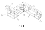
Figure 1 shows an embodiment of a plinth dehumidifier construction which is equipped with a number of plinth dehumidifiers according to this invention in various combinations, which are built into one plinth dehumidifier channel. -
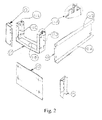
Figure 2 shows an example of module elements of a plinth dehumidifier according to this invention. - In the
figures 1 and2 the construction of the invention is shown. -
Figure 2 shows the different modules, which the plinth dehumidifier according to the embodiment shown infigure 1 comprises. - According to the invention a plinth dehumidifier is in use positioned between a plinth 1 on a building and the terrain surrounding the building so that the longitudinal direction of the plinth dehumidifier essentially runs parallel with the plinth 1.
- The first module of the plinth dehumidifier is a
front plate 10 the function of which is to form the shield between the plinth dehumidifier and the terrain, horizontally from the plinth. Thefront plate 10 essentially extends in the longitudinal direction of the plinth dehumidifier. The function offront plate 10 can also be to connect and form a distance between two or several other modules. The top offront plate 10 is shaped with a flange 10B with two angle-bends as shown infigure 2 in such a way that a grate or plate can be supported here. Alternatively, thefront plate 10 can have other shapes and projections at the top. - At the bottom the front plate is shaped with a horizontal plate construction 10A with direction away from the dehumidifier channel so that the construction is fixed in vertical direction of the terrain material against which the
front plate 10 forms a shield. The plate construction 10A and the flange 10B on thefront plate 10 furthermore have the function to provide the front plate with rigidity and strength relative to the pressure from the terrain material. Alternatively, the plate construction 10A may be left out or have a direction in towards the plinth dehumidifier. - The plinth dehumidifier comprises another module in the form of a connection and end piece 11, the function of which is partly to maintain the distance and shape between plinth and the
front plate 10, and partly to form the area of support onto which the other modules are supported, joined and fastened. - The connection and end piece 11 is made of a plate and shaped like a double U, where the first U provides the piece with its strength and stability, and where the legs of the first U extend parallel with the plinth dehumidifier's transverse and vertical directions, respectively.
- The second U stands perpendicularly to the longitudinal direction of the plinth dehumidifier and forms the distance between the plinth 1 and the
front plate 10. The second U has a surface or a leg section 11C, which in the mounted condition points towards the plinth 1, which has been adapted to support against or attachment to the plinth 1, and which on top has a usually horizontal supporting area 11 E, onto which a grate or plate can be supported. In addition, the second U has a horizontal area or amiddle piece 11 B at the bottom against the terrain below, the function of which is to transfer the load to the terrain that might come from a grate or a plate. On the top of the area or the leg section 11D, which in the assembled state is facing the front plate, the connection and end piece is made with a fixation element 11A, which can hold the grate or plate in such a way that it cannot be offset in the plinth dehumidifier's longitudinal direction. The fixation element 11A is designed as a vertically placed piece of plate with a slit in which two grates or plates can be assembled and secured. - In an alternative embodiment the first and the second modules may be designed in one piece, e.g. by being bent in one and the same plate. The third module is an
adaptor element 12, which is predominantly used where the horizontal plinth contour has parallel offsets. Theadaptor element 12 is made as a box corner section, with two mutually perpendicular sides as well as top and bottom areas. The top area supports a grate or plate, the bottom area distributes the load from here to the supporting terrain and the two sides form the connection between these two areas. Theadaptor element 12 is mainly attached to the connection and end piece 11. - The fourth module is an
endplate 13. The endplate is an essentially plane plate which is predominantly used where the plinth dehumidifier is ending towards the terrain. Theendplate 13 usually has the same dimensions as the total height of thefront plate 10 and the nominal width of the plinth dehumidifier from rear edge of the posterior area 11C of the connection and end piece 11 and to the anterior upper vertical area of the front plate - farthest off the connection and end piece 11. Theendplate 13 is mainly mounted to the connection and end piece 11. - The fifth module is a blind profile 14. The blind section is mainly used where two
front plates 10 are mounted perpendicularly to each other and the opening caused by the contours of thefront plate 10 may allow terrain material to penetrate into the plinth dehumidifier room. The blind profile 14 is constructed as a U-profile, with a length that fits into the vertical offset of thefront plate 10 away from the plinth. The blind profile 14 is mainly mounted onto the connection and end piece 11. - As shown in
figure 1 it is possible by connecting a number of plinth dehumidifiers according to this invention along the plinth 1 of a building to provide a modularly constructed plinth dehumidifier channel, where each plinth dehumidifier of the plinth dehumidifier channel may have a different number of each of the above mentioned modules. - It should be noted that a plinth dehumidifier according to the invention in its most simple version comprises a
front plate 10 and a connection and end piece 11, respectively, but that a plinth dehumidifier according to the invention nevertheless in principle may comprise one or more of each of the above mentioned modules. - The plinth dehumidifier may be placed detached at the place of application or be fixed to the foundation or plinth with a suitable connection method.
- For mutual fixing of the modules in this example and on all items, use of bolts and screw joints is shown. Attachment with clips, rivets, plate hooks, and plate locks are other possible means of attachment.
- The modules may be made of any material with sufficient strength and resistance to weather. Examples hereof are metal, polymers, plastic, composite materials, concrete, and natural inventions such as e.g. stone or wood, or combinations of these materials.
- The design of the modules in this example is based on a plate. Alternatively the modules may be constructed by means of casting, extrusion, welding, shaping or combinations of these, just as the modules in that case would be able to take on other shapes and profiles.
- The shape of the plinth dehumidifier may both horizontally and vertically, which means in both the longitudinal direction and height direction, be straight, curved, waved, angular, perpendicular, offset, or wedged.
Claims (13)
- Plinth dehumidifier which in use is fitted between a plinth (1) of a building and the terrain surrounding the building, characterized in that the plinth dehumidifier is built up of modules and comprises a first module (10) and at least one second module (11), where the first module (10) is a predominantly plate shaped module to shield the plinth dehumidifier relative to the surrounding terrain at least in a longitudinal direction of the plinth dehumidifier, and the at least one other module (11) constitutes an end and connection section of the plinth dehumidifier and extends essentially perpendicularly to the first module's (10) boundary against the terrain in the longitudinal direction of the plinth dehumidifier.
- Plinth dehumidifier according to claim 1, characterized in that the second module essentially is U-shaped with a mid-section (11B) and two leg section (11C, 11 D), where the leg sections essentially extend perpendicularly to and out from opposite ends of the mid-section, where the leg sections are adapted as base for the first module and the plinth, respectively, and where the mid-section essentially extends perpendicularly to the longitudinal direction of the plinth dehumidifier.
- Plinth dehumidifier according to claim 1 or 2, characterized in that the first module (10) comprises a longitudinal essentially L-shaped flange (10B) which is adapted to receive a grate.
- Plinth dehumidifier according to any of the preceding claims, characterized in that the first module (10) comprises an essentially horizontal plate construction (10A), which in the assembled condition of the plinth dehumidifier extends in a direction away from the at least one second module.
- Plinth dehumidifier according to any of the preceding claims, characterized in that the at least one second module (11) comprises a flange (11 E), which is adapted to receive a grate.
- Plinth dehumidifier according to any of the preceding claims, characterized in that the at least one second module (11) comprises a fixation element (11A), which is adapted for fixation of a grate in the plinth dehumidifier's longitudinal direction.
- Plinth dehumidifier according to any of the preceding claims, characterized in that the plinth dehumidifier, in addition, comprises a third module (12), which is adapted for attachment to the at least one second module (11) to thereby increase the length of the mid-section of the at least one second module (11).
- Plinth dehumidifier according to any of the preceding claims, characterized in that the plinth dehumidifier, in addition, comprises a fourth module (13), which is adapted for attachment to the at least one second module (11) to thereby close one end of the plinth dehumidifier.
- Plinth dehumidifier according to claim 8, is characterized in that the fourth module (13) comprises an essentially horizontal plate construction which in the assembled condition of the plinth dehumidifier extends in a direction away from the at least one second module.
- Plinth dehumidifier according to any of the preceding claims, characterized in that the plinth dehumidifier, in addition, comprises a fifth module (14), which is adapted for attachment to the first module (10) and/or the at least one second module (11) in order to close a transition between the first module (10) and an adjoining other first module.
- Plinth dehumidifier according to any of the preceding claims, characterized in that the modules (10, 11, 12, 13, 14) on their surface, which is essentially perpendicular to the longitudinal direction of the plinth dehumidifier, and which covers at least part of the cross sectional area of the plinth dehumidifier, comprise a through going opening which exceeds 5% of the cross sectional area mentioned.
- Plinth dehumidifier according to any of the preceding claims, characterized in that the modules of the plinth dehumidifier are made of a material selected from the group consisting of metal, plastic, concrete, stone, wood, composite materials, or combinations thereof.
- Plinth dehumidifier channel comprising a plurality of plinth dehumidifiers according to any of the claims 1 to 12, where plinth dehumidifiers of the plinth dehumidifier channel bordering each other are connected to each other by means of their respective at least one second module.
Applications Claiming Priority (1)
| Application Number | Priority Date | Filing Date | Title |
|---|---|---|---|
| DKBA201200157 | 2012-10-17 |
Publications (1)
| Publication Number | Publication Date |
|---|---|
| EP2725146A1 true EP2725146A1 (en) | 2014-04-30 |
Family
ID=49578085
Family Applications (1)
| Application Number | Title | Priority Date | Filing Date |
|---|---|---|---|
| EP13189081.6A Withdrawn EP2725146A1 (en) | 2012-10-17 | 2013-10-17 | Modular base dehumidifier |
Country Status (1)
| Country | Link |
|---|---|
| EP (1) | EP2725146A1 (en) |
Cited By (3)
| Publication number | Priority date | Publication date | Assignee | Title |
|---|---|---|---|---|
| US20150233083A1 (en) * | 2014-02-18 | 2015-08-20 | Oldcastle Precast, Inc. | System and method for foundation slab liquid collection and management |
| DK178315B1 (en) * | 2014-12-12 | 2015-11-30 | Duboks Holding Aps | Base Rendering |
| CN118756820A (en) * | 2024-09-06 | 2024-10-11 | 宇杰集团股份有限公司 | Prefabricated house building |
Citations (1)
| Publication number | Priority date | Publication date | Assignee | Title |
|---|---|---|---|---|
| DK176375B1 (en) | 2006-06-16 | 2007-10-15 | Pf Man Holding Aps | Shelf dehumidifier |
-
2013
- 2013-10-17 EP EP13189081.6A patent/EP2725146A1/en not_active Withdrawn
Patent Citations (1)
| Publication number | Priority date | Publication date | Assignee | Title |
|---|---|---|---|---|
| DK176375B1 (en) | 2006-06-16 | 2007-10-15 | Pf Man Holding Aps | Shelf dehumidifier |
Cited By (4)
| Publication number | Priority date | Publication date | Assignee | Title |
|---|---|---|---|---|
| US20150233083A1 (en) * | 2014-02-18 | 2015-08-20 | Oldcastle Precast, Inc. | System and method for foundation slab liquid collection and management |
| US9708790B2 (en) * | 2014-02-18 | 2017-07-18 | Oldcastle Precast, Inc. | System and method for foundation slab liquid collection and management |
| DK178315B1 (en) * | 2014-12-12 | 2015-11-30 | Duboks Holding Aps | Base Rendering |
| CN118756820A (en) * | 2024-09-06 | 2024-10-11 | 宇杰集团股份有限公司 | Prefabricated house building |
Similar Documents
| Publication | Publication Date | Title |
|---|---|---|
| US10246868B2 (en) | Modular platform assembly and a method of assembling a modular platform | |
| US20150159363A1 (en) | Metallic Frame Structure, Assembly Kit For Mobile Housing, Mobile Housing And Hollow Profile | |
| US20140147210A1 (en) | Prefabricated drain structure | |
| CA2544521A1 (en) | High-strength concrete wall formwork | |
| ES1073507U (en) | Podium attachment device | |
| CA2523161A1 (en) | Cultivating channel for supporting substrate material and plants growing therein in a greenhouse | |
| US20080142772A1 (en) | Extruded Bottom Fence Rail | |
| EP2900885B1 (en) | Wall formwork and wall formwork system | |
| US12234641B2 (en) | Retractable angled roof for fast installation and shipment | |
| EP2324732B1 (en) | Storage rack, in particular automatic small part storage | |
| KR102039056B1 (en) | Non-Permanent Whitewater River | |
| US20070056224A1 (en) | Construction method for sound wall panels and adjustable soundwall barriers | |
| DE102005056131A1 (en) | Modular drainage device for e.g. sports pitches or roads, comprises injection moulded single piece construction with integral frame and support parts | |
| US7797887B2 (en) | System for making a liquid-retaining wall, such as a swimming pool wall, out of prefabricated panels | |
| DE102011102171A1 (en) | Modular container system for transporting and storage of heavy loads e.g. drive train of wind turbine, has removable cover that is detachably connected to base which is integrated with frame structure having heat isolation panels | |
| DE102009013523B4 (en) | Geothermal heat exchanger system and method of making the same, and cooling method practicable therewith | |
| EP3348139A1 (en) | Modular system for construction of a piggery with manure channels and a piggery comprising such a modular system | |
| RU73011U1 (en) | GRILLED PANEL | |
| EP1408167A2 (en) | Transportable building unit for protecting a transmitting unit or similar electronic equipment | |
| RU138193U1 (en) | ARCH GREENHOUSE FRAME MODULE (OPTIONS) | |
| DE102010035321A1 (en) | Storage or transport container for wind turbine drive trains or heavy-duty collapsible container, has base plate, side walls and ceiling plate that surrounds cargo space | |
| CN101213345A (en) | ceiling formwork system | |
| CH639720A5 (en) | Panel ceiling | |
| DE102005017351B4 (en) | Two-piece metal profile for a light and / or ventilation shaft cover | |
| EP4530421A1 (en) | Protective structure for a tissue silo |
Legal Events
| Date | Code | Title | Description |
|---|---|---|---|
| PUAI | Public reference made under article 153(3) epc to a published international application that has entered the european phase |
Free format text: ORIGINAL CODE: 0009012 |
|
| 17P | Request for examination filed |
Effective date: 20131017 |
|
| AK | Designated contracting states |
Kind code of ref document: A1 Designated state(s): AL AT BE BG CH CY CZ DE DK EE ES FI FR GB GR HR HU IE IS IT LI LT LU LV MC MK MT NL NO PL PT RO RS SE SI SK SM TR |
|
| AX | Request for extension of the european patent |
Extension state: BA ME |
|
| 17P | Request for examination filed |
Effective date: 20141030 |
|
| RBV | Designated contracting states (corrected) |
Designated state(s): AL AT BE BG CH CY CZ DE DK EE ES FI FR GB GR HR HU IE IS IT LI LT LU LV MC MK MT NL NO PL PT RO RS SE SI SK SM TR |
|
| GRAP | Despatch of communication of intention to grant a patent |
Free format text: ORIGINAL CODE: EPIDOSNIGR1 |
|
| INTG | Intention to grant announced |
Effective date: 20141216 |
|
| STAA | Information on the status of an ep patent application or granted ep patent |
Free format text: STATUS: THE APPLICATION IS DEEMED TO BE WITHDRAWN |
|
| 18D | Application deemed to be withdrawn |
Effective date: 20150428 |