EP2724929A1 - Device for shock-proof door or porthole assembly on naval ships - Google Patents
Device for shock-proof door or porthole assembly on naval ships Download PDFInfo
- Publication number
- EP2724929A1 EP2724929A1 EP13003957.1A EP13003957A EP2724929A1 EP 2724929 A1 EP2724929 A1 EP 2724929A1 EP 13003957 A EP13003957 A EP 13003957A EP 2724929 A1 EP2724929 A1 EP 2724929A1
- Authority
- EP
- European Patent Office
- Prior art keywords
- frame
- locking
- wing
- adjustable
- sash
- Prior art date
- Legal status (The legal status is an assumption and is not a legal conclusion. Google has not performed a legal analysis and makes no representation as to the accuracy of the status listed.)
- Granted
Links
- 230000035939 shock Effects 0.000 claims description 8
- 230000002411 adverse Effects 0.000 description 1
- 238000006073 displacement reaction Methods 0.000 description 1
- 230000000694 effects Effects 0.000 description 1
- 238000003780 insertion Methods 0.000 description 1
- 230000037431 insertion Effects 0.000 description 1
Images


Classifications
-
- E—FIXED CONSTRUCTIONS
- E05—LOCKS; KEYS; WINDOW OR DOOR FITTINGS; SAFES
- E05C—BOLTS OR FASTENING DEVICES FOR WINGS, SPECIALLY FOR DOORS OR WINDOWS
- E05C3/00—Fastening devices with bolts moving pivotally or rotatively
- E05C3/12—Fastening devices with bolts moving pivotally or rotatively with latching action
- E05C3/14—Fastening devices with bolts moving pivotally or rotatively with latching action with operating handle or equivalent member rigid with the latch
-
- B—PERFORMING OPERATIONS; TRANSPORTING
- B63—SHIPS OR OTHER WATERBORNE VESSELS; RELATED EQUIPMENT
- B63B—SHIPS OR OTHER WATERBORNE VESSELS; EQUIPMENT FOR SHIPPING
- B63B19/00—Arrangements or adaptations of ports, doors, windows, port-holes, or other openings or covers
-
- B—PERFORMING OPERATIONS; TRANSPORTING
- B63—SHIPS OR OTHER WATERBORNE VESSELS; RELATED EQUIPMENT
- B63B—SHIPS OR OTHER WATERBORNE VESSELS; EQUIPMENT FOR SHIPPING
- B63B19/00—Arrangements or adaptations of ports, doors, windows, port-holes, or other openings or covers
- B63B19/12—Hatches; Hatchways
-
- B—PERFORMING OPERATIONS; TRANSPORTING
- B63—SHIPS OR OTHER WATERBORNE VESSELS; RELATED EQUIPMENT
- B63B—SHIPS OR OTHER WATERBORNE VESSELS; EQUIPMENT FOR SHIPPING
- B63B43/00—Improving safety of vessels, e.g. damage control, not otherwise provided for
- B63B43/24—Arrangements of watertight doors in bulkheads
- B63B43/32—Arrangements of watertight doors in bulkheads of non-sliding type
-
- E—FIXED CONSTRUCTIONS
- E05—LOCKS; KEYS; WINDOW OR DOOR FITTINGS; SAFES
- E05B—LOCKS; ACCESSORIES THEREFOR; HANDCUFFS
- E05B17/00—Accessories in connection with locks
- E05B17/20—Means independent of the locking mechanism for preventing unauthorised opening, e.g. for securing the bolt in the fastening position
- E05B17/2007—Securing, deadlocking or "dogging" the bolt in the fastening position
- E05B17/203—Securing, deadlocking or "dogging" the bolt in the fastening position not following the movement of the bolt
- E05B17/2038—Securing, deadlocking or "dogging" the bolt in the fastening position not following the movement of the bolt moving rectilinearly
-
- E—FIXED CONSTRUCTIONS
- E05—LOCKS; KEYS; WINDOW OR DOOR FITTINGS; SAFES
- E05B—LOCKS; ACCESSORIES THEREFOR; HANDCUFFS
- E05B51/00—Operating or controlling locks or other fastening devices by other non-mechanical means
- E05B51/02—Operating or controlling locks or other fastening devices by other non-mechanical means by pneumatic or hydraulic means
-
- E—FIXED CONSTRUCTIONS
- E05—LOCKS; KEYS; WINDOW OR DOOR FITTINGS; SAFES
- E05B—LOCKS; ACCESSORIES THEREFOR; HANDCUFFS
- E05B63/00—Locks or fastenings with special structural characteristics
- E05B63/0052—Locks mounted on the "frame" cooperating with means on the "wing"
-
- E—FIXED CONSTRUCTIONS
- E05—LOCKS; KEYS; WINDOW OR DOOR FITTINGS; SAFES
- E05C—BOLTS OR FASTENING DEVICES FOR WINGS, SPECIALLY FOR DOORS OR WINDOWS
- E05C19/00—Other devices specially designed for securing wings, e.g. with suction cups
- E05C19/001—Other devices specially designed for securing wings, e.g. with suction cups with bolts extending over a considerable extent, e.g. nearly along the whole length of at least one side of the wing
-
- E—FIXED CONSTRUCTIONS
- E06—DOORS, WINDOWS, SHUTTERS, OR ROLLER BLINDS IN GENERAL; LADDERS
- E06B—FIXED OR MOVABLE CLOSURES FOR OPENINGS IN BUILDINGS, VEHICLES, FENCES OR LIKE ENCLOSURES IN GENERAL, e.g. DOORS, WINDOWS, BLINDS, GATES
- E06B3/00—Window sashes, door leaves, or like elements for closing wall or like openings; Layout of fixed or moving closures, e.g. windows in wall or like openings; Features of rigidly-mounted outer frames relating to the mounting of wing frames
- E06B3/32—Arrangements of wings characterised by the manner of movement; Arrangements of movable wings in openings; Features of wings or frames relating solely to the manner of movement of the wing
- E06B3/34—Arrangements of wings characterised by the manner of movement; Arrangements of movable wings in openings; Features of wings or frames relating solely to the manner of movement of the wing with only one kind of movement
-
- E—FIXED CONSTRUCTIONS
- E06—DOORS, WINDOWS, SHUTTERS, OR ROLLER BLINDS IN GENERAL; LADDERS
- E06B—FIXED OR MOVABLE CLOSURES FOR OPENINGS IN BUILDINGS, VEHICLES, FENCES OR LIKE ENCLOSURES IN GENERAL, e.g. DOORS, WINDOWS, BLINDS, GATES
- E06B5/00—Doors, windows, or like closures for special purposes; Border constructions therefor
- E06B5/10—Doors, windows, or like closures for special purposes; Border constructions therefor for protection against air-raid or other war-like action; for other protective purposes
- E06B5/12—Doors, windows, or like closures for special purposes; Border constructions therefor for protection against air-raid or other war-like action; for other protective purposes against air pressure, explosion, or gas
Definitions
- the invention relates to a device for shock-proof door or hatch arrangement on naval ships, wherein in a frame hinges pivotally arranged wing in the closed position is receivable and the wing with the frame with the involvement of seals by adjustable via a handle interlocking corresponding locking elements for fixing the wing in the frame for a locking position.
- the object of the invention is to provide a training for a claimable by shock load standing door, which ensures unintentional popping and also allows remote controlled door opening and closing.
- the frame has on two opposite longitudinal sides continuous locking strips as locking elements which are receivable in corresponding grooves of a sash, wherein the pivotally connected to the frame side of the wing a stationary locking bar for engaging in the groove of the Sash has at a closing movement of the wing and on the opposite side of an adjustable locking bar in the frame is guided, which can be inserted via adjusting elements in the closed position of the wing in a groove of the sash.
- a simple control is that the adjusting elements for the locking bar are formed by pneumatic cylinders and / or pivotable actuating lever.
- the adjustable locking bar has a parallel associated safety bar in the frame, which is arranged via an associated actuating lever vertically adjustable to the locking bar.
- the securing rod is formed in a region as a rack, in which a corresponding toothed element of the pivot axis of the actuating lever engages for adjustment.
- the profiles of the sash frame associated with the frame have a chamfer in the region of the associated locking strips for feeding into the groove.
- pivotable actuating lever act via a Kochtotrioslagerung in the locked position via bolts on the locking bar.
- the outer surfaces of the wing and the frame have corresponding, in the closed position against each other supporting, attachment elements as a shock limiter.
- a wing 1 as a door element via hinges 2 is pivotally connected to close an opening 3 on a fixedly connected to a bulkhead 4 frame 5.
- a pneumatic actuating cylinder associated with the wing 1 to make a remote control via an electropneumatic control.
- the frame 5 on the hinge side with the connected side of the wing 1 has a stationary locking bar 6 for engagement or insertion in a corresponding groove 7 of a sash 8, wherein the profile of the sash 8 has a chamfer for feeding the locking bar 6 in the groove 7 ,
- a covering outer region of the casement 8 has a seal 9, which rests against the frame 5 in the closed state of the wing 1.
- the stationary locking bar 6 is adjustably arranged in the frame 5.
- the frame 5 on the opposite side has a guided in the frame 5 and adjustable locking bar 10 which is inserted via a pneumatic cylinder 11 and pivotally arranged actuating lever 12 in a corresponding groove 13 of the sash 8 for locking and is held in this locking position.
- the pneumatic cylinder 11 and the actuating lever 12 thereby engage via bolts 14 on the locking bar 10, wherein the pivoted actuating lever 12 are held in the locking position via a Studentstotddlinglagerung.
- a parallel securing rod 17 is arranged in the frame 5, which prevents a locking of the locking bar in the region of the guide 15 after locking of the wing 1 in its closed position.
- the vertical displacement is adjustable via an actuating lever 16, wherein securing rod 17 is formed in the engagement region of the actuating lever 16 as a rack 18, in which engages a corresponding tooth element of the pivot axis of the actuating lever 16 for adjustment.
- abutting attachment elements 20 and 21 are applied, which serve as a shock limiter.
Abstract
Description
Die Erfindung bezieht sich auf eine Vorrichtung zur schocksicheren Tür- oder Lukenanordnung auf Marineschiffen, wobei in einer Zarge ein über Scharniere verschwenkbar angeordneter Flügel in der Schließstellung aufnehmbar ist und der Flügel mit der Zarge unter Einschaltung von Dichtungen durch über eine Handhabe einstellbare ineinander greifende korrespondierende Verriegelungselemente zur Fixierung des Flügels in der Zarge für eine Verriegelungsposition aufweist.The invention relates to a device for shock-proof door or hatch arrangement on naval ships, wherein in a frame hinges pivotally arranged wing in the closed position is receivable and the wing with the frame with the involvement of seals by adjustable via a handle interlocking corresponding locking elements for fixing the wing in the frame for a locking position.
Bei derartigen Anordnungen auf Marineschiffen besteht die Schwierigkeit, die Kräfte aus Schockereignissen in die Zarge überzuleiten, um ein unbeabsichtigtes Aufspringen im Schockfall zu verhindern.With such arrangements on naval ships, there is the difficulty of transferring the forces from shock events into the frame in order to prevent unintended popping in the event of shock.
Hierzu ist es bereits bekannt, gemäß
Die Aufgabe der Erfindung besteht darin, eine Ausbildung für eine stark durch Schockbelastung beanspruchbare Standkrafttür zu schaffen, die ein unbeabsichtigtes Aufspringen gewährleistet und auch eine fernsteuerbare Türöffnung und -schließung ermöglicht.The object of the invention is to provide a training for a claimable by shock load standing door, which ensures unintentional popping and also allows remote controlled door opening and closing.
Die Lösung dieser Aufgabe erfolgt erfindungsgemäß dadurch, dass die Zarge an zwei sich gegenüberliegenden Längsseiten durchgehende Verriegelungsleisten als Verriegelungselemente aufweist, die in korrespondierende Nuten eines Flügelrahmens aufnehmbar sind, wobei die mit der Zarge verschwenkbar verbundene Seite des Flügels eine ortsfeste Verriegelungsleiste zum Eingreifen in die Nut des Flügelrahmens bei einer Schließbewegung des Flügels aufweist und an der gegenüberliegenden Seite eine in der Zarge verstellbare Verriegelungsleiste geführt ist, die über Stellelemente in der Schließstellung des Flügels in eine Nut des Flügelrahmens einsetzbar ist.The solution of this object is achieved according to the invention in that the frame has on two opposite longitudinal sides continuous locking strips as locking elements which are receivable in corresponding grooves of a sash, wherein the pivotally connected to the frame side of the wing a stationary locking bar for engaging in the groove of the Sash has at a closing movement of the wing and on the opposite side of an adjustable locking bar in the frame is guided, which can be inserted via adjusting elements in the closed position of the wing in a groove of the sash.
Durch diese Anordnung ist eine Zuordnung der einzelnen Elemente mit relativ geringem Spiel möglich und eine durchgehende Aufnahme von auftretenden Schockbelastungen ohne Beeinträchtigungen gewährleistet.By this arrangement, an assignment of the individual elements with relatively little play is possible and ensures a continuous recording of shocks occurring without adverse effects.
Eine einfache Ansteuerung besteht darin, dass die Stellelemente für die Verriegelungsleiste durch Pneumatikzylinder und/oder verschwenkbare Betätigungshebel gebildet sind.A simple control is that the adjusting elements for the locking bar are formed by pneumatic cylinders and / or pivotable actuating lever.
Weiterhin wird zur Sicherung und Vermeidung einer Verschiebung in der Schließstellung vorgeschlagen, dass die verstellbare Verriegelungsleiste eine parallel zugeordnete Sicherungsstange in der Zarge aufweist, die über eine zugeordneten Betätigungshebel vertikal zur Verriegelungsleiste verstellbar angeordnet ist. Hierbei ist zusätzlich vorgesehen, dass die Sicherungsstange in einem Bereich als Zahnstange ausgebildet ist, in die ein korrespondierendes Zahnelement der Schwenkachse des Betätigungshebels zur Verstellung eingreift.Furthermore, it is proposed for securing and avoiding a shift in the closed position, that the adjustable locking bar has a parallel associated safety bar in the frame, which is arranged via an associated actuating lever vertically adjustable to the locking bar. Here, it is additionally provided that the securing rod is formed in a region as a rack, in which a corresponding toothed element of the pivot axis of the actuating lever engages for adjustment.
Um ein geringes Spiel zwischen Flügel und Zarge zu ermöglichen, ist vorgesehen, dass die der Zarge zugeordneten Profile des Flügelrahmens eine Abschrägung im Bereich der zugeordneten Verriegelungsleisten zur Zuführung in die Nut aufweisen.In order to allow a slight clearance between the sash and the frame, it is provided that the profiles of the sash frame associated with the frame have a chamfer in the region of the associated locking strips for feeding into the groove.
Ferner ist vorteilhaft, dass die verschwenkbaren Betätigungshebel über eine Übertotpunktlagerung in der Verriegelungsposition über Bolzen auf die Verriegelungsleiste einwirken.It is also advantageous that the pivotable actuating lever act via a Übertotpunktlagerung in the locked position via bolts on the locking bar.
Als zusätzliche Sicherung ist vorgesehen, dass die aussenliegenden Flächen von Flügel und Zarge korrespondierende, in der Schliessposition sich gegeneinander abstützende, Aufsatzelemente als Schockbegrenzer aufweisen.As an additional safeguard, it is provided that the outer surfaces of the wing and the frame have corresponding, in the closed position against each other supporting, attachment elements as a shock limiter.
In der Zeichnung ist ein Ausführungsbeispiel der Erfindung schematisch dargestellt. Es zeigen:
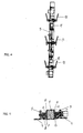
- Fig. 1
- eine Gesamtdarstellung einer Türanordnung in geöffneter Position;
- Fig. 2
- eine Darstellung wie
Fig. 1 in geschlossener Position mit einem zusätzlichen Stellzylinder zum Öffnen und Schließen; - Fig. 3
- eine Darstellung einer verstellbaren Verriegelungsleiste;
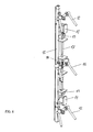
- Fig. 4
- eine Seitenansicht als Schnitt der Zarge mit den Stellelementen für die verstellbare Verriegelungsleiste;
- Fig. 5
- eine verkürzte Schnittdarstellung gemäß Linie V-V der
Fig. 2 mit den Verriegelungsleisten in einer Verriegelungsposition; - Fig. 6
- eine Perspektivdarstellung einer verstellbaren Verriegelungsleiste mit seinen Stellelementen und einer Seilzugstange;
- Fig. 7
- eine vergrößerte Darstellung eines Teilbereiches gemäß
Fig. 6 und - Fig. 8
- einen verstellbaren Betätigungshebel für eine verstellbare Verriegelungsleiste
- Fig. 1
- an overall view of a door assembly in the open position;
- Fig. 2
- a representation like
Fig. 1 in the closed position with an additional actuating cylinder for opening and closing; - Fig. 3
- an illustration of an adjustable locking bar;
- Fig. 4
- a side view as a section of the frame with the adjusting elements for the adjustable locking bar;
- Fig. 5
- a shortened sectional view according to line VV of
Fig. 2 with the locking strips in a locking position; - Fig. 6
- a perspective view of an adjustable locking bar with its adjusting elements and a cable pull rod;
- Fig. 7
- an enlarged view of a portion according to
Fig. 6 and - Fig. 8
- an adjustable operating lever for an adjustable locking strip
Bei der dargestellten Anordnung ist ein Flügel 1 als Türelement über Scharniere 2 schwenkbar zum Verschließen einer Öffnung 3 an einer mit einem Schott 4 ortsfest zugeordneten Zarge 5 verbunden. Für die Stellbewegung ist gemäß
Die Zarge 5 an der Scharnierseite mit der verbundenen Seite des Flügels 1 besitzt eine ortsfeste Verriegelungsleiste 6 zum Eingriff bzw. Einsetzen in eine korrespondierende Nut 7 eines Flügelrahmens 8, wobei das Profil des Flügelrahmens 8 eine Abschrägung zur Zuführung der Verriegelungsleiste 6 in die Nut 7 aufweist. Ein überdeckender Außenbereich des Flügelrahmens 8 besitzt eine Dichtung 9, die an der Zarge 5 in geschlossenem Zustand des Flügels 1 anliegt. Die ortsfeste Verriegelungsleiste 6 ist dabei justierbar in der Zarge 5 angeordnet.The
Die Zarge 5 an der gegenüberliegenden Seite besitzt dagegen eine in der Zarge 5 geführte und verstellbare Verriegelungsleiste 10, die über einen Pneumatikzylinder 11 und verschwenkbare angeordnete Betätigungshebel 12 in eine korrespondierende Nut 13 des Flügelrahmens 8 zur Verriegelung einsetzbar ist und in dieser Verriegelungsstellung gehalten wird. Die Pneumatikzylinder 11 und die Betätigungshebel 12 greifen dabei über Bolzen 14 an der Verriegelungsleiste 10 an, wobei die verschwenkten Betätigungshebel 12 über eine Übertotpunktlagerung in der Verriegelungsposition gehalten sind.The
Gemäß
Zusätzlich sind an den außenliegenden Flächen von Flügel 1 und Zarge 5 in der Schließposition gegeneinanderstoßende Aufsatzelemente 20 und 21 aufgebracht, die als Schockbegrenzer dienen.In addition, against the outer surfaces of the
Claims (7)
Priority Applications (1)
| Application Number | Priority Date | Filing Date | Title |
|---|---|---|---|
| PL13003957T PL2724929T3 (en) | 2012-10-23 | 2013-08-08 | Device for shock-proof door or porthole assembly on naval ships |
Applications Claiming Priority (1)
| Application Number | Priority Date | Filing Date | Title |
|---|---|---|---|
| DE102012021583 | 2012-10-23 |
Publications (2)
| Publication Number | Publication Date |
|---|---|
| EP2724929A1 true EP2724929A1 (en) | 2014-04-30 |
| EP2724929B1 EP2724929B1 (en) | 2017-11-08 |
Family
ID=48998389
Family Applications (1)
| Application Number | Title | Priority Date | Filing Date |
|---|---|---|---|
| EP13003957.1A Active EP2724929B1 (en) | 2012-10-23 | 2013-08-08 | Device for shock-proof door or porthole assembly on naval ships |
Country Status (10)
| Country | Link |
|---|---|
| US (1) | US8984812B2 (en) |
| EP (1) | EP2724929B1 (en) |
| KR (1) | KR101832009B1 (en) |
| AU (1) | AU2013245574B2 (en) |
| BR (1) | BR102013026598B1 (en) |
| CA (1) | CA2830060C (en) |
| DE (1) | DE102013016963A1 (en) |
| ES (1) | ES2657045T3 (en) |
| NO (1) | NO2838843T3 (en) |
| PL (1) | PL2724929T3 (en) |
Families Citing this family (10)
| Publication number | Priority date | Publication date | Assignee | Title |
|---|---|---|---|---|
| US9726288B2 (en) * | 2014-04-29 | 2017-08-08 | Eminent Technologies, Llc | Pressure vessel closure |
| CN108222788A (en) * | 2018-02-06 | 2018-06-29 | 张阳鑫 | A kind of linkage lock anti-reflective bullet closed guard gate using Fluid pressure |
| RU188854U1 (en) * | 2019-02-27 | 2019-04-25 | Общество с ограниченной ответственностью "ВС-ГРУПП" | AUDIT HATCH |
| RU2717401C1 (en) * | 2019-05-13 | 2020-03-23 | Общество с ограниченной ответственностью "Феррумленд" | Outer loop fast-action water-and-gas steel |
| US11414907B2 (en) * | 2019-07-01 | 2022-08-16 | Gulfstream Aerospace Corporation | Door assembly and method for making the same, and aircraft including a door assembly |
| CN111852240A (en) * | 2020-07-13 | 2020-10-30 | 临沂矿业集团有限责任公司 | Automatic opening and closing device for airtight door |
| USD991134S1 (en) * | 2020-07-23 | 2023-07-04 | Peter J. Luciani, JR. | Deck hatch |
| CN112796636B (en) * | 2021-01-13 | 2022-08-09 | 铜陵市金鑫人防工程防护设备有限公司 | Tunnel positive line protective airtight door for civil air defense engineering |
| US11732528B2 (en) * | 2021-06-29 | 2023-08-22 | Toshiba International Corporation | Door fastener retaining assembly, system, and method |
| CN114809824B (en) * | 2022-05-06 | 2023-10-03 | 北京奔驰汽车有限公司 | Method and device for opening and closing heavy door, computer equipment and storage medium |
Citations (5)
| Publication number | Priority date | Publication date | Assignee | Title |
|---|---|---|---|---|
| US1395777A (en) * | 1921-05-26 | 1921-11-01 | Stuart Orsini | Bulkhead-door |
| US6123370A (en) * | 1999-03-31 | 2000-09-26 | Hartwell Corporation | Increased strength dogging mechanism |
| US6640498B1 (en) * | 1999-01-04 | 2003-11-04 | Nederlandse Organisatie Voor Toegepast-Natuurwetenschappelijk Onderzoek Tno | Door structure with deformable peripheral edge |
| US20070022662A1 (en) * | 2005-08-01 | 2007-02-01 | Rising Benjamin E | Watertight Door |
| DE102006041192B3 (en) * | 2006-08-28 | 2008-03-27 | Blohm + Voss Gmbh | Shock or gas/waterproof door or hatch arranging device for naval ship, has support units and areas between support units arranged in corner areas over ball body for forming circulating closed operating ring |
Family Cites Families (18)
| Publication number | Priority date | Publication date | Assignee | Title |
|---|---|---|---|---|
| US121701A (en) * | 1871-12-12 | Improvement in sash-supporters | ||
| US2271952A (en) * | 1941-11-06 | 1942-02-03 | Joseph F Raus | Quick-acting, watertight ship door |
| US2739343A (en) * | 1951-07-03 | 1956-03-27 | Ole O Rahm | Hatch cover and self-adjusting hinge therefor |
| GB774536A (en) * | 1954-04-30 | 1957-05-08 | English Electric Co Ltd | Improvements in and relating to doors |
| US2766860A (en) * | 1955-12-07 | 1956-10-16 | John P Travis | Pivoted window and retractible sealing means therefor |
| GB1291854A (en) * | 1969-02-07 | 1972-10-04 | British Aircraft Corp Ltd | Aircraft doors |
| DE2343066A1 (en) * | 1972-09-01 | 1974-03-07 | Waertsilae Oy Ab | DOOR ARRANGEMENT |
| US5086587A (en) * | 1991-01-30 | 1992-02-11 | Andrews Zenas B | Balanced beam latching apparatus |
| FI110155B (en) * | 1994-12-27 | 2002-11-29 | Euroshield Oy | Magnetically protected room door structure |
| DE29506177U1 (en) | 1995-04-18 | 1995-06-01 | Rekord Fenster & Tueren Gmbh & | Hinge-side door security |
| US7213530B2 (en) * | 2002-02-04 | 2007-05-08 | Kazak Composites, Incorporated | Hatch or door system for securing and sealing openings in marine vessels |
| US6675536B1 (en) * | 2002-07-31 | 2004-01-13 | Williams-Pyro, Inc. | Door frame closing and securing apparatus |
| US6799396B1 (en) * | 2002-12-19 | 2004-10-05 | The United States Of America As Represented By The Secretary Of The Navy | Watertight door closure |
| DE202005018625U1 (en) | 2005-11-28 | 2007-04-12 | Sylid Systemlogistik & Industriedienstleistung Gmbh | Locking device for a door leaf/window casement element suspended in a door/window frame so as to rotate has a ledger to work together with a contact strip |
| US8091282B2 (en) * | 2005-12-30 | 2012-01-10 | Secura-Seal Technologies Llc | Combined sealing system and seal activation system for door/window |
| KR100794281B1 (en) * | 2006-12-20 | 2008-01-17 | (주)삼부에이티씨 | The door of ship |
| US20080295410A1 (en) * | 2007-06-01 | 2008-12-04 | Speyer Door And Window, Inc. | Acoustic/thermal break and framing system for door/window |
| SI2273055T1 (en) * | 2009-05-04 | 2016-05-31 | Air-Lux Technik Ag | Device for sealingly closing a room opening |
-
2013
- 2013-03-15 NO NO13778574A patent/NO2838843T3/no unknown
- 2013-08-08 PL PL13003957T patent/PL2724929T3/en unknown
- 2013-08-08 ES ES13003957.1T patent/ES2657045T3/en active Active
- 2013-08-08 EP EP13003957.1A patent/EP2724929B1/en active Active
- 2013-08-23 KR KR1020130100033A patent/KR101832009B1/en active IP Right Grant
- 2013-10-09 DE DE102013016963.1A patent/DE102013016963A1/en not_active Withdrawn
- 2013-10-15 BR BR102013026598-5A patent/BR102013026598B1/en active IP Right Grant
- 2013-10-16 US US14/055,005 patent/US8984812B2/en active Active
- 2013-10-16 CA CA2830060A patent/CA2830060C/en active Active
- 2013-10-21 AU AU2013245574A patent/AU2013245574B2/en active Active
Patent Citations (5)
| Publication number | Priority date | Publication date | Assignee | Title |
|---|---|---|---|---|
| US1395777A (en) * | 1921-05-26 | 1921-11-01 | Stuart Orsini | Bulkhead-door |
| US6640498B1 (en) * | 1999-01-04 | 2003-11-04 | Nederlandse Organisatie Voor Toegepast-Natuurwetenschappelijk Onderzoek Tno | Door structure with deformable peripheral edge |
| US6123370A (en) * | 1999-03-31 | 2000-09-26 | Hartwell Corporation | Increased strength dogging mechanism |
| US20070022662A1 (en) * | 2005-08-01 | 2007-02-01 | Rising Benjamin E | Watertight Door |
| DE102006041192B3 (en) * | 2006-08-28 | 2008-03-27 | Blohm + Voss Gmbh | Shock or gas/waterproof door or hatch arranging device for naval ship, has support units and areas between support units arranged in corner areas over ball body for forming circulating closed operating ring |
Also Published As
| Publication number | Publication date |
|---|---|
| AU2013245574B2 (en) | 2017-05-18 |
| CA2830060A1 (en) | 2014-04-23 |
| NO2838843T3 (en) | 2018-03-03 |
| BR102013026598B1 (en) | 2021-10-26 |
| BR102013026598A2 (en) | 2014-12-09 |
| DE102013016963A1 (en) | 2014-04-24 |
| AU2013245574A1 (en) | 2014-05-08 |
| CA2830060C (en) | 2019-07-09 |
| KR20140051769A (en) | 2014-05-02 |
| BR102013026598A8 (en) | 2021-08-17 |
| KR101832009B1 (en) | 2018-02-23 |
| US20140109480A1 (en) | 2014-04-24 |
| PL2724929T3 (en) | 2018-04-30 |
| US8984812B2 (en) | 2015-03-24 |
| ES2657045T3 (en) | 2018-03-01 |
| EP2724929B1 (en) | 2017-11-08 |
Similar Documents
| Publication | Publication Date | Title |
|---|---|---|
| EP2724929B1 (en) | Device for shock-proof door or porthole assembly on naval ships | |
| EP1959080B1 (en) | Fitting for a sliding leaf of a door or window | |
| DE102007053554A1 (en) | Lock for a cargo gate in an airplane | |
| DE102018121307B4 (en) | Airplane door lock, airplane door and airplane with an airplane door | |
| DE102010013715B4 (en) | An aircraft door latch mechanism, method of locking an aircraft door and aircraft door | |
| DE102015000197A1 (en) | Security door leaf | |
| DE102006041192B3 (en) | Shock or gas/waterproof door or hatch arranging device for naval ship, has support units and areas between support units arranged in corner areas over ball body for forming circulating closed operating ring | |
| EP2540616B1 (en) | Closing mechanism for a sliding door that closes with power assistance | |
| DE102017005781A1 (en) | Hinge for a door or a window and door or window equipped with it | |
| EP2369115A2 (en) | Lift protection for sliding windows or sliding doors | |
| DE102013218948A1 (en) | Sliding window or sliding door arrangement | |
| DE102011077631B4 (en) | Automatic sliding door system | |
| DE2455479C2 (en) | Lock for locking sliding windows or doors | |
| EP3798390B1 (en) | Folding installation | |
| EP3246500B1 (en) | Sliding door system comprising damper assembly | |
| DE102008063769A1 (en) | Swing hatch, especially for military vehicles | |
| DE595545C (en) | Horizontally displaceable window is suspended on a running rail above the window by means of rollers | |
| EP3425149A1 (en) | Lifting/sliding structure, in particular lifting/sliding door or window | |
| DE102021115490B4 (en) | Locking device for doors hinged on both sides | |
| EP2876240B1 (en) | Window or door | |
| AT520893B1 (en) | Door for vehicle superstructures | |
| DE102018129520B4 (en) | Shutters, facade arrangement and procedures therefor | |
| DE102009004811A1 (en) | Device for locking passenger door against body structure of aircraft, has threaded pins cooperating with threaded bushes of edge frames such that movement of frame releases form-fit locking or opening of door over breadth of door joint | |
| DE562576C (en) | Espagnolette closure | |
| EP1961900B1 (en) | Device for shock-proof door assembly |
Legal Events
| Date | Code | Title | Description |
|---|---|---|---|
| PUAI | Public reference made under article 153(3) epc to a published international application that has entered the european phase |
Free format text: ORIGINAL CODE: 0009012 |
|
| 17P | Request for examination filed |
Effective date: 20130808 |
|
| AK | Designated contracting states |
Kind code of ref document: A1 Designated state(s): AL AT BE BG CH CY CZ DE DK EE ES FI FR GB GR HR HU IE IS IT LI LT LU LV MC MK MT NL NO PL PT RO RS SE SI SK SM TR |
|
| AX | Request for extension of the european patent |
Extension state: BA ME |
|
| GRAP | Despatch of communication of intention to grant a patent |
Free format text: ORIGINAL CODE: EPIDOSNIGR1 |
|
| STAA | Information on the status of an ep patent application or granted ep patent |
Free format text: STATUS: GRANT OF PATENT IS INTENDED |
|
| RIC1 | Information provided on ipc code assigned before grant |
Ipc: B63B 43/32 20060101AFI20170515BHEP Ipc: B63B 19/00 20060101ALI20170515BHEP |
|
| INTG | Intention to grant announced |
Effective date: 20170609 |
|
| GRAS | Grant fee paid |
Free format text: ORIGINAL CODE: EPIDOSNIGR3 |
|
| GRAA | (expected) grant |
Free format text: ORIGINAL CODE: 0009210 |
|
| STAA | Information on the status of an ep patent application or granted ep patent |
Free format text: STATUS: THE PATENT HAS BEEN GRANTED |
|
| AK | Designated contracting states |
Kind code of ref document: B1 Designated state(s): AL AT BE BG CH CY CZ DE DK EE ES FI FR GB GR HR HU IE IS IT LI LT LU LV MC MK MT NL NO PL PT RO RS SE SI SK SM TR |
|
| REG | Reference to a national code |
Ref country code: GB Ref legal event code: FG4D Free format text: NOT ENGLISH |
|
| REG | Reference to a national code |
Ref country code: AT Ref legal event code: REF Ref document number: 943865 Country of ref document: AT Kind code of ref document: T Effective date: 20171115 Ref country code: CH Ref legal event code: EP |
|
| REG | Reference to a national code |
Ref country code: IE Ref legal event code: FG4D Free format text: LANGUAGE OF EP DOCUMENT: GERMAN |
|
| REG | Reference to a national code |
Ref country code: DE Ref legal event code: R096 Ref document number: 502013008746 Country of ref document: DE |
|
| REG | Reference to a national code |
Ref country code: DE Ref legal event code: R084 Ref document number: 502013008746 Country of ref document: DE |
|
| REG | Reference to a national code |
Ref country code: NL Ref legal event code: FP |
|
| REG | Reference to a national code |
Ref country code: SE Ref legal event code: TRGR |
|
| REG | Reference to a national code |
Ref country code: ES Ref legal event code: FG2A Ref document number: 2657045 Country of ref document: ES Kind code of ref document: T3 Effective date: 20180301 |
|
| REG | Reference to a national code |
Ref country code: LT Ref legal event code: MG4D |
|
| REG | Reference to a national code |
Ref country code: NO Ref legal event code: T2 Effective date: 20171108 |
|
| PG25 | Lapsed in a contracting state [announced via postgrant information from national office to epo] |
Ref country code: FI Free format text: LAPSE BECAUSE OF FAILURE TO SUBMIT A TRANSLATION OF THE DESCRIPTION OR TO PAY THE FEE WITHIN THE PRESCRIBED TIME-LIMIT Effective date: 20171108 Ref country code: LT Free format text: LAPSE BECAUSE OF FAILURE TO SUBMIT A TRANSLATION OF THE DESCRIPTION OR TO PAY THE FEE WITHIN THE PRESCRIBED TIME-LIMIT Effective date: 20171108 |
|
| PG25 | Lapsed in a contracting state [announced via postgrant information from national office to epo] |
Ref country code: RS Free format text: LAPSE BECAUSE OF FAILURE TO SUBMIT A TRANSLATION OF THE DESCRIPTION OR TO PAY THE FEE WITHIN THE PRESCRIBED TIME-LIMIT Effective date: 20171108 Ref country code: GR Free format text: LAPSE BECAUSE OF FAILURE TO SUBMIT A TRANSLATION OF THE DESCRIPTION OR TO PAY THE FEE WITHIN THE PRESCRIBED TIME-LIMIT Effective date: 20180209 Ref country code: IS Free format text: LAPSE BECAUSE OF FAILURE TO SUBMIT A TRANSLATION OF THE DESCRIPTION OR TO PAY THE FEE WITHIN THE PRESCRIBED TIME-LIMIT Effective date: 20180308 Ref country code: BG Free format text: LAPSE BECAUSE OF FAILURE TO SUBMIT A TRANSLATION OF THE DESCRIPTION OR TO PAY THE FEE WITHIN THE PRESCRIBED TIME-LIMIT Effective date: 20180208 Ref country code: HR Free format text: LAPSE BECAUSE OF FAILURE TO SUBMIT A TRANSLATION OF THE DESCRIPTION OR TO PAY THE FEE WITHIN THE PRESCRIBED TIME-LIMIT Effective date: 20171108 Ref country code: LV Free format text: LAPSE BECAUSE OF FAILURE TO SUBMIT A TRANSLATION OF THE DESCRIPTION OR TO PAY THE FEE WITHIN THE PRESCRIBED TIME-LIMIT Effective date: 20171108 |
|
| PG25 | Lapsed in a contracting state [announced via postgrant information from national office to epo] |
Ref country code: SK Free format text: LAPSE BECAUSE OF FAILURE TO SUBMIT A TRANSLATION OF THE DESCRIPTION OR TO PAY THE FEE WITHIN THE PRESCRIBED TIME-LIMIT Effective date: 20171108 Ref country code: CY Free format text: LAPSE BECAUSE OF FAILURE TO SUBMIT A TRANSLATION OF THE DESCRIPTION OR TO PAY THE FEE WITHIN THE PRESCRIBED TIME-LIMIT Effective date: 20171108 Ref country code: EE Free format text: LAPSE BECAUSE OF FAILURE TO SUBMIT A TRANSLATION OF THE DESCRIPTION OR TO PAY THE FEE WITHIN THE PRESCRIBED TIME-LIMIT Effective date: 20171108 Ref country code: DK Free format text: LAPSE BECAUSE OF FAILURE TO SUBMIT A TRANSLATION OF THE DESCRIPTION OR TO PAY THE FEE WITHIN THE PRESCRIBED TIME-LIMIT Effective date: 20171108 Ref country code: CZ Free format text: LAPSE BECAUSE OF FAILURE TO SUBMIT A TRANSLATION OF THE DESCRIPTION OR TO PAY THE FEE WITHIN THE PRESCRIBED TIME-LIMIT Effective date: 20171108 |
|
| REG | Reference to a national code |
Ref country code: DE Ref legal event code: R097 Ref document number: 502013008746 Country of ref document: DE |
|
| REG | Reference to a national code |
Ref country code: FR Ref legal event code: PLFP Year of fee payment: 6 |
|
| PG25 | Lapsed in a contracting state [announced via postgrant information from national office to epo] |
Ref country code: SM Free format text: LAPSE BECAUSE OF FAILURE TO SUBMIT A TRANSLATION OF THE DESCRIPTION OR TO PAY THE FEE WITHIN THE PRESCRIBED TIME-LIMIT Effective date: 20171108 Ref country code: RO Free format text: LAPSE BECAUSE OF FAILURE TO SUBMIT A TRANSLATION OF THE DESCRIPTION OR TO PAY THE FEE WITHIN THE PRESCRIBED TIME-LIMIT Effective date: 20171108 |
|
| PLBE | No opposition filed within time limit |
Free format text: ORIGINAL CODE: 0009261 |
|
| STAA | Information on the status of an ep patent application or granted ep patent |
Free format text: STATUS: NO OPPOSITION FILED WITHIN TIME LIMIT |
|
| PG25 | Lapsed in a contracting state [announced via postgrant information from national office to epo] |
Ref country code: MT Free format text: LAPSE BECAUSE OF FAILURE TO SUBMIT A TRANSLATION OF THE DESCRIPTION OR TO PAY THE FEE WITHIN THE PRESCRIBED TIME-LIMIT Effective date: 20171108 |
|
| 26N | No opposition filed |
Effective date: 20180809 |
|
| PG25 | Lapsed in a contracting state [announced via postgrant information from national office to epo] |
Ref country code: SI Free format text: LAPSE BECAUSE OF FAILURE TO SUBMIT A TRANSLATION OF THE DESCRIPTION OR TO PAY THE FEE WITHIN THE PRESCRIBED TIME-LIMIT Effective date: 20171108 |
|
| PG25 | Lapsed in a contracting state [announced via postgrant information from national office to epo] |
Ref country code: MC Free format text: LAPSE BECAUSE OF FAILURE TO SUBMIT A TRANSLATION OF THE DESCRIPTION OR TO PAY THE FEE WITHIN THE PRESCRIBED TIME-LIMIT Effective date: 20171108 |
|
| REG | Reference to a national code |
Ref country code: CH Ref legal event code: PL |
|
| PG25 | Lapsed in a contracting state [announced via postgrant information from national office to epo] |
Ref country code: LI Free format text: LAPSE BECAUSE OF NON-PAYMENT OF DUE FEES Effective date: 20180831 Ref country code: LU Free format text: LAPSE BECAUSE OF NON-PAYMENT OF DUE FEES Effective date: 20180808 Ref country code: CH Free format text: LAPSE BECAUSE OF NON-PAYMENT OF DUE FEES Effective date: 20180831 |
|
| REG | Reference to a national code |
Ref country code: BE Ref legal event code: MM Effective date: 20180831 |
|
| REG | Reference to a national code |
Ref country code: IE Ref legal event code: MM4A |
|
| PG25 | Lapsed in a contracting state [announced via postgrant information from national office to epo] |
Ref country code: IE Free format text: LAPSE BECAUSE OF NON-PAYMENT OF DUE FEES Effective date: 20180808 |
|
| PG25 | Lapsed in a contracting state [announced via postgrant information from national office to epo] |
Ref country code: BE Free format text: LAPSE BECAUSE OF NON-PAYMENT OF DUE FEES Effective date: 20180831 |
|
| REG | Reference to a national code |
Ref country code: DE Ref legal event code: R081 Ref document number: 502013008746 Country of ref document: DE Owner name: THYSSENKRUPP MARINE SYSTEMS GMBH, DE Free format text: FORMER OWNER: THYSSENKRUPP MARINE SYSTEMS GMBH, 24143 KIEL, DE |
|
| REG | Reference to a national code |
Ref country code: AT Ref legal event code: MM01 Ref document number: 943865 Country of ref document: AT Kind code of ref document: T Effective date: 20180808 |
|
| PG25 | Lapsed in a contracting state [announced via postgrant information from national office to epo] |
Ref country code: AT Free format text: LAPSE BECAUSE OF NON-PAYMENT OF DUE FEES Effective date: 20180808 |
|
| PG25 | Lapsed in a contracting state [announced via postgrant information from national office to epo] |
Ref country code: TR Free format text: LAPSE BECAUSE OF FAILURE TO SUBMIT A TRANSLATION OF THE DESCRIPTION OR TO PAY THE FEE WITHIN THE PRESCRIBED TIME-LIMIT Effective date: 20171108 |
|
| PG25 | Lapsed in a contracting state [announced via postgrant information from national office to epo] |
Ref country code: HU Free format text: LAPSE BECAUSE OF FAILURE TO SUBMIT A TRANSLATION OF THE DESCRIPTION OR TO PAY THE FEE WITHIN THE PRESCRIBED TIME-LIMIT; INVALID AB INITIO Effective date: 20130808 Ref country code: PT Free format text: LAPSE BECAUSE OF FAILURE TO SUBMIT A TRANSLATION OF THE DESCRIPTION OR TO PAY THE FEE WITHIN THE PRESCRIBED TIME-LIMIT Effective date: 20171108 |
|
| PG25 | Lapsed in a contracting state [announced via postgrant information from national office to epo] |
Ref country code: MK Free format text: LAPSE BECAUSE OF NON-PAYMENT OF DUE FEES Effective date: 20171108 |
|
| PG25 | Lapsed in a contracting state [announced via postgrant information from national office to epo] |
Ref country code: AL Free format text: LAPSE BECAUSE OF FAILURE TO SUBMIT A TRANSLATION OF THE DESCRIPTION OR TO PAY THE FEE WITHIN THE PRESCRIBED TIME-LIMIT Effective date: 20171108 |
|
| P01 | Opt-out of the competence of the unified patent court (upc) registered |
Effective date: 20230530 |
|
| PGFP | Annual fee paid to national office [announced via postgrant information from national office to epo] |
Ref country code: NL Payment date: 20230821 Year of fee payment: 11 |
|
| PGFP | Annual fee paid to national office [announced via postgrant information from national office to epo] |
Ref country code: NO Payment date: 20230824 Year of fee payment: 11 Ref country code: IT Payment date: 20230825 Year of fee payment: 11 Ref country code: GB Payment date: 20230822 Year of fee payment: 11 |
|
| PGFP | Annual fee paid to national office [announced via postgrant information from national office to epo] |
Ref country code: SE Payment date: 20230821 Year of fee payment: 11 Ref country code: PL Payment date: 20230727 Year of fee payment: 11 Ref country code: FR Payment date: 20230824 Year of fee payment: 11 Ref country code: DE Payment date: 20230821 Year of fee payment: 11 |
|
| PGFP | Annual fee paid to national office [announced via postgrant information from national office to epo] |
Ref country code: ES Payment date: 20231027 Year of fee payment: 11 |