EP2724040B1 - Sicherheitskupplung - Google Patents
Sicherheitskupplung Download PDFInfo
- Publication number
- EP2724040B1 EP2724040B1 EP12751628.4A EP12751628A EP2724040B1 EP 2724040 B1 EP2724040 B1 EP 2724040B1 EP 12751628 A EP12751628 A EP 12751628A EP 2724040 B1 EP2724040 B1 EP 2724040B1
- Authority
- EP
- European Patent Office
- Prior art keywords
- safety
- coupling
- notches
- coupling member
- inactive
- Prior art date
- Legal status (The legal status is an assumption and is not a legal conclusion. Google has not performed a legal analysis and makes no representation as to the accuracy of the status listed.)
- Active
Links
Images


Classifications
-
- F—MECHANICAL ENGINEERING; LIGHTING; HEATING; WEAPONS; BLASTING
- F16—ENGINEERING ELEMENTS AND UNITS; GENERAL MEASURES FOR PRODUCING AND MAINTAINING EFFECTIVE FUNCTIONING OF MACHINES OR INSTALLATIONS; THERMAL INSULATION IN GENERAL
- F16D—COUPLINGS FOR TRANSMITTING ROTATION; CLUTCHES; BRAKES
- F16D13/00—Friction clutches
- F16D13/12—Friction clutches with an expansible band or coil co-operating with the inner surface of a drum or the like
-
- F—MECHANICAL ENGINEERING; LIGHTING; HEATING; WEAPONS; BLASTING
- F16—ENGINEERING ELEMENTS AND UNITS; GENERAL MEASURES FOR PRODUCING AND MAINTAINING EFFECTIVE FUNCTIONING OF MACHINES OR INSTALLATIONS; THERMAL INSULATION IN GENERAL
- F16D—COUPLINGS FOR TRANSMITTING ROTATION; CLUTCHES; BRAKES
- F16D1/00—Couplings for rigidly connecting two coaxial shafts or other movable machine elements
- F16D1/06—Couplings for rigidly connecting two coaxial shafts or other movable machine elements for attachment of a member on a shaft or on a shaft-end
- F16D1/08—Couplings for rigidly connecting two coaxial shafts or other movable machine elements for attachment of a member on a shaft or on a shaft-end with clamping hub; with hub and longitudinal key
- F16D1/0805—Couplings for rigidly connecting two coaxial shafts or other movable machine elements for attachment of a member on a shaft or on a shaft-end with clamping hub; with hub and longitudinal key with radial clamping due to deformation of a resilient body or a body of fluid
-
- F—MECHANICAL ENGINEERING; LIGHTING; HEATING; WEAPONS; BLASTING
- F16—ENGINEERING ELEMENTS AND UNITS; GENERAL MEASURES FOR PRODUCING AND MAINTAINING EFFECTIVE FUNCTIONING OF MACHINES OR INSTALLATIONS; THERMAL INSULATION IN GENERAL
- F16D—COUPLINGS FOR TRANSMITTING ROTATION; CLUTCHES; BRAKES
- F16D3/00—Yielding couplings, i.e. with means permitting movement between the connected parts during the drive
- F16D3/02—Yielding couplings, i.e. with means permitting movement between the connected parts during the drive adapted to specific functions
-
- F—MECHANICAL ENGINEERING; LIGHTING; HEATING; WEAPONS; BLASTING
- F16—ENGINEERING ELEMENTS AND UNITS; GENERAL MEASURES FOR PRODUCING AND MAINTAINING EFFECTIVE FUNCTIONING OF MACHINES OR INSTALLATIONS; THERMAL INSULATION IN GENERAL
- F16D—COUPLINGS FOR TRANSMITTING ROTATION; CLUTCHES; BRAKES
- F16D43/00—Automatic clutches
- F16D43/28—Automatic clutches actuated by fluid pressure
-
- F—MECHANICAL ENGINEERING; LIGHTING; HEATING; WEAPONS; BLASTING
- F16—ENGINEERING ELEMENTS AND UNITS; GENERAL MEASURES FOR PRODUCING AND MAINTAINING EFFECTIVE FUNCTIONING OF MACHINES OR INSTALLATIONS; THERMAL INSULATION IN GENERAL
- F16D—COUPLINGS FOR TRANSMITTING ROTATION; CLUTCHES; BRAKES
- F16D7/00—Slip couplings, e.g. slipping on overload, for absorbing shock
- F16D7/02—Slip couplings, e.g. slipping on overload, for absorbing shock of the friction type
- F16D7/021—Slip couplings, e.g. slipping on overload, for absorbing shock of the friction type with radially applied torque-limiting friction surfaces
-
- F—MECHANICAL ENGINEERING; LIGHTING; HEATING; WEAPONS; BLASTING
- F16—ENGINEERING ELEMENTS AND UNITS; GENERAL MEASURES FOR PRODUCING AND MAINTAINING EFFECTIVE FUNCTIONING OF MACHINES OR INSTALLATIONS; THERMAL INSULATION IN GENERAL
- F16D—COUPLINGS FOR TRANSMITTING ROTATION; CLUTCHES; BRAKES
- F16D9/00—Couplings with safety member for disconnecting, e.g. breaking or melting member
- F16D9/06—Couplings with safety member for disconnecting, e.g. breaking or melting member by breaking due to shear stress
-
- F—MECHANICAL ENGINEERING; LIGHTING; HEATING; WEAPONS; BLASTING
- F16—ENGINEERING ELEMENTS AND UNITS; GENERAL MEASURES FOR PRODUCING AND MAINTAINING EFFECTIVE FUNCTIONING OF MACHINES OR INSTALLATIONS; THERMAL INSULATION IN GENERAL
- F16D—COUPLINGS FOR TRANSMITTING ROTATION; CLUTCHES; BRAKES
- F16D9/00—Couplings with safety member for disconnecting, e.g. breaking or melting member
- F16D9/06—Couplings with safety member for disconnecting, e.g. breaking or melting member by breaking due to shear stress
- F16D9/10—Couplings with safety member for disconnecting, e.g. breaking or melting member by breaking due to shear stress having a part movable after disconnection so as to provide reconnection, e.g. advanceable shear pins
Definitions
- the present invention relates generally to a safety coupling.
- safety coupling means a coordination between;
- a safety arrangement with an overload protector is adapted to take the coupling unit from an "active" position ("on” mode) to an “inactive” position ("off” mode) as soon as the transmitted torque exceeds a predetermined value and wherein the torque-transmitting coupling unit is adapted, via the influence of a means and/or the safety arrangement, to make the coupling or coupling unit, upon transmission of torque, immediately switch over from an "active" position to an "inactive” position.
- the safety arrangement can assume an "active” position in order to retain the coupling unit in an “active” position, as long as the torque is below a predetermined maximized value, while the safety arrangement assumes an "inactive” or inactivating position in order to bring the coupling to an "inactive” position as soon as torque exceeds a predetermined maximized value.
- the friction coupling or friction coupling unit will, once the predetermined value has been exceeded, create a relative movement between a first, driving coupling member and a second, driven coupling member and a friction surface located between the two.
- Such a friction surface can then be formed as one or more opposing, coaxially arranged cylinder surfaces, one or more coaxially related flat or tapered circular or conical friction surfaces and the like.
- the invention will, as follows and as a proposed embodiment, be illustrated as a safety coupling with cylindrical friction surfaces, related to the torque-transmitting coupling unit.
- the invention aims primarily to obtaining an application for a safety coupling, with a related "on"/"off” coupling unit toward and into an initial “active” (retaining) position or toward and into a final “inactive” (releasing) position, and with a safety arrangement coordinated with a safety mechanism that can be actuated and adjusted to various positions.
- Safety couplings of the relevant type are thus adapted to, via rotary motion, allow for the transmission of torque, such as time-varying torque, between a first, driving coupling member and a second, driven coupling member forming part of the selected friction coupling or friction coupling unit.
- the present invention requires for its operation, according to an aspect of the present invention, that the afore-mentioned actuatable safety mechanism be adapted such that when a preselected torque and a maximized relative movement caused by this high torque between the first and the second coupling members are exceeded, the safety mechanism is actuated in a relative displacement from an initial "active" position toward and into an "inactive” position for the coupling unit's coupling members.
- Said safety arrangement must thus be adapted to permit a limited yet maximized relative movement between the first and the second coupling members within the friction coupling, this limited relative movement being adapted to correspond to a selected arc angle and/or a selected arcuate distance, between its initial "active" position and its final “inactive” position, where the safety arrangement is adapted to instantaneously allow the coupling unit actuate to its "inactive" position and thereby instantaneously allow the transmission of excessive torque via the coupling unit, by momentarily exposing the friction surfaces forming part of and opposing the coupling.
- the present invention relates to an application for large rock drills, intended to allow for the drilling of holes in rock, such as for vehicular and/or rail traffic and/or tunnels and/or for other purposes, and where such drills are allocated a number of coordinated drill stations, distributed along the circumference of a circular cutter head.
- These drills with their circumferential drill stations are designed to drill into rock during successive operating cycles, each cycle being associated with a beginning and an end, with a first operating cycle being terminated and later replaced by a second subsequent operating cycle, and so on.
- the present invention intends to, via the safety arrangement and its interaction with the coupling unit and the safety mechanism, rapidly trigger the coupling unit to assume an "inactive" position at a high and relatively sustained torque, creating a maximized relative movement between the coupling members, but intends to accept high yet extremely short, so-called torque peaks occurring during a single operating cycle, without therefore allowing for the activation of the coupling unit trigger to its "inactive mode".
- one safety arrangement may be mentioned, being related to or integrally formed with a safety coupling, and coordinating with a safety mechanism, as disclosed in DE 40 28 158 .
- the safety coupling is actuatable by an adapted safety arrangement toward and into an initial active (retaining) position, or toward and into an inactive (releasing) position, with a connection to the above-described "on"/"off" function.
- These torque transmission coupling units are adapted to, via rotary motion, allow for the transmission of (high) torque between a first, driving coupling member and a second, driven coupling member.
- Said safety arrangement is adapted to, when a preselected torque and a relative motion caused by this high torque between the first and second coupling members are exceeded, be actuated, via a safety mechanism, in a displacement from its initial active position to its final inactive position, said safety arrangement being adapted to permit a limited relative movement between the first and the second coupling members corresponding to a selected maximized arcuate distance between its initial active position and its final inactive position, the safety arrangement being adapted to mechanically permit the coupling unit to be actuated to its inactive position by momentarily evacuating a cavity, filled with a medium under high pressure, of its contents (aqueous emulsion, oil).
- the known safety coupling with its allocated safety mechanism, is constructed such that a limited relative movement between the coupling members, caused primarily by short-term torque peaks exceeding a predetermined maximized torque value, will be progressively utilized and added to each and every successive work cycle, until the chosen maximum arcuate distance is fully utilized and the final inactive position of the arrangement can be achieved with an extremely small final relative movement, less than the maximum arcuate distance, during one operating cycle.
- the known safety coupling offers no visual inspection of, or easily ascertainable way of determining, the relative movement achieved between the coupling members at the start of each operating cycle.
- the aim of the present invention is to provide an improved safety coupling which solves the above problems by resetting and utilizing the maximum arcuate distance for each operating cycle.
- a safety coupling with an associated safety mechanism and a related safety arrangement, related to and/or integrally formed with each other, comprising a coupling unit adapted to, upon rotary motion, allow for the transmission of torque between two coaxially oriented coupling members, one driving, inner coupling member and one driven, external coupling member, with a cylindrical and/or circular and/or cone-shaped friction surface oriented between the inner coupling member and the outer coupling member, wherein the inner coupling member, being integrated into the coupling member, comprises a cylindrical or conically oriented cavity integrated into the coupling member and facing towards the frictional surface, which upon pressure applied by a medium (an aqueous emulsion or a oil pressure) is adapted to expand in the direction of the friction surface, wherein the safety coupling has the associated safety arrangement which is actuatable toward and into an initial actively retaining position, wherein the cavity is in an expanded position, or toward and into an inactive releasing position, wherein said cavity is in a non-expande
- the means allocated to the safety arrangement and/or the safety mechanism is adapted to, during a final operating cycle of the safety coupling, permit the safety mechanism to be restored/displaced in a direction toward and into the initial active position, in order to from this active position permit the provision of a limited relative movement between the first and the second coupling member in a subsequent operating cycle, and not successively permit the loading and reduction of the available arcuate distance with relative displacements between the coupling members arising from one or more preceding operating cycles.
- the initial position is chosen to fall within a maximized arc range where the safety mechanism can be displaced between the initially active position and the final inactive position and in opposite directions from an initial active starting position, depending on the chosen direction of rotation of the two coupling members.
- the limited relative movement between the first and second coupling members of the coupling is selected so as to always be below a few rotations, for example a single rotation, or a fraction of a rotation, for example a quarter rotation.
- relative movement caused between the coupling members beyond a selected, predetermined movement pattern brings the coupling members to an inactive position.
- the cavity interacts with a valve unit adapted to be opened instantaneously.
- valve assembly is adapted to be opened by means of a cutting operation, activated by the rotation of an adjacent disc.
- the means comprises a first disc or carrier disc which is formed along one side with one or more circumferential grooves or ridges, connecting to form a circle line, the length of the groove or arcuate distance between the ridges being adapted to correspond to the selected maximized arcuate distance between an active position and an inactive position of the coupling unit and wherein a stop means is adapted to engage with grooves or ridges to trigger the safety arrangement.
- the disc comprises along its second side, which is directed away from the first side, a number of inner notches facing the center, and a number of outer notches facing the periphery.
- the second side is allocated notches which are adapted to interact with one or more units, having projections, arranged to allow radial motion via a centrifugal device operating on centrifugal forces.
- the centrifugal device is adapted to, at a low rotation speed, engage with said inner notch, and at a high rotation speed, to engage with said outer notch.
- the disc's inner notches and outer notches are adapted to open towards an intermediate, substantially circular groove, and when said units and/or projections assume a radial position corresponding to the position of the intermediate groove, the safety arrangement returns to the initial active position of the coupling unit.
- the disc's inner and outer notches are tangentially displaced one half-step in relation to one another, in order to ensure that there is no rotation speed when the safety mechanism is not triggered in the event that the projection assumes a radial position corresponding to the position of the intermediate groove.
- the centrifugal device features units movable by rotary motion in a radial manner from one another, with allocated projections and is guided in its movement by radial grooves engageable with radial tracks on a disc or hub plate.
- the devices of the first and second spring units are pressed into their inner starting positions at a low or at no rotary motion.
- the projections on the movably arranged units are engageable only with the carrier plate in order to engage said stop means, which is adapted through forced rotation to open said valve assembly and to bring the coupling members to an inactive releasing position.
- Fig. 1 shows a format, linked and integrated as a single unit 2 to a safety coupling 1 with a safety arrangement 3b and/or a safety arrangement 3 related to and/or integrally formed with the guided and guiding safety arrangement 3b, wherein the safety coupling 1, with the associated safety mechanism 3a, which is actuatable toward and into an initial “active” (retaining) position or toward and into an “inactive” (releasing) position of coupling unit 3, is adapted to, upon rotary motion, allow the transmission of torque between a first, driving coupling member 10 and a second, driven coupling member 20 and wherein said actuatable safety arrangement 3b and/or safety mechanism 3a is adapted to, when a preselected high torque and a maximized relative movement caused by this high torque between the first 10 and second 20 coupling member are exceeded, be actuated in a displacement from an initial active position and intermediate position to a final inactive position of the coupling unit 3 and the coupling members 10, 20.
- Said guided safety arrangement 3b is thus adapted to allow a limited relative movement and distance of travel within a maximized arcuate distance between the first 10 and the second 20 coupling member to a selected arcuate distance between its initial active position and its final inactive position, where the safety mechanism 3a is 10 adapted to, after traveling such a distance, allow the coupling unit 3 and its coupling members 10, 20 to actuate to their inactive and releasing position.
- Fig.1 illustrates a known system "A", in which a motor unit 4 is adapted to allow the guided "on"-"off" safety arrangement 3b to be driven over a driving shaft 4a, via safety arrangement 3b, which are coordinated and integrated with one another.
- the coupling unit 3 which, in turn, via an output shaft 1 a, cooperates with a unit 5 driving a drill unit 5' or the equivalent, via a rotary motion and torque transmission.
- the present invention is based on a known safety coupling 1 which comprises:
- Safety coupling 1 has a related safety arrangement-3b, actuatable toward and into an initial active (retaining) position or toward and into an inactive (releasing) position of the coupling members 10, 20, where the friction coupling 1' is adapted to, upon rotary motion, allow the transmission of torque between a first, driving input coupling member 10 coupling member 10 and a second, driven output coupling member 20.
- Said actuatable safety arrangement 3b is adapted to, when a preselected torque and a relative movement caused by this torque between the first 10 and the second 10 coupling member are exceeded, be actuated by a safety mechanism 3a coordinated therewith, adapted for a permissible displacement from the initial active position to the inactive position.
- Said safety arrangement 3b is thus adapted to allow a limited relative movement (along the path "x3" in Figs. 7 and 14 ) between the first 10 and the second 20 coupling member in a chosen maximized arcuate distance (between position "x1" and position “x2") between its initial active position ("x1"), each intermediate position and its final inactive position ("x2"), where the safety mechanism 3a is shown here as mechanically linked with the safety arrangement 3b, which is adapted to instantaneously allow the coupling unit 3 and friction coupling 1' to actuate to their inactive position 11.
- the previously indicated safety mechanism 3a is designed so that it allows for the "storage” of even temporary torque peaks exceeding a maximized torque "x2" from a first operating cycle A1 to each successive operating cycle until a per se short peak torque, momentarily exceeding the maximizing torque, for a "final” operating cycle instantaneously triggers the safety arrangement 3b, by creating conditions for a valve assembly 9, connected to the cavity 8, to momentarily open and evacuate the cavity and expose the coupling members 10, 20 of friction coupling 1" from a collaboration with the friction surface 7, 7'.
- the present invention is primarily based on a new design and a new construction of safety mechanism 3a, in order to allow safety mechanism 3a at the end of each operating cycle to return to a starting position and thus indirectly allow safety arrangement 3b to assume an initial position with an available maximized arc distance without regard for the mutual relative displacement of the coupling members.
- a means 6 of triggering safety arrangement 3b allocated to safety coupling 1 and/or safety mechanism 3a is illustrated as currently proposed embodiment.
- This means 6 is adapted, during each final operating cycle (see Fig. 14 ) for safety coupling 1, to allow the coupling unit's safety mechanism 3a to be displaced in the direction toward and into the initial active position "x1", and from there to allow once again for a predetermined maximized relative motion "x3" between position "x1" and position "x2" to be provided for the first 10 and second coupling member 20, upon each following operating cycle A2, A3.
- the initial position "x1" should be selected to fall within a maximized arc range "x3" between the position "x1" and position "x2", where the safety mechanism 3a, in combination with safety arrangement 3b, can be displaced from an initial active position and toward one of two final inactive positions and in opposite directions from a common initial active starting position, depending on the chosen direction of rotation and the selected distance of travel relative to the two coupling members 10, 20.
- the limited relative movement "x3" is selected for a selected number of rotations, so as to always be less than one rotation, and in the exemplary embodiment, shown in Fig. 7 , the relative movement and distance of travel selected are one quarter turn, one for each stop position "x2".
- the safety coupling 1 comprises two coaxially oriented coupling members 10, 20 with a cylindrical friction surface 7, 7', located between an inner coupling member 10 and an outer coupling member 20, where the inner coupling member 10 is adapted to have a cylindrical cavity 8 located adjacent to the cylindrical friction surface 7, 7', adapted by the applied pressure of a medium 8' to expand radially against the friction surface 7, 7' and to exert there friction-related pressure, whereby the cavity interacts with a valve assembly 9, according to Fig. 3 , and the valve assembly 9 is freely oriented and adapted such that it will be opened, for example cut, by the rotary motion of an adjacent disc 41, inflexibly engaged with the valve assembly 9 in the coupling member 10, in the event of relative movement caused between coupling members 10, 20.
- Safety mechanism 3a comprises the following components, described further and in detail below:
- the housing 30 surrounds the hub plate 60, trigger element 50, counterbalance element 50" and drive plate 40 which are coaxially arranged within the inner space of the housing, which is bounded at one end by a wall 32 and at the other end by the cover plate 70 which is inflexibly connected to the housing 30 by means of peripheral screws or bolts.
- Switch ring 41 is inflexibly connected to the hub plate 60 on the outside of the wall 32 of the housing 30 by a screw or bolt, whereby projection 41 a and groove 60c engage one another through a centrally located opening in wall 32.
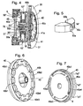
- the drive plate 40 illustrated in Figs. 2 and 4 to 7 , is, along one side 40a, formed with one or more (in this case four), grooves 40a1, 40a2, 40a3 and 40a4 connecting into a single circular line, the maximum arc length or length "x3" of which grooves are adapted to correspond to the selected maximized distance or travel distance labeled "x" in Fig. 14 , between an active position "x1 ", every intermediate position "x3" and an inactive position "x2" for the safety coupling 1 and in which distance "x3" coupling members 10, 20 can assume their engaged position via their activated and opposing friction surfaces 7, 7'.
- the drive plate 40 is formed, along its second side 40b, which is directed away from the first side 40a, according to Fig. 6 , with a substantially circular circumferential groove 40b1, this groove being formed with a number of inner notches or recesses facing away from the center 40', and outer notches or recesses 40b3 facing the center 40', and that these inner notches or recesses 40b2 and these outer notches or recesses 40b3 are adapted to open towards an intermediate, substantially circular narrow groove 40b4 (corresponding to groove 40b1).
- the notches or recesses 40b2, 40b3 of the other side 40b are adapted for engagement with a projection 50a on the trigger element 50', which is arranged in a movable radial manner between the drive plate 40 and hub plate 60.
- the trigger element 50' (and the counterweight element 50") exhibit a hole 50c in which the spring units 51', 51", and guide means 52', 52" are engaged.
- the spring assembly 51' exerts an inward-directed radial force on the trigger element 50' to compress it in an inward radial direction. At low rotation speed, the inwardly directed force is greater than the centrifugal force and the trigger element 50' is then held in its inner position whereby the projection 50a engages with the inner recesses 40b2 of the drive plate 40. At higher rotation speeds, the inwardly directed force is less than the centrifugal force and the trigger member 50' is then pressed toward its outer position whereby projection 50a engages with the outer recesses 40b3 of the drive plate 40.
- the centrifugal device 50 is thus adapted engage, via said projection 50a on the trigger element 50', at a low rotation speed of a first spring unit 51', with said inner notches or recesses 40b2, and at a high speed, by centrifugal forces, to engage with the outer, circumferentially distributed, notches or recesses or cutouts 40b3.
- This displacement is activated and accomplished by means of a centered return spring assembly 45.
- the centrifugal device 50 has two units which are movable by rotary motion in a radial manner from each other, a trigger element 50' and a counterweight element 50", with its projections, a projection 50a for unit 50, and is thereby guided in its radial movement by the radial grooves 50b in cooperation with radial rails 60a in a hub plate 60, according to Fig. 8 and 9 .
- This disc 60 has a cylindrical rim 60b and an outer groove 60c. This groove should be in a rigid engagement with a projection 41 a for the rotation of the disc 41.
- the units 50', 50' movable by rotary motion in a radial manner from each other are pressed, by the first and second spring units 51', 51" for the first and second devices 50', 50", to their inner starting position for engagement with notches or recesses 40b2 with projection 50a at low or no rotary motion, according to Fig. 4 , while the projection 50a is radially displaced, by centrifugal force and at a high rotation speed, for engagement with notches or recesses 40b3.
- Projection 50a on the movably arranged device 50' engages, via the drive plate 40, with the grooves 40b2 or 40b3 to form a switching function for the valve assembly 9, for example by means of a switch ring 41, which is adapted by forced rotation to switch and instantaneously open said valve assembly 9, to evacuate the cavity 8 and bring the coupling members 10, 20 to an inactive releasing position.
- the arrangement according the present invention functions in the following manner, as illustrated in Figs. 10 and 11 .
- coupling members 10, 20 When the torque transmitted from the first coupling member 10 to the second coupling member 20 exceeds a predetermined value, coupling members 10, 20 will be displaced relative to each other. This relative movement actuates the safety mechanism 3a through the rotation of switch ring 41, which is connected to the first coupling member 10 by receiving the top 9 of a valve assembly 9' in a peripherally arranged recess 42, relative to housing 30.
- the housing 30 is retained in position through its inflexible connection with the second coupling member 20.
- the rotary motion of the switch ring 41 is transferred to the hub plate 60 via interaction between the projection 41 a of the switch ring 41 and the groove 60c and the hub plate.
- the rotary motion is transferred from the hub plate 60 to the centrifugal device 50 through engagement between the rails 60a and grooves 50b.
- the projection 50a engages the inner notches of the drive plate 40b2 or outer notch 40b3.
- the rotary motion will thus be transmitted to the drive plate 40 which, via the grooves 40a1, 40a2, 40a3 and 40a4 are engaged with the stop screw 6.
- the return spring 45 Upon rotation of drive plate 40, the return spring 45 will be extended from its initial position, creating a biased return force acting on the drive plate 40.
- valve assembly 9 remains intact and safety arrangement 3b cannot be triggered.
- the trigger element 50' in the centrifugal device 50 is be pushed back in a radial inward direct by the spring assembly 51' to a position where the projection 50a is no longer engaged with notches 40b2, 40b3 in the drive plate 40, but rather is located in the intermediate groove 40b4.
- drive plate 40 is under the influence of the biasing force of the return spring 45, the drive plate 40 will automatically rotate back to its original position, as illustrated by the position "x1" in Fig. 7 , where the stop screw 6 must again run the maximum arcuate distance "x3" to before the safety arrangement is triggered.
- the radial position of the projection 50a depends, is as described above, on the rotation speed of the safety coupling 1. At a given speed, there is therefore a risk that the projection 50a will end up and remain in the intermediate groove 40b4 of the drive plate 40, which could lead to a failure of the safety arrangement 3b to be triggered, despite the fact that the rotary motion caused by the torque peaks between the coupling members 10, 20 exceeds the maximum arcuate distance "x3".
- drive plate 80 comprises on its first side 80a a plurality of circumferentially arranged ridges 80a1, 80a2, connecting in a circular line.
- the arcuate distance 80a3, 80a4 between the ridges 80a1, 80a2 corresponds to the selected maximum arcuate distance "x3" and in this case, the stop screw 6 is adapted to come into abutment against the ridges 80a1, 80a2 to thereby trigger the safety arrangement 3b.
- the drive plate 80 like drive plate 40, comprises a plurality of peripheral, inner and outer notches or recesses 80b1, 80b2 in a substantially circular arrangement.
- inner notches 80b1 are staggered in relation to outer notches 80b2, preferably by one half-step.
- notches 80b1, 80b2 are arranged such that no intermediate grooves are formed, i.e. the edges that define the notches 80b1, 80b2 substantially overlap in the radial direction so that the projection 50a of trigger element 50' is permitted to not end up in a radial position where it will not engage with a notch 80b1,80b2.
- notches 80b1, 80b2 are formed so that the tangential distribution of two successive inner notches 80b1 or outer notches 80b2 corresponds to the arcuate distance between the ridges 80a1, 80a2, i.e. to the selected maximum arcuate distance "x3".
- the function of the present invention is illustrated with reference to the guided safety arrangement 3b and the guiding safety mechanism 3a, which is adapted to allow a limited relative movement between the first 10 and second 20 coupling member in safety coupling 1 corresponding to a selected maximized distance "x 3" between their initial active position “x1 ", and their inactive position "x2", where a first A1, a second A2, and a third A3 operating cycle are illustrated in order to allow, for every operating cycle without a trigger, for the provision of a relative movement less than the maximized limited relative movement "x3" between the first and the second coupling member 10, 20 and for movement to and remaining in the initial position at every successive operating cycle.
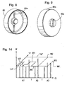
- Fig. 14 intends to provide a torque/time diagram to illustrate the temporal (t) distribution of selected and individual sections of more (not shown) continuous transmissions of torque which are below the initial value "x1" and provide no relative movement between the coupling members 10, 20, but whereby each torque transmission, in the form of short torque peaks, which when exceeding value "x1" provide a more or less relative movement, which in the event of a total displacement motion to and past the value "x2" disable the safety coupling 1.17.
- Fig. 14 illustrates three different operating cycles A1, A2 and A3, whereby the first A1 illustrates four discrete, time-distributed (t) and short transmissions of torque, whereby a first and a third torque peak cause no relative movement between the coupling members 10, 20 and a corresponding rotation of the disc 40, a second and a fourth torque peak each cause a short relative rotation within the value "x3" which are added to one another to the value "M1", whereupon the first operating cycle A1 concludes, and the value "M1" can then fall via safety mechanism 3a to the value "M0" or the value "x1".
- t time-distributed
- valve assembly 9 must be then replaced and the cavity 8 again filled with a medium 8' under pressure, such as an aqueous emulsion and/or oil.
- a medium 8' under pressure such as an aqueous emulsion and/or oil.
- Fig.2 uses reference numerals to show the orientation of and interaction between the two discs 40 and 60.
- each illustrated unit and/or circuit may be combined with any other device and/or circuit illustrated within the scope of achieving the desired technical function.
Landscapes
- Engineering & Computer Science (AREA)
- General Engineering & Computer Science (AREA)
- Mechanical Engineering (AREA)
- Physics & Mathematics (AREA)
- Fluid Mechanics (AREA)
- One-Way And Automatic Clutches, And Combinations Of Different Clutches (AREA)
- Transmission Devices (AREA)
- Mechanical Operated Clutches (AREA)
Claims (15)
- Sicherheitskupplung (1) mit einem zugehörigen Sicherheitsmechanismus (3a) und einer zugehörigen Sicherheitsanordnung (3b), miteinander zusammenhängend und/oder integriert gebildet, aufweisend eine Kupplungseinheit (1', 3), die dazu ausgebildet ist, bei einer Drehbewegung die Übertragung eines Drehmoments zwischen zwei koaxial orientierten Kupplungselementen (10, 20), einem ersten, antreibenden, inneren Kupplungselement (10) und einem zweiten, antreibenden äußeren Kupplungselement (20), zu ermöglichen, mit einer geformten Reibungsfläche (7, 7'), die zwischen dem inneren Kupplungselement (10) und dem äußeren Kupplungselement (20) gelegen ist, wobei das innere Kupplungselement (10) einen Hohlraum (8) neben der Reibungsfläche (7, 7') aufweist, der bei angelegtem Druck dazu ausgebildet ist, sich in die Richtung der Reibungsfläche (7, 7') auszudehnen;
wobei die Sicherheitskupplung (1) die zugehörige Sicherheitsanordnung (3b), die zu einer und in eine anfängliche Halteposition ("x1"), in welcher der Hohlraum (8) in einer ausgedehnten Position ist, oder zu einer und in eine inaktive Freigabeposition ("x2"), in welcher der Hohlraum (8) in einer nicht ausgedehnten Position ist, betätigbar ist, für die Kupplungseinheit (1', 3) aufweist;
wobei die betätigbare Sicherheitsanordnung (3b) dazu ausgebildet ist, wenn ein im Voraus gewähltes Drehmoment und eine relative Bewegung, die durch dieses Drehmoment zwischen dem ersten Kupplungselement (10) und dem zweiten Kupplungselement (20) verursacht wird, überschritten werden, durch den Sicherheitsmechanismus (3a) für eine Verschiebung aus der anfänglichen aktiven Position ("x1") zu der und in die inaktive Position ("x2") durch Evakuieren des Drucks aus dem Hohlraum (8) betätigbar zu sein;
wobei die Sicherheitsanordnung (3b) somit ausgebildet ist, eine begrenzte relative Bewegung zwischen dem ersten Kupplungselement (10) und dem zweiten Kupplungselement (20) entsprechend einer gewählten maximierten bogenförmigen Distanz ("x3") zwischen ihrer anfänglichen aktiven Position ("x1") und ihrer abschließenden inaktiven Position ("x2") zu ermöglichen; und
wobei die Sicherheitsanordnung (3b) ausgebildet ist, sofort die Kupplungseinheit (1') in ihre abschließende inaktive Position ("x2") zu betätigen, wenn sie ausgelöst ist,
dadurch gekennzeichnet, dass Mittel (40, 45), die der Sicherheitsanordnung (3b) und/oder dem Sicherheitsmechanismus (3a) zugeordnet sind, dazu ausgebildet sind, bei jedem abschließenden Betriebszyklus, einschließlich abschließender Betriebszyklen ohne Auslöser, der Sicherheitskupplung (1) den Sicherheitsmechanismus (3a) in die Richtung der anfänglichen aktiven Position ("x1") zurückzustellen und/oder zu verschieben, um wieder aus dieser aktiven Position die gewählte maximierte bogenförmige Distanz("x3") zwischen dem ersten Kupplungselement (10) und dem zweiten Kupplungselement (20) während eines anschließenden Betriebszyklus bereitzustellen. - Sicherheitskupplung nach Anspruch 1, wobei die anfängliche Position ("x1") gewählt ist, um in einen maximierten Bogenbereich ("x3") zu fallen, wo der Sicherheitsmechanismus (3a) abhängig von der gewählten Drehrichtung der zwei Kupplungselemente (10, 20) zwischen der anfänglichen aktiven Position ("x1") und der abschließenden inaktiven Position ("x2") und in entgegengesetzte Richtungen aus einer anfänglichen aktiven Position ("x1") verschoben werden kann.
- Sicherheitskupplung nach Anspruch 1 oder 2, wobei die begrenzte relative Bewegung zwischen dem ersten und zweiten Kupplungselement (10, 20) so gewählt ist, dass sie zumindest unter einer geringen Umdrehung liegt, zum Beispiel eine einzige Umdrehung oder ein Bruchteil einer Drehung, zum Beispiel eine Viertel Umdrehung ist.
- Sicherheitskupplung nach einem vorangehenden Anspruch, wobei eine verursachte relative Bewegung zwischen den Kupplungselementen (10, 20) über ein gewähltes, vorgegebenes, maximiertes Bewegungsmuster ("x3") hinaus die Kupplungselemente in eine inaktive Position ("x2") bringt.
- Sicherheitskupplung nach einem vorangehenden Anspruch, wobei der Hohlraum (8) mit einer Ventilgruppe (9) interagiert, die zum sofortigen Öffnen ausgebildet ist.
- Sicherheitskupplung nach Anspruch 5, wobei die Ventilgruppe (9) dazu ausgebildet ist, von Mitteln eines Schneidvorgangs geöffnet zu werden, die durch die Drehung einer benachbarten Scheibe (41) aktiviert werden.
- Sicherheitskupplung nach einem vorangehenden Anspruch, wobei die Mittel (40, 45) eine erste Scheibe (40; 80) aufweisen, die entlang ihrer einen Seite (40a, 80a) mit einer oder mehreren Umfangsrille(n) (40a1, 40a2, 40a3 und 40a4) oder Stegen (80a1, 80a2) gebildet ist, die zur Bildung einer einzigen kreisförmigen Linie verbunden sind, wobei die Länge der Rillen (40a1, 40a2, 40a3 und 40a4) oder die bogenförmige Distanz zwischen den Stegen (80a1, 80a2) dazu ausgebildet ist, der gewählten, maximierten, bogenförmigen Distanz ("x1" bis "x2") zwischen einer aktiven Position ("x1") und einer inaktiven Position ("x2") für die Kupplungseinheit (1') zu entsprechen, und wobei ein Stoppmittel (6) dazu ausgebildet ist, mit den Rillen (40a1, 40a2, 40a3 und 40a4) oder Stegen (80a1, 80a2) zu interagieren, um die Sicherheitsanordnung (3b) auszulösen.
- Sicherheitskupplung nach Anspruch 7, wobei die Scheibe (40, 80) entlang ihrer zweiten Seite (40b, 80b), die von der ersten Seite weg weist, mehrere innere Kerben, die zum Mittelpunkt (40') weisen, und mehrere zum Umfang weisende, äußere Kerben (40b3; 80b2) aufweist.
- Sicherheitskupplung nach Anspruch 8, wobei die Kerben (40b2, 40b3, 80b1, 80b2) anpassbar mit einer oder mehreren Einheit(en) (50', 50") einrastbar sind, die Vorsprünge (50a) aufweist (aufweisen), die in einer durch eine Zentrifugalvorrichtung (50), die auf Zentrifugalkräfte wirkt, radial beweglichen Weise angeordnet sind.
- Sicherheitskupplung nach Anspruch 9, wobei die Zentrifugalvorrichtung (50) dazu ausgebildet ist, bei geringer Drehzahl mit den inneren Kerben (40b2; 80b1) einzurasten und bei hoher Drehzahl mit den äußeren Kerben (40b3; 80b2) einzurasten.
- Sicherheitskupplung nach Anspruch 10, wobei die inneren Kerben (40b2) und äußeren Kerben (40b3) der Scheibe (40) dazu ausgebildet sind, sich zu einer dazwischenliegenden, im Wesentlichen kreisförmigen Rille (40b4) zu öffnen, und wenn die Einheiten (50', 50") mit den Vorsprüngen (50a) eine radiale Position einnehmen, die der Position der dazwischenliegenden Rille (40b4) entspricht, die Sicherheitsanordnung (3b) wieder die anfängliche aktive Position ("x1") der Kupplungsvorrichtung (1') einnimmt.
- Sicherheitskupplung nach Anspruch 10, wobei die inneren Kerben (80b1) und äußeren Kerben (80b2) der Scheibe (40) einen Halbschritt tangential in Bezug zueinander verschoben angeordnet sind.
- Sicherheitskupplung nach einem der Ansprüche 9-12, wobei die Zentrifugalvorrichtung (50) Einheiten hat, die durch Drehbewegung in radialer Weise voneinander (50', 50") mit zugeordneten Vorsprüngen (50a) bewegbar sind, und in ihrer Bewegung durch radiale Rillen (50b) geführt ist, die mit radialen Schienen (60a) auf einer Scheibe (60) interagieren.
- Sicherheitskupplung nach Anspruch 13, wobei die Einheiten (50', 50") durch erste und zweite Federeinheiten (51", 51') bei geringer oder keiner Drehbewegung in ihre inneren Startpositionen gepresst sind.
- Sicherheitskupplung nach Anspruch 9 oder 13, wobei Vorsprünge (50a) an den beweglich angeordneten Einheiten (50', 50") mit der Scheibe (40; 80) einrastbar sind, um mit dem Stoppmittel (6) einzurasten, das dazu ausgebildet ist, die Ventilgruppe (9) durch erzwungene Drehung zu öffnen und die Kupplungselemente in eine inaktive Freigabeposition ("x2") zu bringen.
Applications Claiming Priority (2)
| Application Number | Priority Date | Filing Date | Title |
|---|---|---|---|
| SE1100498A SE1100498A1 (sv) | 2011-06-27 | 2011-06-27 | Säkerhetskoppling |
| PCT/SE2012/050726 WO2013002722A1 (en) | 2011-06-27 | 2012-06-27 | Safety coupling |
Publications (2)
| Publication Number | Publication Date |
|---|---|
| EP2724040A1 EP2724040A1 (de) | 2014-04-30 |
| EP2724040B1 true EP2724040B1 (de) | 2016-08-10 |
Family
ID=46755072
Family Applications (1)
| Application Number | Title | Priority Date | Filing Date |
|---|---|---|---|
| EP12751628.4A Active EP2724040B1 (de) | 2011-06-27 | 2012-06-27 | Sicherheitskupplung |
Country Status (6)
| Country | Link |
|---|---|
| US (1) | US9267551B2 (de) |
| EP (1) | EP2724040B1 (de) |
| JP (1) | JP5671654B2 (de) |
| CN (1) | CN103688071B (de) |
| SE (1) | SE1100498A1 (de) |
| WO (1) | WO2013002722A1 (de) |
Families Citing this family (4)
| Publication number | Priority date | Publication date | Assignee | Title |
|---|---|---|---|---|
| CN103075437A (zh) * | 2013-01-22 | 2013-05-01 | 苏州市欧博锐自动化科技有限公司 | 一种联轴器型扭力限制器 |
| CN104749892B (zh) * | 2013-12-27 | 2017-02-01 | 上海微电子装备有限公司 | 一种具有碰撞保护功能的硅片边缘保护装置 |
| SE539962C2 (sv) | 2014-04-30 | 2018-02-13 | Voith Turbo Safeset Ab | Tryckbegränsande anordning för inneslutna utrymmen såsom hydrauliska säkerhetskopplingar |
| EP3144554A1 (de) * | 2015-09-21 | 2017-03-22 | Voith Patent GmbH | Sicherheitskupplung |
Family Cites Families (12)
| Publication number | Priority date | Publication date | Assignee | Title |
|---|---|---|---|---|
| US3237734A (en) | 1963-04-29 | 1966-03-01 | Ford Motor Co | Feedback controlled automatic clutch |
| GB1180357A (en) | 1967-11-21 | 1970-02-04 | Keller & Knappich Gmbh | Torque Overload Safety Device for Clutches |
| SE425515B (sv) * | 1978-06-15 | 1982-10-04 | Metalform Safeset Ab | Tryckmediepaverkad koppling |
| DE3720281A1 (de) * | 1987-06-19 | 1989-01-05 | Gelenkwellenbau Gmbh | Loesbare spannvorrichtung |
| SE463327B (sv) * | 1989-09-19 | 1990-11-05 | Metalform Safeset Ab | Koppling foer sammankoppling av tvaa koaxiella roterbara delar |
| DE9406199U1 (de) | 1994-04-14 | 1994-06-09 | Renk Tacke Gmbh, 86159 Augsburg | Druckentlastungsvorrichtung |
| SE525837C2 (sv) * | 2003-12-23 | 2005-05-10 | Voith Turbo Safeset Ab | Arrangemang vid en säkerhetskoppling |
| JP4476197B2 (ja) * | 2005-08-24 | 2010-06-09 | サンデン株式会社 | 動力伝達装置 |
| JP5531407B2 (ja) * | 2006-03-30 | 2014-06-25 | 株式会社ジェイテクト | トルクリミッタ |
| SE530706C2 (sv) * | 2006-12-27 | 2008-08-19 | Hudiksvalls Teknik Ct Ab | Koppling |
| SE531773C2 (sv) * | 2007-11-29 | 2009-08-04 | Voith Turbo Safeset Ab | Vridmomentsöverförande axel, såsom en så kallad kardanaxel |
| JP5151484B2 (ja) * | 2008-01-08 | 2013-02-27 | 株式会社ジェイテクト | トルクリミッタ |
-
2011
- 2011-06-27 SE SE1100498A patent/SE1100498A1/sv not_active Application Discontinuation
-
2012
- 2012-06-27 US US14/128,491 patent/US9267551B2/en active Active
- 2012-06-27 CN CN201280032078.0A patent/CN103688071B/zh active Active
- 2012-06-27 EP EP12751628.4A patent/EP2724040B1/de active Active
- 2012-06-27 JP JP2014518499A patent/JP5671654B2/ja active Active
- 2012-06-27 WO PCT/SE2012/050726 patent/WO2013002722A1/en not_active Ceased
Also Published As
| Publication number | Publication date |
|---|---|
| JP2014518364A (ja) | 2014-07-28 |
| US9267551B2 (en) | 2016-02-23 |
| CN103688071A (zh) | 2014-03-26 |
| US20140224611A1 (en) | 2014-08-14 |
| WO2013002722A1 (en) | 2013-01-03 |
| EP2724040A1 (de) | 2014-04-30 |
| CN103688071B (zh) | 2016-05-18 |
| SE1100498A1 (sv) | 2012-12-28 |
| JP5671654B2 (ja) | 2015-02-18 |
Similar Documents
| Publication | Publication Date | Title |
|---|---|---|
| US9267551B2 (en) | Safety coupling | |
| JP5854900B2 (ja) | 動力伝達装置 | |
| JP6836335B2 (ja) | 駆動アクチュエータ | |
| CA2837072C (en) | Dual direction clutch-brake | |
| US4694943A (en) | Ground clutch assembly with dynamic engagement and disengagement | |
| JP5930749B2 (ja) | 乗客コンベア | |
| AU2009231490A1 (en) | Protective system for machine tools | |
| JP2925640B2 (ja) | 安全装置 | |
| US7168533B2 (en) | Rotor brake as well as rotor and rotary-wing aircraft with such a rotor brake | |
| EP2596261A1 (de) | Zahnrad-hydraulikkolbenbremse | |
| JP2017155883A (ja) | 動力伝達装置 | |
| CN106365011A (zh) | 制动力不变的限速保护装置 | |
| JP2665467B2 (ja) | リターダ制御装置 | |
| JP6785847B2 (ja) | 安全継手、安全継手に用いられる遠心装置および安全継手を有する駆動ライン | |
| EP0287099B1 (de) | Mit einer Parkbremse versehener hydraulischer Retarder | |
| US4997071A (en) | Automatic control system for a clutch coupling two rotating shafts | |
| CN102815650A (zh) | 防坠落装置 | |
| CN103089871A (zh) | 电磁制动器 | |
| KR101653217B1 (ko) | 클러치 장치를 구비한 리타더 및 그 제어 방법 | |
| EP1702823B1 (de) | Bremsanlage mit Primär- und Sekundärbremsen | |
| KR102616541B1 (ko) | 차량용 제동장치 | |
| US6460672B1 (en) | Safety device for torque limiter | |
| KR100383921B1 (ko) | 오토 크루즈 장치의 클러치 시스템 | |
| CN103441610A (zh) | 一种制动电机 | |
| CN120898085A (zh) | 离合器装置 |
Legal Events
| Date | Code | Title | Description |
|---|---|---|---|
| PUAI | Public reference made under article 153(3) epc to a published international application that has entered the european phase |
Free format text: ORIGINAL CODE: 0009012 |
|
| 17P | Request for examination filed |
Effective date: 20140127 |
|
| AK | Designated contracting states |
Kind code of ref document: A1 Designated state(s): AL AT BE BG CH CY CZ DE DK EE ES FI FR GB GR HR HU IE IS IT LI LT LU LV MC MK MT NL NO PL PT RO RS SE SI SK SM TR |
|
| DAX | Request for extension of the european patent (deleted) | ||
| 17Q | First examination report despatched |
Effective date: 20150610 |
|
| GRAP | Despatch of communication of intention to grant a patent |
Free format text: ORIGINAL CODE: EPIDOSNIGR1 |
|
| INTG | Intention to grant announced |
Effective date: 20160216 |
|
| GRAS | Grant fee paid |
Free format text: ORIGINAL CODE: EPIDOSNIGR3 |
|
| GRAA | (expected) grant |
Free format text: ORIGINAL CODE: 0009210 |
|
| AK | Designated contracting states |
Kind code of ref document: B1 Designated state(s): AL AT BE BG CH CY CZ DE DK EE ES FI FR GB GR HR HU IE IS IT LI LT LU LV MC MK MT NL NO PL PT RO RS SE SI SK SM TR |
|
| REG | Reference to a national code |
Ref country code: GB Ref legal event code: FG4D |
|
| REG | Reference to a national code |
Ref country code: CH Ref legal event code: EP Ref country code: AT Ref legal event code: REF Ref document number: 819345 Country of ref document: AT Kind code of ref document: T Effective date: 20160815 |
|
| REG | Reference to a national code |
Ref country code: IE Ref legal event code: FG4D |
|
| REG | Reference to a national code |
Ref country code: DE Ref legal event code: R096 Ref document number: 602012021520 Country of ref document: DE |
|
| REG | Reference to a national code |
Ref country code: SE Ref legal event code: TRGR |
|
| REG | Reference to a national code |
Ref country code: LT Ref legal event code: MG4D |
|
| REG | Reference to a national code |
Ref country code: NL Ref legal event code: MP Effective date: 20160810 |
|
| REG | Reference to a national code |
Ref country code: AT Ref legal event code: MK05 Ref document number: 819345 Country of ref document: AT Kind code of ref document: T Effective date: 20160810 |
|
| PG25 | Lapsed in a contracting state [announced via postgrant information from national office to epo] |
Ref country code: FI Free format text: LAPSE BECAUSE OF FAILURE TO SUBMIT A TRANSLATION OF THE DESCRIPTION OR TO PAY THE FEE WITHIN THE PRESCRIBED TIME-LIMIT Effective date: 20160810 Ref country code: NO Free format text: LAPSE BECAUSE OF FAILURE TO SUBMIT A TRANSLATION OF THE DESCRIPTION OR TO PAY THE FEE WITHIN THE PRESCRIBED TIME-LIMIT Effective date: 20161110 Ref country code: HR Free format text: LAPSE BECAUSE OF FAILURE TO SUBMIT A TRANSLATION OF THE DESCRIPTION OR TO PAY THE FEE WITHIN THE PRESCRIBED TIME-LIMIT Effective date: 20160810 Ref country code: IS Free format text: LAPSE BECAUSE OF FAILURE TO SUBMIT A TRANSLATION OF THE DESCRIPTION OR TO PAY THE FEE WITHIN THE PRESCRIBED TIME-LIMIT Effective date: 20161210 Ref country code: LT Free format text: LAPSE BECAUSE OF FAILURE TO SUBMIT A TRANSLATION OF THE DESCRIPTION OR TO PAY THE FEE WITHIN THE PRESCRIBED TIME-LIMIT Effective date: 20160810 Ref country code: RS Free format text: LAPSE BECAUSE OF FAILURE TO SUBMIT A TRANSLATION OF THE DESCRIPTION OR TO PAY THE FEE WITHIN THE PRESCRIBED TIME-LIMIT Effective date: 20160810 Ref country code: NL Free format text: LAPSE BECAUSE OF FAILURE TO SUBMIT A TRANSLATION OF THE DESCRIPTION OR TO PAY THE FEE WITHIN THE PRESCRIBED TIME-LIMIT Effective date: 20160810 Ref country code: IT Free format text: LAPSE BECAUSE OF FAILURE TO SUBMIT A TRANSLATION OF THE DESCRIPTION OR TO PAY THE FEE WITHIN THE PRESCRIBED TIME-LIMIT Effective date: 20160810 |
|
| PG25 | Lapsed in a contracting state [announced via postgrant information from national office to epo] |
Ref country code: GR Free format text: LAPSE BECAUSE OF FAILURE TO SUBMIT A TRANSLATION OF THE DESCRIPTION OR TO PAY THE FEE WITHIN THE PRESCRIBED TIME-LIMIT Effective date: 20161111 Ref country code: PL Free format text: LAPSE BECAUSE OF FAILURE TO SUBMIT A TRANSLATION OF THE DESCRIPTION OR TO PAY THE FEE WITHIN THE PRESCRIBED TIME-LIMIT Effective date: 20160810 Ref country code: LV Free format text: LAPSE BECAUSE OF FAILURE TO SUBMIT A TRANSLATION OF THE DESCRIPTION OR TO PAY THE FEE WITHIN THE PRESCRIBED TIME-LIMIT Effective date: 20160810 Ref country code: PT Free format text: LAPSE BECAUSE OF FAILURE TO SUBMIT A TRANSLATION OF THE DESCRIPTION OR TO PAY THE FEE WITHIN THE PRESCRIBED TIME-LIMIT Effective date: 20161212 Ref country code: AT Free format text: LAPSE BECAUSE OF FAILURE TO SUBMIT A TRANSLATION OF THE DESCRIPTION OR TO PAY THE FEE WITHIN THE PRESCRIBED TIME-LIMIT Effective date: 20160810 Ref country code: ES Free format text: LAPSE BECAUSE OF FAILURE TO SUBMIT A TRANSLATION OF THE DESCRIPTION OR TO PAY THE FEE WITHIN THE PRESCRIBED TIME-LIMIT Effective date: 20160810 |
|
| PG25 | Lapsed in a contracting state [announced via postgrant information from national office to epo] |
Ref country code: EE Free format text: LAPSE BECAUSE OF FAILURE TO SUBMIT A TRANSLATION OF THE DESCRIPTION OR TO PAY THE FEE WITHIN THE PRESCRIBED TIME-LIMIT Effective date: 20160810 Ref country code: RO Free format text: LAPSE BECAUSE OF FAILURE TO SUBMIT A TRANSLATION OF THE DESCRIPTION OR TO PAY THE FEE WITHIN THE PRESCRIBED TIME-LIMIT Effective date: 20160810 |
|
| REG | Reference to a national code |
Ref country code: DE Ref legal event code: R097 Ref document number: 602012021520 Country of ref document: DE |
|
| PG25 | Lapsed in a contracting state [announced via postgrant information from national office to epo] |
Ref country code: BE Free format text: LAPSE BECAUSE OF FAILURE TO SUBMIT A TRANSLATION OF THE DESCRIPTION OR TO PAY THE FEE WITHIN THE PRESCRIBED TIME-LIMIT Effective date: 20160810 Ref country code: DK Free format text: LAPSE BECAUSE OF FAILURE TO SUBMIT A TRANSLATION OF THE DESCRIPTION OR TO PAY THE FEE WITHIN THE PRESCRIBED TIME-LIMIT Effective date: 20160810 Ref country code: CZ Free format text: LAPSE BECAUSE OF FAILURE TO SUBMIT A TRANSLATION OF THE DESCRIPTION OR TO PAY THE FEE WITHIN THE PRESCRIBED TIME-LIMIT Effective date: 20160810 Ref country code: SK Free format text: LAPSE BECAUSE OF FAILURE TO SUBMIT A TRANSLATION OF THE DESCRIPTION OR TO PAY THE FEE WITHIN THE PRESCRIBED TIME-LIMIT Effective date: 20160810 Ref country code: BG Free format text: LAPSE BECAUSE OF FAILURE TO SUBMIT A TRANSLATION OF THE DESCRIPTION OR TO PAY THE FEE WITHIN THE PRESCRIBED TIME-LIMIT Effective date: 20161110 Ref country code: SM Free format text: LAPSE BECAUSE OF FAILURE TO SUBMIT A TRANSLATION OF THE DESCRIPTION OR TO PAY THE FEE WITHIN THE PRESCRIBED TIME-LIMIT Effective date: 20160810 |
|
| PLBE | No opposition filed within time limit |
Free format text: ORIGINAL CODE: 0009261 |
|
| STAA | Information on the status of an ep patent application or granted ep patent |
Free format text: STATUS: NO OPPOSITION FILED WITHIN TIME LIMIT |
|
| REG | Reference to a national code |
Ref country code: FR Ref legal event code: PLFP Year of fee payment: 6 |
|
| 26N | No opposition filed |
Effective date: 20170511 |
|
| PG25 | Lapsed in a contracting state [announced via postgrant information from national office to epo] |
Ref country code: SI Free format text: LAPSE BECAUSE OF FAILURE TO SUBMIT A TRANSLATION OF THE DESCRIPTION OR TO PAY THE FEE WITHIN THE PRESCRIBED TIME-LIMIT Effective date: 20160810 |
|
| PG25 | Lapsed in a contracting state [announced via postgrant information from national office to epo] |
Ref country code: MC Free format text: LAPSE BECAUSE OF FAILURE TO SUBMIT A TRANSLATION OF THE DESCRIPTION OR TO PAY THE FEE WITHIN THE PRESCRIBED TIME-LIMIT Effective date: 20160810 |
|
| REG | Reference to a national code |
Ref country code: CH Ref legal event code: PL |
|
| REG | Reference to a national code |
Ref country code: IE Ref legal event code: MM4A |
|
| PG25 | Lapsed in a contracting state [announced via postgrant information from national office to epo] |
Ref country code: CH Free format text: LAPSE BECAUSE OF NON-PAYMENT OF DUE FEES Effective date: 20170630 Ref country code: LI Free format text: LAPSE BECAUSE OF NON-PAYMENT OF DUE FEES Effective date: 20170630 Ref country code: IE Free format text: LAPSE BECAUSE OF NON-PAYMENT OF DUE FEES Effective date: 20170627 Ref country code: LU Free format text: LAPSE BECAUSE OF NON-PAYMENT OF DUE FEES Effective date: 20170627 |
|
| REG | Reference to a national code |
Ref country code: FR Ref legal event code: PLFP Year of fee payment: 7 |
|
| PG25 | Lapsed in a contracting state [announced via postgrant information from national office to epo] |
Ref country code: MT Free format text: LAPSE BECAUSE OF NON-PAYMENT OF DUE FEES Effective date: 20170627 |
|
| PG25 | Lapsed in a contracting state [announced via postgrant information from national office to epo] |
Ref country code: AL Free format text: LAPSE BECAUSE OF FAILURE TO SUBMIT A TRANSLATION OF THE DESCRIPTION OR TO PAY THE FEE WITHIN THE PRESCRIBED TIME-LIMIT Effective date: 20160810 |
|
| PG25 | Lapsed in a contracting state [announced via postgrant information from national office to epo] |
Ref country code: HU Free format text: LAPSE BECAUSE OF FAILURE TO SUBMIT A TRANSLATION OF THE DESCRIPTION OR TO PAY THE FEE WITHIN THE PRESCRIBED TIME-LIMIT; INVALID AB INITIO Effective date: 20120627 |
|
| PG25 | Lapsed in a contracting state [announced via postgrant information from national office to epo] |
Ref country code: CY Free format text: LAPSE BECAUSE OF NON-PAYMENT OF DUE FEES Effective date: 20160810 |
|
| PG25 | Lapsed in a contracting state [announced via postgrant information from national office to epo] |
Ref country code: MK Free format text: LAPSE BECAUSE OF FAILURE TO SUBMIT A TRANSLATION OF THE DESCRIPTION OR TO PAY THE FEE WITHIN THE PRESCRIBED TIME-LIMIT Effective date: 20160810 |
|
| PG25 | Lapsed in a contracting state [announced via postgrant information from national office to epo] |
Ref country code: TR Free format text: LAPSE BECAUSE OF FAILURE TO SUBMIT A TRANSLATION OF THE DESCRIPTION OR TO PAY THE FEE WITHIN THE PRESCRIBED TIME-LIMIT Effective date: 20160810 |
|
| PGFP | Annual fee paid to national office [announced via postgrant information from national office to epo] |
Ref country code: DE Payment date: 20250618 Year of fee payment: 14 |
|
| PGFP | Annual fee paid to national office [announced via postgrant information from national office to epo] |
Ref country code: GB Payment date: 20250618 Year of fee payment: 14 |
|
| PGFP | Annual fee paid to national office [announced via postgrant information from national office to epo] |
Ref country code: FR Payment date: 20250624 Year of fee payment: 14 |
|
| PGFP | Annual fee paid to national office [announced via postgrant information from national office to epo] |
Ref country code: SE Payment date: 20250618 Year of fee payment: 14 |