EP2723204B1 - Clamp assembly and apparel containing same - Google Patents
Clamp assembly and apparel containing same Download PDFInfo
- Publication number
- EP2723204B1 EP2723204B1 EP12733277.3A EP12733277A EP2723204B1 EP 2723204 B1 EP2723204 B1 EP 2723204B1 EP 12733277 A EP12733277 A EP 12733277A EP 2723204 B1 EP2723204 B1 EP 2723204B1
- Authority
- EP
- European Patent Office
- Prior art keywords
- clamp
- band
- cover
- resilient cover
- clamp assembly
- Prior art date
- Legal status (The legal status is an assumption and is not a legal conclusion. Google has not performed a legal analysis and makes no representation as to the accuracy of the status listed.)
- Active
Links
Images

Classifications
-
- A—HUMAN NECESSITIES
- A41—WEARING APPAREL
- A41D—OUTERWEAR; PROTECTIVE GARMENTS; ACCESSORIES
- A41D13/00—Professional, industrial or sporting protective garments, e.g. surgeons' gowns or garments protecting against blows or punches
- A41D13/0002—Details of protective garments not provided for in groups A41D13/0007 - A41D13/1281
- A41D13/0005—Joints
-
- A—HUMAN NECESSITIES
- A41—WEARING APPAREL
- A41D—OUTERWEAR; PROTECTIVE GARMENTS; ACCESSORIES
- A41D19/00—Gloves
- A41D19/0055—Plastic or rubber gloves
- A41D19/0082—Details
- A41D19/0089—Joints between glove and cuff or garment
-
- Y—GENERAL TAGGING OF NEW TECHNOLOGICAL DEVELOPMENTS; GENERAL TAGGING OF CROSS-SECTIONAL TECHNOLOGIES SPANNING OVER SEVERAL SECTIONS OF THE IPC; TECHNICAL SUBJECTS COVERED BY FORMER USPC CROSS-REFERENCE ART COLLECTIONS [XRACs] AND DIGESTS
- Y10—TECHNICAL SUBJECTS COVERED BY FORMER USPC
- Y10T—TECHNICAL SUBJECTS COVERED BY FORMER US CLASSIFICATION
- Y10T24/00—Buckles, buttons, clasps, etc.
- Y10T24/44—Clasp, clip, support-clamp, or required component thereof
- Y10T24/44239—Encircling gripping member including semirigid band and operator for tightening
-
- Y—GENERAL TAGGING OF NEW TECHNOLOGICAL DEVELOPMENTS; GENERAL TAGGING OF CROSS-SECTIONAL TECHNOLOGIES SPANNING OVER SEVERAL SECTIONS OF THE IPC; TECHNICAL SUBJECTS COVERED BY FORMER USPC CROSS-REFERENCE ART COLLECTIONS [XRACs] AND DIGESTS
- Y10—TECHNICAL SUBJECTS COVERED BY FORMER USPC
- Y10T—TECHNICAL SUBJECTS COVERED BY FORMER US CLASSIFICATION
- Y10T24/00—Buckles, buttons, clasps, etc.
- Y10T24/44—Clasp, clip, support-clamp, or required component thereof
- Y10T24/44641—Clasp, clip, support-clamp, or required component thereof having gripping member formed from, biased by, or mounted on resilient member
Definitions
- This invention relates to a device useful for attaching of one item of clothing to another item of clothing. It is especially useful in attaching protective gloves to the sleeves of protective garments.
- Patent document US 7,434,270 B1 discloses a protective garment having gloves at the bottom of sleeve portions which can be quickly attached and detached.
- the gloves contain an attachment ring which sealingly mates with a respective attachment ring on the sleeve portions by a bayonet attachment.
- Patent document US 1,377,648 A discloses a clamping bracelet for use in connection with the wrist portion of a mitten or glove.
- Patent document US 7,448,093 B1 discloses a safety suit for the gas- or liquid-proof connection of gloves or boots with arm or leg openings of the safety suit having a support ring made of a solid material.
- This invention relates to a clamp assembly
- a clamp assembly comprising a clamp including a circular band and a tubular resilient cover having a hollow body, wherein the clamp is positioned in the hollow and is encased on all sides by the resilient cover, wherein the cover has an opening for operating the clamp, wherein the clamp includes a screw housing mounted to the band, and a worm screw disposed in the screw housing for engaging and positioning the band, and wherein the resilient cover comprises artificial or natural rubber.
- This invention also relates to a garment comprising a glove layer attached to a sleeve layer by a clamp assembly and a support ring, the clamp assembly comprising a clamp including a circular band and a tubular resilient cover having a hollow body, wherein the clamp is positioned in the hollow and is encased on all sides by the resilient cover, wherein the clamp compresses the sleeve layer and glove layer between the clamp assembly and the support ring, wherein the cover has an opening for operating the clamp, wherein the clamp includes a screw housing mounted to the band, and a worm screw disposed in the screw housing for engaging and positioning the band.
- This invention further relates to a process for attaching a first item of clothing to a second item of clothing, each item of clothing comprising at least one material layer, comprising the steps of:
- This invention relates to a clamp assembly
- a clamp assembly comprising a clamp including a circular band and a tubular resilient cover having a hollow body, wherein the clamp is positioned in the hollow and is encased on all sides by the resilient cover, wherein the cover has an opening for operating the clamp, wherein the clamp includes a screw housing mounted to the band, and a worm screw disposed in the screw housing for engaging and positioning the band, and wherein the resilient cover comprises artificial or natural rubber.
- this invention relates to a removable clamp assembly for sealing together two items of clothing, the clamp assembly comprising a clamp including a band, a screw housing mounted to the band, and a worm screw disposed in the screw housing for engaging and positioning the band, the clamp encased in a tubular resilient cover, the resilient cover having an opening to operate the worm screw. It is especially useful for sealing protective gloves to the sleeves of protective garments.
- the clamp assembly can provide a removable leak-proof seal between the glove and sleeve without the use of duct tape or rubber bands.
- the clamp assembly conceivably has other uses, such as sealing footwear to the legs of a protective garment; or sealing other items of clothing, such as access panels, to the protective garment for other equipment.
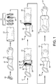
- Figure 1 is a representation of the prior art method of attaching a glove to a sleeve.
- Support ring 11 is inserted into rubber glove 12 as shown, and the fingers of the glove are further inserted into the inverted end of a sleeve 13 of a protective garment.
- the support ring can be made by cutting a thin ring of about 1 to 3 inches (2.5 to 7.6 cm) in length from rigid PVC tubing having a nominal diameter of from about 3 to 6 inches (7.6 to 15.2 cm); however, any relatively rigid ring could be used.
- An assortment of attachment devices 14 including rubber bands 15 and hose clip 16 are then used to attach the glove to the sleeve.
- one or two rubber bands 15 are first positioned on top of the end of the sleeve 13 , compressing the sleeve end onto the rubber glove 12 at the position of the support ring 11 . These first one or two rubber bands protect the protective garment fabric from the surface of the hose clip, which is installed over the rubber bands. The hose clip is then tightened to attach the sleeve end to the rubber glove by further compressing the sleeve and glove layers between the hose clip and the support ring. After the hose clip is tightened, normally with a tool (not shown), one or more additional rubber bands 15 then are installed over the hose clip as shown in 18 .
- the sleeve 13 is re-inverted to expose the glove 12 .
- the steps must be reversed, inverting the sleeve, followed by removing first the duct tape, then the rubber bands, and then loosening the hose clip with a tool.
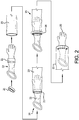
- FIG. 2 is one representation of the use of a clamp assembly for attaching two items of clothing together; in this illustration again a glove is attached to a sleeve.
- support ring 21 is inserted into rubber glove 22 as shown, and the fingers of the glove are further inserted into the inverted end of a sleeve 23 of a protective garment. The end of the sleeve 23 is then positioned on the rubber glove 22 and adjacent the support ring 21 .
- clamp assembly 26 comprising a clamp encased on all sides by, and positioned in the hollow of, a tubular sleeve cover is then positioned on top of the end of the sleeve 23 in line with the support ring 21 .
- the clamp is then tightened, normally with a tool, compressing the sleeve and glove layers (along with that part of the cover that is between the sleeve and the clamp) between the clamp in the clamp assembly and the support ring. Finally, the sleeve 23 is re-inverted to expose the glove 22 .
- a removable clamp is used in the clamp assembly, to detach the glove from the sleeve, or adjust the glove on the sleeve, all that is needed is to invert the sleeve and loosen the clamp, again normally using a tool.
- FIG. 3 is a representation of a preferred clamp assembly 31 .
- This version has the advantage of being removable. It is comprised of a clamp that is a type of hose clip; the clamp includes a band 32 , a screw housing 33 mounted to the band and having a worm screw disposed in the screw housing for engaging and positioning the band.
- the band has a first end that is attached to the screw housing and a second free end having slots; the free end circles around and is inserted into and through the screw housing to form a banded ring, with the threads of the worm screw engaging the slots in the band for positioning the band as desired; i.e., to tighten or loosen the band.
- the worm screw is typically provided with a slotted and/or hex head 34 for turning the worm screw and tightening and loosening the band.
- the clamp is encased in a tubular resilient cover 35 , the resilient cover having an opening to operate the band via the worm screw.
- the tubular resilient cover 35 as shown in Figure 3 can have a D-shaped cross-section, meaning that the interior surface of the cover has a flat surface 36 of a size compatible with the width of the band, as shown by the cross section 38 in Figure 4A .
- the tubular resilient cover can have many different shapes including square or rectangular, round, oval or irregular, as in the D-shape. In addition to the most preferred D-shape cross section, other preferred cross-sections include the round cross section 39 shown in Figure 4B , and the oval cross section 40 shown in Figure 4C .
- the resilient cover is in the form of a continuous hollow toroidal body of an elastomeric material, and if the clamp requires such, additionally having a small slit for the insertion of a tool to operate the clamp.
- the resilient cover is in the form of an elastomeric hollow tube having two ends, with one end inserted into the other to form a hollow toroidal body.
- the resilient cover is made from an artificial or natural rubber or other elastomeric material.
- Useful rubber, elastomeric and other materials include those having the following nomenclature from ASTM Standard D1418-06 "Standard Practice for Rubber and Rubber Latices" of: EPDM (terpolymer of ethylene, propylene, and a diene with the residual unsaturated portion of the diene in the side chain); IR (synthetic isoprene); BIIR (bromo-isobutene-isoprene); BR (butadiene); CIIR (chloro-isobutene-isoprene); CR (chloroprene); CSM (chloro-sulfonyl-polyethylene); ECO (ethylene oxide (oxirane) and chloromethyl oxirane (epichlorohydrin copolymer)); EPM (copolymers of ethylene and propylene), FKM (fluoro rubber of the polymethylene type that utilizes vinylidene fluoride as a comonomer and has
- the resilient cover has a useful shelf life that at least equals and preferably exceeds the shelf life of the fabric used in the garment being sealed, which is typically at least 10 years based on current ASTM standards.
- the resilient cover has a thickness that is preferably at least 0.04 inches (0.10 cm) for the portion compressed between the band of the clamp and the sleeve. In some embodiments the resilient cover has a thickness that is preferably at least 0.06 inches (0.15 cm) for the portion that covers the top of the band, the worm screw, and the worm screw housing. The actual thickness and hardness (durometer) of the resilient cover is selected such that the cover has adequate durability to prevent any abrasion from the clamp to wear through the cover. In some preferred embodiments, the resilient tubular cover is separate from the clamp so that either the cover or the clamp can be replaced individually.
- the clamp includes a circular band that can be tightened to compress the resilient cover, and at least two items of clothing together on a support.
- the circular band can be tightened and loosened.
- the version according to the invention is referred to as a hose clip or hose clamp and has a worm screw and screw housing as previously described.
- the band, worm screw, and screw housing are normally made of a durable metal; however, other materials could conceivably be used.
- Other types of banded clamps can be used, and they need not be easily removable if such functionality is not required.
- the circular banded clamp could be in the form of the fastener type known as a cable tie, also known as a zip tie and tie-wrap.
- Such fasteners can include a sturdy nylon tape with an integrated gear rack, which forms the circular band, the fastener further having one pointed end and one end having a type of ratchet within a small open case. Once the pointed tip of the cable tie has been pulled through the case and past the ratchet, forming the circular band, it is prevented from being pulled back; the resulting loop may only be pulled tighter.
- Such bands would normally have to be cut to be removed, and the opening in the resilient cover could be use to accomplish this.
- banded clamps include, for example, those that can be tightened by crimping; snapper-type clamps; hose clips and other clamps having a quick-release band; "herbie” or “HCL” clips; and hose clamp types designated A, B, C, D, E, and F by the Society of Automotive Engineers Standard J536b that include various tightening mechanisms and bands, including those using one or more wires as the band.
- the clamp is positioned in the hollow of the tubular resilient cover and is encased on all sides by that cover.
- encased it is meant the clamp, including the circular band, is effectively enclosed by or encapsulated by the resilient cover, except for an opening in the cover if needed for the insertion of a tool to operate the band.
- the clamp including the circular band is a hose clip having a screw housing and worm screw, all positioned in the hollow of the cover and encased on all sides by that cover, having an opening for the insertion of a tool to operate the worm screw.
- this opening can be a slot 37 cut into the resilient cover.
- a tool such as an appropriately sized metric or SAE nut driver, can be inserted under the cover to mechanically engage the hex head of the worm screw for tightening or loosening the screw.
- other types of screw driver can be used, but care must be taken to avoid puncturing the resilient cover or even the protective garment fabric with the tool.
- the tubular resilient cover is a continuous hollow tube, except for the opening formed by the slit; in some other embodiments the tubular resilient cover is a tube having first and second ends and the opening in the cover is formed by inserting a first end of the tube into the second end, as shown in Figure 5 .
- the tubular resilient cover is in the form of a flexible tube having two opposing ends. One end 41 of the resilient cover is inserted into the other end 42 of the resilient cover an adequate distance to maintain one end within the other end. Because the diameter of the two ends is the same, the surface of the inserted end 41 is slightly bowed or crimped, forming an opening 43 , with which a tool could be inserted, for example, to operate the worm screw.
- the clamp can be installed in the hollow of the resilient cover by inserting one end of the band from the clamp into the hollow of the tubular cover, threading the band through the cover and then reattaching the band to form the circular clamp. If the clamp is a hose clip, then similarly the free end of the band is disengaged from the screw housing, and both the band and screw housing are inserted and threaded through the hollow in the tubular cover, and then reattached to form the circular clamp; then one end of the tubular cover is inserted into the other end of the tubular cover to form the completed clamp assembly.
- the slot can be used to assemble the clamp assembly.
- the clamp including the band and screw housing containing the worm screw can be inserted through the slot in the resilient cover by loosening the band until the free end is backed entirely out of the screw housing, forming an opening in the banded ring.
- the free end of the band and the screw housing can then be inserted into the slot of the resilient cover, and threaded around the annular space.
- the free end is then inserted back into the screw housing and the worm screw tightened to re-form the banded clamp inside the resilient cover.
- a cable-tie like clamp could also be installed in a similar manner without requiring the use of a tool.
- Figure 6 is a representation of one type of a preferred clamp assembly 31 using the cover arrangement illustrated in Figure 5.
- Figure 6 like Figure 3 , is comprised of a clamp that is a type of hose clip; the clamp includes a band 32 , a screw housing 33 mounted to the band and having a worm screw disposed in the screw housing for engaging and positioning the band.
- the band has a first end that is attached to the screw housing and a second free end having slots that circles around and is inserted into and through the screw housing to form a banded ring, with the threads of the worm screw engaging the slots in the band and positioning the band as desired to tighten or loosen the band.
- the worm screw is typically provided with a slotted hex head 34 for turning the worm screw and tightening and loosening the band.
- the opening is preferably conveniently located or positioned such that the clamp can be operated with a tool. Further, care is taken to ensure the slot is positioned such that the free end or any portion of the band does not extend through the opening.
- the opening is positioned between the free end of the band and the screw housing in the case of a hose clip; or between the free end of the band and ratchet in the case of a cable-tie like band.
- This invention also relates to a garment comprising a glove layer attached to a sleeve layer by a clamp assembly and a support ring, the clamp assembly comprising a clamp including a circular band and a tubular resilient cover having a hollow body wherein the clamp is positioned in the hollow and is encased on all sides by the resilient cover, wherein the clamp compresses the sleeve layer and glove layer between the clamp assembly and the support ring, wherein the cover has an opening for operating the clamp, wherein the clamp includes a screw housing mounted to the band, and a worm screw disposed in the screw housing for engaging and positioning the band.
- the garment is a protective garment comprising a glove attached to a sleeve by a removable clamp assembly, the clamp assembly comprising a clamp including a band, a screw housing mounted to the band, and a worm screw disposed in the screw housing for engaging and positioning the band, the clamp encased in a tubular resilient cover, the resilient cover having an opening to operate the worm screw.
- the sleeve is a part of a Level A, B, C or D protective garment.
- Level A garments are used in situations that require the highest level of skin, respiratory, and eye protection, and are generally totally encapsulating vapor protective garments.
- Level B garments are used in situations that require the highest level of respiratory protection but a lesser level of skin protection is needed.
- Level C garments are used in situations where atmospheric contaminants, liquid splashes, and other direct contact will not adversely affect or be absorbed by any exposed skin.
- Level D garments are used in situations where contamination is only a nuisance. There may be some instances where combinations of protective apparel rated for A, B, C, or D level may be used together.
- the sleeve is part of an encapsulating chemical-resistant suit, in some embodiments it is part of coveralls, or part of any type of shirt or coat or pants or combination garment.
- Useful gloves include chemical resistant gloves made of materials such as the rubbers and elastomeric materials previously cited for the resilient cover, along with such materials as polyvinyl alcohol and polyvinylchloride.
- the glove can include a chemical resistant liner in the form of proprietary protective garment fabrics, barrier fabrics, laminates, and films; and this liner is sealed along with the glove and the sleeve with the clamp assembly.
- the material forming the sleeves in these garments can vary widely and can include nonwovens and woven fabrics and laminates of such materials with films.
- the sleeve and garment material is a multilayer film and nonwoven laminate.
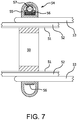
- FIG 7 is one possible cross-sectional representation of the clamp assembly installed as generally represented by 25 in Figure 2 .
- Support ring 50 is positioned inside both rubber glove 52 and a chemical protective liner 51 as shown.
- the end of sleeve 53 of a protective garment is adjacent and generally aligned with the support ring, with some overlap.
- the clamp assembly 54 comprises a clamp, including a band 56 and screw housing with hex head worm screw 57 mounted to the band.
- the clamp is encased in the hollow of tubular resilient cover 55 having a D-shaped cross-section, the straight side of the cover forming the innermost surface.
- the clamp assembly is positioned on top of the end of the sleeve 53 in line with the support ring 50 . After the clamp assembly is installed and tightened, the sleeve 53 is then inverted over the clamp assembly as shown in the last step in Figure 2 . All of the other features of the clamp assembly previously discussed herein can be used with the garment containing the clamp assembly.
- This invention further relates to a process for attaching a first item of clothing to a second item of clothing, each item of clothing comprising at least one material layer, comprising the steps of:
- the invention relates to a process of removably sealing a first item of clothing to a second item of clothing, each item of clothing comprising at least one material layer, comprising the steps of,
- the first or second item of clothing is a glove and the other item of clothing is a sleeve for a chemical protective garment as previously disclosed.
- other layers of materials for example, such as a liner, can be combined and clamped with the first and second materials.
- the tubular resilient cover has a D-shaped cross-section.
- the tubular resilient cover has a slit positioned such that the worm screw can be operated with an inserted tool.
- the tubular resilient cover is a continuous tube, except for the slit; while in some other embodiments the tubular resilient cover is a tube having first and second ends and the opening in the cover is formed by inserting a first end of the tube into the second end.
- a glove liner is inserted into a neoprene glove.
- An approximately 1-inch (2.54 cm) long ring of 4" (10.16 cm) diameter PVC is then inserted into the dual gloves, inside the glove liner, to form a glove assembly.
- the ring is slid into the gauntlet of the glove assembly to approximately 3" (7.62 cm) from the base of the thumb.
- a hand is then fully extended into the glove, inside the liner, until all the finger stalls are filled.
- the glove assembly With the glove assembly on the hand, a fist is formed and the glove assembly is adjusted to make sure the liner and the neoprene glove are suitably matched, any excess air trapped between the liner and glove is expelled, and the PVC ring is properly positioned. The hand is then removed, taking care to not dislodge the liner from its place in the glove. The finished glove assembly has a bulge where the PVC ring is positioned.
- a clamp assembly is formed as follows.
- a clamp that is a 4" (10.16 cm) hose clip is inserted into a continuous tubular rubber tube having a D-shape cross-section and a slot cut into the rounded surface of the tube.
- the hose clip is inserted by loosening the band of the hose clip until the free end is backed entirely out of the screw housing, forming an opening in the banded ring.
- the free end of the band and the screw housing are then inserted into the slot of the continuous tubular rubber tube, and threaded through and around the annular space until the free end comes back in contact with the screw housing.
- the free end is then inserted back into the screw housing and the worm screw tightened to re-form the banded clamp inside the resilient cover.
- the slot in the tube is positioned so that the worm screw and be tightened with an inserted tool.
- the glove assembly and sleeve are then attached by the clamp assembly as follows:
- the sleeve of a protective garment is fully inverted inside out.
- the fingers end of the glove assembly is then inserted into the end of the inverted sleeve until the bulge in the glove assembly formed by the PVC ring is fully inserted into the end of the sleeve and lines up with the end of the sleeve.
- the clamp assembly is then slipped over the sleeve end, adjusting the clamp assembly to have a wider diameter if needed to fit over the combined sleeve and glove.
- the clamp assembly is positioned in line with the PVC ring in the glove assembly, with the sleeve and glove assembly layers positioned between the clamp assembly and the PVC ring.
- a nut driver is then inserted into the clamp assembly through the slit in the continuous rubber tube and the hose clip is tightened to seal the sleeve to the glove assembly.
- the sleeve is then re-inverted to expose the fingers of the glove.
- the other sleeve of the garment is then sealed to a glove assembly in a similar manner.
- the clamp assembly provides a removable leakproof seal between the glove and sleeve without the use of duct tape or rubber bands.
- Example 1 is repeated with an alternate clamp assembly formed from a rubber tube having two opposing ends.
- the hose clip is installed by disengaging the free end of the band from the screw housing, inserting and threading the band and screw housing into the rubber tube, and then reattaching the band to the screw housing. Then one end of the rubber tube is inserted and wedged into the other end of the rubber tube. The entire rubber tube covering is then slid until the insertion point of one end into the other is positioned such that a tool can be inserted to operate the worm gear.
Landscapes
- Engineering & Computer Science (AREA)
- Textile Engineering (AREA)
- Health & Medical Sciences (AREA)
- General Health & Medical Sciences (AREA)
- Physical Education & Sports Medicine (AREA)
- Gloves (AREA)
- Professional, Industrial, Or Sporting Protective Garments (AREA)
- Clamps And Clips (AREA)
Applications Claiming Priority (2)
| Application Number | Priority Date | Filing Date | Title |
|---|---|---|---|
| US13/168,138 US8726417B2 (en) | 2011-06-24 | 2011-06-24 | Clamp assembly and apparel containing same |
| PCT/US2012/042922 WO2012177550A1 (en) | 2011-06-24 | 2012-06-18 | Clamp assembly and apparel containing same |
Publications (2)
| Publication Number | Publication Date |
|---|---|
| EP2723204A1 EP2723204A1 (en) | 2014-04-30 |
| EP2723204B1 true EP2723204B1 (en) | 2018-04-18 |
Family
ID=46466852
Family Applications (1)
| Application Number | Title | Priority Date | Filing Date |
|---|---|---|---|
| EP12733277.3A Active EP2723204B1 (en) | 2011-06-24 | 2012-06-18 | Clamp assembly and apparel containing same |
Country Status (6)
| Country | Link |
|---|---|
| US (1) | US8726417B2 (enExample) |
| EP (1) | EP2723204B1 (enExample) |
| JP (1) | JP6210602B2 (enExample) |
| KR (1) | KR101933243B1 (enExample) |
| CN (1) | CN103607916B (enExample) |
| WO (1) | WO2012177550A1 (enExample) |
Families Citing this family (6)
| Publication number | Priority date | Publication date | Assignee | Title |
|---|---|---|---|---|
| US20140157475A1 (en) * | 2012-12-07 | 2014-06-12 | Ronald Neil Smith | Multipurpose Composite Extended-Sleeve Protective Glove |
| US9662115B2 (en) * | 2013-08-26 | 2017-05-30 | Covidien Lp | EEA abdominal access device |
| JP6480170B2 (ja) * | 2014-11-25 | 2019-03-06 | 日本精密株式会社 | バンド長さ調整機構付きバックル構造 |
| US9968146B2 (en) * | 2015-05-19 | 2018-05-15 | Francwau DuBose | Guard accessory for pants |
| CN109862799B (zh) * | 2016-10-28 | 2022-07-08 | 安塞尔有限公司 | 手套附接系统 |
| US12070089B2 (en) * | 2019-04-18 | 2024-08-27 | O&M Halyard, Inc. | Gown-glove interface reinforcement accessory |
Citations (3)
| Publication number | Priority date | Publication date | Assignee | Title |
|---|---|---|---|---|
| US1377648A (en) * | 1920-05-12 | 1921-05-10 | Edna L Whitaker | Clamping-bracelet for mittens, gloves, &c. |
| US3099015A (en) * | 1960-06-14 | 1963-07-30 | William J Renehan | Joint for interconnecting tubular members |
| US7448093B1 (en) * | 2005-09-24 | 2008-11-11 | Dräger Safety AG & Co. KGaA | Gas- and liquid-proof safety suit |
Family Cites Families (18)
| Publication number | Priority date | Publication date | Assignee | Title |
|---|---|---|---|---|
| GB827110A (en) * | 1957-08-16 | 1960-02-03 | British Oxygen Co Ltd | Joint for pressure suits |
| US3009164A (en) * | 1960-03-09 | 1961-11-21 | Surcty Rubber Company | Detachably connected glove and sleeve |
| US3744158A (en) * | 1971-10-21 | 1973-07-10 | F Walker | Boot and detachable extension therefor |
| DE3334216A1 (de) * | 1983-01-12 | 1984-10-11 | Peter Bristol King | Surf-trockenanzug mit wenigstens einer manschette |
| US4765033A (en) * | 1987-10-01 | 1988-08-23 | Hollingsworth Elmont E | Quick-release radial clamp |
| JP3689820B2 (ja) * | 1995-06-16 | 2005-08-31 | 株式会社重松製作所 | 化学防護服 |
| FR2760066B1 (fr) * | 1997-02-25 | 1999-05-14 | Sevylor International | Dispositif de protection pour collier de serrage de tuyau souple |
| FR2776482B1 (fr) * | 1998-03-27 | 2000-06-16 | Manulatex France | Perfectionnement aux gants en cotte de mailles |
| US6941579B2 (en) | 2001-04-25 | 2005-09-13 | Michael Tanenbaum | Elastic flap with sleeve and glove for liquid impervious seal |
| US20030196247A1 (en) * | 2002-04-23 | 2003-10-23 | Robert Hellriegel | Cabinet glove |
| US20050052020A1 (en) | 2003-09-05 | 2005-03-10 | Butler Jay T. | Assembly for attaching a clamp to a hose |
| US7434270B1 (en) * | 2003-12-15 | 2008-10-14 | Lakeland Industries, Inc. | Protective garment and glove assembly |
| US7225470B1 (en) * | 2003-12-15 | 2007-06-05 | Lakeland Industries Inc | Protective boots and pant combination |
| DE602004021436D1 (de) * | 2004-04-12 | 2009-07-16 | Takagi Mfg Co Ltd | Klemmvorrichtung für verbindung |
| DE202004012642U1 (de) | 2004-08-12 | 2004-10-21 | Eska & Dutka Lederhandschuhfabrik Ges.m.b.H & Co. KG | Bekleidungsstück sowie System zum abgedichteten Verbinden von Bekleidungsstücken |
| CN2744162Y (zh) * | 2004-09-21 | 2005-12-07 | 齐荣怀 | 可拆式水产养殖手套 |
| US8112820B2 (en) | 2006-09-14 | 2012-02-14 | Gore Enterprise Holdings, Inc, | Interface system for garment barrier |
| DE102007038224A1 (de) * | 2007-08-13 | 2009-02-26 | Ziegler Mechanische Werkstatt, Metallgewebe Und Arbeitsschutz Gmbh | Schutzbekleidung mit einem Befestigungsmittel |
-
2011
- 2011-06-24 US US13/168,138 patent/US8726417B2/en active Active
-
2012
- 2012-06-18 CN CN201280031140.4A patent/CN103607916B/zh active Active
- 2012-06-18 WO PCT/US2012/042922 patent/WO2012177550A1/en not_active Ceased
- 2012-06-18 JP JP2014517049A patent/JP6210602B2/ja active Active
- 2012-06-18 KR KR1020147001730A patent/KR101933243B1/ko active Active
- 2012-06-18 EP EP12733277.3A patent/EP2723204B1/en active Active
Patent Citations (3)
| Publication number | Priority date | Publication date | Assignee | Title |
|---|---|---|---|---|
| US1377648A (en) * | 1920-05-12 | 1921-05-10 | Edna L Whitaker | Clamping-bracelet for mittens, gloves, &c. |
| US3099015A (en) * | 1960-06-14 | 1963-07-30 | William J Renehan | Joint for interconnecting tubular members |
| US7448093B1 (en) * | 2005-09-24 | 2008-11-11 | Dräger Safety AG & Co. KGaA | Gas- and liquid-proof safety suit |
Also Published As
| Publication number | Publication date |
|---|---|
| KR20140053976A (ko) | 2014-05-08 |
| WO2012177550A1 (en) | 2012-12-27 |
| KR101933243B1 (ko) | 2018-12-27 |
| US20120324621A1 (en) | 2012-12-27 |
| EP2723204A1 (en) | 2014-04-30 |
| JP2014517162A (ja) | 2014-07-17 |
| CN103607916B (zh) | 2016-09-14 |
| US8726417B2 (en) | 2014-05-20 |
| JP6210602B2 (ja) | 2017-10-11 |
| CN103607916A (zh) | 2014-02-26 |
Similar Documents
| Publication | Publication Date | Title |
|---|---|---|
| EP2723204B1 (en) | Clamp assembly and apparel containing same | |
| JPH0323172B2 (enExample) | ||
| US6523181B2 (en) | Protective gauntlet and garment | |
| WO1997011617A1 (en) | Protective glove | |
| JP2005533188A (ja) | 手袋フラップを備えた防護衣類 | |
| EP0762838B1 (en) | Improved hand covering | |
| US11666107B2 (en) | Apparatus, systems, and methods for sealing an interface | |
| JPS63286151A (ja) | ギプスおよび包帯を防水シールする方法 | |
| EP1835970A2 (en) | Protective seal mechanism | |
| US7814572B2 (en) | Reusable cuff barrier | |
| US6430750B1 (en) | Slippery insert for a mechanical counter pressure glove | |
| WO2005000141A3 (en) | Disposable gloves | |
| US7225470B1 (en) | Protective boots and pant combination | |
| US6944885B2 (en) | Sheet with grommet to provide fluid-impervious seal around object penetrating sheet | |
| WO2019212961A1 (en) | Protective glove and methods of making and use thereof | |
| US20230159794A1 (en) | Adhesive tape for fluid-tight sealing | |
| CN215737098U (zh) | 一种透气丁腈浸渍乳胶手套 | |
| CN213961956U (zh) | 一种具有防刺穿的一次性防护服 | |
| CN221511060U (zh) | 一种透气型防割缝皮手套 | |
| US20120080127A1 (en) | Equipment cover for preventing contamination from bloodborne pathogens and contrast materials | |
| EP3890840B1 (en) | Protective garment having improved hood elastomeric interface | |
| CN213549930U (zh) | 一种耐磨保暖型乳胶手套 | |
| JP3594993B2 (ja) | 抜け防止を図った作業用手袋 | |
| WO2014036657A1 (en) | Thumb protector with a tether | |
| WO2008142400A2 (en) | A reusable glove |
Legal Events
| Date | Code | Title | Description |
|---|---|---|---|
| PUAI | Public reference made under article 153(3) epc to a published international application that has entered the european phase |
Free format text: ORIGINAL CODE: 0009012 |
|
| 17P | Request for examination filed |
Effective date: 20131011 |
|
| AK | Designated contracting states |
Kind code of ref document: A1 Designated state(s): AL AT BE BG CH CY CZ DE DK EE ES FI FR GB GR HR HU IE IS IT LI LT LU LV MC MK MT NL NO PL PT RO RS SE SI SK SM TR |
|
| DAX | Request for extension of the european patent (deleted) | ||
| 17Q | First examination report despatched |
Effective date: 20170526 |
|
| GRAP | Despatch of communication of intention to grant a patent |
Free format text: ORIGINAL CODE: EPIDOSNIGR1 |
|
| INTG | Intention to grant announced |
Effective date: 20171208 |
|
| GRAS | Grant fee paid |
Free format text: ORIGINAL CODE: EPIDOSNIGR3 |
|
| GRAA | (expected) grant |
Free format text: ORIGINAL CODE: 0009210 |
|
| AK | Designated contracting states |
Kind code of ref document: B1 Designated state(s): AL AT BE BG CH CY CZ DE DK EE ES FI FR GB GR HR HU IE IS IT LI LT LU LV MC MK MT NL NO PL PT RO RS SE SI SK SM TR |
|
| REG | Reference to a national code |
Ref country code: GB Ref legal event code: FG4D |
|
| REG | Reference to a national code |
Ref country code: CH Ref legal event code: EP |
|
| REG | Reference to a national code |
Ref country code: FR Ref legal event code: PLFP Year of fee payment: 7 |
|
| REG | Reference to a national code |
Ref country code: AT Ref legal event code: REF Ref document number: 989455 Country of ref document: AT Kind code of ref document: T Effective date: 20180515 |
|
| REG | Reference to a national code |
Ref country code: IE Ref legal event code: FG4D |
|
| REG | Reference to a national code |
Ref country code: DE Ref legal event code: R096 Ref document number: 602012045318 Country of ref document: DE |
|
| REG | Reference to a national code |
Ref country code: NL Ref legal event code: MP Effective date: 20180418 |
|
| REG | Reference to a national code |
Ref country code: LT Ref legal event code: MG4D |
|
| PG25 | Lapsed in a contracting state [announced via postgrant information from national office to epo] |
Ref country code: NL Free format text: LAPSE BECAUSE OF FAILURE TO SUBMIT A TRANSLATION OF THE DESCRIPTION OR TO PAY THE FEE WITHIN THE PRESCRIBED TIME-LIMIT Effective date: 20180418 |
|
| PG25 | Lapsed in a contracting state [announced via postgrant information from national office to epo] |
Ref country code: FI Free format text: LAPSE BECAUSE OF FAILURE TO SUBMIT A TRANSLATION OF THE DESCRIPTION OR TO PAY THE FEE WITHIN THE PRESCRIBED TIME-LIMIT Effective date: 20180418 Ref country code: NO Free format text: LAPSE BECAUSE OF FAILURE TO SUBMIT A TRANSLATION OF THE DESCRIPTION OR TO PAY THE FEE WITHIN THE PRESCRIBED TIME-LIMIT Effective date: 20180718 Ref country code: BG Free format text: LAPSE BECAUSE OF FAILURE TO SUBMIT A TRANSLATION OF THE DESCRIPTION OR TO PAY THE FEE WITHIN THE PRESCRIBED TIME-LIMIT Effective date: 20180718 Ref country code: PL Free format text: LAPSE BECAUSE OF FAILURE TO SUBMIT A TRANSLATION OF THE DESCRIPTION OR TO PAY THE FEE WITHIN THE PRESCRIBED TIME-LIMIT Effective date: 20180418 Ref country code: SE Free format text: LAPSE BECAUSE OF FAILURE TO SUBMIT A TRANSLATION OF THE DESCRIPTION OR TO PAY THE FEE WITHIN THE PRESCRIBED TIME-LIMIT Effective date: 20180418 Ref country code: AL Free format text: LAPSE BECAUSE OF FAILURE TO SUBMIT A TRANSLATION OF THE DESCRIPTION OR TO PAY THE FEE WITHIN THE PRESCRIBED TIME-LIMIT Effective date: 20180418 Ref country code: ES Free format text: LAPSE BECAUSE OF FAILURE TO SUBMIT A TRANSLATION OF THE DESCRIPTION OR TO PAY THE FEE WITHIN THE PRESCRIBED TIME-LIMIT Effective date: 20180418 Ref country code: LT Free format text: LAPSE BECAUSE OF FAILURE TO SUBMIT A TRANSLATION OF THE DESCRIPTION OR TO PAY THE FEE WITHIN THE PRESCRIBED TIME-LIMIT Effective date: 20180418 |
|
| PG25 | Lapsed in a contracting state [announced via postgrant information from national office to epo] |
Ref country code: LV Free format text: LAPSE BECAUSE OF FAILURE TO SUBMIT A TRANSLATION OF THE DESCRIPTION OR TO PAY THE FEE WITHIN THE PRESCRIBED TIME-LIMIT Effective date: 20180418 Ref country code: HR Free format text: LAPSE BECAUSE OF FAILURE TO SUBMIT A TRANSLATION OF THE DESCRIPTION OR TO PAY THE FEE WITHIN THE PRESCRIBED TIME-LIMIT Effective date: 20180418 Ref country code: GR Free format text: LAPSE BECAUSE OF FAILURE TO SUBMIT A TRANSLATION OF THE DESCRIPTION OR TO PAY THE FEE WITHIN THE PRESCRIBED TIME-LIMIT Effective date: 20180719 Ref country code: RS Free format text: LAPSE BECAUSE OF FAILURE TO SUBMIT A TRANSLATION OF THE DESCRIPTION OR TO PAY THE FEE WITHIN THE PRESCRIBED TIME-LIMIT Effective date: 20180418 |
|
| REG | Reference to a national code |
Ref country code: AT Ref legal event code: MK05 Ref document number: 989455 Country of ref document: AT Kind code of ref document: T Effective date: 20180418 |
|
| PG25 | Lapsed in a contracting state [announced via postgrant information from national office to epo] |
Ref country code: PT Free format text: LAPSE BECAUSE OF FAILURE TO SUBMIT A TRANSLATION OF THE DESCRIPTION OR TO PAY THE FEE WITHIN THE PRESCRIBED TIME-LIMIT Effective date: 20180820 |
|
| REG | Reference to a national code |
Ref country code: DE Ref legal event code: R097 Ref document number: 602012045318 Country of ref document: DE |
|
| PG25 | Lapsed in a contracting state [announced via postgrant information from national office to epo] |
Ref country code: DK Free format text: LAPSE BECAUSE OF FAILURE TO SUBMIT A TRANSLATION OF THE DESCRIPTION OR TO PAY THE FEE WITHIN THE PRESCRIBED TIME-LIMIT Effective date: 20180418 Ref country code: RO Free format text: LAPSE BECAUSE OF FAILURE TO SUBMIT A TRANSLATION OF THE DESCRIPTION OR TO PAY THE FEE WITHIN THE PRESCRIBED TIME-LIMIT Effective date: 20180418 Ref country code: AT Free format text: LAPSE BECAUSE OF FAILURE TO SUBMIT A TRANSLATION OF THE DESCRIPTION OR TO PAY THE FEE WITHIN THE PRESCRIBED TIME-LIMIT Effective date: 20180418 Ref country code: EE Free format text: LAPSE BECAUSE OF FAILURE TO SUBMIT A TRANSLATION OF THE DESCRIPTION OR TO PAY THE FEE WITHIN THE PRESCRIBED TIME-LIMIT Effective date: 20180418 Ref country code: CZ Free format text: LAPSE BECAUSE OF FAILURE TO SUBMIT A TRANSLATION OF THE DESCRIPTION OR TO PAY THE FEE WITHIN THE PRESCRIBED TIME-LIMIT Effective date: 20180418 Ref country code: SK Free format text: LAPSE BECAUSE OF FAILURE TO SUBMIT A TRANSLATION OF THE DESCRIPTION OR TO PAY THE FEE WITHIN THE PRESCRIBED TIME-LIMIT Effective date: 20180418 |
|
| REG | Reference to a national code |
Ref country code: CH Ref legal event code: PL |
|
| PLBE | No opposition filed within time limit |
Free format text: ORIGINAL CODE: 0009261 |
|
| STAA | Information on the status of an ep patent application or granted ep patent |
Free format text: STATUS: NO OPPOSITION FILED WITHIN TIME LIMIT |
|
| PG25 | Lapsed in a contracting state [announced via postgrant information from national office to epo] |
Ref country code: SM Free format text: LAPSE BECAUSE OF FAILURE TO SUBMIT A TRANSLATION OF THE DESCRIPTION OR TO PAY THE FEE WITHIN THE PRESCRIBED TIME-LIMIT Effective date: 20180418 Ref country code: IT Free format text: LAPSE BECAUSE OF FAILURE TO SUBMIT A TRANSLATION OF THE DESCRIPTION OR TO PAY THE FEE WITHIN THE PRESCRIBED TIME-LIMIT Effective date: 20180418 |
|
| REG | Reference to a national code |
Ref country code: BE Ref legal event code: MM Effective date: 20180630 |
|
| REG | Reference to a national code |
Ref country code: IE Ref legal event code: MM4A |
|
| 26N | No opposition filed |
Effective date: 20190121 |
|
| PG25 | Lapsed in a contracting state [announced via postgrant information from national office to epo] |
Ref country code: MC Free format text: LAPSE BECAUSE OF FAILURE TO SUBMIT A TRANSLATION OF THE DESCRIPTION OR TO PAY THE FEE WITHIN THE PRESCRIBED TIME-LIMIT Effective date: 20180418 Ref country code: LU Free format text: LAPSE BECAUSE OF NON-PAYMENT OF DUE FEES Effective date: 20180618 |
|
| PG25 | Lapsed in a contracting state [announced via postgrant information from national office to epo] |
Ref country code: IE Free format text: LAPSE BECAUSE OF NON-PAYMENT OF DUE FEES Effective date: 20180618 Ref country code: CH Free format text: LAPSE BECAUSE OF NON-PAYMENT OF DUE FEES Effective date: 20180630 Ref country code: LI Free format text: LAPSE BECAUSE OF NON-PAYMENT OF DUE FEES Effective date: 20180630 |
|
| PG25 | Lapsed in a contracting state [announced via postgrant information from national office to epo] |
Ref country code: SI Free format text: LAPSE BECAUSE OF FAILURE TO SUBMIT A TRANSLATION OF THE DESCRIPTION OR TO PAY THE FEE WITHIN THE PRESCRIBED TIME-LIMIT Effective date: 20180418 Ref country code: BE Free format text: LAPSE BECAUSE OF NON-PAYMENT OF DUE FEES Effective date: 20180630 |
|
| PG25 | Lapsed in a contracting state [announced via postgrant information from national office to epo] |
Ref country code: MT Free format text: LAPSE BECAUSE OF NON-PAYMENT OF DUE FEES Effective date: 20180618 |
|
| PG25 | Lapsed in a contracting state [announced via postgrant information from national office to epo] |
Ref country code: TR Free format text: LAPSE BECAUSE OF FAILURE TO SUBMIT A TRANSLATION OF THE DESCRIPTION OR TO PAY THE FEE WITHIN THE PRESCRIBED TIME-LIMIT Effective date: 20180418 |
|
| PG25 | Lapsed in a contracting state [announced via postgrant information from national office to epo] |
Ref country code: HU Free format text: LAPSE BECAUSE OF FAILURE TO SUBMIT A TRANSLATION OF THE DESCRIPTION OR TO PAY THE FEE WITHIN THE PRESCRIBED TIME-LIMIT; INVALID AB INITIO Effective date: 20120618 |
|
| PG25 | Lapsed in a contracting state [announced via postgrant information from national office to epo] |
Ref country code: CY Free format text: LAPSE BECAUSE OF FAILURE TO SUBMIT A TRANSLATION OF THE DESCRIPTION OR TO PAY THE FEE WITHIN THE PRESCRIBED TIME-LIMIT Effective date: 20180418 Ref country code: MK Free format text: LAPSE BECAUSE OF NON-PAYMENT OF DUE FEES Effective date: 20180418 |
|
| PG25 | Lapsed in a contracting state [announced via postgrant information from national office to epo] |
Ref country code: IS Free format text: LAPSE BECAUSE OF FAILURE TO SUBMIT A TRANSLATION OF THE DESCRIPTION OR TO PAY THE FEE WITHIN THE PRESCRIBED TIME-LIMIT Effective date: 20180818 |
|
| REG | Reference to a national code |
Ref country code: DE Ref legal event code: R081 Ref document number: 602012045318 Country of ref document: DE Owner name: DUPONT SAFETY & CONSTRUCTION, INC., WILMINGTON, US Free format text: FORMER OWNER: E.I. DU PONT DE NEMOURS AND COMPANY, WILMINGTON, DEL., US |
|
| REG | Reference to a national code |
Ref country code: GB Ref legal event code: 732E Free format text: REGISTERED BETWEEN 20221027 AND 20221102 |
|
| P01 | Opt-out of the competence of the unified patent court (upc) registered |
Effective date: 20230528 |
|
| PGFP | Annual fee paid to national office [announced via postgrant information from national office to epo] |
Ref country code: DE Payment date: 20250429 Year of fee payment: 14 |
|
| PGFP | Annual fee paid to national office [announced via postgrant information from national office to epo] |
Ref country code: GB Payment date: 20250501 Year of fee payment: 14 |
|
| PGFP | Annual fee paid to national office [announced via postgrant information from national office to epo] |
Ref country code: FR Payment date: 20250508 Year of fee payment: 14 |