EP2722732B1 - Accessoire pour dispositif électronique - Google Patents
Accessoire pour dispositif électronique Download PDFInfo
- Publication number
- EP2722732B1 EP2722732B1 EP12189187.3A EP12189187A EP2722732B1 EP 2722732 B1 EP2722732 B1 EP 2722732B1 EP 12189187 A EP12189187 A EP 12189187A EP 2722732 B1 EP2722732 B1 EP 2722732B1
- Authority
- EP
- European Patent Office
- Prior art keywords
- input
- electronic device
- accessory
- input member
- user
- Prior art date
- Legal status (The legal status is an assumption and is not a legal conclusion. Google has not performed a legal analysis and makes no representation as to the accuracy of the status listed.)
- Not-in-force
Links
Images


Classifications
-
- G—PHYSICS
- G06—COMPUTING; CALCULATING OR COUNTING
- G06F—ELECTRIC DIGITAL DATA PROCESSING
- G06F3/00—Input arrangements for transferring data to be processed into a form capable of being handled by the computer; Output arrangements for transferring data from processing unit to output unit, e.g. interface arrangements
- G06F3/01—Input arrangements or combined input and output arrangements for interaction between user and computer
- G06F3/03—Arrangements for converting the position or the displacement of a member into a coded form
- G06F3/041—Digitisers, e.g. for touch screens or touch pads, characterised by the transducing means
-
- G—PHYSICS
- G06—COMPUTING; CALCULATING OR COUNTING
- G06F—ELECTRIC DIGITAL DATA PROCESSING
- G06F3/00—Input arrangements for transferring data to be processed into a form capable of being handled by the computer; Output arrangements for transferring data from processing unit to output unit, e.g. interface arrangements
- G06F3/01—Input arrangements or combined input and output arrangements for interaction between user and computer
- G06F3/03—Arrangements for converting the position or the displacement of a member into a coded form
- G06F3/033—Pointing devices displaced or positioned by the user, e.g. mice, trackballs, pens or joysticks; Accessories therefor
- G06F3/0354—Pointing devices displaced or positioned by the user, e.g. mice, trackballs, pens or joysticks; Accessories therefor with detection of 2D relative movements between the device, or an operating part thereof, and a plane or surface, e.g. 2D mice, trackballs, pens or pucks
- G06F3/03545—Pens or stylus
-
- G—PHYSICS
- G06—COMPUTING; CALCULATING OR COUNTING
- G06F—ELECTRIC DIGITAL DATA PROCESSING
- G06F2200/00—Indexing scheme relating to G06F1/04 - G06F1/32
- G06F2200/16—Indexing scheme relating to G06F1/16 - G06F1/18
- G06F2200/163—Indexing scheme relating to constructional details of the computer
- G06F2200/1632—Pen holder integrated in the computer
Definitions
- the present application relates generally to an input device for an electronic device.
- Input devices may be provided for electronic devices for different purposes.
- One purpose may be to provide additional functionality for the electronic device.
- Another purpose may be to provide improved user experience for controlling the electronic device in different use cases.
- Yet another purpose may be to provide an input device that is configured to be removably connected to the electronic device.
- Document EP 1637981 discloses an input device comprising a strap with a pointing unit.
- Document US 2009/050377 discloses an input device comprising a stylus.
- FIGURES 1 through 4 of the drawings An example embodiment of the present invention and its potential advantages are understood by referring to FIGURES 1 through 4 of the drawings.
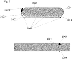
- FIGURE 1 is an example embodiment of an electronic device 100 according to the invention.
- the electronic device 100 comprises an input device 1001 configured to be connected on a surface of the electronic device 100.
- the input device 1001 comprises an interface which is configured to control the electronic device 100, the interface may be at least one of a mechanical interface or an electronic interface.
- the input device 1001 comprises a substantially elongated element 1002 which is according to this example embodiment attached to the back surface 1013 of the electronic device 100.
- the input device 1001 is configured to be attached to a front surface of the electronic device 100.
- the elongated element 1002 is configured to house an elastic band 1003.
- the elongated element 1002 is configured to form an elongated housing for storing at least part of the input device 1001.
- the elongated element 1002 may be made of metal.
- the elongated element 1002 may be made of plastic.
- the elastic band 1003 has one end configured to be attached to a corresponding end of the elongated element 1002.
- the elastic band 1003 may be made from an elastic material, for example rubber.
- the elastic band 1003 may be retractable to and retractable from the elongated element.
- the input device 1001 comprises an input member 1004 resiliently attached to the elongated element 1002. According to an example embodiment the input member 1004 may extend over the front surface of the device 100 until the back surface as well.
- the device 100 may comprise touch surface along the devices 100 back side and the user is able to control the device 100 also from the back by using the input member 1004.
- the elastic band 1003 has another end configured to be attached to an input member 1004.
- the elastic band 1003 may be a mechanical band with no intelligence.
- the elastic band 1003 may be configured to pass electric current and/ or data.
- the input member 1004 may be made from an elastic material, for example rubber.
- the input member 1004 may comprise a pressure sensor.
- the input member 1004 may be made from a rigid material, for example plastic.
- the elongated element 1002 is configured to house the elastic band 1003 in that the elongated element 1002 may be a hollow tube like element.
- the elongated element 1002 is configured to house the elastic band 1003 in that the elongated element 1002 may be a tunnel comprising an open side.
- the elongated element 1002 may be a collapsible tube. By flattening the collapsible tube, with a finger for example, the user may be able to control the movement of the input member 1004 on the surface of the electronic device 100. By flattening the collapsible tube, with a finger for example, the user may be able to stop the movement of the input member 1004 on the surface of the electronic device 100.
- the elongated element 1002 may be configured to extend a distance further from an edge of the electronic device 100 on which the elongated element 1002 is configured to be connected to. The distance may be configured to be suitable for providing a recess for the input member 1004.
- the input member 1004 may be housed in the recess while not in use.
- the elastic band 1003 into which the input member 1004 is configured to be attached may be configured to be pulled out from the elongated element 1002 with a finger of a user and released back to the mounting when not in use.
- the input device 1001 is resiliently extendable relative to a display 1006 that is part of the surface of the electronic device 100.
- the elongated element 1002 may extend over an edge of the electronic device 100 until it substantially reaches a display 1006 of the electronic device 100.
- there is no recess 1014 provided either in the space between the elongated element 1002 and the electronic device 100 or along the surface of the accessory cover.
- the input member 1004 is configured to be retracted into the elongated element 1002 when not in use and configured to be released from the elongated element 1002 when taken into use.
- the input member 1004 is configured to be housed in the elongated element 1002 is such a way that the input member 1004 is visible and configured to be grabbed by a finger of the user when taken into use.
- the electronic device 100 may comprise an accessory cover 1010.
- the accessory cover 1010 is configured to house the input device 1001.
- the input member 1004 may be housed in the recess 1014 while not in use.
- FIGURE 2 is an example embodiment of an electronic device 100 according to the invention.
- a user may control the electronic device 100 by using the input member 1004.
- the input device 1001 is provided on an edge of the electronic device 100.
- the user may be able to change the place of the input device 1001 along the edges of the electronic device 100.
- the user may hold the electronic device 100 on one hand and use the input member 1004 on the surface of the electronic device 100.
- FIGURE 3 is an example embodiment of an electronic device 100 according to the invention.
- the input member 1004 is provided on the surface of the electronic device 100 and a user may control the electronic device 100.
- an image 1011 is provided at one of the corners of the display 1006.
- the image 1011 is a track pad area.
- the element 1011 is provided as a specific area shown on the surface of the display 1006 along which the input member 1004 may be able to control information shown on the display 1006.
- an image 1012 is provided substantially next of the image 1011.
- the image 1012 is a sensitivity bar.
- the image 1012 is provided on the display 1006 as a specific area along which the user may be able to control the amount of movement which the input member 1004 on the element 1011 has according to a current use case.
- the user may be doing a task with her/ his electronic device 100 which requires only a relatively small movement of the input member 1004 for example coloring a detail in a drawing.
- the user may adjust the movement of the input member 1004 to the smallest possible along the sensitivity bar 1012.
- the user may be doing a task with her/ his electronic device 100 which requires a relatively large movement of the input member 1004, for example drawing a line extending the full length of the display 1006 of the electronic device 100.
- the user may adjust the movement of the input member 1004 to the largest possible along the sensitivity bar 1012.
- the user is able to adjust both the absolute movement of the input member 1004 and a relative movement of the input member 1004 by touching the sensitivity bar 1012 on the display 1006 of the electronic device 100.
- the user is able to adjust both the absolute movement of the input member 1004 and a relative movement of the input member 1004 by hovering over the sensitivity bar 1012.
- the user is able to adjust both the absolute movement of the input member 1004 and a relative movement of the input member 1004 by sliding her/ his finger over the sensitivity bar 1012 on the display 1006 to preferred direction.
- the sensitivity bar 1012 is one example of the physical form the image of the sensitivity bar 1012 may have, and other suitable physical forms are possible as well.
- the absolute movement referres to the actual movement of the input member on the display 1006 in that for example the user is drawing a line by using the input device 1001, over the full length of the display 1006. User may therefore move the input device 1001 over the full length of the display 1006.
- the relative movement referres to the amount of movement of the input member 1004 on the display 1006 in that for example the user is drawing a line by using the input device 1001, and the line should follow the full length of the display 1006. User may therefor move the input device 1001 only over a part of the full length of the display 1006.
- FIGURE 4 is an example embodiment of an electronic device 100 according to the invention.
- the electronic device 100 comprises a PWB 1005 configured to support different components of the electronic device 100.
- the electronic device 100 comprises a display 1006 configured to show information to a user of the electronic device 100.
- a display 1006 may provide an output, in input and/or at least part of a user interface.
- the display 1006 may be configured to show information about functionality of the electronic device 100 to a user.
- the display 1006 may be configured to show an application running in the electronic device 100.
- the display 1006 may be for example but not limited to a touch display with resistive or capcitive or inductive features or an electronic ink display or a liquid crystal display LCD.
- the electronic device 100 comprises input 1007 configured to provide a user of the electronic device 100 a means of inputting characters and/ or numbers into the electronic device 100.
- the input 1007 may be for example but not limited to a mechanical key or mechanical keys, a joystick, a navigation key, a scroll key or a touch display element.
- the input 1007 may be capacitive input, an inductive input, a resistive input.
- the electronic device 100 comprises a power source 1008 configured to provide power to the electronic device 100.
- the power source 1008 may be for example but not limited to a solar cell battery or a li-ion battery.
- the electronic device 100 comprises a transceiver 1009.
- the transceiver of an electronic device 100 may comprise for example an antenna/ transmitter/ receiver 1009, configured to provide connection to a network.
- the transceiver may transmit and receive e.g. radio frequency (RF) signals to/from external network and/or device.
- the network may comprise code devision multiple access (CDMA), wideband code devision multiple access (WCDMA), 3rd generation (3G), 4th generation (4G), global system for mobile communications (GSM), wireless local area network (WLAN).
- the electronic device 100 may comprise logic/ control/ memory 1010 configured to store, organize and process information.
- the logic /control /memory block 1010 may at least partly control internal data, operations and/or functions of the electronic device 100.
- a processor 1011 is configured to process information.
- the processor 1011 may execute instructions and enable operation of the electronic device 100.
- a speaker 1012 is configured to convert audio signals into sound
- a microphone 1015 is configured to receive for example pressure waves of a sound, and convert the pressure waves into electrical signals.
- the electronic device 100 may be at least one of the following; a mobile/ cellular phone, a lap top computer, an internet tablet, a MP3/ music player, a gaming device, a personal digital assistant.
- one of the advantages of an example embodiment may be to provide a pocket-sized accessory input device for an electronic device.
- one of the advantages may be to provide a convenient sized accessoryinput device which doesn't block the display of the electronic device.
- one of the advantages may be to provide an accessory input device which is configured to be removably connected to an electronic device.
- one of the advantages may be to provide an accessory input device which may be connected to an electronic device of which surface is inclined.
- one of the advantages may be to provide an accessory input device of which input member can be retracted away from the display of the electronic device, when the input member is not in use.
- one of the advantages may be to provide an accessory input device which is light weight. According to another example embodiment, one of the advantages may be to provide an accessory input device which is easy to use with one finger while holding the electronic device in both hands. According to another example embodiment, one of the advantages may be to provide an accessory input device which is easy to use with one finger while holding the electronic device in one hand. According to another example embodiment, one of the advantages may be to provide an accessory input device which is easy to use while the electronic device is on a flat surface. According to another example embodiment, one of the advantages may be to provide an accessory input device which is configured to be attached to an user engageable cover and the cover is affixed to the surface of the electronic device. The user engageable cover may provide a convenient way to control the electronic device.
- the user engageable cover may provide protection for the electronic device.
- one of the advantages may be to provide an accessory input device which comprises anadditional input member which is configured to be connected to the electronic device.
- one of the advantages may be to provide an accessory input device of which input member is cabable of reaching each corner of the display of the electronic device.
- one of the advantages may be to provide an accessory input device which comprises anadditional input member which is configured to be connected to the electronic device along the surface of the electronic device and the user is cabable of choosing most convenient place along the surface of the electronic device.
- one of the advantages may be to provide an accessory input device which improves gaming experience while the user is playing games with his/ her electronic device.
- the gaming experience may be improved especially in games in which a game figure is configured to be controlled by the user.
- one of the advantages may be to provide an accessory input device which improves writing experience when the user is writing text and/ or message.
- one of the advantages may be to provide an accessory input device which improves zooming experience when the user is zooming on a location of a map application.
- one of the advantages may be to provide an accessory input device which improves selection experience when the user is browsing the internet and chooses a web page of his/ her interest.
- one of the advantages may be to provide an accessory input device which improves drawing experience when the user is drawing an image on the surface of the electronic device.
- one of the advantages may be to provide an accessory input device which may be used when the electronic device is in a portrait position and when the electronice device is a landscape position.
Landscapes
- Engineering & Computer Science (AREA)
- General Engineering & Computer Science (AREA)
- Theoretical Computer Science (AREA)
- Human Computer Interaction (AREA)
- Physics & Mathematics (AREA)
- General Physics & Mathematics (AREA)
- User Interface Of Digital Computer (AREA)
- Position Input By Displaying (AREA)
Claims (13)
- Dispositif d'entrée accessoire configuré pour être relié de façon amovible à un dispositif électronique, le dispositif d'entrée comprenant
un élément d'entrée comprenant une interface configurée pour contrôler le dispositif électronique, le dispositif électronique comprenant une surface,
dans lequel l'interface est configurée pour contrôler le dispositif électronique en réponse à un déplacement de l'élément d'entrée à travers la surface du dispositif électronique destiné à contrôler le dispositif électronique, le dispositif d'entrée accessoire comprenant en outre
un élément allongé destiné à stocker l'élément d'entrée, et
dans lequel l'élément d'entrée est attaché de façon élastique à l'élément allongé, et l'élément d'entrée est configuré pour être déplacé à travers la surface avec un doigt d'un utilisateur. - Dispositif d'entrée accessoire selon la revendication 1, dans lequel l'interface en est au moins une des suivantes : une interface mécanique ou une interface électronique.
- Dispositif d'entrée accessoire selon la revendication 1 ou 2, le dispositif d'entrée accessoire étant extensible de façon élastique par rapport à un écran qui fait partie de la surface du dispositif électronique.
- Dispositif d'entrée accessoire selon l'une quelconque des revendications 1 à 3, dans lequel l'élément d'entrée est configuré pour être retiré de l'élément allongé avec un doigt d'un utilisateur.
- Dispositif d'entrée accessoire selon l'une quelconque des revendications 1 à 4, dans lequel l'élément d'entrée est configuré pour fournir une entrée pour le dispositif électronique quand l'élément d'entrée est étendu depuis l'élément allongé sur la surface du dispositif électronique.
- Dispositif d'entrée accessoire selon la revendication 3 dans lequel l'élément d'entrée est configuré pour fournir une entrée pour le dispositif électronique quand l'élément d'entrée est étendu depuis l'élément allongé sur l'écran.
- Dispositif d'entrée accessoire selon l'une quelconque des revendications 1 à 6, dans lequel l'élément d'entrée est configuré pour interagir avec le dispositif électronique en utilisant au moins un des éléments suivants : une entrée capacitive, une entrée inductive, une entrée résistive.
- Dispositif d'entrée accessoire selon l'une quelconque des revendications 1 à 6, le dispositif d'entrée accessoire étant configuré pour interagir avec le dispositif électronique en utilisant au moins un des éléments suivants : une entrée capacitive, une entrée inductive, une entrée résistive.
- Dispositif d'entrée accessoire selon l'une quelconque des revendications 1 à 8 dans lequel l' élément allongé comprend indifféremment un tube en plastique, un tube métallique ou un tube en caoutchouc.
- Housse engageable par un utilisateur comprenant le dispositif d'entrée accessoire selon l'une quelconque des revendications précédentes.
- Housse engageable par un utilisateur comprenant le dispositif d'entrée accessoire selon l'une quelconque des revendications 1 à 9, la housse étant fixée à la surface du dispositif électronique.
- Dispositif électronique portable comprenant le dispositif d'entrée accessoire selon l'une quelconque des revendications 1 à 9.
- Dispositif électronique portable comprenant la housse engageable par un utilisateur selon l'une quelconque des revendications 10 à 11.
Priority Applications (2)
| Application Number | Priority Date | Filing Date | Title |
|---|---|---|---|
| EP12189187.3A EP2722732B1 (fr) | 2012-10-19 | 2012-10-19 | Accessoire pour dispositif électronique |
| US14/057,711 US9766729B2 (en) | 2012-10-19 | 2013-10-18 | Accessory for an electronic device |
Applications Claiming Priority (1)
| Application Number | Priority Date | Filing Date | Title |
|---|---|---|---|
| EP12189187.3A EP2722732B1 (fr) | 2012-10-19 | 2012-10-19 | Accessoire pour dispositif électronique |
Publications (2)
| Publication Number | Publication Date |
|---|---|
| EP2722732A1 EP2722732A1 (fr) | 2014-04-23 |
| EP2722732B1 true EP2722732B1 (fr) | 2018-02-21 |
Family
ID=47357902
Family Applications (1)
| Application Number | Title | Priority Date | Filing Date |
|---|---|---|---|
| EP12189187.3A Not-in-force EP2722732B1 (fr) | 2012-10-19 | 2012-10-19 | Accessoire pour dispositif électronique |
Country Status (2)
| Country | Link |
|---|---|
| US (1) | US9766729B2 (fr) |
| EP (1) | EP2722732B1 (fr) |
Family Cites Families (10)
| Publication number | Priority date | Publication date | Assignee | Title |
|---|---|---|---|---|
| US5756941A (en) * | 1995-08-04 | 1998-05-26 | Pacesetter, Inc. | Retractable pen tether for a digitizer pen and method of attaching a digitizer pen to a digitizer |
| JP3636851B2 (ja) * | 1996-11-29 | 2005-04-06 | 株式会社ニデック | 灌流吸引装置 |
| US7050041B1 (en) * | 2000-10-30 | 2006-05-23 | Hewlett-Packard Development Company, L.P. | Pointing device with a cable storage winding mechanism |
| JP4619070B2 (ja) * | 2004-09-09 | 2011-01-26 | 任天堂株式会社 | ポインティング部材を備えたストラップ |
| JP4394026B2 (ja) * | 2005-04-05 | 2010-01-06 | 株式会社セガ トイズ | 電子装置 |
| US20070216664A1 (en) * | 2006-03-16 | 2007-09-20 | Marye Eric H | Stylus to assist data entry |
| CA2652424C (fr) * | 2006-05-18 | 2016-01-05 | Smart Medical Systems Ltd. | Systeme et fonctionnalite d'endoscope souple |
| US7900759B2 (en) * | 2006-08-30 | 2011-03-08 | Microsoft Corporation | Cord retraction mechanism |
| US20080150378A1 (en) * | 2006-11-07 | 2008-06-26 | Potenco, Inc. | Human power generation using a pulley |
| CN101373410B (zh) * | 2007-08-20 | 2011-03-23 | 深圳富泰宏精密工业有限公司 | 手写笔及带有该手写笔的便携式电子装置 |
-
2012
- 2012-10-19 EP EP12189187.3A patent/EP2722732B1/fr not_active Not-in-force
-
2013
- 2013-10-18 US US14/057,711 patent/US9766729B2/en active Active
Non-Patent Citations (1)
| Title |
|---|
| None * |
Also Published As
| Publication number | Publication date |
|---|---|
| US20140176461A1 (en) | 2014-06-26 |
| EP2722732A1 (fr) | 2014-04-23 |
| US9766729B2 (en) | 2017-09-19 |
Similar Documents
| Publication | Publication Date | Title |
|---|---|---|
| US20170220200A1 (en) | Extending the Functionality of a Mobile Device | |
| US9024877B2 (en) | Method for automatically switching user interface of handheld terminal device, and handheld terminal device | |
| US9007753B2 (en) | Cover for a portable electronic device | |
| KR101992192B1 (ko) | 이동 단말기 | |
| US9213428B2 (en) | Portable electronic device including flexible display | |
| CA2756821C (fr) | Dispositif electronique portable comprenant un ecran flexible | |
| US9383836B2 (en) | Stylus keyboard | |
| US20170045996A1 (en) | Mobile terminal and control method therefor | |
| KR20150025385A (ko) | 이동 단말기 및 이의 제어 방법 | |
| KR101718026B1 (ko) | 사용자 인터페이스 제공 방법 및 이를 이용하는 이동 단말기 | |
| KR101502002B1 (ko) | 근접 터치를 이용한 이동 단말기 및 그의 화면표시제어방법 | |
| KR20100094754A (ko) | 문자 입력을 위한 유저 인터페이스 방법과 이를 이용한 이동 단말기 | |
| CN103718150A (zh) | 具有基于姿势的任务管理的电子设备 | |
| KR20170059815A (ko) | 롤러블 이동 단말기 | |
| KR102101334B1 (ko) | 멀티 레벨 드라이버를 구비한 입력 장치 및 이를 포함하는 사용자 기기 | |
| US20130300673A1 (en) | Handheld device and unlocking method thereof | |
| EP2726965A1 (fr) | Appareil tactile à surfaces multiples et procédé associé | |
| EP2722732B1 (fr) | Accessoire pour dispositif électronique | |
| CA2813848C (fr) | Couvercle pour dispositif electronique portatif | |
| US20140340314A1 (en) | Portable input device | |
| JPH08123760A (ja) | 携帯型電子機器 | |
| US20140340826A1 (en) | Convenient portable input device | |
| US8319730B2 (en) | Peripheral pointing devices and methods for manufacturing the same | |
| KR20160126656A (ko) | 전자 장치의 입력 장치 | |
| KR101801143B1 (ko) | 휴대 단말기 및 그 동작 제어방법 |
Legal Events
| Date | Code | Title | Description |
|---|---|---|---|
| PUAI | Public reference made under article 153(3) epc to a published international application that has entered the european phase |
Free format text: ORIGINAL CODE: 0009012 |
|
| AK | Designated contracting states |
Kind code of ref document: A1 Designated state(s): AL AT BE BG CH CY CZ DE DK EE ES FI FR GB GR HR HU IE IS IT LI LT LU LV MC MK MT NL NO PL PT RO RS SE SI SK SM TR |
|
| AX | Request for extension of the european patent |
Extension state: BA ME |
|
| RAP1 | Party data changed (applicant data changed or rights of an application transferred) |
Owner name: NOKIA CORPORATION |
|
| 17P | Request for examination filed |
Effective date: 20140808 |
|
| RBV | Designated contracting states (corrected) |
Designated state(s): AL AT BE BG CH CY CZ DE DK EE ES FI FR GB GR HR HU IE IS IT LI LT LU LV MC MK MT NL NO PL PT RO RS SE SI SK SM TR |
|
| RAP1 | Party data changed (applicant data changed or rights of an application transferred) |
Owner name: NOKIA TECHNOLOGIES OY |
|
| GRAP | Despatch of communication of intention to grant a patent |
Free format text: ORIGINAL CODE: EPIDOSNIGR1 |
|
| INTG | Intention to grant announced |
Effective date: 20170907 |
|
| GRAS | Grant fee paid |
Free format text: ORIGINAL CODE: EPIDOSNIGR3 |
|
| GRAJ | Information related to disapproval of communication of intention to grant by the applicant or resumption of examination proceedings by the epo deleted |
Free format text: ORIGINAL CODE: EPIDOSDIGR1 |
|
| GRAL | Information related to payment of fee for publishing/printing deleted |
Free format text: ORIGINAL CODE: EPIDOSDIGR3 |
|
| INTC | Intention to grant announced (deleted) | ||
| GRAR | Information related to intention to grant a patent recorded |
Free format text: ORIGINAL CODE: EPIDOSNIGR71 |
|
| GRAA | (expected) grant |
Free format text: ORIGINAL CODE: 0009210 |
|
| INTG | Intention to grant announced |
Effective date: 20180111 |
|
| AK | Designated contracting states |
Kind code of ref document: B1 Designated state(s): AL AT BE BG CH CY CZ DE DK EE ES FI FR GB GR HR HU IE IS IT LI LT LU LV MC MK MT NL NO PL PT RO RS SE SI SK SM TR |
|
| REG | Reference to a national code |
Ref country code: GB Ref legal event code: FG4D |
|
| REG | Reference to a national code |
Ref country code: CH Ref legal event code: EP |
|
| REG | Reference to a national code |
Ref country code: AT Ref legal event code: REF Ref document number: 972421 Country of ref document: AT Kind code of ref document: T Effective date: 20180315 |
|
| REG | Reference to a national code |
Ref country code: IE Ref legal event code: FG4D |
|
| REG | Reference to a national code |
Ref country code: DE Ref legal event code: R096 Ref document number: 602012042979 Country of ref document: DE |
|
| REG | Reference to a national code |
Ref country code: NL Ref legal event code: MP Effective date: 20180221 |
|
| REG | Reference to a national code |
Ref country code: LT Ref legal event code: MG4D |
|
| REG | Reference to a national code |
Ref country code: AT Ref legal event code: MK05 Ref document number: 972421 Country of ref document: AT Kind code of ref document: T Effective date: 20180221 |
|
| PG25 | Lapsed in a contracting state [announced via postgrant information from national office to epo] |
Ref country code: FI Free format text: LAPSE BECAUSE OF FAILURE TO SUBMIT A TRANSLATION OF THE DESCRIPTION OR TO PAY THE FEE WITHIN THE PRESCRIBED TIME-LIMIT Effective date: 20180221 Ref country code: HR Free format text: LAPSE BECAUSE OF FAILURE TO SUBMIT A TRANSLATION OF THE DESCRIPTION OR TO PAY THE FEE WITHIN THE PRESCRIBED TIME-LIMIT Effective date: 20180221 Ref country code: CY Free format text: LAPSE BECAUSE OF FAILURE TO SUBMIT A TRANSLATION OF THE DESCRIPTION OR TO PAY THE FEE WITHIN THE PRESCRIBED TIME-LIMIT Effective date: 20180221 Ref country code: LT Free format text: LAPSE BECAUSE OF FAILURE TO SUBMIT A TRANSLATION OF THE DESCRIPTION OR TO PAY THE FEE WITHIN THE PRESCRIBED TIME-LIMIT Effective date: 20180221 Ref country code: NL Free format text: LAPSE BECAUSE OF FAILURE TO SUBMIT A TRANSLATION OF THE DESCRIPTION OR TO PAY THE FEE WITHIN THE PRESCRIBED TIME-LIMIT Effective date: 20180221 Ref country code: NO Free format text: LAPSE BECAUSE OF FAILURE TO SUBMIT A TRANSLATION OF THE DESCRIPTION OR TO PAY THE FEE WITHIN THE PRESCRIBED TIME-LIMIT Effective date: 20180521 Ref country code: ES Free format text: LAPSE BECAUSE OF FAILURE TO SUBMIT A TRANSLATION OF THE DESCRIPTION OR TO PAY THE FEE WITHIN THE PRESCRIBED TIME-LIMIT Effective date: 20180221 |
|
| PG25 | Lapsed in a contracting state [announced via postgrant information from national office to epo] |
Ref country code: RS Free format text: LAPSE BECAUSE OF FAILURE TO SUBMIT A TRANSLATION OF THE DESCRIPTION OR TO PAY THE FEE WITHIN THE PRESCRIBED TIME-LIMIT Effective date: 20180221 Ref country code: BG Free format text: LAPSE BECAUSE OF FAILURE TO SUBMIT A TRANSLATION OF THE DESCRIPTION OR TO PAY THE FEE WITHIN THE PRESCRIBED TIME-LIMIT Effective date: 20180521 Ref country code: AT Free format text: LAPSE BECAUSE OF FAILURE TO SUBMIT A TRANSLATION OF THE DESCRIPTION OR TO PAY THE FEE WITHIN THE PRESCRIBED TIME-LIMIT Effective date: 20180221 Ref country code: LV Free format text: LAPSE BECAUSE OF FAILURE TO SUBMIT A TRANSLATION OF THE DESCRIPTION OR TO PAY THE FEE WITHIN THE PRESCRIBED TIME-LIMIT Effective date: 20180221 Ref country code: SE Free format text: LAPSE BECAUSE OF FAILURE TO SUBMIT A TRANSLATION OF THE DESCRIPTION OR TO PAY THE FEE WITHIN THE PRESCRIBED TIME-LIMIT Effective date: 20180221 Ref country code: GR Free format text: LAPSE BECAUSE OF FAILURE TO SUBMIT A TRANSLATION OF THE DESCRIPTION OR TO PAY THE FEE WITHIN THE PRESCRIBED TIME-LIMIT Effective date: 20180522 |
|
| PG25 | Lapsed in a contracting state [announced via postgrant information from national office to epo] |
Ref country code: PL Free format text: LAPSE BECAUSE OF FAILURE TO SUBMIT A TRANSLATION OF THE DESCRIPTION OR TO PAY THE FEE WITHIN THE PRESCRIBED TIME-LIMIT Effective date: 20180221 Ref country code: IT Free format text: LAPSE BECAUSE OF FAILURE TO SUBMIT A TRANSLATION OF THE DESCRIPTION OR TO PAY THE FEE WITHIN THE PRESCRIBED TIME-LIMIT Effective date: 20180221 Ref country code: EE Free format text: LAPSE BECAUSE OF FAILURE TO SUBMIT A TRANSLATION OF THE DESCRIPTION OR TO PAY THE FEE WITHIN THE PRESCRIBED TIME-LIMIT Effective date: 20180221 Ref country code: RO Free format text: LAPSE BECAUSE OF FAILURE TO SUBMIT A TRANSLATION OF THE DESCRIPTION OR TO PAY THE FEE WITHIN THE PRESCRIBED TIME-LIMIT Effective date: 20180221 Ref country code: AL Free format text: LAPSE BECAUSE OF FAILURE TO SUBMIT A TRANSLATION OF THE DESCRIPTION OR TO PAY THE FEE WITHIN THE PRESCRIBED TIME-LIMIT Effective date: 20180221 |
|
| REG | Reference to a national code |
Ref country code: DE Ref legal event code: R097 Ref document number: 602012042979 Country of ref document: DE |
|
| PG25 | Lapsed in a contracting state [announced via postgrant information from national office to epo] |
Ref country code: DK Free format text: LAPSE BECAUSE OF FAILURE TO SUBMIT A TRANSLATION OF THE DESCRIPTION OR TO PAY THE FEE WITHIN THE PRESCRIBED TIME-LIMIT Effective date: 20180221 Ref country code: SK Free format text: LAPSE BECAUSE OF FAILURE TO SUBMIT A TRANSLATION OF THE DESCRIPTION OR TO PAY THE FEE WITHIN THE PRESCRIBED TIME-LIMIT Effective date: 20180221 Ref country code: SM Free format text: LAPSE BECAUSE OF FAILURE TO SUBMIT A TRANSLATION OF THE DESCRIPTION OR TO PAY THE FEE WITHIN THE PRESCRIBED TIME-LIMIT Effective date: 20180221 Ref country code: CZ Free format text: LAPSE BECAUSE OF FAILURE TO SUBMIT A TRANSLATION OF THE DESCRIPTION OR TO PAY THE FEE WITHIN THE PRESCRIBED TIME-LIMIT Effective date: 20180221 |
|
| PLBE | No opposition filed within time limit |
Free format text: ORIGINAL CODE: 0009261 |
|
| STAA | Information on the status of an ep patent application or granted ep patent |
Free format text: STATUS: NO OPPOSITION FILED WITHIN TIME LIMIT |
|
| 26N | No opposition filed |
Effective date: 20181122 |
|
| PG25 | Lapsed in a contracting state [announced via postgrant information from national office to epo] |
Ref country code: SI Free format text: LAPSE BECAUSE OF FAILURE TO SUBMIT A TRANSLATION OF THE DESCRIPTION OR TO PAY THE FEE WITHIN THE PRESCRIBED TIME-LIMIT Effective date: 20180221 |
|
| REG | Reference to a national code |
Ref country code: DE Ref legal event code: R119 Ref document number: 602012042979 Country of ref document: DE |
|
| REG | Reference to a national code |
Ref country code: CH Ref legal event code: PL |
|
| GBPC | Gb: european patent ceased through non-payment of renewal fee |
Effective date: 20181019 |
|
| REG | Reference to a national code |
Ref country code: BE Ref legal event code: MM Effective date: 20181031 |
|
| PG25 | Lapsed in a contracting state [announced via postgrant information from national office to epo] |
Ref country code: MC Free format text: LAPSE BECAUSE OF FAILURE TO SUBMIT A TRANSLATION OF THE DESCRIPTION OR TO PAY THE FEE WITHIN THE PRESCRIBED TIME-LIMIT Effective date: 20180221 Ref country code: LU Free format text: LAPSE BECAUSE OF NON-PAYMENT OF DUE FEES Effective date: 20181019 |
|
| REG | Reference to a national code |
Ref country code: IE Ref legal event code: MM4A |
|
| PG25 | Lapsed in a contracting state [announced via postgrant information from national office to epo] |
Ref country code: DE Free format text: LAPSE BECAUSE OF NON-PAYMENT OF DUE FEES Effective date: 20190501 |
|
| PG25 | Lapsed in a contracting state [announced via postgrant information from national office to epo] |
Ref country code: BE Free format text: LAPSE BECAUSE OF NON-PAYMENT OF DUE FEES Effective date: 20181031 Ref country code: CH Free format text: LAPSE BECAUSE OF NON-PAYMENT OF DUE FEES Effective date: 20181031 Ref country code: LI Free format text: LAPSE BECAUSE OF NON-PAYMENT OF DUE FEES Effective date: 20181031 Ref country code: FR Free format text: LAPSE BECAUSE OF NON-PAYMENT OF DUE FEES Effective date: 20181031 |
|
| PG25 | Lapsed in a contracting state [announced via postgrant information from national office to epo] |
Ref country code: IE Free format text: LAPSE BECAUSE OF NON-PAYMENT OF DUE FEES Effective date: 20181019 Ref country code: GB Free format text: LAPSE BECAUSE OF NON-PAYMENT OF DUE FEES Effective date: 20181019 |
|
| PG25 | Lapsed in a contracting state [announced via postgrant information from national office to epo] |
Ref country code: MT Free format text: LAPSE BECAUSE OF NON-PAYMENT OF DUE FEES Effective date: 20181019 |
|
| PG25 | Lapsed in a contracting state [announced via postgrant information from national office to epo] |
Ref country code: TR Free format text: LAPSE BECAUSE OF FAILURE TO SUBMIT A TRANSLATION OF THE DESCRIPTION OR TO PAY THE FEE WITHIN THE PRESCRIBED TIME-LIMIT Effective date: 20180221 |
|
| PG25 | Lapsed in a contracting state [announced via postgrant information from national office to epo] |
Ref country code: PT Free format text: LAPSE BECAUSE OF FAILURE TO SUBMIT A TRANSLATION OF THE DESCRIPTION OR TO PAY THE FEE WITHIN THE PRESCRIBED TIME-LIMIT Effective date: 20180221 |
|
| PG25 | Lapsed in a contracting state [announced via postgrant information from national office to epo] |
Ref country code: HU Free format text: LAPSE BECAUSE OF FAILURE TO SUBMIT A TRANSLATION OF THE DESCRIPTION OR TO PAY THE FEE WITHIN THE PRESCRIBED TIME-LIMIT; INVALID AB INITIO Effective date: 20121019 Ref country code: MK Free format text: LAPSE BECAUSE OF NON-PAYMENT OF DUE FEES Effective date: 20180221 |
|
| PG25 | Lapsed in a contracting state [announced via postgrant information from national office to epo] |
Ref country code: IS Free format text: LAPSE BECAUSE OF FAILURE TO SUBMIT A TRANSLATION OF THE DESCRIPTION OR TO PAY THE FEE WITHIN THE PRESCRIBED TIME-LIMIT Effective date: 20180621 |