EP2722227B1 - Motor vehicle light installation and corresponding operating method - Google Patents
Motor vehicle light installation and corresponding operating method Download PDFInfo
- Publication number
- EP2722227B1 EP2722227B1 EP13002960.6A EP13002960A EP2722227B1 EP 2722227 B1 EP2722227 B1 EP 2722227B1 EP 13002960 A EP13002960 A EP 13002960A EP 2722227 B1 EP2722227 B1 EP 2722227B1
- Authority
- EP
- European Patent Office
- Prior art keywords
- vehicle
- flashing
- luminaire
- headlight
- motor vehicle
- Prior art date
- Legal status (The legal status is an assumption and is not a legal conclusion. Google has not performed a legal analysis and makes no representation as to the accuracy of the status listed.)
- Active
Links
Images


Classifications
-
- B—PERFORMING OPERATIONS; TRANSPORTING
- B60—VEHICLES IN GENERAL
- B60Q—ARRANGEMENT OF SIGNALLING OR LIGHTING DEVICES, THE MOUNTING OR SUPPORTING THEREOF OR CIRCUITS THEREFOR, FOR VEHICLES IN GENERAL
- B60Q1/00—Arrangement of optical signalling or lighting devices, the mounting or supporting thereof or circuits therefor
- B60Q1/02—Arrangement of optical signalling or lighting devices, the mounting or supporting thereof or circuits therefor the devices being primarily intended to illuminate the way ahead or to illuminate other areas of way or environments
- B60Q1/04—Arrangement of optical signalling or lighting devices, the mounting or supporting thereof or circuits therefor the devices being primarily intended to illuminate the way ahead or to illuminate other areas of way or environments the devices being headlights
- B60Q1/14—Arrangement of optical signalling or lighting devices, the mounting or supporting thereof or circuits therefor the devices being primarily intended to illuminate the way ahead or to illuminate other areas of way or environments the devices being headlights having dimming means
- B60Q1/1415—Dimming circuits
- B60Q1/1423—Automatic dimming circuits, i.e. switching between high beam and low beam due to change of ambient light or light level in road traffic
-
- B—PERFORMING OPERATIONS; TRANSPORTING
- B60—VEHICLES IN GENERAL
- B60Q—ARRANGEMENT OF SIGNALLING OR LIGHTING DEVICES, THE MOUNTING OR SUPPORTING THEREOF OR CIRCUITS THEREFOR, FOR VEHICLES IN GENERAL
- B60Q1/00—Arrangement of optical signalling or lighting devices, the mounting or supporting thereof or circuits therefor
- B60Q1/02—Arrangement of optical signalling or lighting devices, the mounting or supporting thereof or circuits therefor the devices being primarily intended to illuminate the way ahead or to illuminate other areas of way or environments
- B60Q1/04—Arrangement of optical signalling or lighting devices, the mounting or supporting thereof or circuits therefor the devices being primarily intended to illuminate the way ahead or to illuminate other areas of way or environments the devices being headlights
- B60Q1/18—Arrangement of optical signalling or lighting devices, the mounting or supporting thereof or circuits therefor the devices being primarily intended to illuminate the way ahead or to illuminate other areas of way or environments the devices being headlights being additional front lights
-
- B—PERFORMING OPERATIONS; TRANSPORTING
- B60—VEHICLES IN GENERAL
- B60Q—ARRANGEMENT OF SIGNALLING OR LIGHTING DEVICES, THE MOUNTING OR SUPPORTING THEREOF OR CIRCUITS THEREFOR, FOR VEHICLES IN GENERAL
- B60Q1/00—Arrangement of optical signalling or lighting devices, the mounting or supporting thereof or circuits therefor
- B60Q1/26—Arrangement of optical signalling or lighting devices, the mounting or supporting thereof or circuits therefor the devices being primarily intended to indicate the vehicle, or parts thereof, or to give signals, to other traffic
- B60Q1/28—Arrangement of optical signalling or lighting devices, the mounting or supporting thereof or circuits therefor the devices being primarily intended to indicate the vehicle, or parts thereof, or to give signals, to other traffic for indicating front of vehicle
-
- B—PERFORMING OPERATIONS; TRANSPORTING
- B60—VEHICLES IN GENERAL
- B60Q—ARRANGEMENT OF SIGNALLING OR LIGHTING DEVICES, THE MOUNTING OR SUPPORTING THEREOF OR CIRCUITS THEREFOR, FOR VEHICLES IN GENERAL
- B60Q1/00—Arrangement of optical signalling or lighting devices, the mounting or supporting thereof or circuits therefor
- B60Q1/26—Arrangement of optical signalling or lighting devices, the mounting or supporting thereof or circuits therefor the devices being primarily intended to indicate the vehicle, or parts thereof, or to give signals, to other traffic
- B60Q1/34—Arrangement of optical signalling or lighting devices, the mounting or supporting thereof or circuits therefor the devices being primarily intended to indicate the vehicle, or parts thereof, or to give signals, to other traffic for indicating change of drive direction
- B60Q1/38—Arrangement of optical signalling or lighting devices, the mounting or supporting thereof or circuits therefor the devices being primarily intended to indicate the vehicle, or parts thereof, or to give signals, to other traffic for indicating change of drive direction using immovably-mounted light sources, e.g. fixed flashing lamps
- B60Q1/381—Arrangement of optical signalling or lighting devices, the mounting or supporting thereof or circuits therefor the devices being primarily intended to indicate the vehicle, or parts thereof, or to give signals, to other traffic for indicating change of drive direction using immovably-mounted light sources, e.g. fixed flashing lamps with several light sources activated in sequence, e.g. to create a sweep effect
-
- B—PERFORMING OPERATIONS; TRANSPORTING
- B60—VEHICLES IN GENERAL
- B60Q—ARRANGEMENT OF SIGNALLING OR LIGHTING DEVICES, THE MOUNTING OR SUPPORTING THEREOF OR CIRCUITS THEREFOR, FOR VEHICLES IN GENERAL
- B60Q1/00—Arrangement of optical signalling or lighting devices, the mounting or supporting thereof or circuits therefor
- B60Q1/0029—Spatial arrangement
- B60Q1/0041—Spatial arrangement of several lamps in relation to each other
-
- B—PERFORMING OPERATIONS; TRANSPORTING
- B60—VEHICLES IN GENERAL
- B60Q—ARRANGEMENT OF SIGNALLING OR LIGHTING DEVICES, THE MOUNTING OR SUPPORTING THEREOF OR CIRCUITS THEREFOR, FOR VEHICLES IN GENERAL
- B60Q2300/00—Indexing codes for automatically adjustable headlamps or automatically dimmable headlamps
- B60Q2300/10—Indexing codes relating to particular vehicle conditions
- B60Q2300/14—Other vehicle conditions
- B60Q2300/142—Turn signal actuation
-
- B—PERFORMING OPERATIONS; TRANSPORTING
- B60—VEHICLES IN GENERAL
- B60Q—ARRANGEMENT OF SIGNALLING OR LIGHTING DEVICES, THE MOUNTING OR SUPPORTING THEREOF OR CIRCUITS THEREFOR, FOR VEHICLES IN GENERAL
- B60Q2400/00—Special features or arrangements of exterior signal lamps for vehicles
- B60Q2400/30—Daytime running lights [DRL], e.g. circuits or arrangements therefor
Description
Die Erfindung betrifft eine Kraftfahrzeug-Lichtanlage für ein Kraftfahrzeug, insbesondere für ein Nutzfahrzeug, wie beispielsweise einen Lastkraftwagen oder einen Omnibus. Weiterhin betrifft die Erfindung ein entsprechendes Betriebsverfahren.The invention relates to a motor vehicle lighting system for a motor vehicle, in particular for a commercial vehicle, such as a truck or a bus. Furthermore, the invention relates to a corresponding operating method.
Moderne Kraftfahrzeug-Lichtanlagen weisen oftmals zusätzlich zu Abblendlicht, Fernlicht, Nebelscheinwerfern und Blinkern ein sogenanntes Tagfahrlicht auf, das bei guten Sichtverhältnissen am Tag eingesetzt wird, um die Erkennbarkeit des Kraftfahrzeugs zu verbessern. Derartige Tagfahrleuchten werden oftmals in LED-Technik als Lichtband ausgeführt, wobei das Lichtband auch zu gestalterischen Zwecken eingesetzt werden kann. Bei einer Integration der Tagfahrleuchte zusammen mit einer Blinkleuchte in ein Scheinwerfermodul kann die Erkennbarkeit der Blinkleuchte jedoch beeinträchtigt werden, wenn die Tagfahrleuchte angeschaltet ist. Dies gilt insbesondere dann, wenn die Blinkleuchte und die Tagfahrleuchte als Lichtband in LED-Technik ausgeführt sind.Modern motor vehicle lighting systems often have in addition to low beam, high beam, fog lights and turn signals on a so-called daytime running lights, which is used in good visibility conditions during the day to improve the visibility of the motor vehicle. Such daytime running lights are often designed in LED technology as a light band, the light band can also be used for creative purposes. However, if the daytime running light is integrated with a turn signal in a headlight module, the visibility of the turn signal may be impaired when the daytime running light is turned on. This is especially true when the flashing light and the daytime running light are designed as a light strip in LED technology.
Weiterhin ist zum Stand der Technik hinzuweisen auf
Schließlich offenbart
Der Erfindung liegt deshalb die Aufgabe zugrunde, bei einer Kraftfahrzeug-Lichtanlage die Erkennbarkeit der Blinkleuchte bei eingeschaltetem Tagfahrlicht zu verbessern.The invention is therefore based on the object in a motor vehicle lighting system to improve the visibility of the flashing light when the daytime running lights.
Diese Aufgabe wird durch eine erfindungsgemäße Kraftfahrzeug-Lichtanlage bzw. durch ein entsprechendes Betriebsverfahren gemäß den nebengeordneten Ansprüchen gelöst. Die Erfindung umfasst die allgemeine technische Lehre, die Beleuchtungscharakteristik (z.B. Leuchtkraft, Leuchtfläche) der Tagfahrleuchte vorübergehend zu beeinflussen, während die Blinkleuchte eingeschaltet ist, um die Erkennbarkeit der Blinkleuchte zu verbessern.This object is achieved by a motor vehicle lighting system according to the invention or by a corresponding operating method according to the independent claims. The invention comprises the general technical teaching to temporarily influence the lighting characteristic (eg luminosity, luminous area) of the daytime running light while the flashing light is switched on in order to improve the recognizability of the flashing light.
Die erfindungsgemäße Kraftfahrzeug-Lichtanlage weist mindestens eine Blinkleuchte zur Fahrtrichtungsanzeige und/oder als Warnblinker an einer Fahrzeugfront des Kraftfahrzeugs auf. In der Regel umfasst die erfindungsgemäße Kraftfahrzeug-Lichtanlage mindestens vier Blinkleuchten, die jeweils paarweise an der Fahrzeugfront und am Fahrzeugheck jeweils auf der linken bzw. rechten Seite des Kraftfahrzeugs angeordnet sind. Die Erfindung beansprucht jedoch auch Schutz für eine Komponente einer derartigen Kraftfahrzeug-Lichtanlage mit nur einer einzigen Blinkleuchte, die erfindungsgemäß angesteuert wird.The motor vehicle lighting system according to the invention has at least one flashing light for indicating the direction of travel and / or as hazard warning lights on a vehicle front of the motor vehicle. In general, the motor vehicle lighting system according to the invention comprises at least four flashing lights, which are each arranged in pairs on the vehicle front and the rear of the vehicle respectively on the left or right side of the motor vehicle. However, the invention also claims protection for a component of such a motor vehicle lighting system with only a single flashing light, which is controlled according to the invention.
Darüber hinaus umfasst die erfindungsgemäße Kraftfahrzeug-Lichtanlage mindestens einen Scheinwerfer (z.B. Tagfahrleuchte) zur Lichtabgabe mit einer bestimmten Beleuchtungscharakteristik an der Fahrzeugfront des Kraftfahrzeugs, insbesondere mit einer bestimmten Leuchtkraft und einer bestimmten Leuchtfläche. Bei diesem Scheinwerfer, der erfindungsgemäß angesteuert wird, handelt es sich vorzugsweise um eine Tagfahrleuchte, jedoch kann das erfindungsgemäße Prinzip auch auf andere Typen von Scheinwerfern angewendet werden, wie beispielsweise Nebelscheinwerfer, Fernlicht oder Abblendlicht, wobei jedoch die gesetzlichen Bestimmungen hinsichtlich der Leuchtkraft der jeweiligen Scheinwerfer aus Sicherheitsgründen beachtet werden müssen.In addition, the motor vehicle lighting system according to the invention comprises at least one headlight (for example daytime running light) for emitting light with a specific lighting characteristic on the vehicle front of the motor vehicle, in particular with a specific luminosity and a specific luminous surface. In this headlamp, which is controlled according to the invention, it is preferably a daytime running light, but the principle of the invention can also be applied to other types of headlamps, such as fog lights, high beam or low beam, but the statutory provisions regarding the luminosity of the respective headlights for safety reasons.
Darüber hinaus umfasst die erfindungsgemäße Kraftfahrzeug-Lichtanlage in herkömmlicher Weise mindestens einen Schalter zum Einschalten bzw. Ausschalten der Blinkleuchte.In addition, the motor vehicle lighting system according to the invention comprises in a conventional manner at least one switch for switching on or off the flashing light.
Ferner weist die erfindungsgemäße Kraftfahrzeug-Lichtanlage eine Steuereinheit auf, die den Scheinwerfer (z.B. Tagfahrlicht) ansteuert, was an sich aus dem Stand der Technik bekannt ist.Furthermore, the motor vehicle lighting system according to the invention has a control unit which controls the headlight (for example daytime running light), which is known per se from the prior art.
Die Erfindung sieht nun zusätzlich vor, dass die Steuereinheit die Beleuchtungscharakteristik des Scheinwerfers vorübergehend beeinflusst, während die Blinkleuchte eingeschaltet ist, um die Erkennbarkeit der Blinkleuchte zu verbessern. Die Steuereinheit erfasst also vorzugsweise den Schaltzustand des Schalters zum Einschalten bzw. Ausschalten der Blinkleuchte und schaltet dann die jeweilige Blinkleuchte an bzw. aus. Darüber hinaus beeinflusst die Steuereinheit dann im eingeschalteten Zustand der Blinkleuchte die Beleuchtungscharakteristik des benachbarten Scheinwerfers so, dass die Erkennbarkeit der Blinkleuchte verbessert wird.The invention now additionally provides that the control unit temporarily influences the lighting characteristic of the headlamp while the flashing light is switched on in order to improve the recognizability of the flashing light. The control unit thus preferably detects the switching state of the switch for switching on and switching off the flashing light and then switches the respective flashing light on or off. In addition, the control unit then influences the lighting characteristic of the adjacent headlamp in the on state of the turn signal, so that the visibility of the turn signal is improved.
Gemäß der Erfindung wird die Beleuchtungscharakteristik des Scheinwerfers (z.B. Tagfahrleuchte) im eingeschalteten Zustand der Blinkleuchte dadurch beeinflusst, dass die Leuchtkraft des Scheinwerfers (z.B. Tagfahrleuchte) verringert wird. Bei einem Einschalten einer Blinkleuchte wird die benachbarte Tagfahrleuchte also quasi herunter gedimmt, damit die Blinkleuchte besser erkennbar ist.According to the invention, the lighting characteristic of the headlamp (eg daytime running light) in the on state of the turn signal is influenced by the fact that the luminosity of the headlamp (eg daytime running light) is reduced. When turning on a turn signal, the adjacent daytime running light is thus dimmed down so that the turn signal is better visible.
Gemäß der Erfindung wird die Beleuchtungscharakteristik des Scheinwerfers im eingeschalteten Zustand der Blinkleuchte dadurch beeinflusst, dass die Leuchtfläche des benachbarten Scheinwerfers (z.B. Tagfahrlicht) räumlich verlagert wird, und zwar weg von der Blinkleuchte. Beispielsweise kann die Tagfahrleuchte eine segmentierte Leuchtfläche aufweisen, die aus mehreren einzeln ansteuerbaren Leuchtelementen besteht. Im eingeschalteten Zustand einer Blinkleuchte können dann diejenigen Leuchtsegmente des Scheinwerfers abgeschaltet werden, die in unmittelbarer Nähe der Blinkleuchte angeordnet sind, während die weiter entfernten Leuchtsegmente des Scheinwerfers angeschaltet bleiben. Zur Aufrechterhaltung einer ausreichenden Leuchtkraft des Scheinwerfers (z.B. Tagfahrleuchte) können im eingeschalteten Zustand der Blinkleuchte weitere Leuchtsegmente des Scheinwerfers zugeschaltet werden, die sich weiter entfernt von der Blinkleuchte befinden und die Erkennbarkeit der Blinkleuchte deshalb nicht beeinträchtigen.According to the invention, the lighting characteristic of the headlamp in the switched-on state of the flashing light is influenced by the fact that the luminous area of the adjacent headlamp (for example daytime running light) is spatially displaced away from the flashing light. For example, the daytime running light may have a segmented luminous surface, which consists of a plurality of individually controllable lighting elements. When switched on a flashing light then those lighting segments of the headlamp can be switched off, which are located in the immediate vicinity of the flashing light, while the more distant lighting segments of the headlight remain turned on. In order to maintain a sufficient luminosity of the headlamp (for example, daytime running light) can be switched on when the flasher is switched on more lighting segments of the headlamp, which are located further from the flashing light and therefore not affect the visibility of the flashing light.
Die beiden vorstehend genannten Varianten der Erfindung (Herabsetzung der Leuchtkraft, Verlagerung der Leuchtfläche) können im Rahmen der Erfindung auch in Kombination miteinander eingesetzt werden.The two aforementioned variants of the invention (reduction of the luminosity, shift of the luminous area) can also be used in combination with one another in the context of the invention.
Die Erfindung sieht vor, dass die Beleuchtungscharakteristik des Scheinwerfers im eingeschalteten Zustand der Blinkleuchte periodisch beeinflusst wird. Beispielsweise kann die Leuchtkraft des benachbarten Scheinwerfers (z.B. Tagfahrleuchte) im eingeschalteten Zustand der Blinkleuchte periodisch verändert werden. Die Änderungsfrequenz der Leuchtkraft des Scheinwerfers entspricht hierbei der Blinkfrequenz der Blinkleuchte. Darüber hinaus ist vorgesehen, dass die Beleuchtungscharakteristik des Scheinwerfers (z.B. Tagfahrleuchte) im Gegentakt zu der Blinkfrequenz der Blinkleuchte verändert wird. Es wurde bereits eingangs kurz erwähnt, dass die erfindungsgemäße Kraftfahrzeug-Lichtanlage vorzugsweise Blinkleuchten und Tagfahrleuchten an beiden Fahrzeugseiten aufweist, d.h. an der linken Fahrzeugseite und an der rechten Fahrzeugseite. Bei einem Einschalten einer Blinkleuchte auf einer einzigen Fahrzeugseite besteht im Rahmen der Erfindung die Möglichkeit, dass die Beleuchtungscharakteristik der Scheinwerfer (z.B. Tagfahrlicht) an beiden Fahrzeugseiten beeinflusst wird, d.h. auch an der Fahrzeugseite, an der die Blinkleuchte nicht eingeschaltet ist. Alternativ besteht die Möglichkeit, dass die Beleuchtungscharakteristik nur bei dem Scheinwerfer auf der Fahrzeugseite beeinflusst wird, an der die Blinkleuchte eingeschaltet ist. Bei einer Betätigung als Warnblinker an beiden Fahrzeugseiten wird die Beleuchtungscharakteristik der Scheinwerfer (z.B. Tagfahrleuchte) dagegen vorzugsweise an beiden Fahrzeugseiten beeinflusst, um die Erkennbarkeit der Blinkleuchte zu verbessern.The invention provides that the lighting characteristic of the headlamp is periodically influenced in the on state of the turn signal. For example, the luminosity of the adjacent headlight (eg daytime running light) can be changed periodically in the switched-on state of the flashing light. The change frequency of the luminosity of the headlamp corresponds to the flashing frequency of the flashing light. In addition, it is envisaged that the lighting characteristic of the headlamp (eg daytime running light) is changed in push-pull to the flashing frequency of the flashing light. It has already been briefly mentioned at the outset that the motor vehicle lighting system according to the invention preferably has flashing lights and daytime running lights on both sides of the vehicle has, ie on the left side of the vehicle and on the right side of the vehicle. When turning on a flashing light on a single vehicle side is within the scope of the invention, the possibility that the lighting characteristics of the headlights (eg daytime running light) is affected on both sides of the vehicle, ie also on the vehicle side, where the flashing light is not turned on. Alternatively, there is the possibility that the lighting characteristic is only affected in the headlight on the vehicle side, on which the flashing light is turned on. When actuated as a hazard warning lights on both sides of the vehicle illumination characteristic of the headlights (eg daytime running light), however, preferably influenced on both sides of the vehicle to improve the visibility of the turn signal.
Ferner ist zu erwähnen, dass es sich bei dem Scheinwerfer vorzugsweise um ein Tagfahrlicht handelt, das beispielsweise als LED-Tagfahrlicht ausgebildet ist. Es wurde jedoch bereits vorstehend darauf hingewiesen, dass sich das erfindungsgemäße Prinzip auch auf andere Scheinwerfertypen anwenden lässt, wie beispielsweise Abblendlicht, Fernlicht, Nebelscheinwerfer. Darüber hinaus ist zu erwähnen, dass das erfindungsgemäße Prinzip besonders dann vorteilhaft ist, wenn die Blinkleuchte und der Scheinwerfer (z.B. Tagfahrlicht) in einem gemeinsamen Scheinwerfermodul integriert sind, da sich die Blinkleuchte dann in unmittelbarer Nachbarschaft zu dem Scheinwerfer befindet, wodurch die Erkennbarkeit der Blinkleuchte bei eingeschaltetem Scheinwerfer beeinträchtigt werden könnte.It should also be mentioned that the headlamp is preferably a daytime running light which is embodied, for example, as an LED daytime running light. However, it has already been pointed out above that the principle according to the invention can also be applied to other types of headlamps, such as, for example, low beam, high beam, fog lights. In addition, it should be mentioned that the principle according to the invention is particularly advantageous if the flashing light and the headlight (eg daytime running light) are integrated in a common headlight module, since the flashing light is then in the immediate vicinity of the headlight, whereby the recognizability of the flashing light could be affected when the headlamp is on.
Darüber hinaus ist zu erwähnen, dass die Erfindung nicht nur Schutz beansprucht für die vorstehend beschriebene erfindungsgemäße Kraftfahrzeug-Lichtanlage. Vielmehr beansprucht die Erfindung auch Schutz für ein ganzes Kraftfahrzeug mit einer derartigen Kraftfahrzeug-Lichtanlage. Bei diesem Kraftfahrzeug kann es sich beispielsweise um ein Nutzfahrzeug handeln, wie beispielsweise einen Lastkraftwagen oder einen Omnibus.In addition, it should be mentioned that the invention not only claims protection for the motor vehicle lighting system according to the invention described above. Rather, the invention also claims protection for a whole motor vehicle with such a motor vehicle lighting system. In this motor vehicle may be, for example, a commercial vehicle, such as a truck or a bus.
Schließlich ist noch zu erwähnen, dass die Erfindung auch ein entsprechendes Betriebsverfahren für eine Kraftfahrzeug-Lichtanlage umfasst, wie sich bereits aus der vorstehenden Beschreibung ergibt, so dass auf eine weitere Beschreibung des Betriebsverfahrens verzichtet werden kann.Finally, it should also be mentioned that the invention also includes a corresponding operating method for a motor vehicle lighting system, as already apparent from the above description, so that it is possible to dispense with a further description of the operating method.
Andere vorteilhafte Weiterbildungen der Erfindung sind in den Unteransprüchen gekennzeichnet oder werden nachstehend zusammen mit der Beschreibung der bevorzugten Ausführungsbeispiele der Erfindung anhand der Figuren näher erläutert. Es zeigen:
-
Figur 1 -
Figur 2A eine Frontansicht eines nicht erfindungsgemäßen Scheinwerfermoduls an einer Frontseite eines Kraftfahrzeugs auf der rechten Seite, wobei die Blinkleuchte ausgeschaltet ist, -
Figur 2B eine Abwandlung vonFigur 2A , wobei die Blinkleuchte eingeschaltet ist, -
Figur 3A eine Abwandlung vonFigur 2A , wobei das Tagfahrlicht mehrere Leuchtsegmente aufweist, die separat schaltbar sind, -
Figur 3B das Scheinwerfermodul gemäßFigur 3A , wobei der Blinker angeschaltet ist, -
Figur 4 -
Figur 5 -
Figur 6
-
FIG. 1 a schematic representation of a motor vehicle lighting system according to the invention, -
FIG. 2A a front view of a non-inventive headlamp module on a front side of a motor vehicle on the right side, the flashing light is off, -
FIG. 2B a modification ofFIG. 2A with the flashing light on, -
FIG. 3A a modification ofFIG. 2A wherein the daytime running light has a plurality of light segments which are separately switchable, -
FIG. 3B the headlight module according toFIG. 3A with the turn signal on, -
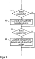
FIG. 4 a flowchart to illustrate the operating method not according to the invention, wherein the daytime running light is dimmed on both sides with turn signal, -
FIG. 5 a flowchart illustrating the operating method not according to the invention, wherein the daytime running light is dimmed only on the side at which a flashing light is turned on, and -
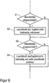
FIG. 6 a flowchart illustrating the non-inventive operating method when turning on a hazard warning lights.
Zur Vereinfachung sind hierbei nur Leuchten an der Frontseite des Kraftfahrzeugs dargestellt. Die erfindungsgemäße Kraftfahrzeug-Lichtanlage umfasst jedoch auch Leuchten am Fahrzeugheck, die jedoch im Rahmen der Erfindung nicht von Bedeutung sind und deshalb auch nicht dargestellt sind.For simplicity, only lights are shown on the front side of the vehicle. However, the motor vehicle lighting system according to the invention also includes lights on the rear of the vehicle, but they are not important in the context of the invention and are therefore not shown.
An der Fahrzeugfront weist die erfindungsgemäße Kraftfahrzeug-Lichtanlage eine Blinkleuchte 1 auf der linken Seite und eine Blinkleuchte 2 auf der rechten Fahrzeugseite auf. Darüber hinaus weist die erfindungsgemäße Kraftfahrzeug-Lichtanlage eine Tagfahrleuchte 3 auf der linken Fahrzeugseite und eine Tagfahrleuchte 4 auf der rechten Fahrzeugseite auf. Die Blinkleuchte 1 und die Tagfahrleuchte 3 auf der linken Fahrzeugseite sind hierbei zusammen mit einem Abblendlicht und einem Fernlicht in einem gemeinsamen Scheinwerfermodul integriert. Entsprechend sind auch die Blinkleuchte 2 auf der rechten Fahrzeugseite und die Tagfahrleuchte 4 auf der rechten Fahrzeugseite in einem gemeinsamen Scheinwerfermodul integriert.At the front of the vehicle lighting system according to the invention comprises a flashing light 1 on the left side and a flashing light 2 on the right side of the vehicle. In addition, the motor vehicle lighting system according to the invention has a
Darüber hinaus umfasst die erfindungsgemäße Kraftfahrzeug-Lichtanlage 1 eine Steuereinheit 5, welche die Blinkleuchten 1, 2 und die Tagfahrleuchten 3, 4 einschaltet bzw. ausschaltet. Darüber hinaus steuert die Steuereinheit 5 auch die Leuchtkraft und/oder die Leuchtfläche der Tagfahrleuchten 3, 4, um die Erkennbarkeit der Blinkleuchten 1, 2 zu verbessern, wenn das Tagfahrlicht eingeschaltet ist.In addition, the motor
Ferner umfasst die erfindungsgemäße Kraftfahrzeug-Lichtanlage einen Schalter 6 zur Betätigung der linken Blinkleuchte 1 und einen Schalter 7 zur Betätigung der rechten Blinkleuchte 2.Furthermore, the motor vehicle lighting system according to the invention comprises a
Darüber hinaus umfasst die erfindungsgemäße Kraftfahrzeug-Lichtanlage einen Schalter 8 zum Einschalten bzw. Ausschalten des Tagfahrlichts sowie einen Schalter 9 zum Einschalten bzw. Ausschalten einer Warnblinkfunktion.In addition, the motor vehicle lighting system according to the invention comprises a
Im Folgenden wird nun anhand der
Hierbei ist zu erwähnen, dass die Leuchtkraft der Tagfahrleuchte auf der gesamten Leuchtfläche der Tagfahrleuchte 4 herabgesetzt wird und zwar dauerhaft, solange die Blinkleuchte 2 eingeschaltet ist.It should be mentioned that the luminosity of the daytime running light is reduced to the entire luminous surface of the
Die
Eine Besonderheit dieses Ausführungsbeispiels besteht zunächst darin, dass die Tagfahrleuchte 4 zwei separat steuerbare Leuchtsegmente 4.1, 4.2 aufweist, wobei sich das Leuchtsegment 4.1 direkt neben der Blinkleuchte 2 befindet, während sich das Leuchtsegment 4.2 der Tagfahrleuchte 4 unterhalb des Scheinwerfers 11 befindet. Das Leuchtsegment 4.1 der Tagfahrleuchte 4 kann also wegen seiner unmittelbaren Nähe zu der Blinkleuchte 2 die Erkennbarkeit der Blinkleuchte 2 beeinträchtigen, wohingegen das Leuchtsegment 4.2 der Tagfahrleuchte 4 weiter entfernt von der Blinkleuchte 2 angeordnet ist und die Erkennbarkeit der Blinkleuchte 2 deshalb kaum beeinträchtigen kann.A special feature of this embodiment is initially that the
Im ausgeschalteten Zustand der Blinkleuchte 2 gemäß
In dem eingeschalteten Zustand der Blinkleuchte 2 gemäß
Bei eingeschaltetem Tagfahrlicht wird in einem Schritt S1 laufend überprüft, ob irgendeine der Blinkleuchten 1, 2 eingeschaltet ist.When the daytime running light is checked continuously in a step S1, whether any of the flashing
Falls dies der Fall ist, so wird in einem Schritt S2 die Leuchtkraft der Tagfahrleuchten 3, 4 auf beiden Fahrzeugseiten reduziert, um die Erkennbarkeit der Blinkleuchten 1, 2 zu verbessern.If this is the case, the luminosity of the
In einem Schritt S3 wird dann überprüft, ob die Blinkleuchten 1, 2 wieder ausgeschaltet sind.In a step S3 is then checked whether the
Falls dies der Fall ist, so wird die Leuchtkraft der beiden Tagfahrleuchten 3, 4 in einem Schritt S4 wieder auf ihre volle Leuchtkraft angehoben.If this is the case, then the luminosity of the two
Diese Abwandlung des Betriebsverfahrens zeichnet sich dadurch aus, dass die Leuchtkraft der Tagfahrleuchten 3, 4 nur auf derjenigen Fahrzeugseite herabgesetzt wird, an der auch die zugehörige Blinkleuchte 1 bzw. 2 angeschaltet ist. Auf der gegenüberliegenden Fahrzeugseite wird die Tagfahrleuchte 3 bzw. 4 dagegen dann mit voller Leuchtkraft betrieben.This modification of the operating method is characterized by the fact that the luminosity of the
Schließlich zeigt
Hierzu wird in einem Schritt S1 laufend geprüft, ob die Warnblinkfunktion eingeschaltet ist.For this purpose, in a step S1 is continuously checked whether the hazard warning function is turned on.
Falls dies der Fall ist, so wird die Leuchtkraft der beiden Tagfahrleuchten 3, 4 auf beiden Fahrzeugseiten dann in einem Schritt S2 reduziert.If this is the case, then the luminosity of the two
In einem Schritt S3 wird dann laufend überprüft, ob die Warnblinkfunktion wieder ausgeschaltet ist.In a step S3, it is then checked continuously whether the hazard warning function is switched off again.
Falls dies der Fall ist, so wird die Leuchtkraft der beiden Tagfahrleuchten 3, 4 auf beiden Fahrzeugseiten in einem Schritt S4 wieder auf ihre volle Leuchtkraft erhöht.If this is the case, the luminosity of the two
- 11
- Blinkleuchte vorne linksFlashing light front left
- 22
- Blinkleuchte vorne rechtsFlashing light front right
- 33
- Tagfahrleuchte vorne linksDaytime running light front left
- 44
- Tagfahrleuchte vorne rechtsDaytime running light front right
- 4.14.1
-
Leuchtsegment der Tagfahrleuchte 4Light segment of the
daytime running light 4 - 4.24.2
-
Leuchtsegment der Tagfahrleuchte 4Light segment of the
daytime running light 4 - 55
- Steuereinheitcontrol unit
- 66
- Schalter für Blinkleuchte linksSwitch for turn signal on the left
- 77
- Schalter für Blinkleuchte rechtsSwitch for turn signal on the right
- 88th
- Schalter TagfahrlichtDaytime running light switch
- 99
- Schalter WarnblinkerSwitch hazard warning lights
- 1010
- Scheinwerfermodulheadlight module
- 1111
- Scheinwerferheadlights
Claims (6)
- Motor vehicle light installation for a motor vehicle, in particular for a commercial vehicle, comprisinga) at least one flashing luminaire (1, 2) for indicating the direction of travel and/or as hazard warning lights at a vehicle front of the motor vehicle,b) at least one headlight (3, 4), in particular as daytime running luminaire, for emitting light with a specific lighting characteristic at the vehicle front of the motor vehicle, in particular with a specific luminosity and a specific luminous area,c) a switch (6, 7) for switching on or switching off the flashing luminaire (1, 2), andd) a control unit (5) for driving the headlight (3, 4),e) wherein the control unit (5) temporarily influences the lighting characteristic of the headlight (3, 4) while the flashing luminaire (1, 2) is switched on, in order to improve the identifiability of the flashing luminaire (1, 2), andf) the control unit (5) influences the lighting characteristic of the headlight (3, 4) in the switched-on state of the flashing luminaire (1, 2) periodically with the flashing frequency of the flashing luminaire (1, 2) with differential pulse or common pulse with respect to the flashing luminaire (1, 2),characterizedg) in that the control unit (5) influences the lighting characteristic of the headlight (3, 4) in the switched-on state of the flashing luminaire (1, 2) byg1) the luminous area of the headlight (3, 4) being spatially displaced, specifically away from the flashing luminaire (1, 2), as long as the flashing luminaire (1, 2) is switched on, and/org2) the luminosity of the headlight (3, 4) being reduced as long as the flashing luminaire (1, 2) is switched on.
- Motor vehicle light installation according to Claim 1,
characterizeda) in that in each case at least one flashing luminaire (1, 2) is provided for the left side of the vehicle and for the right side of the vehicle for the vehicle front of the motor vehicle, andb) in that in each case at least one headlight (3, 4), in particular at least one daytime running luminaire, is provided for the left side of the vehicle and for the right side of the vehicle for the vehicle front of the motor vehicle,c) in that the control unit (5), in the case of a switching on of the flashing luminaire (1, 2) on one side of the vehicle, influences the lighting characteristic of the headlights (3, 4) on both sides of the vehicle, in order to improve the identifiability of the flashing luminaire (1, 2), ord) in that the control unit (5), in the case of a switching on of the flashing luminaire (1, 2) on one side of the vehicle, influences the lighting characteristic of the headlight (3, 4) only on the same side of the vehicle, in order to improve the identifiability of the flashing luminaire (1, 2), and/ore) in that the control unit (5) in the case of a switching on of the flashing luminaires (1, 2) as hazard warning lights on both sides of the vehicle, influences the lighting characteristic of the headlights (3, 4) at both sides on both sides of the vehicle, in order to improve the identifiability of the flashing luminaire (1, 2). - Motor vehicle light installation according to either of the preceding claims,
characterizeda) in that the headlight (3, 4) is a daytime running light, in particular an LED running light, and/orb) in that the flashing luminaire (1, 2) and the headlight (3, 4) are jointly integrated in a headlight module (10). - Motor vehicle, in particular a commercial vehicle, in particular lorry or bus, comprising a motor vehicle light installation according to any of the preceding claims.
- Operating method for a motor vehicle light installation comprising at least one flashing luminaire (1, 2) for indicating the direction of travel and/or as hazard warning lights at a vehicle front of the motor vehicle, and comprising at least one headlight (3, 4), in particular as daytime running luminaire, for emitting light with a specific lighting characteristic at the vehicle front of the motor vehicle, in particular with a specific luminosity and a specific luminous area, wherein the operating method comprises the following steps:a) determining the switching state of the flashing luminaire (1, 2),b) influencing the lighting characteristic of the headlight (3, 4), while the flashing luminaire (1, 2) is switched on, in order to improve the identifiability of the flashing luminaire (1, 2),c) wherein the lighting characteristic of the headlight (3, 4) is influenced in the switched-on state of the flashing luminaire (1, 2) periodically with the flashing frequency of the flashing luminaire (1, 2) with differential pulse or common pulse with respect to the flashing luminaire (1, 2),characterizedd) in that the lighting characteristic of the headlight (3, 4) is influenced in the switched-on state of the flashing luminaire (1, 2) byd1) the luminous area of the headlight (3, 4) being spatially displaced, specifically away from the flashing luminaire (1, 2), as long as the flashing luminaire (1, 2) is switched on, and/ord2) the luminosity of the headlight (3, 4) being reduced as long as the flashing luminaire (1, 2) is switched on.
- Operating method according to Claim 5, characterizeda) in that in each case at least one flashing luminaire (1, 2) is provided for the left side of the vehicle and for the right side of the vehicle for the vehicle front of the motor vehicle, andb) in that in each case at least one headlight (3, 4), in particular at least one daytime running luminaire, is provided for the left side of the vehicle and for the right side of the vehicle for the vehicle front of the motor vehicle,c) in that in the case of a switching on of the flashing luminaire (1, 2) on one side of the vehicle, the lighting characteristic of the headlights (3, 4) on both sides of the vehicle is influenced, in order to improve the identifiability of the flashing luminaire (1, 2), ord) in that in the case of a switching on of the flashing luminaire (1, 2) on one side of the vehicle, the lighting characteristic of the headlight (3, 4) is influenced only on the same side of the vehicle, in order to improve the identifiability of the flashing luminaire (1, 2), and/ore) in that in the case of a switching on of the flashing luminaires (1, 2) on both sides of the vehicle, the lighting characteristic of the headlights (3, 4) is influenced at both sides on both sides of the vehicle, in order to improve the identifiability of the flashing luminaire (1, 2).
Applications Claiming Priority (1)
| Application Number | Priority Date | Filing Date | Title |
|---|---|---|---|
| DE102012020428.0A DE102012020428A1 (en) | 2012-10-18 | 2012-10-18 | Motor vehicle lighting system and corresponding operating method |
Publications (2)
| Publication Number | Publication Date |
|---|---|
| EP2722227A1 EP2722227A1 (en) | 2014-04-23 |
| EP2722227B1 true EP2722227B1 (en) | 2017-02-01 |
Family
ID=48613396
Family Applications (1)
| Application Number | Title | Priority Date | Filing Date |
|---|---|---|---|
| EP13002960.6A Active EP2722227B1 (en) | 2012-10-18 | 2013-06-08 | Motor vehicle light installation and corresponding operating method |
Country Status (2)
| Country | Link |
|---|---|
| EP (1) | EP2722227B1 (en) |
| DE (1) | DE102012020428A1 (en) |
Families Citing this family (6)
| Publication number | Priority date | Publication date | Assignee | Title |
|---|---|---|---|---|
| US9393899B2 (en) | 2014-07-28 | 2016-07-19 | Valeo North America, Inc. | System and method for controlling a lighting and/or signaling device |
| DE102014017319A1 (en) * | 2014-11-24 | 2016-05-25 | GM Global Technology Operations LLC (n. d. Ges. d. Staates Delaware) | Headlight for a motor vehicle |
| DE102016207754A1 (en) * | 2016-05-04 | 2017-11-09 | Osram Gmbh | Vehicle headlights with daytime running lights |
| EP3415367A1 (en) * | 2017-06-16 | 2018-12-19 | Valeo Iluminacion | Device and method for controlling light sources in motor vehicles |
| EP4088969A1 (en) * | 2021-05-12 | 2022-11-16 | Volvo Truck Corporation | A system and method for controlling the light intensity of a vehicle lamp |
| DE102022209036A1 (en) | 2022-08-31 | 2024-02-29 | Psa Automobiles Sa | Device and method for controlling a signal light system of a vehicle as well as the signal light system and the vehicle with the signal light system |
Citations (1)
| Publication number | Priority date | Publication date | Assignee | Title |
|---|---|---|---|---|
| DE102005000807A1 (en) * | 2004-01-14 | 2005-08-11 | Honda Motor Co., Ltd. | Light control apparatus for motor vehicle, has control device which sets auxiliary light source into daytime lighting state based on operation position of ignition switch of motor vehicle |
Family Cites Families (5)
| Publication number | Priority date | Publication date | Assignee | Title |
|---|---|---|---|---|
| FR2875577B1 (en) * | 2004-09-21 | 2006-11-24 | Valeo Vision Sa | LIGHTING AND SIGNALING DEVICE FOR MOTOR VEHICLE |
| US20080055896A1 (en) * | 2006-08-30 | 2008-03-06 | David Charles Feldmeier | Systems, devices, components and methods for controllably configuring the color of light emitted by an automotive LED illumination system |
| JP2009012553A (en) * | 2007-07-03 | 2009-01-22 | Koito Mfg Co Ltd | Lighting unit for vehicle |
| DE102010023177A1 (en) * | 2010-06-09 | 2011-12-15 | Automotive Lighting Reutlingen Gmbh | Light module for a lighting device of a motor vehicle |
| DE102011006423A1 (en) * | 2011-03-30 | 2012-06-06 | Continental Automotive Gmbh | Light control device for motor vehicle, has control unit that performs control-activation of lighting elements of lamps, based on request of emission of signal light and daytime running light |
-
2012
- 2012-10-18 DE DE102012020428.0A patent/DE102012020428A1/en not_active Withdrawn
-
2013
- 2013-06-08 EP EP13002960.6A patent/EP2722227B1/en active Active
Patent Citations (1)
| Publication number | Priority date | Publication date | Assignee | Title |
|---|---|---|---|---|
| DE102005000807A1 (en) * | 2004-01-14 | 2005-08-11 | Honda Motor Co., Ltd. | Light control apparatus for motor vehicle, has control device which sets auxiliary light source into daytime lighting state based on operation position of ignition switch of motor vehicle |
Also Published As
| Publication number | Publication date |
|---|---|
| EP2722227A1 (en) | 2014-04-23 |
| DE102012020428A1 (en) | 2014-04-24 |
Similar Documents
| Publication | Publication Date | Title |
|---|---|---|
| EP2548768B1 (en) | Headlamp for a motor vehicle | |
| EP2722227B1 (en) | Motor vehicle light installation and corresponding operating method | |
| EP2567866B1 (en) | Method for operating a headlight on a motor vehicle | |
| DE10011843B4 (en) | Motor vehicle light and method for setting different signaling | |
| EP1846265B1 (en) | Method for actuating headlights of a motor vehicle | |
| DE102016220054B4 (en) | Method for operating display devices of motor vehicles of a motor vehicle column and system with a motor vehicle column | |
| EP1604865B1 (en) | Lighting device for a vehicle comprising a sensor | |
| DE4206959A1 (en) | Traffic warning display panel e.g. for use at rear of police vehicle - includes matrix of LED elements of at least two colours that can be used to display driving control instructions | |
| DE19953447A1 (en) | Control device for automobile brake lights or tail lights responds to detected proximity of following vehicle for reducing light signal intensity for preventing dazzle | |
| DE102011051152A1 (en) | Method for operating e.g. daytime running lamp in vehicle, involves operating portion of light sources with reduced operating current to amplify warning effect of flasher function by increased contrast between portions of light sources | |
| DE202016103047U1 (en) | Color temperature control module of a headlight | |
| DE102019104854A1 (en) | Headlight module and headlight assembly for a vehicle | |
| DE102012106502A1 (en) | Device for warning motor car operator of hazard location in traffic space, has high-beam headlamps that is set based on detected hazardous areas and headlamp control information to control illumination of traffic space | |
| EP1767401A2 (en) | Lighting device for vehicle | |
| DE102004007782A1 (en) | Motor vehicle for operating a distance sensor has an external light unit, sidelight elements, a control unit and a distance sensor | |
| DE102014005423A1 (en) | Lighting device and method for controlling a lighting unit of a vehicle | |
| DE10355046B4 (en) | Control device for exterior light units of vehicles, especially motor vehicles | |
| EP3162634A1 (en) | Control device for controlling or regulating at least one lighting device and motor vehicle with such a control device | |
| DE102011120223A1 (en) | Arrangement for prevention of wildlife accidents with vehicle, has detecting unit for detecting presence of wild animal on roadway and for providing input signal to a control and regulation device for headlamp assembly of vehicle | |
| EP2722228A1 (en) | Lighting and signal device of a multi-track motor vehicle | |
| DE102007006263A1 (en) | Side light for truck, has lighting unit including illuminant unit, where lighting unit is arranged outside truck, is designed as lighting strap arranged in side lining of truck, and extends from truck to lining between lateral wheels | |
| DE102018007088A1 (en) | Headlights for a vehicle | |
| DE102016007876A1 (en) | Display device and method for displaying a headlight status | |
| EP3494009B1 (en) | Vehicle headlight and method for activating the headlight | |
| DE102006005893A1 (en) | Indicator for use in e.g. rear-light of motor vehicle, has illuminants spaced apart form each other so that indicator facilitates different blinking modes, where illuminants are collectively and alternatively switchable in respective modes |
Legal Events
| Date | Code | Title | Description |
|---|---|---|---|
| PUAI | Public reference made under article 153(3) epc to a published international application that has entered the european phase |
Free format text: ORIGINAL CODE: 0009012 |
|
| 17P | Request for examination filed |
Effective date: 20140221 |
|
| AK | Designated contracting states |
Kind code of ref document: A1 Designated state(s): AL AT BE BG CH CY CZ DE DK EE ES FI FR GB GR HR HU IE IS IT LI LT LU LV MC MK MT NL NO PL PT RO RS SE SI SK SM TR |
|
| AX | Request for extension of the european patent |
Extension state: BA ME |
|
| 17Q | First examination report despatched |
Effective date: 20140721 |
|
| GRAP | Despatch of communication of intention to grant a patent |
Free format text: ORIGINAL CODE: EPIDOSNIGR1 |
|
| INTG | Intention to grant announced |
Effective date: 20161011 |
|
| STAA | Information on the status of an ep patent application or granted ep patent |
Free format text: STATUS: GRANT OF PATENT IS INTENDED |
|
| GRAS | Grant fee paid |
Free format text: ORIGINAL CODE: EPIDOSNIGR3 |
|
| GRAA | (expected) grant |
Free format text: ORIGINAL CODE: 0009210 |
|
| STAA | Information on the status of an ep patent application or granted ep patent |
Free format text: STATUS: THE PATENT HAS BEEN GRANTED |
|
| AK | Designated contracting states |
Kind code of ref document: B1 Designated state(s): AL AT BE BG CH CY CZ DE DK EE ES FI FR GB GR HR HU IE IS IT LI LT LU LV MC MK MT NL NO PL PT RO RS SE SI SK SM TR |
|
| REG | Reference to a national code |
Ref country code: GB Ref legal event code: FG4D Free format text: NOT ENGLISH |
|
| REG | Reference to a national code |
Ref country code: CH Ref legal event code: EP Ref country code: AT Ref legal event code: REF Ref document number: 865261 Country of ref document: AT Kind code of ref document: T Effective date: 20170215 |
|
| REG | Reference to a national code |
Ref country code: IE Ref legal event code: FG4D Free format text: LANGUAGE OF EP DOCUMENT: GERMAN |
|
| REG | Reference to a national code |
Ref country code: NL Ref legal event code: FP |
|
| REG | Reference to a national code |
Ref country code: DE Ref legal event code: R096 Ref document number: 502013006192 Country of ref document: DE |
|
| REG | Reference to a national code |
Ref country code: SE Ref legal event code: TRGR |
|
| REG | Reference to a national code |
Ref country code: LT Ref legal event code: MG4D |
|
| REG | Reference to a national code |
Ref country code: FR Ref legal event code: PLFP Year of fee payment: 5 |
|
| PG25 | Lapsed in a contracting state [announced via postgrant information from national office to epo] |
Ref country code: LT Free format text: LAPSE BECAUSE OF FAILURE TO SUBMIT A TRANSLATION OF THE DESCRIPTION OR TO PAY THE FEE WITHIN THE PRESCRIBED TIME-LIMIT Effective date: 20170201 Ref country code: GR Free format text: LAPSE BECAUSE OF FAILURE TO SUBMIT A TRANSLATION OF THE DESCRIPTION OR TO PAY THE FEE WITHIN THE PRESCRIBED TIME-LIMIT Effective date: 20170502 Ref country code: IS Free format text: LAPSE BECAUSE OF FAILURE TO SUBMIT A TRANSLATION OF THE DESCRIPTION OR TO PAY THE FEE WITHIN THE PRESCRIBED TIME-LIMIT Effective date: 20170601 Ref country code: HR Free format text: LAPSE BECAUSE OF FAILURE TO SUBMIT A TRANSLATION OF THE DESCRIPTION OR TO PAY THE FEE WITHIN THE PRESCRIBED TIME-LIMIT Effective date: 20170201 Ref country code: FI Free format text: LAPSE BECAUSE OF FAILURE TO SUBMIT A TRANSLATION OF THE DESCRIPTION OR TO PAY THE FEE WITHIN THE PRESCRIBED TIME-LIMIT Effective date: 20170201 Ref country code: NO Free format text: LAPSE BECAUSE OF FAILURE TO SUBMIT A TRANSLATION OF THE DESCRIPTION OR TO PAY THE FEE WITHIN THE PRESCRIBED TIME-LIMIT Effective date: 20170501 |
|
| PG25 | Lapsed in a contracting state [announced via postgrant information from national office to epo] |
Ref country code: PT Free format text: LAPSE BECAUSE OF FAILURE TO SUBMIT A TRANSLATION OF THE DESCRIPTION OR TO PAY THE FEE WITHIN THE PRESCRIBED TIME-LIMIT Effective date: 20170601 Ref country code: BG Free format text: LAPSE BECAUSE OF FAILURE TO SUBMIT A TRANSLATION OF THE DESCRIPTION OR TO PAY THE FEE WITHIN THE PRESCRIBED TIME-LIMIT Effective date: 20170501 Ref country code: RS Free format text: LAPSE BECAUSE OF FAILURE TO SUBMIT A TRANSLATION OF THE DESCRIPTION OR TO PAY THE FEE WITHIN THE PRESCRIBED TIME-LIMIT Effective date: 20170201 Ref country code: PL Free format text: LAPSE BECAUSE OF FAILURE TO SUBMIT A TRANSLATION OF THE DESCRIPTION OR TO PAY THE FEE WITHIN THE PRESCRIBED TIME-LIMIT Effective date: 20170201 Ref country code: LV Free format text: LAPSE BECAUSE OF FAILURE TO SUBMIT A TRANSLATION OF THE DESCRIPTION OR TO PAY THE FEE WITHIN THE PRESCRIBED TIME-LIMIT Effective date: 20170201 Ref country code: ES Free format text: LAPSE BECAUSE OF FAILURE TO SUBMIT A TRANSLATION OF THE DESCRIPTION OR TO PAY THE FEE WITHIN THE PRESCRIBED TIME-LIMIT Effective date: 20170201 |
|
| PG25 | Lapsed in a contracting state [announced via postgrant information from national office to epo] |
Ref country code: CZ Free format text: LAPSE BECAUSE OF FAILURE TO SUBMIT A TRANSLATION OF THE DESCRIPTION OR TO PAY THE FEE WITHIN THE PRESCRIBED TIME-LIMIT Effective date: 20170201 Ref country code: SK Free format text: LAPSE BECAUSE OF FAILURE TO SUBMIT A TRANSLATION OF THE DESCRIPTION OR TO PAY THE FEE WITHIN THE PRESCRIBED TIME-LIMIT Effective date: 20170201 Ref country code: RO Free format text: LAPSE BECAUSE OF FAILURE TO SUBMIT A TRANSLATION OF THE DESCRIPTION OR TO PAY THE FEE WITHIN THE PRESCRIBED TIME-LIMIT Effective date: 20170201 Ref country code: EE Free format text: LAPSE BECAUSE OF FAILURE TO SUBMIT A TRANSLATION OF THE DESCRIPTION OR TO PAY THE FEE WITHIN THE PRESCRIBED TIME-LIMIT Effective date: 20170201 |
|
| REG | Reference to a national code |
Ref country code: DE Ref legal event code: R097 Ref document number: 502013006192 Country of ref document: DE |
|
| PG25 | Lapsed in a contracting state [announced via postgrant information from national office to epo] |
Ref country code: SM Free format text: LAPSE BECAUSE OF FAILURE TO SUBMIT A TRANSLATION OF THE DESCRIPTION OR TO PAY THE FEE WITHIN THE PRESCRIBED TIME-LIMIT Effective date: 20170201 Ref country code: DK Free format text: LAPSE BECAUSE OF FAILURE TO SUBMIT A TRANSLATION OF THE DESCRIPTION OR TO PAY THE FEE WITHIN THE PRESCRIBED TIME-LIMIT Effective date: 20170201 |
|
| PLBE | No opposition filed within time limit |
Free format text: ORIGINAL CODE: 0009261 |
|
| STAA | Information on the status of an ep patent application or granted ep patent |
Free format text: STATUS: NO OPPOSITION FILED WITHIN TIME LIMIT |
|
| 26N | No opposition filed |
Effective date: 20171103 |
|
| PG25 | Lapsed in a contracting state [announced via postgrant information from national office to epo] |
Ref country code: MC Free format text: LAPSE BECAUSE OF FAILURE TO SUBMIT A TRANSLATION OF THE DESCRIPTION OR TO PAY THE FEE WITHIN THE PRESCRIBED TIME-LIMIT Effective date: 20170201 |
|
| REG | Reference to a national code |
Ref country code: CH Ref legal event code: PL |
|
| GBPC | Gb: european patent ceased through non-payment of renewal fee |
Effective date: 20170608 |
|
| PG25 | Lapsed in a contracting state [announced via postgrant information from national office to epo] |
Ref country code: SI Free format text: LAPSE BECAUSE OF FAILURE TO SUBMIT A TRANSLATION OF THE DESCRIPTION OR TO PAY THE FEE WITHIN THE PRESCRIBED TIME-LIMIT Effective date: 20170201 |
|
| REG | Reference to a national code |
Ref country code: IE Ref legal event code: MM4A |
|
| PG25 | Lapsed in a contracting state [announced via postgrant information from national office to epo] |
Ref country code: GB Free format text: LAPSE BECAUSE OF NON-PAYMENT OF DUE FEES Effective date: 20170608 Ref country code: LI Free format text: LAPSE BECAUSE OF NON-PAYMENT OF DUE FEES Effective date: 20170630 Ref country code: LU Free format text: LAPSE BECAUSE OF NON-PAYMENT OF DUE FEES Effective date: 20170608 Ref country code: IE Free format text: LAPSE BECAUSE OF NON-PAYMENT OF DUE FEES Effective date: 20170608 Ref country code: CH Free format text: LAPSE BECAUSE OF NON-PAYMENT OF DUE FEES Effective date: 20170630 |
|
| REG | Reference to a national code |
Ref country code: BE Ref legal event code: MM Effective date: 20170630 |
|
| REG | Reference to a national code |
Ref country code: FR Ref legal event code: PLFP Year of fee payment: 6 |
|
| PG25 | Lapsed in a contracting state [announced via postgrant information from national office to epo] |
Ref country code: BE Free format text: LAPSE BECAUSE OF NON-PAYMENT OF DUE FEES Effective date: 20170630 |
|
| PG25 | Lapsed in a contracting state [announced via postgrant information from national office to epo] |
Ref country code: MT Free format text: LAPSE BECAUSE OF FAILURE TO SUBMIT A TRANSLATION OF THE DESCRIPTION OR TO PAY THE FEE WITHIN THE PRESCRIBED TIME-LIMIT Effective date: 20170201 |
|
| PG25 | Lapsed in a contracting state [announced via postgrant information from national office to epo] |
Ref country code: HU Free format text: LAPSE BECAUSE OF FAILURE TO SUBMIT A TRANSLATION OF THE DESCRIPTION OR TO PAY THE FEE WITHIN THE PRESCRIBED TIME-LIMIT; INVALID AB INITIO Effective date: 20130608 |
|
| REG | Reference to a national code |
Ref country code: AT Ref legal event code: MM01 Ref document number: 865261 Country of ref document: AT Kind code of ref document: T Effective date: 20180608 |
|
| REG | Reference to a national code |
Ref country code: DE Ref legal event code: R081 Ref document number: 502013006192 Country of ref document: DE Owner name: MAN TRUCK & BUS SE, DE Free format text: FORMER OWNER: MAN TRUCK & BUS AG, 80995 MUENCHEN, DE |
|
| PG25 | Lapsed in a contracting state [announced via postgrant information from national office to epo] |
Ref country code: CY Free format text: LAPSE BECAUSE OF NON-PAYMENT OF DUE FEES Effective date: 20170201 |
|
| PG25 | Lapsed in a contracting state [announced via postgrant information from national office to epo] |
Ref country code: MK Free format text: LAPSE BECAUSE OF FAILURE TO SUBMIT A TRANSLATION OF THE DESCRIPTION OR TO PAY THE FEE WITHIN THE PRESCRIBED TIME-LIMIT Effective date: 20170201 |
|
| PG25 | Lapsed in a contracting state [announced via postgrant information from national office to epo] |
Ref country code: AT Free format text: LAPSE BECAUSE OF NON-PAYMENT OF DUE FEES Effective date: 20180608 |
|
| PG25 | Lapsed in a contracting state [announced via postgrant information from national office to epo] |
Ref country code: TR Free format text: LAPSE BECAUSE OF FAILURE TO SUBMIT A TRANSLATION OF THE DESCRIPTION OR TO PAY THE FEE WITHIN THE PRESCRIBED TIME-LIMIT Effective date: 20170201 |
|
| PG25 | Lapsed in a contracting state [announced via postgrant information from national office to epo] |
Ref country code: AL Free format text: LAPSE BECAUSE OF FAILURE TO SUBMIT A TRANSLATION OF THE DESCRIPTION OR TO PAY THE FEE WITHIN THE PRESCRIBED TIME-LIMIT Effective date: 20170201 |
|
| PGFP | Annual fee paid to national office [announced via postgrant information from national office to epo] |
Ref country code: SE Payment date: 20230317 Year of fee payment: 11 |
|
| PGFP | Annual fee paid to national office [announced via postgrant information from national office to epo] |
Ref country code: NL Payment date: 20230626 Year of fee payment: 11 Ref country code: FR Payment date: 20230622 Year of fee payment: 11 Ref country code: DE Payment date: 20230627 Year of fee payment: 11 |
|
| PGFP | Annual fee paid to national office [announced via postgrant information from national office to epo] |
Ref country code: IT Payment date: 20230620 Year of fee payment: 11 |