EP2721943B1 - Resilient joint for clockwork assembly - Google Patents
Resilient joint for clockwork assembly Download PDFInfo
- Publication number
- EP2721943B1 EP2721943B1 EP13188061.9A EP13188061A EP2721943B1 EP 2721943 B1 EP2721943 B1 EP 2721943B1 EP 13188061 A EP13188061 A EP 13188061A EP 2721943 B1 EP2721943 B1 EP 2721943B1
- Authority
- EP
- European Patent Office
- Prior art keywords
- assembly
- horological
- clasp
- spring
- torsion spring
- Prior art date
- Legal status (The legal status is an assumption and is not a legal conclusion. Google has not performed a legal analysis and makes no representation as to the accuracy of the status listed.)
- Active
Links
- 230000000903 blocking effect Effects 0.000 claims description 14
- 230000033001 locomotion Effects 0.000 claims description 12
- 210000000707 wrist Anatomy 0.000 claims description 5
- 230000000712 assembly Effects 0.000 claims 2
- 238000000429 assembly Methods 0.000 claims 2
- 230000006870 function Effects 0.000 description 13
- 230000000295 complement effect Effects 0.000 description 8
- 238000004519 manufacturing process Methods 0.000 description 7
- 230000007246 mechanism Effects 0.000 description 6
- 238000006073 displacement reaction Methods 0.000 description 5
- 230000006835 compression Effects 0.000 description 4
- 238000007906 compression Methods 0.000 description 4
- 238000010276 construction Methods 0.000 description 4
- 239000000463 material Substances 0.000 description 4
- 230000000694 effects Effects 0.000 description 3
- 238000011049 filling Methods 0.000 description 3
- 238000000034 method Methods 0.000 description 3
- 238000003466 welding Methods 0.000 description 3
- 238000005520 cutting process Methods 0.000 description 2
- 229910000531 Co alloy Inorganic materials 0.000 description 1
- RTAQQCXQSZGOHL-UHFFFAOYSA-N Titanium Chemical compound [Ti] RTAQQCXQSZGOHL-UHFFFAOYSA-N 0.000 description 1
- 238000004026 adhesive bonding Methods 0.000 description 1
- 238000013459 approach Methods 0.000 description 1
- 238000005452 bending Methods 0.000 description 1
- 230000008901 benefit Effects 0.000 description 1
- 230000008878 coupling Effects 0.000 description 1
- 238000010168 coupling process Methods 0.000 description 1
- 238000005859 coupling reaction Methods 0.000 description 1
- 239000006185 dispersion Substances 0.000 description 1
- 238000003698 laser cutting Methods 0.000 description 1
- 230000000670 limiting effect Effects 0.000 description 1
- 238000003754 machining Methods 0.000 description 1
- 229910001000 nickel titanium Inorganic materials 0.000 description 1
- HLXZNVUGXRDIFK-UHFFFAOYSA-N nickel titanium Chemical compound [Ti].[Ti].[Ti].[Ti].[Ti].[Ti].[Ti].[Ti].[Ti].[Ti].[Ti].[Ni].[Ni].[Ni].[Ni].[Ni].[Ni].[Ni].[Ni].[Ni].[Ni].[Ni].[Ni].[Ni].[Ni] HLXZNVUGXRDIFK-UHFFFAOYSA-N 0.000 description 1
- 230000002829 reductive effect Effects 0.000 description 1
- 229910001285 shape-memory alloy Inorganic materials 0.000 description 1
- 238000005476 soldering Methods 0.000 description 1
- 239000007787 solid Substances 0.000 description 1
- 239000010935 stainless steel Substances 0.000 description 1
- 229910001220 stainless steel Inorganic materials 0.000 description 1
- 239000010936 titanium Substances 0.000 description 1
- 229910052719 titanium Inorganic materials 0.000 description 1
Images


Classifications
-
- A—HUMAN NECESSITIES
- A44—HABERDASHERY; JEWELLERY
- A44C—PERSONAL ADORNMENTS, e.g. JEWELLERY; COINS
- A44C5/00—Bracelets; Wrist-watch straps; Fastenings for bracelets or wrist-watch straps
- A44C5/18—Fasteners for straps, chains or the like
- A44C5/185—Attachment of fasteners to straps or chains
-
- A—HUMAN NECESSITIES
- A44—HABERDASHERY; JEWELLERY
- A44C—PERSONAL ADORNMENTS, e.g. JEWELLERY; COINS
- A44C5/00—Bracelets; Wrist-watch straps; Fastenings for bracelets or wrist-watch straps
- A44C5/18—Fasteners for straps, chains or the like
- A44C5/22—Fasteners for straps, chains or the like for closed straps
- A44C5/24—Fasteners for straps, chains or the like for closed straps with folding devices
- A44C5/243—Automatic folding spring closure
-
- A—HUMAN NECESSITIES
- A44—HABERDASHERY; JEWELLERY
- A44C—PERSONAL ADORNMENTS, e.g. JEWELLERY; COINS
- A44C5/00—Bracelets; Wrist-watch straps; Fastenings for bracelets or wrist-watch straps
- A44C5/18—Fasteners for straps, chains or the like
- A44C5/22—Fasteners for straps, chains or the like for closed straps
- A44C5/24—Fasteners for straps, chains or the like for closed straps with folding devices
- A44C5/246—Fasteners for straps, chains or the like for closed straps with folding devices having size adjusting means
-
- Y—GENERAL TAGGING OF NEW TECHNOLOGICAL DEVELOPMENTS; GENERAL TAGGING OF CROSS-SECTIONAL TECHNOLOGIES SPANNING OVER SEVERAL SECTIONS OF THE IPC; TECHNICAL SUBJECTS COVERED BY FORMER USPC CROSS-REFERENCE ART COLLECTIONS [XRACs] AND DIGESTS
- Y10—TECHNICAL SUBJECTS COVERED BY FORMER USPC
- Y10T—TECHNICAL SUBJECTS COVERED BY FORMER US CLASSIFICATION
- Y10T24/00—Buckles, buttons, clasps, etc.
- Y10T24/47—Strap-end-attaching devices
- Y10T24/4782—Watch strap
Definitions
- the present invention relates to an arrangement for the elastic articulated connection between two components of a watch assembly, particularly for a wristwatch bracelet, arranged either at a clasp or at the meshes of the bracelet. It also relates to a clasp, a bracelet and a wristwatch as such comprising such an arrangement.
- the figure 1 illustrates a solution described in the document EP1654950 to implement the elastic locking and unlocking of two movable blades 1, 2 of a bracelet clasp.
- the first movable blade 1 is locked in the folded position on a second blade 2 by hooking a latching lever 3 against a latching stud under the effect of elastic means.
- these resilient means consist of leaf springs 5 designed to work in bending, which comprise a first free end 6 bearing on a rod 8 of an intermediate connecting member and a second end 7 in abutment. against the inner face of the upper wall of the hooking lever.
- This embodiment makes it possible to guarantee very good locking security while optimizing the force required for the opening of the clasp, which makes it a very satisfactory solution in terms of security of closure and manipulation.
- documents CH689931 and CH699044 both describe an embodiment of clasps for bracelets in which the actuation of a locking mechanism involves the compression of a helical spring extending longitudinally along the wristband within an opening formed within a blade of clasp.
- This embodiment is less efficient than the previous ones in that the locking force obtained with the use of this type of spring is not optimal and not user friendly when handling such a clasp.
- the document EP0908112 discloses a locking device of a clasp having a lid which is resiliently biased by a helical spring working in torsion.
- This spring is arranged around an axis of articulation which coincides with the axis of pivoting of the lid. A first end of the spring is bent so as to come into play in a cutout of the cover, while a second end of the spring is pressed against a blade of the clasp. It appears that the choice of a spring working in torsion makes it more complex to obtain a satisfactory elastic effect and a stable articulation movement due to the assembly games of such a spring.
- a general object of the invention is to provide an elastic articulated connection solution between two components of a watch assembly, which achieves an optimal compromise between the performance of the elastic assembly and its bulk.
- such a solution is more particularly sought for an application within a bracelet clasp, or for the articulation of blades or bracelet stitches for a wristwatch.
- the invention is based on an arrangement for the elastic articulated connection between two components of a watch assembly, characterized in that it comprises at least one spring working in torsion to generate the elastic effect of the joint.
- the invention is therefore based on the use of at least one spring working in torsion. As will be illustrated later, the use of such a solution can greatly reduce the size of the solution.
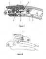
- FIGS 3 to 8 illustrate a clasp for a bracelet according to a first embodiment of the invention.
- This clasp comprises two blades 10, articulated according to a principle similar to that described in the document EP1654950 which will not be detailed again at this stage.
- This uses two torsion springs 25, in particular two helical springs, arranged around the hinge axis 24 of the coupling lever 23.
- the invention is thus implemented at the hinge joint. an element for locking / unlocking a bracelet clasp.
- the clasp according to this first embodiment comprises a first blade 10 carrying a latching pin 13 to a first end carrying a first bracelet mesh composed of several links 18 hingedly connected by pins 19. These elements are more particularly visible on Figures 6 to 8 .
- This first mesh is an end of a first bracelet strand.
- This first blade 10 is hingedly connected to a second blade 20 about a hinge axis 11 at its second end.
- This second blade 20 carries towards its free end opposite to the hinge axis 11 a hooking lever 23 which comprises a hook cooperating with the hooking stud 13.
- the hooking lever 23 is articulated about an axis articulation 24 which extends over substantially the entire width of the clasp, in a direction perpendicular to its direction longitudinal.
- Two torsion springs are arranged around this hinge axis 24, as will be detailed below.
- a bracelet mesh is further arranged at the same end of the second blade 20, and constitutes an end of the second bracelet strand.
- This mesh comprises a central link 28 and two edge links 22 connected to the hinge axis 24 of the engagement lever 23. This first row of links is linked to other links 28 '. All these links of the mesh are linked by pins 29.
- a gripping member 30 is integral with the hooking lever 23 to facilitate its handling.
- the different links 18, 22, 28, 28 'of the two blades 10, 20 form a continuous assembly, in which the gripping member 30 is integrated in a discrete but easily manipulable manner, between the links clasp, to ensure an attractive aesthetic.
- the hooking lever 23 is in a form similar to that of a bracelet link. The bracelet thus has a continuous appearance all around the wrist in the closed configuration of the clasp, which is finally very little visible, especially due to its small thickness due to the reduced size of its mechanism, explained below.
- the figure 5 is a perspective view of a spring 25 used in this first embodiment.
- a spring 25 comprises a helical central part consisting of turns, filling the elastic function of the spring, and disposed between two ends 36, 37.
- Each of these ends 36, 37 comprises a substantially cylindrical shape, the periphery of which comprises at least a protrusion, respectively 38, 39.
- circular cutouts 32, 33 are made in the center of respectively each of the two ends 36, 37, and extend in the direction of the axis of the spring.
- the clasp uses two springs as described above, symmetrical with respect to the longitudinal plane of the clasp and aligned.
- FIGS. 6a and 6b thus illustrate a section of the clasp according to the first embodiment along a longitudinal plane II at the first end 36 of a spring 25. It appears that this end 36 is arranged so that its projection 38 is housed within an opening arranged within the hooking lever 23, this opening forming a counter-form of the projection 38.
- This architecture allows to block in rotation, that is to say in both directions of rotation, the end 36 of the spring 25 relative to the hooking lever 23.
- this against-shape may have an ideal shape that ensures a true blocking of the projection and therefore the end of the spring or alternatively may be substantially complementary only leave a radial clearance at the connection of the projection and its counter-form, or even allow an angular displacement of the projection between two stops defined by the counter-form.
- the inner cut 32 is positioned at least clearance around the hinge axis 24.
- FIGS. 7a and 7b illustrate the same clasp at the central portion of the spring 25. There is thus a portion of turn of the central portion 35 of the spring 25 which surrounds clearance the hinge axis 24.
- Figures 8a and 8b illustrate a section of the clasp according to the first embodiment in a longitudinal plane at the second end 37 of a spring 25. Its projections 39 cooperate with corresponding openings, which are substantially complementary or even complementary, and which are arranged in the inner surface of an edge link 22 of the clasp, which makes it possible to lock this second end in rotation.
- the latter can be driven, welded, or brazed to the edge link 22 to improve its fixation, or fixed by any other medium like collage. Alternatively, it is not fixed but blocked with clearance, or limited radial (angular) movement.
- the inner cutout 33 is positioned at least clearance around the hinge axis 24.
- the inside diameter obtained by at least one lateral cutout 32, 33 is smaller than the inner diameter of the turns of the central portion 35 of the spring 25.
- the outside diameter (excluding the projections 38, 39) of the ends 36, 37 (or at least one end) of the spring 25 is greater than the outer diameter of the turns of the central portion 35 of the spring.
- the projections are in the extension of the outer diameter of the ends 36, 37.
- FIGS. 9 to 15 illustrate a clasp according to a second embodiment of the invention.
- This clasp in particular illustrated by Figures 9 and 10 , likewise comprises two articulated blades, but, unlike the previous embodiment, is provided with a cover which covers the mechanism in the closed position of the clasp.
- This cover comprises a first portion in the form of movable tab 41, pivotable by its two lateral ends, which is integral with a hooking lever 23 which performs the function of the hooking lever of the previous embodiment, and a second fixed part 40.
- a different spring 25 represented by the Figures 11 and 12 , is used. It always comprises a central portion 35 comprising turns, to fulfill the elastic function, between two ends 36, 37. However, these two ends have a slightly different shape which will be explained with reference to the following figures.
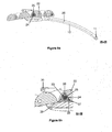
- FIGS. 13a and 13b thus illustrate a cut of the clasp along a longitudinal plane II at the first end 36 of a spring 25. It appears that this end 36 is arranged so that the projection 38 is housed within an opening arranged within an integral portion of the second fixed portion 40 of the cover, forming a counter-shape of the projection 38. This architecture is used to lock in rotation the end 36 of the spring 25 relative to the cover.
- the figures 14a and 14b illustrate this same clasp by a section II-II at the central portion of the spring 25. There is thus a portion of turn of the spring 25 which surrounds a bar, in particular a spring bar or removable bar, forming a hinge axis 24.
- Figures 15a and 15b illustrate a III-III section of the clasp at the second end 37 of a spring 35.
- Its projection 39 cooperates with corresponding openings arranged in the inner surface of the tab mobile 41, which allows to lock in rotation this second end relative to the movable tab.
- This second end also comprises a flat portion 34 on its circumference, to cooperate with a countersink of a mesh integral with the lid. This flat part makes it possible, on the other hand, to form a stop 31 which delimits the lateral fretting of the spring 25.
- this second end 37 of the spring 25 furthermore comprises a radial through cut 43, complementary to a cut made in FIG. mobile tab 41 of the cover, to allow mounting / disassembly of the cover in a conventional manner by allowing free access to the ends of the bar 24.
- the diameter of at least one lateral cutout 32, 33 of one end 36, 37 of the spring 25 is smaller than the inside diameter of the turns of the central portion 35 of the spring 25 so that the spring 25 can be pivoted with less play on the axis 24.
- the outside diameter (ignoring the projections 38, 39) of the ends 36, 37 (or at least one end) of the spring 25 is greater than the outside diameter. turns of the central portion 35 of the spring.
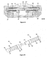
- FIGS. 16 to 23 illustrate a clasp according to a third embodiment of the invention.
- This clasp in particular illustrated by Figures 16 and 17 , is very close to the previous realization. It differs in that the hooking lever 23, secured to the movable tab 41 of the cover, is pivotable in its central portion via a central link forming a component integral with the engaging lever of the first mode of production.
- a single spring 25 is used, represented by the Figures 18 and 19 .
- This spring comprises two elastic zones called “spring” 55 composed of turns, respectively arranged between a central portion 50 and each of the two ends 56, 57 of the spring.
- Each end may comprise shapes similar to the embodiments described above, and include at least one projection 58, 59.
- the central portion 50 comprises a cylindrical shape also comprising at least one projection 51.
- through cuts 52, 53 are also provided at the two ends 56, 57 and the central portion 50 of the spring. Other aspects of this jurisdiction are detailed below.
- FIGS 20a and 20b thus illustrate a section of the clasp along a longitudinal plane II at the central portion 50 of the spring. It appears that the projection 51 is housed within an opening formed within the mobile mesh which is linked to the hooking lever 23 and the movable tab 41 of the cover, this opening forming a counterform of the projection .
- This architecture makes it possible to block in rotation the central portion 50 of the spring 25 relative to this movable tab 41.
- the figures 21a and 21b illustrate this same clasp by a section at a spring intermediate zone 55 of the spring 25. There is thus a portion of turn of the spring 25 which surrounds clearance a bar forming a hinge pin 24.
- Figures 22a and 22b illustrate a section of the clasp at one end 57 of the spring 25.
- the architecture of this solution is symmetrical about a median plane and one could consider here in an identical way any one of the two lateral parts of the clasp.
- the projection 59 cooperates with corresponding openings arranged in edge pieces integral with the fixed part 40 of the cover, which makes it possible to lock the two ends of the spring 25 in rotation.
- the mounting of this clasp requires to assemble and disassemble the hinge pin 24 and the spring 25.
- the projections 58, 59 arranged at the ends 56, 57 of the spring 25 allow the passage of the opening of the mobile mesh which is secured to the hooking lever 23, which receives the projection 51 of the central portion of the spring 25, as illustrated by the figure 23 .
- the projections 58, 59, 51 are for example aligned in this embodiment.
- the through cuts 43 allow the assembly and disassembly of the lid of the clasp, as in the previous embodiment.
- the diameter of the circular cutout of the central portion 50 of the spring 25 is smaller than the inner diameter of the turns of the two spring zones 55, and less than or equal to the diameter of the circular cutouts 52, 53 of the ends 56, 57 of the spring 25. Moreover, this inner diameter of the central portion 50 of the spring 25 pivots with less play on the hinge axis 24.
- the outer diameter (excluding the projections 51, 58, 59) of the central portion 50 of the spring 25, or even the ends 56, 57 (or at least one end) of the spring 25 is greater than the outer diameter of the turns of the spring zones 55 of the spring.
- FIGS. 24 to 31 illustrate a clasp according to a fifth embodiment of the invention.
- This clasp differs from the previous embodiments in that the torsion spring is not associated with a separate hinge axis, but fills only the additional function of hinge axis.
- the Figures 24 to 26 illustrate this fourth embodiment in the case of a clasp without cover, close to the embodiment according to the first embodiment.
- a single spring 25 is used, represented by the Figures 27 and 28 .
- This spring 25 comprises a helical central part consisting of turns, disposed between two ends 36, 37.
- Each of these ends comprises a substantially cylindrical shape, the periphery of which comprises at least one projection, respectively 38, 39.
- Each end comprises more elongated cylindrical portions 46, 47 which fulfill the radial guide function.
- Other aspects of this jurisdiction are detailed below.
- FIGS 31a and 31b show a sectional view of the clasp according to a longitudinal plane II-II according to the fourth embodiment at a first end 37 of the spring 25.
- the projection 39 of the spring 25 cooperates with a corresponding opening arranged in the engaging lever 23, which makes it possible to lock this end of the spring 25 in rotation.
- FIGS 31a and 31b show a sectional view of the clasp along a longitudinal plane III-III according to the fifth embodiment at the second end 36 of the spring 25.
- the projection 38 of the spring cooperates with a corresponding opening arranged in an edge link 22, this which makes it possible to lock this end of the spring 25 in rotation.
- the spring 25 comprises outer surfaces of larger diameter at least one of its ends, which makes it possible to form guide surfaces of the pivoting movement, and to make the movement independent of the rest of the fluctuations of the spring.
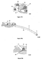
- the Figures 32 to 38 illustrate a clasp according to a fifth embodiment of the invention.
- This clasp differs from the previous embodiment in that it uses two torsion springs, which remain unassociated with a separate hinge axis, but only fulfill the additional function of axis of articulation.
- the Figures 32 to 34 illustrate this fifth embodiment in the case of a clasp without cover, close to the embodiment according to the first embodiment and the previous embodiment.
- the single spring of the previous embodiment is replaced by two springs 25, 25 ', shown in FIG. figure 35 .
- Each of these springs 25, 25 ' comprises a central portion 35, 35' consisting of helical turns, filling the function of "spring", disposed between two ends 36, 37; 36 ', 37'.
- Each of these ends comprises a substantially cylindrical shape, the periphery of which comprises at least one protrusion, respectively 38, 39, 38 '(not visible), 39'.
- the two ends 36, 37 'respectively of the two springs 25, 25' comprise extensions 66, 67 'forming complementary connecting means, allowing the connection of the two springs 25, 25'.
- the first spring 25 comprises an extension 66 forming an axial projection intended to be housed in a bore of the extension 67 'of the second spring 25'. This connection of the two springs is particularly visible on the figure 34 .
- FIGS. 36a and 36b represent a sectional view of this clasp along a longitudinal plane II at its central portion. This cutting plan passes at the level of the extension 67 'of the second spring 25. It is also seen that the central link 28 of the clasp surrounds this extension 67'.
- the figures 37a and 37b show a sectional view of the clasp along a longitudinal plane II-II at a first end 36 of the first spring 25.
- the projection 38 of the spring 25 cooperates with a corresponding opening arranged in the attachment lever 23, which allows to lock in rotation this end of the spring 25.
- the projection 39 'of the second spring 25' is also housed in an aperture forming a counter-form of the same hooking lever 23.
- the Figures 38a and 38b show a sectional view of the clasp at the second end 37 of the first spring 25.
- the projection 39 of the spring cooperates with a corresponding opening arranged in an edge link 22, which makes it possible to lock this end of the spring 25 in rotation.
- the projection 38 'of the second spring 25' is also housed in a counter-shaped opening of an opposite edge link 22.
- FIGS. 39 to 45 illustrate a clasp according to a sixth embodiment of the invention. These illustrate this sixth embodiment in the case of a clasp without cover, close to the embodiment according to the previous embodiment.
- the single spring 25 comprises a central part 35 consisting of a torsion wire, fulfilling the function of "spring", on which are reported the first and second parts 36, 37.
- these parts can be reported by welding, especially by laser welding, or by soldering or gluing. They can also be secured to the twisting thread by crushing material.
- geometric conformations, including flats 86, 87, are provided on the parts 36 and 37 so as to allow crushing of the torsion wire at its ends.
- the figure 42 illustrates a first embodiment of the spring in which the section of the torsion wire is circular.
- the section of the torsion wire has for example a diameter of the order of 0.5 mm.
- the figure 43 illustrates a second embodiment of the spring in which the section of the torsion wire is square.
- this section may have any kind of adapted geometry so as to generate an adequate return torque.
- the section of the twist wire can also be solid or hollow.
- this twisting wire can be machined from a spring material such as that known by its trademark Nivaflex. It could also be made of Phynox or any other cobalt-based alloy.
- This twist wire could also be machined from a shape memory alloy such as that known by its trademark Nitinol, or titanium. This twist wire can also be hardened.
- FIGS 44a and 44b are a sectional view of the clasp along a longitudinal plane II at its central portion.
- This cutting plane passes at a first portion 36 of the spring 25. It appears that this portion 36 is arranged so that its projection 38 is housed within an opening formed in the central link 28, this opening forming A counter-shape of the projection 38.
- This architecture makes it possible to block in rotation, that is to say in both directions of rotation, the portion 36 of the spring 25 relative to the central link 28, and also relative to the edge links. 22 of the clasp, the latter being secured to the central link 28 by an associated assembly axis.
- the figures 45a and 45b show a sectional view of the clasp along a longitudinal plane II-II at a second portion 37 of the first spring 25.
- the projection 39 of the spring 25 cooperates with a corresponding opening arranged in the attachment lever 23, this opening forming a counter-form of the projection 39.
- This architecture makes it possible to block in rotation, that is to say in both directions of rotation, the portion 37 of the spring 25 relative to the engaging lever 23.
- the Guiding the rotation of the latching lever 23 is provided by the outer diameter of the portions 36, 37 or a portion of the portions 36, 37 (disregarding the projections 38, 39).
- the parts 36 and 37 also implement the connecting axis between the two components.
- At least one torsion spring is used, for the implementation of an elastic articulation between two components of a clock mechanism, which has the advantage of minimizing the bulk compared with to the solutions of the state of the art.
- This spring may for example comprise helical turns or one or more torsion wire.
- a spring has at least one projection which is designed to engage in a counter-shape that is substantially complementary, or even complementary, to angularly block the corresponding zone of the spring to the component to which it is linked. that is blocking its rotation, in both directions of rotation.
- this counter-form may allow a certain angular displacement of the projection.
- the counterform therefore defines two stops which each block a rotation in a given direction of the spring, which limit the rotation in a certain angular displacement between the two stops. This approach makes it possible to angularly index the two articulated components.
- particular areas of the spring are also provided to form guide surfaces, which implement the function of guiding the rotational movement of the two watch components, to overcome the defects, dispersions, shape fluctuations of other parts.
- the spring in particular the parts comprising the turns in the case of a helical torsion spring, or comprising a torsion wire in another case, this or these other part (s) fulfilling the elastic function.
- these particular areas are advantageously in cylindrical base shapes with different diameters for a connection with less play with the watch components.
- such a link with less game means that the game is low enough so that the two components in connection can be rotated relative to each other, but with a very low mobility in other directions, to provide a function of guiding the rotational movement.
- this clearance will be less than 0.15 mm, or even less than 0.1 mm, for example around a nominal clearance of about 0.07 mm.
- D1-D2 the guiding surface of the spring and the corresponding surface of the watch component in connection with a smaller clearance are both substantially cylindrical with respective diameters D1 and D2, it will preferably be chosen
- one or more torsion springs can be used. In the case of several springs, they can be independent or assembled.
- certain zones have been designed to angularly block and / or guide the rotational movement of the watch components: these zones have been positioned towards the ends and / or at the center of the spring. They could alternatively be at any other spring location.
- at least one protrusion has been used to form an angular locking element.
- any radial or longitudinal projection, a Toothing, a flat, a counterbore, and / or a bore, etc. may be used.
- the locking in rotation must be interpreted as an arrangement that allows to completely block any rotation, or that limits this rotation by two stops that each prevent rotation in a certain direction and finally which limit the degree of freedom in a certain angular displacement between the two stops.
- This angular deflection is preferably low, less than or equal to 20 degrees, or even 10 degrees.
- this or these torsion spring (s) are advantageously arranged along the axis of rotation of the two watch components. They can be associated with a hinge axis existing physically in the form of an axis or a bar or without any other element, then themselves forming the axis of physical articulation of the articulated components. Alternatively, this axis of rotation is formed for example by one or more spring (s) of the arrangement, without adding a separate physical axis, the axis of rotation or axis of connection between the two components being then not directly materialized.
- the invention has been illustrated from a bracelet clasp associated with a wristwatch, which is also also concerned as such by this invention, and more precisely at the locking mechanism of this clasp, between a movable element such as a lever or a cam implementing the locking and unlocking and another separate fixed component of the clasp.
- this principle can be implemented for any elastic link articulated between two watch components, whether this movement is a pure rotation or more complex, such as a rotation combined with another displacement.
- the principle of the invention can be implemented between any two components of a timepiece.
- many other embodiments of the invention can be easily deduced by the combination of the different embodiments illustrated above, or by integrating any previously described spring between two articulated watch components.
- a first solution consists in machining a spring material such as that known by its trademark Nivaflex. Slots of the order of 0.4 mm can then be made, for example by laser cutting.
- a second solution consists in making a spring in several parts.
- the figure 47 illustrating by way of example the making of a particular spring from three distinct parts.
- a first step of this method therefore comprises the manufacture of several distinct parts of the spring, in particular by separating the zone filling the elastic function of the locking zones in rotation and / or guiding. So, taking again the example illustrated by the figure 47 a central portion 35 is obtained from a wound wire previously hardened. Then, both ends 36, 37 are machined from a more conventional material, such as stainless steel.
- a second step then consists in assembling the parts distinct. This assembly can for example be done by laser welding. To minimize the stresses during these welds, the ends to be welded of each of these distinct parts may have a cut-out staircase 81.
- This manufacture uses a wire of preferably square or rectangle section, with a spacing between the turns chosen to obtain the recall couple wanted. This manufacturing method makes it possible in particular to generate contact between the turns of the spring of the central portion 35 to reach a maximum torque.
Description
La présente invention concerne un agencement pour la liaison articulée élastique entre deux composants d'un assemblage horloger, notamment pour un bracelet de montre-bracelet, disposé soit au niveau d'un fermoir, soit au niveau des mailles de ce bracelet. Elle porte aussi sur un fermoir, un bracelet et une montre-bracelet en tant que tels comprenant un tel agencement.The present invention relates to an arrangement for the elastic articulated connection between two components of a watch assembly, particularly for a wristwatch bracelet, arranged either at a clasp or at the meshes of the bracelet. It also relates to a clasp, a bracelet and a wristwatch as such comprising such an arrangement.
La
Cette réalisation permet de garantir une très bonne sécurité de verrouillage tout en optimisant la force requise pour l'ouverture du fermoir, ce qui en fait une solution très satisfaisante en termes de sécurité de fermeture et de manipulation.This embodiment makes it possible to guarantee very good locking security while optimizing the force required for the opening of the clasp, which makes it a very satisfactory solution in terms of security of closure and manipulation.
Ce même document décrit un second mode de réalisation, représenté par la
De nombreux autres documents décrivent d'autres agencements pour la liaison entre deux composants d'un bracelet pour montre-bracelet, qui reposent toutes sur l'utilisation de moyens de rappel élastiques à base de ressorts hélicoïdaux travaillant en compression.Numerous other documents describe other arrangements for the connection between two components of a wristwatch bracelet, all of which rely on the use of resilient return means based on coil springs working in compression.
A titre d'exemple, les documents
Les documents
Le document
Finalement, toutes ces solutions existantes ne permettent pas d'atteindre un compromis maximal entre la sécurité du verrouillage ou de l'articulation élastique, la convivialité de son fonctionnement, et l'encombrement de la solution. En effet, les solutions les plus performantes présentent l'inconvénient d'un encombrement important, ce qui devient incompatible avec certains aspects esthétiques recherchés et limite leurs utilisations. D'autres solutions moins encombrantes sont en revanche nettement moins performantes.Finally, all these existing solutions do not make it possible to reach a maximum compromise between the safety of the locking or the elastic articulation, the user-friendliness of its operation, and the size of the solution. Indeed, the most powerful solutions have the disadvantage of a large footprint, which becomes incompatible with certain aesthetic aspects sought and limits their use. Other less bulky solutions are however significantly less efficient.
On note de plus que les réalisations précitées ont été développées dans le cadre d'un fermoir pour bracelet mais peuvent également s'appliquer pour la liaison entre des mailles de bracelet ou plus généralement pour tous composants horlogers articulés élastiquement entre eux. Par exemple, cette solution peut également s'appliquer pour la liaison entre une boîte de montre et un brin de bracelet.It is further noted that the above-mentioned embodiments have been developed in the context of a bracelet clasp but can also be applied for the connection between bracelet stitches or more generally for all clock components hinged elastically to each other. For example, this solution can also be applied for the connection between a watch case and a bracelet strand.
Ainsi, un objet général de l'invention est de proposer une solution de liaison articulée élastique entre deux composants d'un assemblage horloger, qui atteint un compromis optimal entre la performance de l'assemblage élastique et son encombrement.Thus, a general object of the invention is to provide an elastic articulated connection solution between two components of a watch assembly, which achieves an optimal compromise between the performance of the elastic assembly and its bulk.
Notamment, une telle solution est plus particulièrement recherchée pour une application au sein d'un fermoir de bracelet, ou pour l'articulation de lames ou mailles de bracelet pour montre-bracelet.In particular, such a solution is more particularly sought for an application within a bracelet clasp, or for the articulation of blades or bracelet stitches for a wristwatch.
A cet effet, l'invention repose sur un agencement pour la liaison articulée élastique entre deux composants d'un assemblage horloger, caractérisé en ce qu'il comprend au moins un ressort travaillant en torsion pour générer l'effet élastique de l'articulation.For this purpose, the invention is based on an arrangement for the elastic articulated connection between two components of a watch assembly, characterized in that it comprises at least one spring working in torsion to generate the elastic effect of the joint.
L'invention est plus précisément définie par les revendications.The invention is more precisely defined by the claims.
Ces objets, caractéristiques et avantages de la présente invention seront exposés en détail dans la description suivante de modes de réalisation particuliers faits à titre non-limitatif en relation avec les figures jointes parmi lesquelles :
- La
figure 1 représente une vue en coupe d'un fermoir selon une première solution de l'état de la technique. - La
figure 2 représente une vue en coupe d'un fermoir selon une seconde solution de l'état de la technique. - La
figure 3 représente une vue en perspective de dessus d'un fermoir selon un premier mode de réalisation de l'invention. - La
figure 4 représente une vue de dessus du fermoir selon le premier mode de réalisation dans lequel les éléments importants de la solution sont montrés par transparence, notamment les ressorts de torsion. - La
figure 5 représente une vue en perspective d'un ressort utilisé dans le premier mode de réalisation de l'invention. - Les
figures 6a à 8a représentent des vues en coupe selon respectivement des plans longitudinaux I-I, II-II, III-III du fermoir selon le premier mode de réalisation de la présente invention. - Les
figures 6b à 8b représentent des vues agrandies du fermoir selon les vues en coupe précédentes. - La
figure 9 représente une vue en perspective de dessus d'un fermoir selon un deuxième mode de réalisation de l'invention. - La
figure 10 représente une vue de dessus du fermoir selon le deuxième mode de réalisation dans lequel les éléments importants de la solution sont montrés par transparence, notamment les ressorts de torsion. - La
figure 11 représente une vue en perspective d'un ressort utilisé dans le deuxième mode de réalisation de l'invention. - La
figure 12 représente une vue de côté du ressort utilisé dans le deuxième mode de réalisation de l'invention. - Les
figures 13a à 15a représentent des vues en coupe selon respectivement des plans longitudinaux I-I, II-II, III-III du fermoir selon le deuxième mode de réalisation de la présente invention. - Les
figures 13b à 15b représentent des vues agrandies du fermoir selon les vues en coupe précédentes. - La
figure 16 représente une vue en perspective de dessus d'un fermoir selon un troisième mode de réalisation de l'invention. - La
figure 17 représente une vue de dessus du fermoir selon le troisième mode de réalisation dans lequel les éléments importants de la solution sont montrés par transparence, notamment le ressort de torsion. - La
figure 18 représente une vue en perspective d'un ressort utilisé dans le troisième mode de réalisation de l'invention. - La
figure 19 représente une vue de côté du ressort utilisé dans le troisième mode de réalisation de l'invention. - Les
figures 20a à 22a représentent des vues en coupe selon respectivement des plans longitudinaux I-I, II-II, III-III du fermoir selon le troisième mode de réalisation de la présente invention. - Les
figures 20b à 22b représentent des vues agrandies du fermoir selon les vues en coupe précédentes. - La
figure 23 représente une vue schématique du montage d'un ressort au sein d'un fermoir selon le troisième mode de réalisation de la présente invention. - La
figure 24 représente une vue en perspective de dessus d'un fermoir selon un quatrième mode de réalisation de l'invention. - La
figure 25 représente une vue de dessus du fermoir selon le quatrième mode de réalisation dans lequel les éléments importants de la solution sont montrés par transparence, notamment le ressort de torsion. - La
figure 26 représente une vue en coupe selon un plan transversal IV-IV comprenant le ressort de torsion du quatrième mode de réalisation de l'invention. - Les
figures 27 et 28 représentent des vues en perspective d'un ressort utilisé dans le quatrième mode de réalisation de l'invention. - Les
figures 29a à 31 a représentent des vues en coupe selon respectivement des plans longitudinaux I-I, II-II, III-III du fermoir selon le quatrième mode de réalisation de la présente invention. - Les
figures 29b à 31b représentent des vues agrandies du fermoir selon les vues en coupe précédentes. - La
figure 32 représente une vue en perspective de dessus d'un fermoir selon un cinquième mode de réalisation de l'invention. - La
figure 33 représente une vue de dessus du fermoir selon le cinquième mode de réalisation dans lequel les éléments importants de la solution sont montrés par transparence, notamment les ressorts de torsion. - La
figure 34 représente une vue en coupe selon un plan transversal IV-IV comprenant les ressorts de torsion du cinquième mode de réalisation de l'invention. - La
figure 35 représente une vue en perspective des ressorts utilisés dans le cinquième mode de réalisation de l'invention. - Les
figures 36a à 38a représentent des vues en coupe selon respectivement des plans longitudinaux I-I, II-II, III-III du fermoir selon le cinquième mode de réalisation de la présente invention. - Les
figures 36b à 38b représentent des vues agrandies du fermoir selon les vues en coupe précédentes. - La
figure 39 représente une vue en perspective de dessus d'un fermoir selon un sixième mode de réalisation de l'invention. - La
figure 40 représente une vue de dessus du fermoir selon le sixième mode de réalisation dans lequel les éléments importants de la solution sont montrés par transparence, notamment le ressort de torsion. - La
figure 41 représente une vue en coupe selon un plan transversal III-III comprenant le ressort de torsion du sixième mode de réalisation de l'invention. - La
figure 42 représente une vue en perspective d'une première variante de ressort utilisé dans le sixième mode de réalisation de l'invention. - La
figure 43 représente une vue en perspective d'une deuxième variante de ressort utilisé dans le sixième mode de réalisation de l'invention. - Les
figures 44a et 45a représentent des vues en coupe selon respectivement des plans longitudinaux I-I, II-II du fermoir selon le sixième mode de réalisation de la présente invention. - Les
figures 44b et45b représentent des vues agrandies du fermoir selon les vues en coupe précédentes. - La
figure 46 représente une liaison articulée entre deux mailles d'un bracelet selon un septième mode de réalisation de l'invention. - La
figure 47 représente schématiquement une étape de principe d'un procédé de fabrication d'un ressort de torsion selon un mode de réalisation de l'invention.
- The
figure 1 represents a sectional view of a clasp according to a first solution of the state of the art. - The
figure 2 represents a sectional view of a clasp according to a second solution of the state of the art. - The
figure 3 represents a perspective view from above of a clasp according to a first embodiment of the invention. - The
figure 4 is a top view of the clasp according to the first embodiment in which the important elements of the solution are shown by transparency, including the torsion springs. - The
figure 5 is a perspective view of a spring used in the first embodiment of the invention. - The
Figures 6a to 8a are sectional views respectively along the longitudinal planes II, II-II, III-III of the clasp according to the first embodiment of the present invention. - The
Figures 6b to 8b represent enlarged views of the clasp according to the previous sectional views. - The
figure 9 represents a perspective view from above of a clasp according to a second embodiment of the invention. - The
figure 10 is a top view of the clasp according to the second embodiment in which the important elements of the solution are shown by transparency, including the torsion springs. - The
figure 11 is a perspective view of a spring used in the second embodiment of the invention. - The
figure 12 represents a side view of the spring used in the second embodiment of the invention. - The
Figures 13a to 15a are sectional views respectively along the longitudinal planes II, II-II, III-III of the clasp according to the second embodiment of the present invention. - The
Figures 13b to 15b represent enlarged views of the clasp according to the previous sectional views. - The
figure 16 represents a perspective view from above of a clasp according to a third embodiment of the invention. - The
figure 17 is a top view of the clasp according to the third embodiment in which the important elements of the solution are shown by transparency, including the torsion spring. - The
figure 18 is a perspective view of a spring used in the third embodiment of the invention. - The
figure 19 represents a side view of the spring used in the third embodiment of the invention. - The
Figures 20a to 22a are cross-sectional views respectively along the longitudinal planes II, II-II, III-III of the clasp according to the third embodiment of the present invention. - The
Figures 20b to 22b represent enlarged views of the clasp according to the previous sectional views. - The
figure 23 is a schematic view of mounting a spring within a clasp according to the third embodiment of the present invention. - The
figure 24 is a perspective view from above of a clasp according to a fourth embodiment of the invention. - The
figure 25 represents a top view of the clasp according to the fourth embodiment in which the important elements of the solution are shown by transparency, in particular the torsion spring. - The
figure 26 is a sectional view along a transverse plane IV-IV comprising the torsion spring of the fourth embodiment of the invention. - The
Figures 27 and 28 are perspective views of a spring used in the fourth embodiment of the invention. - The
Figures 29a to 31 a represent sectional views respectively along the longitudinal planes II, II-II, III-III of the clasp according to the fourth embodiment of the present invention. - The
Figures 29b to 31b represent enlarged views of the clasp according to the previous sectional views. - The
figure 32 is a perspective view from above of a clasp according to a fifth embodiment of the invention. - The
figure 33 is a top view of the clasp according to the fifth embodiment in which the important elements of the solution are shown by transparency, including the torsion springs. - The
figure 34 is a sectional view along a transverse plane IV-IV comprising the torsion springs of the fifth embodiment of the invention. - The
figure 35 is a perspective view of the springs used in the fifth embodiment of the invention. - The
Figures 36a to 38a are sectional views respectively along the longitudinal planes II, II-II, III-III of the clasp according to the fifth embodiment of the present invention. - The
Figures 36b to 38b represent enlarged views of the clasp according to the previous sectional views. - The
figure 39 represents a perspective view from above of a clasp according to a sixth embodiment of the invention. - The
figure 40 represents a top view of the clasp according to the sixth embodiment in which the important elements of the solution are shown by transparency, in particular the torsion spring. - The
figure 41 is a sectional view along a transverse plane III-III comprising the torsion spring of the sixth embodiment of the invention. - The
figure 42 is a perspective view of a first spring variant used in the sixth embodiment of the invention. - The
figure 43 is a perspective view of a second spring variant used in the sixth embodiment of the invention. - The
Figures 44a and 45a are cross-sectional views respectively along the longitudinal planes II, II-II of the clasp according to the sixth embodiment of the present invention. - The
figures 44b and45b represent enlarged views of the clasp according to the previous sectional views. - The
figure 46 represents an articulated connection between two meshes of a bracelet according to a seventh embodiment of the invention. - The
figure 47 schematically represents a step of principle of a method of manufacturing a torsion spring according to one embodiment of the invention.
L'invention repose donc sur l'utilisation d'au moins un ressort travaillant en torsion. Comme cela va être illustré par la suite, l'utilisation d'une telle solution permet de réduire fortement l'encombrement de la solution.The invention is therefore based on the use of at least one spring working in torsion. As will be illustrated later, the use of such a solution can greatly reduce the size of the solution.
Pour la suite de la description, les mêmes références seront utilisées pour désigner des éléments équivalents sur les différents modes de réalisation de l'invention pour faciliter leur compréhension.For the rest of the description, the same references will be used to designate equivalent elements on the various embodiments of the invention to facilitate their understanding.
Les
Ainsi, le fermoir selon ce premier mode de réalisation comprend une première lame 10 portant un plot d'accrochage 13 vers une première extrémité portant une première maille de bracelet composée de plusieurs maillons 18 liés de manière articulée par des axes 19. Ces éléments sont plus particulièrement visibles sur les
Cette seconde lame 20 porte vers son extrémité libre opposée à l'axe d'articulation 11 un levier d'accrochage 23 qui comprend un crochet coopérant avec le plot d'accrochage 13. Le levier d'accrochage 23 est articulé autour d'un axe d'articulation 24 qui s'étend sur sensiblement toute la largeur du fermoir, dans une direction perpendiculaire à sa direction longitudinale. Deux ressorts 25 de torsion sont agencés autour de cet axe d'articulation 24, comme cela sera détaillé ci-dessous. Une maille de bracelet est de plus agencée à cette même extrémité de la seconde lame 20, et constitue une extrémité du second brin de bracelet. Cette maille comprend un maillon central 28 et deux maillons de bord 22 liés à l'axe d'articulation 24 du levier d'accrochage 23. Cette première rangée de maillons est liée à d'autres maillons 28'. Tous ces maillons de la maille sont liés par des axes 29. Enfin, un organe de préhension 30 est solidaire du levier d'accrochage 23 pour faciliter sa manipulation. Comme cela est particulièrement visible sur la
La
Le fonctionnement de la solution selon ce premier mode de réalisation va mieux être illustré par les vues en coupes des
Les
Les
Enfin, les
Le diamètre intérieur obtenu par au moins une découpe latérale 32, 33 est inférieur au diamètre intérieur des spires de la partie centrale 35 du ressort 25. De plus, le diamètre extérieur (en faisant abstraction des saillies 38, 39) des extrémités 36 ,37 (ou d'au moins une extrémité) du ressort 25 est supérieur au diamètre extérieur des spires de la partie centrale 35 du ressort. Préférentiellement, les saillies sont dans le prolongement du diamètre extérieur des extrémités 36, 37. Par cette construction, le guidage de la rotation du levier d'accrochage 23 est assuré par les extrémités 36, 37 du ressort, en contact dans sa découpe intérieure avec l'axe d'articulation 24 et dans sa partie extérieure avec d'une part le levier d'accrochage 23 et d'autre part un maillon de bord 22. Ce guidage devient ainsi indépendant des fluctuations géométriques des spires de sa partie centrale. Les extrémités du ressort forment donc des surfaces de guidage du mouvement relatif des deux composants horlogers, ce qui stabilise ce mouvement et notamment son rappel élastique.The inside diameter obtained by at least one
D'autres modes de réalisation de fermoirs vont maintenant être décrits, mettant en oeuvre d'autres types de mécanismes de verrouillage/déverrouillage d'un fermoir, avec d'autres moyens élastiques de torsion. Comme l'invention ne porte pas sur le dispositif de verrouillage/déverrouillage d'un fermoir en tant que tel, ce dernier sera décrit de manière succincte par la suite.Other embodiments of clasps will now be described, implementing other types of mechanisms for locking / unlocking a clasp, with other elastic torsion means. As the invention does not relate to the locking / unlocking device of a clasp as such, the latter will be briefly described later.
Les
Ce fermoir, notamment illustré par les
Dans cette réalisation, un ressort 25 différent, représenté par les
Les
Les
Enfin, les
Comme dans le mode de réalisation précédent, le diamètre d'au moins une découpe latérale 32, 33 d'une extrémité 36, 37 du ressort 25 est inférieur au diamètre intérieur des spires de la partie centrale 35 du ressort 25 de sorte que le ressort 25 peut pivoter à moindre jeu sur l'axe 24. De plus, le diamètre extérieur (en faisant abstraction des saillies 38, 39) des extrémités 36, 37 (ou d'au moins une extrémité) du ressort 25 est supérieur au diamètre extérieur des spires de la partie centrale 35 du ressort. Par cette construction, le guidage de la rotation du levier d'accrochage et de l'onglet mobile est assuré par les extrémités du ressort, de manière indépendante des fluctuations géométriques des spires de sa partie centrale.As in the previous embodiment, the diameter of at least one
Les
Ce fermoir, notamment illustré par les
Dans cette réalisation, un unique ressort 25 est utilisé, représenté par les
Les
Les
Enfin, les
En remarque, le montage de ce fermoir nécessite de monter et démonter l'axe d'articulation 24 et le ressort 25. Pour cela, les saillies 58, 59 agencées aux extrémités 56, 57 du ressort 25 permettent la traversée de l'ouverture de la maille mobile qui est solidaire du levier d'accrochage 23, qui reçoit la saillie 51 de la partie centrale du ressort 25, comme illustré par la
Le diamètre de la découpe circulaire de la partie centrale 50 du ressort 25 est inférieur au diamètre intérieur des spires des deux zones ressort 55, et inférieur ou égal au diamètre des découpes circulaires 52, 53 des extrémités 56, 57 du ressort 25. De plus, ce diamètre intérieur de la partie centrale 50 du ressort 25 pivote à moindre jeu sur l'axe d'articulation 24. De manière complémentaire, le diamètre extérieur (en faisant abstraction des saillies 51, 58, 59) de la partie centrale 50 du ressort 25, voire aussi des extrémités 56 ,57 (ou d'au moins une extrémité) du ressort 25, est supérieur au diamètre extérieur des spires des zones ressort 55 du ressort. Par cette construction, le guidage de la rotation du levier d'accrochage et de l'onglet mobile du couvercle est assuré de manière indépendante des fluctuations géométriques des spires de ses zones ressort.The diameter of the circular cutout of the
Les
Ce fermoir diffère des réalisations précédentes en ce que le ressort de torsion n'est pas associé à un axe d'articulation distinct, mais remplit seul la fonction supplémentaire d'axe d'articulation. Les
Dans cette réalisation, un unique ressort 25 est utilisé, représenté par les
Les
Les
Les
Comme dans les réalisations précédentes, le ressort 25 comprend des surfaces extérieures de plus grand diamètre au niveau d'au moins une de ses extrémités, ce qui permet de former des surfaces de guidage du mouvement de pivotement, et rendre le mouvement indépendant du reste des fluctuations du ressort.As in the previous embodiments, the
Les
Ce fermoir diffère de la réalisation précédente en ce qu'il utilise deux ressorts de torsion, qui restent non associés à un axe d'articulation distinct, mais remplissent seuls la fonction supplémentaire d'axe d'articulation. Les
Dans cette réalisation, l'unique ressort du mode de réalisation précédent est remplacé par deux ressorts 25, 25', représentés sur la
Les
Les
Les
Les
Ce fermoir se distingue de la réalisation précédente en ce qu'il utilise un seul ressort de torsion agencé différemment, qui remplit seul la fonction d'axe d'articulation. Dans cette réalisation, l'unique ressort 25, dont deux variantes de réalisation sont représentées sur les
La
Les
Les
Finalement, dans tous les modes de réalisation, au moins un ressort de torsion est utilisé, pour la mise en oeuvre d'une articulation élastique entre deux composants d'un mécanisme horloger, ce qui présente l'avantage de minimiser l'encombrement par rapport aux solutions de l'état de la technique. Ce ressort peut par exemple comporter des spires hélicoïdales ou encore un, voire plusieurs, fil de torsion.Finally, in all the embodiments, at least one torsion spring is used, for the implementation of an elastic articulation between two components of a clock mechanism, which has the advantage of minimizing the bulk compared with to the solutions of the state of the art. This spring may for example comprise helical turns or one or more torsion wire.
Dans tous les modes de réalisation, un ressort présente au moins une saillie qui est prévue pour s'engager au sein d'une contre-forme sensiblement complémentaire, voire complémentaire, pour bloquer angulairement la zone correspondante du ressort au composant auquel elle est liée, c'est à dire bloquer sa rotation, dans les deux sens de rotation. Comme mentionné précédemment, dans une variante de réalisation, cette contre-forme peut autoriser un certain débattement angulaire de la saillie. Dans cette variante, la contre-forme définit donc deux butées qui bloquent chacune une rotation dans un sens donné du ressort, qui limitent la rotation dans un certain débattement angulaire entre les deux butées. Cette approche permet d'indexer angulairement les deux composants articulés.In all the embodiments, a spring has at least one projection which is designed to engage in a counter-shape that is substantially complementary, or even complementary, to angularly block the corresponding zone of the spring to the component to which it is linked. that is blocking its rotation, in both directions of rotation. As mentioned above, in an alternative embodiment, this counter-form may allow a certain angular displacement of the projection. In this variant, the counterform therefore defines two stops which each block a rotation in a given direction of the spring, which limit the rotation in a certain angular displacement between the two stops. This approach makes it possible to angularly index the two articulated components.
De plus, des zones particulières du ressort sont aussi prévues pour former des surfaces de guidage, qui mettent en oeuvre la fonction de guidage du mouvement de rotation des deux composants horlogers, pour s'affranchir des défauts, dispersions, fluctuations de forme des autres parties du ressort, notamment les parties comprenant les spires dans le cas d'un ressort hélicoïdal de torsion, ou comprenant un fil de torsion dans un autre cas, cette ou ces autre(s) partie(s) remplissant la fonction élastique. Pour cela, ces zones particulières se présentent avantageusement sous des formes à base cylindrique avec des diamètres différents pour une liaison à moindre jeu avec les composants horlogers. En remarque, une telle liaison à moindre jeu signifie donc que le jeu est suffisamment faible pour que les deux composants en liaison puissent être mobiles en rotation l'un par rapport à l'autre, mais avec une mobilité très réduite dans les autres directions, pour assurer une fonction de guidage du mouvement de rotation. De préférence, ce jeu sera inférieur à 0,15 mm, voire inférieur à 0,1 mm, par exemple autour d'un jeu nominal d'environ 0,07 mm. Ainsi, si la surface de guidage du ressort et la surface correspondante du composant horloger en liaison à moindre jeu sont toutes deux sensiblement cylindriques de diamètres respectifs D1 et D2, il sera préférentiellement choisi |D1-D2| ≤ 0,15 mm ou 0,1 mm.In addition, particular areas of the spring are also provided to form guide surfaces, which implement the function of guiding the rotational movement of the two watch components, to overcome the defects, dispersions, shape fluctuations of other parts. of the spring, in particular the parts comprising the turns in the case of a helical torsion spring, or comprising a torsion wire in another case, this or these other part (s) fulfilling the elastic function. For this, these particular areas are advantageously in cylindrical base shapes with different diameters for a connection with less play with the watch components. As a remark, such a link with less game means that the game is low enough so that the two components in connection can be rotated relative to each other, but with a very low mobility in other directions, to provide a function of guiding the rotational movement. Preferably, this clearance will be less than 0.15 mm, or even less than 0.1 mm, for example around a nominal clearance of about 0.07 mm. Thus, if the guiding surface of the spring and the corresponding surface of the watch component in connection with a smaller clearance are both substantially cylindrical with respective diameters D1 and D2, it will preferably be chosen | D1-D2 | ≤ 0.15 mm or 0.1 mm.
Naturellement, certains éléments des solutions décrites précédemment peuvent en variante se trouver sous une autre forme. Notamment, comme cela a été vu, un ou plusieurs ressorts de torsion peuvent être utilisés. Dans le cas de plusieurs ressorts, ils peuvent être indépendants ou assemblés. D'autre part, certaines zones ont été conçues pour bloquer angulairement et/ou guider le mouvement de rotation des composants horlogers : ces zones ont été positionnées vers les extrémités et/ou au centre du ressort. Elles pourraient en variante se trouver à tout autre emplacement du ressort. De plus, au moins une saillie a été utilisée pour former un élément de blocage angulaire. En variante, toute saillie radiale ou longitudinale, une denture, un méplat, un lamage, et/ou un alésage, etc., peuvent être utilisés. De plus, comme cela a été explicité précédemment, le blocage en rotation doit être interprété comme un agencement qui permet soit de bloquer totalement toute rotation, soit qui permet de limiter cette rotation par deux butées qui empêchent chacune une rotation dans un certain sens et finalement qui limitent le degré de liberté dans un certain débattement angulaire entre les deux butées. Ce débattement angulaire est de préférence faible, inférieur ou égal à 20 degrés, voire 10 degrés.Of course, some elements of the previously described solutions may alternatively be in another form. In particular, as has been seen, one or more torsion springs can be used. In the case of several springs, they can be independent or assembled. On the other hand, certain zones have been designed to angularly block and / or guide the rotational movement of the watch components: these zones have been positioned towards the ends and / or at the center of the spring. They could alternatively be at any other spring location. In addition, at least one protrusion has been used to form an angular locking element. As a variant, any radial or longitudinal projection, a Toothing, a flat, a counterbore, and / or a bore, etc., may be used. In addition, as explained above, the locking in rotation must be interpreted as an arrangement that allows to completely block any rotation, or that limits this rotation by two stops that each prevent rotation in a certain direction and finally which limit the degree of freedom in a certain angular displacement between the two stops. This angular deflection is preferably low, less than or equal to 20 degrees, or even 10 degrees.
De plus, comme cela a été vu, ce ou ces ressort(s) de torsion sont avantageusement disposés le long de l'axe de rotation des deux composants horlogers. Ils peuvent être associés à un axe d'articulation existant physiquement sous la forme d'un axe ou d'une barrette ou sans aucun autre élément, formant alors eux-mêmes l'axe d'articulation physique des composants articulés. En variante, cet axe de rotation est formé par exemple par un ou plusieurs ressort(s) de l'agencement, sans ajout d'un axe physique distinct, l'axe de rotation ou axe de liaison entre les deux composants étant alors non directement matérialisé.In addition, as has been seen, this or these torsion spring (s) are advantageously arranged along the axis of rotation of the two watch components. They can be associated with a hinge axis existing physically in the form of an axis or a bar or without any other element, then themselves forming the axis of physical articulation of the articulated components. Alternatively, this axis of rotation is formed for example by one or more spring (s) of the arrangement, without adding a separate physical axis, the axis of rotation or axis of connection between the two components being then not directly materialized.
L'invention a été illustrée à partir d'un fermoir de bracelet associé à une montre-bracelet, qui est d'ailleurs aussi concernée en tant que telle par cette invention, et plus précisément au niveau du mécanisme de verrouillage de ce fermoir, entre un élément mobile comme un levier ou une came mettant en oeuvre le verrouillage et déverrouillage et un autre composant distinct fixe du fermoir. En variante, ce principe peut être implémenté pour toute liaison élastique articulée entre deux composants horlogers, que ce mouvement soit une pure rotation ou plus complexe, comme une rotation combinée à un autre déplacement.The invention has been illustrated from a bracelet clasp associated with a wristwatch, which is also also concerned as such by this invention, and more precisely at the locking mechanism of this clasp, between a movable element such as a lever or a cam implementing the locking and unlocking and another separate fixed component of the clasp. As a variant, this principle can be implemented for any elastic link articulated between two watch components, whether this movement is a pure rotation or more complex, such as a rotation combined with another displacement.
Par exemple, il peut ainsi être implémenté entre deux mailles d'un bracelet, comme cela est illustré schématiquement par la
Selon une autre variante, le principe de l'invention peut être implémenté entre deux composants quelconques d'une pièce d'horlogerie. Naturellement, de nombreux autres modes de réalisation de l'invention peuvent être facilement déduits par la combinaison des différentes réalisations illustrées précédemment, ou en intégrant n'importe quel ressort décrit précédemment entre deux composants horlogers articulés.According to another variant, the principle of the invention can be implemented between any two components of a timepiece. Naturally, many other embodiments of the invention can be easily deduced by the combination of the different embodiments illustrated above, or by integrating any previously described spring between two articulated watch components.
Un problème technique se pose pour fabriquer de manière optimale des ressorts comportant une zone formée de spires hélicoïdales utilisés pour des implémentations de l'invention.A technical problem arises to optimally manufacture springs comprising an area formed of helical turns used for implementations of the invention.
Une première solution consiste à usiner un matériau ressort tel que celui connu par sa marque commerciale Nivaflex. Des fentes de l'ordre de 0,4 mm peuvent alors être réalisées, par exemple par une découpe laser.A first solution consists in machining a spring material such as that known by its trademark Nivaflex. Slots of the order of 0.4 mm can then be made, for example by laser cutting.
Une seconde solution consiste en une fabrication d'un ressort en plusieurs parties. La
Claims (25)
- An arrangement for the elastic articulated link between two components of a horological assembly, wherein it comprises at least one link shaft and one spring (25; 25') working in torsion mode between the two components to exert an elastic return force, this torsion spring comprising at least one guiding surface to guide, with lesser play, the movement of at least one component of the horological assembly.
- The arrangement for the elastic articulated link between two components of a horological assembly as claimed in the preceding claim, wherein it comprises at least one helical torsion spring of which a first part (36; 56; 57) is linked to the first component of the horological assembly and of which a second part (37; 50) is linked to the second component of the horological assembly.
- The arrangement for the elastic articulated link between two components of a horological assembly as claimed in claim 1, wherein it comprises at least one torsion spring comprising a torsion wire.
- The arrangement for the elastic articulated link between two components of a horological assembly as claimed in the preceding claim, wherein the torsion spring comprises at least one part added on and fixed around the torsion wire of which the outer surface forms a guiding surface for the movement of at least one component of the horological assembly.
- The arrangement for the elastic articulated link between two components of a horological assembly as claimed in one of the preceding claims, wherein it comprises at least one part of the torsion spring comprising an angular blocking element to prevent or limit, in both directions, any rotation of this part relative to the horological component with which it is linked.
- The arrangement for the elastic articulated link between two components of a horological assembly as claimed in the preceding claim, wherein an angular blocking element of a part of a torsion spring comprises at least one protuberance (38; 39; 38'; 39', 51; 58; 59) and/or one set of teeth and/or one flat (34) and/or one countersink and/or one cutout, which is radial (43) and/or axial (32; 33; 52; 53), arranged on a substantially cylindrical surface to prevent or limit, in both directions, any rotation relative to the horological component with which said part of the helical torsion spring is linked.
- The arrangement for the elastic articulated link between two components of a horological assembly as claimed in claim 2, wherein it comprises a helical torsion spring comprising at least two parts (36, 37; 56, 50, 57) each comprising an angular blocking element arranged at one of its ends and/or in a central area.
- The arrangement for the elastic articulated link between two components of a horological assembly as claimed in one of the preceding claims, wherein the at least one guiding surface is an area of a helical torsion spring comprising an outer diameter greater than that of the area or areas of the helical torsion spring comprising turns which fulfill the elastic return function by torsion torque and/or by an area of the helical torsion spring comprising an axial cutout (32; 33; 52; 53) with an inner diameter less than the inner diameter of the area or areas of the helical torsion spring comprising turns.
- The arrangement for the elastic articulated link between two components of a horological assembly as claimed in claim 5, wherein the at least one guiding surface is merged with a part of the helical torsion spring comprising an angular blocking element.
- The arrangement for the elastic articulated link between two components of a horological assembly as claimed in one of the preceding claims, wherein it comprises at least one helical torsion spring at the center of which is arranged a bar forming an articulation shaft (24) around which is articulated at least one component of the horological assembly.
- The arrangement for the elastic articulated link between two components of a horological assembly as claimed in one of claims 1 to 9, wherein it comprises at least one torsion spring of which at least a part (46, 47) constitutes the link shaft between the two horological components.
- The arrangement for the elastic articulated link between two components of a horological assembly as claimed in one of the preceding claims, wherein it comprises at least one torsion spring, notably a helical torsion spring, that is in the form of a single monolithic part or two distinct parts (25, 25') linked together.
- A horological assembly, wherein it comprises an arrangement for the elastic articulated link between two components of the assembly as claimed in one of the preceding claims.
- The horological assembly as claimed in the preceding claim, wherein it is a clasp for a wrist watch bracelet and wherein a first component is a locking device such as a lever for locking and unlocking (23) the clasp.
- The horological assembly as claimed in the preceding claim, wherein the clasp comprises at least two blades (10, 20) that move relative to one another, at least one locking device being arranged at a free end of a moving blade (20), the arrangement for the elastic articulated link between the moving blade (20) and the locking device being as claimed in one of claims 1 to 12.
- The horological assembly as claimed in the preceding claim, wherein it comprises two torsion springs (25) aligned in a transversal direction of the clasp, of which the two lateral ends have an angular blocking element for cooperation with key forms of an edge link (22) of the clasp and of which the two central ends comprise a blocking element cooperating with the key forms of a central moving link assembly bearing an attachment element of attachment lever (23) type for locking the clasp.
- The horological assembly as claimed in claim 15, wherein it comprises a single torsion spring (25) of which at least one lateral end (56; 57) has a blocking element for cooperation with key forms of an edge link of the clasp and comprising a rigid area (50) with a blocking element cooperating with a central moving link assembly comprising an attachment element for locking the clasp.
- The horological assembly as claimed in claim 15, wherein it comprises a single torsion spring (25) of which at least a first lateral end has a blocking element for cooperation with key forms of an edge link (22) of the clasp and of which a second lateral end has a blocking element cooperating with key forms of a link assembly bearing an attachment element of attachment lever (23) type for locking the clasp.
- The horological assembly as claimed in claim 15, wherein it comprises at least two torsion springs (25, 25') linked to one another by connection means such as a protuberance (66) cooperating with a corresponding bore (67').
- The horological assembly as claimed in one of claims 15 to 19, wherein at least one lateral end of a torsion spring comprises a circular cutout (32, 33, 52, 53) with an inner diameter less than the diameter of the turns of the part of the spring (35; 55) fulfilling the elastic function.
- The horological assembly as claimed in the preceding claim, wherein a bar forming an articulation shaft (24) for the first component is arranged within the circular cutout (32, 33, 52, 53).
- The horological assembly as claimed in one of claims 15 to 21, wherein at least one lateral end of a torsion spring comprises a guiding transversal cylindrical portion (47) for cooperating with openings in edge link assemblies.
- The horological assembly as claimed in claim 15, wherein it comprises a torsion spring comprising a torsion wire covered by a securely attached first part having a blocking element for cooperation with key forms of a central link (28) of the clasp and covered by a securely attached second part having a blocking element cooperating with an attachment element of attachment lever (23) type for locking the clasp.
- The horological assembly as claimed in claim 13, wherein it is a bracelet for a wrist watch and wherein the two components of the horological assembly are two link assemblies of the bracelet, juxtaposed and articulated.
- A wrist watch, wherein it comprises an arrangement for the elastic articulated link between two components as claimed in one of claims 1 to 12.
Priority Applications (1)
| Application Number | Priority Date | Filing Date | Title |
|---|---|---|---|
| EP13188061.9A EP2721943B1 (en) | 2012-10-16 | 2013-10-10 | Resilient joint for clockwork assembly |
Applications Claiming Priority (2)
| Application Number | Priority Date | Filing Date | Title |
|---|---|---|---|
| EP12188657 | 2012-10-16 | ||
| EP13188061.9A EP2721943B1 (en) | 2012-10-16 | 2013-10-10 | Resilient joint for clockwork assembly |
Publications (2)
| Publication Number | Publication Date |
|---|---|
| EP2721943A1 EP2721943A1 (en) | 2014-04-23 |
| EP2721943B1 true EP2721943B1 (en) | 2015-08-12 |
Family
ID=47357893
Family Applications (1)
| Application Number | Title | Priority Date | Filing Date |
|---|---|---|---|
| EP13188061.9A Active EP2721943B1 (en) | 2012-10-16 | 2013-10-10 | Resilient joint for clockwork assembly |
Country Status (3)
| Country | Link |
|---|---|
| US (1) | US9635911B2 (en) |
| EP (1) | EP2721943B1 (en) |
| JP (1) | JP6522276B2 (en) |
Families Citing this family (15)
| Publication number | Priority date | Publication date | Assignee | Title |
|---|---|---|---|---|
| US9826789B2 (en) | 2014-08-09 | 2017-11-28 | Apple Inc. | Milanese band |
| US9980539B2 (en) | 2014-08-11 | 2018-05-29 | Apple Inc. | Segmented attachment device |
| US9648928B2 (en) | 2015-03-06 | 2017-05-16 | Apple Inc. | Expandable band |
| US10492574B2 (en) | 2015-09-28 | 2019-12-03 | Apple Inc. | Clasp mechanisms for wrist-worn devices |
| USD798763S1 (en) * | 2016-01-21 | 2017-10-03 | Compal Electronics, Inc. | Link for wearable article |
| USD798764S1 (en) * | 2016-01-21 | 2017-10-03 | Compal Electronics, Inc. | Link for wearable article |
| EP3219220B1 (en) * | 2016-03-15 | 2019-06-05 | Rolex Sa | Bracelet comprising a length adjustment device |
| US10470532B2 (en) * | 2016-03-15 | 2019-11-12 | Rolex Sa | Adjusting device for bracelet |
| KR102500141B1 (en) * | 2016-08-30 | 2023-02-15 | 삼성전자주식회사 | Strap with improved fastening structure and wearable electronic device including the same |
| EP3329796B1 (en) | 2016-12-05 | 2019-07-10 | Rolex Sa | Device for adjusting the comfort of the length of a bracelet |
| US10722006B2 (en) * | 2016-12-05 | 2020-07-28 | Rolex Sa | Device for adjusting the length of a bracelet |
| EP3769640B1 (en) * | 2019-07-26 | 2022-03-30 | Omega SA | Watch strap clasp |
| EP3777599A1 (en) * | 2019-08-16 | 2021-02-17 | Rolex Sa | Resilient joint for clockwork assembly |
| US11819096B2 (en) * | 2020-06-16 | 2023-11-21 | Elc Management Llc | Single-piece watch band |
| EP3928652B1 (en) * | 2020-06-23 | 2023-04-19 | Rolex Sa | Locking device for a bracelet clasp |
Family Cites Families (17)
| Publication number | Priority date | Publication date | Assignee | Title |
|---|---|---|---|---|
| FR2634107B1 (en) | 1988-07-15 | 1990-11-02 | Omega Sa | FENDER ADJUSTABLE BRACELET CLASP |
| CH689931A5 (en) | 1995-12-18 | 2000-02-15 | Renato Poli | Clasp for watch bracelet |
| JP3939843B2 (en) * | 1997-03-31 | 2007-07-04 | シチズンホールディングス株式会社 | Locking device for jewelry |
| DE19729903A1 (en) * | 1997-07-12 | 1999-01-14 | Jaeger Lecoultre Sa | bracelet |
| JP3924370B2 (en) * | 1998-01-29 | 2007-06-06 | シチズン時計株式会社 | Band connection structure |
| KR100445545B1 (en) * | 1999-04-29 | 2004-08-25 | 탁 호이어 쏘시에떼아노님 | Watch band with removable links |
| EP1203541A1 (en) * | 2000-11-06 | 2002-05-08 | G+F Chatelain Sa | Watchband fastener with automatic closure |
| EP1279349A1 (en) * | 2001-07-23 | 2003-01-29 | Maier S.A.R.L. | Fastener having pivotable buttons |
| EP1374716B1 (en) | 2002-06-28 | 2009-10-14 | CORNU & CIE SA | Buckle for bracelet |
| EP1428451B1 (en) * | 2002-12-11 | 2008-02-13 | Rolex Sa | Bracelet with articulated links |
| DE602004011525T2 (en) * | 2004-11-03 | 2008-07-31 | Rolex Sa | strap closure |
| DE602006007360D1 (en) * | 2006-10-06 | 2009-07-30 | Rolex Sa | strap closure |
| US7921742B2 (en) * | 2007-02-14 | 2011-04-12 | Richard Kirby | Mounting and suspension system for sliding non-contact displacement and speed measurement |
| CH699044B1 (en) | 2007-03-13 | 2010-01-15 | Elfix Production Sa | Unfolding clasp for e.g. watch strap, has pivoting closure cams pivoted by respective spring pins towards bar during closing of clasp, for locking fixation parts under anchoring notches in closed position of clasp |
| EP2057914B1 (en) * | 2007-11-06 | 2016-07-06 | Rolex Sa | Bracelet with articulated links |
| EP2606762B1 (en) * | 2011-12-22 | 2015-08-12 | Montres Tudor S.A. | Clasp with different bracelet length settings |
| EP2644050B1 (en) * | 2012-03-27 | 2016-05-25 | Rolex S.A. | Opening clasp for bracelet |
-
2013
- 2013-10-10 EP EP13188061.9A patent/EP2721943B1/en active Active
- 2013-10-15 JP JP2013214342A patent/JP6522276B2/en not_active Expired - Fee Related
- 2013-10-15 US US14/054,442 patent/US9635911B2/en active Active
Also Published As
| Publication number | Publication date |
|---|---|
| US20140101899A1 (en) | 2014-04-17 |
| JP6522276B2 (en) | 2019-05-29 |
| US9635911B2 (en) | 2017-05-02 |
| CN103767256A (en) | 2014-05-07 |
| EP2721943A1 (en) | 2014-04-23 |
| JP2014079624A (en) | 2014-05-08 |
Similar Documents
| Publication | Publication Date | Title |
|---|---|---|
| EP2721943B1 (en) | Resilient joint for clockwork assembly | |
| EP1790247B1 (en) | Device for adjusting the length of a wristband, wristband having such a device, and watch provided with such a wristband | |
| EP2604140B1 (en) | Anti-rotation link | |
| FR2762348A1 (en) | EXTRA-FLAT EXTENSIBLE HINGE | |
| EP0549979B1 (en) | Articulated bracelet, particularly for watches | |
| EP1977658B1 (en) | Bracelet made up of articulated links | |
| EP3329797B1 (en) | Device for adjusting the length of a bracelet | |
| EP0661938B1 (en) | Unfolding buckle-type clasp for a bracelet | |
| EP1136010B1 (en) | Articulated bracelet, particularly for watches | |
| EP0927526B1 (en) | Bracelet fastener | |
| EP0780742A2 (en) | Movable roller blind for a timepiece | |
| EP3928652B1 (en) | Locking device for a bracelet clasp | |
| EP3957205A1 (en) | Timepiece component provided with a cover | |
| EP2915445B1 (en) | Device and method for assembling a pivot of at least two parts, corresponding set of two assembled parts | |
| EP2765463B1 (en) | Mechanism for transmitting axial and rotary movements between two offset staffs and timepiece comprising said mechanism | |
| EP1971236B1 (en) | Extensible device for watch strap | |
| EP1879085B1 (en) | Escapement | |
| EP0006664B1 (en) | Bracelet made of rigid links directly jointed with each other | |
| EP3650953B1 (en) | Timepiece mechanism comprising a star and a jumper spring | |
| EP4124256A1 (en) | Device for adjusting the length of a bracelet | |
| EP0620986A1 (en) | Foldable fastener for a bracelet | |
| EP3753441B1 (en) | Device for mechanical link between a bracelet and a mechanical part | |
| EP3777599A1 (en) | Resilient joint for clockwork assembly | |
| EP0935431B1 (en) | Rigid band in particular for watch | |
| FR3057680B1 (en) | THREE-DIMENSIONAL HINGE FOR EYEGLASS MOUNT COMPRISING A GUIDE PART IN WHICH A SPHERE IS MOUNTED |
Legal Events
| Date | Code | Title | Description |
|---|---|---|---|
| PUAI | Public reference made under article 153(3) epc to a published international application that has entered the european phase |
Free format text: ORIGINAL CODE: 0009012 |
|
| AK | Designated contracting states |
Kind code of ref document: A1 Designated state(s): AL AT BE BG CH CY CZ DE DK EE ES FI FR GB GR HR HU IE IS IT LI LT LU LV MC MK MT NL NO PL PT RO RS SE SI SK SM TR |
|
| AX | Request for extension of the european patent |
Extension state: BA ME |
|
| 17P | Request for examination filed |
Effective date: 20141021 |
|
| RBV | Designated contracting states (corrected) |
Designated state(s): AL AT BE BG CH CY CZ DE DK EE ES FI FR GB GR HR HU IE IS IT LI LT LU LV MC MK MT NL NO PL PT RO RS SE SI SK SM TR |
|
| GRAP | Despatch of communication of intention to grant a patent |
Free format text: ORIGINAL CODE: EPIDOSNIGR1 |
|
| RIC1 | Information provided on ipc code assigned before grant |
Ipc: A44C 5/18 20060101ALI20150224BHEP Ipc: A44C 5/24 20060101AFI20150224BHEP |
|
| INTG | Intention to grant announced |
Effective date: 20150318 |
|
| GRAS | Grant fee paid |
Free format text: ORIGINAL CODE: EPIDOSNIGR3 |
|
| GRAA | (expected) grant |
Free format text: ORIGINAL CODE: 0009210 |
|
| AK | Designated contracting states |
Kind code of ref document: B1 Designated state(s): AL AT BE BG CH CY CZ DE DK EE ES FI FR GB GR HR HU IE IS IT LI LT LU LV MC MK MT NL NO PL PT RO RS SE SI SK SM TR |
|
| REG | Reference to a national code |
Ref country code: GB Ref legal event code: FG4D Free format text: NOT ENGLISH |
|
| REG | Reference to a national code |
Ref country code: CH Ref legal event code: EP |
|
| REG | Reference to a national code |
Ref country code: AT Ref legal event code: REF Ref document number: 741338 Country of ref document: AT Kind code of ref document: T Effective date: 20150815 |
|
| REG | Reference to a national code |
Ref country code: IE Ref legal event code: FG4D Free format text: LANGUAGE OF EP DOCUMENT: FRENCH |
|
| REG | Reference to a national code |
Ref country code: DE Ref legal event code: R096 Ref document number: 602013002615 Country of ref document: DE |
|
| REG | Reference to a national code |
Ref country code: CH Ref legal event code: NV Representative=s name: MOINAS AND SAVOYE SA, CH |
|
| REG | Reference to a national code |
Ref country code: FR Ref legal event code: PLFP Year of fee payment: 3 |
|
| REG | Reference to a national code |
Ref country code: LT Ref legal event code: MG4D |
|
| REG | Reference to a national code |
Ref country code: AT Ref legal event code: MK05 Ref document number: 741338 Country of ref document: AT Kind code of ref document: T Effective date: 20150812 |
|
| REG | Reference to a national code |
Ref country code: NL Ref legal event code: MP Effective date: 20150812 |
|
| PG25 | Lapsed in a contracting state [announced via postgrant information from national office to epo] |
Ref country code: GR Free format text: LAPSE BECAUSE OF FAILURE TO SUBMIT A TRANSLATION OF THE DESCRIPTION OR TO PAY THE FEE WITHIN THE PRESCRIBED TIME-LIMIT Effective date: 20151113 Ref country code: LT Free format text: LAPSE BECAUSE OF FAILURE TO SUBMIT A TRANSLATION OF THE DESCRIPTION OR TO PAY THE FEE WITHIN THE PRESCRIBED TIME-LIMIT Effective date: 20150812 Ref country code: FI Free format text: LAPSE BECAUSE OF FAILURE TO SUBMIT A TRANSLATION OF THE DESCRIPTION OR TO PAY THE FEE WITHIN THE PRESCRIBED TIME-LIMIT Effective date: 20150812 Ref country code: NO Free format text: LAPSE BECAUSE OF FAILURE TO SUBMIT A TRANSLATION OF THE DESCRIPTION OR TO PAY THE FEE WITHIN THE PRESCRIBED TIME-LIMIT Effective date: 20151112 Ref country code: LV Free format text: LAPSE BECAUSE OF FAILURE TO SUBMIT A TRANSLATION OF THE DESCRIPTION OR TO PAY THE FEE WITHIN THE PRESCRIBED TIME-LIMIT Effective date: 20150812 |
|
| PG25 | Lapsed in a contracting state [announced via postgrant information from national office to epo] |
Ref country code: PL Free format text: LAPSE BECAUSE OF FAILURE TO SUBMIT A TRANSLATION OF THE DESCRIPTION OR TO PAY THE FEE WITHIN THE PRESCRIBED TIME-LIMIT Effective date: 20150812 Ref country code: RS Free format text: LAPSE BECAUSE OF FAILURE TO SUBMIT A TRANSLATION OF THE DESCRIPTION OR TO PAY THE FEE WITHIN THE PRESCRIBED TIME-LIMIT Effective date: 20150812 Ref country code: IS Free format text: LAPSE BECAUSE OF FAILURE TO SUBMIT A TRANSLATION OF THE DESCRIPTION OR TO PAY THE FEE WITHIN THE PRESCRIBED TIME-LIMIT Effective date: 20151212 Ref country code: HR Free format text: LAPSE BECAUSE OF FAILURE TO SUBMIT A TRANSLATION OF THE DESCRIPTION OR TO PAY THE FEE WITHIN THE PRESCRIBED TIME-LIMIT Effective date: 20150812 Ref country code: ES Free format text: LAPSE BECAUSE OF FAILURE TO SUBMIT A TRANSLATION OF THE DESCRIPTION OR TO PAY THE FEE WITHIN THE PRESCRIBED TIME-LIMIT Effective date: 20150812 Ref country code: AT Free format text: LAPSE BECAUSE OF FAILURE TO SUBMIT A TRANSLATION OF THE DESCRIPTION OR TO PAY THE FEE WITHIN THE PRESCRIBED TIME-LIMIT Effective date: 20150812 Ref country code: PT Free format text: LAPSE BECAUSE OF FAILURE TO SUBMIT A TRANSLATION OF THE DESCRIPTION OR TO PAY THE FEE WITHIN THE PRESCRIBED TIME-LIMIT Effective date: 20151214 Ref country code: SE Free format text: LAPSE BECAUSE OF FAILURE TO SUBMIT A TRANSLATION OF THE DESCRIPTION OR TO PAY THE FEE WITHIN THE PRESCRIBED TIME-LIMIT Effective date: 20150812 |
|
| PG25 | Lapsed in a contracting state [announced via postgrant information from national office to epo] |
Ref country code: NL Free format text: LAPSE BECAUSE OF FAILURE TO SUBMIT A TRANSLATION OF THE DESCRIPTION OR TO PAY THE FEE WITHIN THE PRESCRIBED TIME-LIMIT Effective date: 20150812 |
|
| PG25 | Lapsed in a contracting state [announced via postgrant information from national office to epo] |
Ref country code: SK Free format text: LAPSE BECAUSE OF FAILURE TO SUBMIT A TRANSLATION OF THE DESCRIPTION OR TO PAY THE FEE WITHIN THE PRESCRIBED TIME-LIMIT Effective date: 20150812 Ref country code: DK Free format text: LAPSE BECAUSE OF FAILURE TO SUBMIT A TRANSLATION OF THE DESCRIPTION OR TO PAY THE FEE WITHIN THE PRESCRIBED TIME-LIMIT Effective date: 20150812 Ref country code: CZ Free format text: LAPSE BECAUSE OF FAILURE TO SUBMIT A TRANSLATION OF THE DESCRIPTION OR TO PAY THE FEE WITHIN THE PRESCRIBED TIME-LIMIT Effective date: 20150812 Ref country code: EE Free format text: LAPSE BECAUSE OF FAILURE TO SUBMIT A TRANSLATION OF THE DESCRIPTION OR TO PAY THE FEE WITHIN THE PRESCRIBED TIME-LIMIT Effective date: 20150812 Ref country code: IT Free format text: LAPSE BECAUSE OF FAILURE TO SUBMIT A TRANSLATION OF THE DESCRIPTION OR TO PAY THE FEE WITHIN THE PRESCRIBED TIME-LIMIT Effective date: 20150812 |
|
| REG | Reference to a national code |
Ref country code: DE Ref legal event code: R097 Ref document number: 602013002615 Country of ref document: DE |
|
| PG25 | Lapsed in a contracting state [announced via postgrant information from national office to epo] |
Ref country code: RO Free format text: LAPSE BECAUSE OF FAILURE TO SUBMIT A TRANSLATION OF THE DESCRIPTION OR TO PAY THE FEE WITHIN THE PRESCRIBED TIME-LIMIT Effective date: 20150812 Ref country code: LU Free format text: LAPSE BECAUSE OF FAILURE TO SUBMIT A TRANSLATION OF THE DESCRIPTION OR TO PAY THE FEE WITHIN THE PRESCRIBED TIME-LIMIT Effective date: 20151010 |
|
| PLBE | No opposition filed within time limit |
Free format text: ORIGINAL CODE: 0009261 |
|
| STAA | Information on the status of an ep patent application or granted ep patent |
Free format text: STATUS: NO OPPOSITION FILED WITHIN TIME LIMIT |
|
| PG25 | Lapsed in a contracting state [announced via postgrant information from national office to epo] |
Ref country code: MC Free format text: LAPSE BECAUSE OF FAILURE TO SUBMIT A TRANSLATION OF THE DESCRIPTION OR TO PAY THE FEE WITHIN THE PRESCRIBED TIME-LIMIT Effective date: 20150812 |
|
| 26N | No opposition filed |
Effective date: 20160513 |
|
| REG | Reference to a national code |
Ref country code: IE Ref legal event code: MM4A |
|
| PG25 | Lapsed in a contracting state [announced via postgrant information from national office to epo] |
Ref country code: SI Free format text: LAPSE BECAUSE OF FAILURE TO SUBMIT A TRANSLATION OF THE DESCRIPTION OR TO PAY THE FEE WITHIN THE PRESCRIBED TIME-LIMIT Effective date: 20150812 |
|
| REG | Reference to a national code |
Ref country code: FR Ref legal event code: PLFP Year of fee payment: 4 |
|
| PG25 | Lapsed in a contracting state [announced via postgrant information from national office to epo] |
Ref country code: IE Free format text: LAPSE BECAUSE OF NON-PAYMENT OF DUE FEES Effective date: 20151010 |
|
| REG | Reference to a national code |
Ref country code: CH Ref legal event code: PFA Owner name: ROLEX SA, CH Free format text: FORMER OWNER: ROLEX SA, CH |
|
| PG25 | Lapsed in a contracting state [announced via postgrant information from national office to epo] |
Ref country code: BG Free format text: LAPSE BECAUSE OF FAILURE TO SUBMIT A TRANSLATION OF THE DESCRIPTION OR TO PAY THE FEE WITHIN THE PRESCRIBED TIME-LIMIT Effective date: 20150812 Ref country code: HU Free format text: LAPSE BECAUSE OF FAILURE TO SUBMIT A TRANSLATION OF THE DESCRIPTION OR TO PAY THE FEE WITHIN THE PRESCRIBED TIME-LIMIT; INVALID AB INITIO Effective date: 20131010 |
|
| PG25 | Lapsed in a contracting state [announced via postgrant information from national office to epo] |
Ref country code: CY Free format text: LAPSE BECAUSE OF FAILURE TO SUBMIT A TRANSLATION OF THE DESCRIPTION OR TO PAY THE FEE WITHIN THE PRESCRIBED TIME-LIMIT Effective date: 20150812 |
|
| PG25 | Lapsed in a contracting state [announced via postgrant information from national office to epo] |
Ref country code: BE Free format text: LAPSE BECAUSE OF NON-PAYMENT OF DUE FEES Effective date: 20151031 |
|
| PG25 | Lapsed in a contracting state [announced via postgrant information from national office to epo] |
Ref country code: MT Free format text: LAPSE BECAUSE OF FAILURE TO SUBMIT A TRANSLATION OF THE DESCRIPTION OR TO PAY THE FEE WITHIN THE PRESCRIBED TIME-LIMIT Effective date: 20150812 |
|
| REG | Reference to a national code |
Ref country code: FR Ref legal event code: PLFP Year of fee payment: 5 |
|
| PG25 | Lapsed in a contracting state [announced via postgrant information from national office to epo] |
Ref country code: SM Free format text: LAPSE BECAUSE OF FAILURE TO SUBMIT A TRANSLATION OF THE DESCRIPTION OR TO PAY THE FEE WITHIN THE PRESCRIBED TIME-LIMIT Effective date: 20150812 |
|
| PG25 | Lapsed in a contracting state [announced via postgrant information from national office to epo] |
Ref country code: MK Free format text: LAPSE BECAUSE OF FAILURE TO SUBMIT A TRANSLATION OF THE DESCRIPTION OR TO PAY THE FEE WITHIN THE PRESCRIBED TIME-LIMIT Effective date: 20150812 |
|
| REG | Reference to a national code |
Ref country code: FR Ref legal event code: PLFP Year of fee payment: 6 |
|
| PG25 | Lapsed in a contracting state [announced via postgrant information from national office to epo] |
Ref country code: TR Free format text: LAPSE BECAUSE OF FAILURE TO SUBMIT A TRANSLATION OF THE DESCRIPTION OR TO PAY THE FEE WITHIN THE PRESCRIBED TIME-LIMIT Effective date: 20150812 Ref country code: AL Free format text: LAPSE BECAUSE OF FAILURE TO SUBMIT A TRANSLATION OF THE DESCRIPTION OR TO PAY THE FEE WITHIN THE PRESCRIBED TIME-LIMIT Effective date: 20150812 |
|
| PGFP | Annual fee paid to national office [announced via postgrant information from national office to epo] |
Ref country code: GB Payment date: 20211020 Year of fee payment: 9 Ref country code: DE Payment date: 20211008 Year of fee payment: 9 |
|
| PGFP | Annual fee paid to national office [announced via postgrant information from national office to epo] |
Ref country code: FR Payment date: 20211029 Year of fee payment: 9 |
|
| REG | Reference to a national code |
Ref country code: DE Ref legal event code: R119 Ref document number: 602013002615 Country of ref document: DE |
|
| GBPC | Gb: european patent ceased through non-payment of renewal fee |
Effective date: 20221010 |
|
| P01 | Opt-out of the competence of the unified patent court (upc) registered |
Effective date: 20230529 |
|
| PG25 | Lapsed in a contracting state [announced via postgrant information from national office to epo] |
Ref country code: FR Free format text: LAPSE BECAUSE OF NON-PAYMENT OF DUE FEES Effective date: 20221031 Ref country code: DE Free format text: LAPSE BECAUSE OF NON-PAYMENT OF DUE FEES Effective date: 20230503 |
|
| PG25 | Lapsed in a contracting state [announced via postgrant information from national office to epo] |
Ref country code: GB Free format text: LAPSE BECAUSE OF NON-PAYMENT OF DUE FEES Effective date: 20221010 |
|
| PGFP | Annual fee paid to national office [announced via postgrant information from national office to epo] |
Ref country code: CH Payment date: 20231102 Year of fee payment: 11 |