EP2717435A2 - Elektromotor - Google Patents
Elektromotor Download PDFInfo
- Publication number
- EP2717435A2 EP2717435A2 EP12199465.1A EP12199465A EP2717435A2 EP 2717435 A2 EP2717435 A2 EP 2717435A2 EP 12199465 A EP12199465 A EP 12199465A EP 2717435 A2 EP2717435 A2 EP 2717435A2
- Authority
- EP
- European Patent Office
- Prior art keywords
- coil
- rotor
- rotor core
- supporting
- electric motor
- Prior art date
- Legal status (The legal status is an assumption and is not a legal conclusion. Google has not performed a legal analysis and makes no representation as to the accuracy of the status listed.)
- Granted
Links
- 230000008093 supporting effect Effects 0.000 claims abstract description 190
- 230000003014 reinforcing effect Effects 0.000 claims description 40
- 230000004308 accommodation Effects 0.000 claims description 26
- 238000003780 insertion Methods 0.000 claims description 11
- 230000037431 insertion Effects 0.000 claims description 11
- 125000006850 spacer group Chemical group 0.000 claims description 11
- 238000009413 insulation Methods 0.000 claims description 6
- 239000000463 material Substances 0.000 claims description 5
- 239000000835 fiber Substances 0.000 claims description 4
- 239000011248 coating agent Substances 0.000 claims description 3
- 239000011247 coating layer Substances 0.000 claims description 3
- 238000000576 coating method Methods 0.000 claims description 3
- 229920003002 synthetic resin Polymers 0.000 claims description 3
- 239000000057 synthetic resin Substances 0.000 claims description 3
- 230000008878 coupling Effects 0.000 description 7
- 238000010168 coupling process Methods 0.000 description 7
- 238000005859 coupling reaction Methods 0.000 description 7
- 230000004048 modification Effects 0.000 description 6
- 238000012986 modification Methods 0.000 description 6
- 230000001965 increasing effect Effects 0.000 description 5
- XAGFODPZIPBFFR-UHFFFAOYSA-N aluminium Chemical compound [Al] XAGFODPZIPBFFR-UHFFFAOYSA-N 0.000 description 4
- 229910052782 aluminium Inorganic materials 0.000 description 4
- 238000004804 winding Methods 0.000 description 4
- 230000003247 decreasing effect Effects 0.000 description 3
- 238000001816 cooling Methods 0.000 description 2
- 239000003365 glass fiber Substances 0.000 description 2
- 229910001220 stainless steel Inorganic materials 0.000 description 2
- 239000010935 stainless steel Substances 0.000 description 2
- 229910000831 Steel Inorganic materials 0.000 description 1
- 230000002708 enhancing effect Effects 0.000 description 1
- 230000004907 flux Effects 0.000 description 1
- 238000000034 method Methods 0.000 description 1
- 238000000926 separation method Methods 0.000 description 1
- 239000010959 steel Substances 0.000 description 1
Images


Classifications
-
- H—ELECTRICITY
- H02—GENERATION; CONVERSION OR DISTRIBUTION OF ELECTRIC POWER
- H02K—DYNAMO-ELECTRIC MACHINES
- H02K3/00—Details of windings
- H02K3/46—Fastening of windings on the stator or rotor structure
-
- H—ELECTRICITY
- H02—GENERATION; CONVERSION OR DISTRIBUTION OF ELECTRIC POWER
- H02K—DYNAMO-ELECTRIC MACHINES
- H02K1/00—Details of the magnetic circuit
- H02K1/06—Details of the magnetic circuit characterised by the shape, form or construction
- H02K1/22—Rotating parts of the magnetic circuit
-
- H—ELECTRICITY
- H02—GENERATION; CONVERSION OR DISTRIBUTION OF ELECTRIC POWER
- H02K—DYNAMO-ELECTRIC MACHINES
- H02K3/00—Details of windings
-
- H—ELECTRICITY
- H02—GENERATION; CONVERSION OR DISTRIBUTION OF ELECTRIC POWER
- H02K—DYNAMO-ELECTRIC MACHINES
- H02K3/00—Details of windings
- H02K3/46—Fastening of windings on the stator or rotor structure
- H02K3/48—Fastening of windings on the stator or rotor structure in slots
- H02K3/487—Slot-closing devices
-
- H—ELECTRICITY
- H02—GENERATION; CONVERSION OR DISTRIBUTION OF ELECTRIC POWER
- H02K—DYNAMO-ELECTRIC MACHINES
- H02K3/00—Details of windings
- H02K3/46—Fastening of windings on the stator or rotor structure
- H02K3/50—Fastening of winding heads, equalising connectors, or connections thereto
-
- H—ELECTRICITY
- H02—GENERATION; CONVERSION OR DISTRIBUTION OF ELECTRIC POWER
- H02K—DYNAMO-ELECTRIC MACHINES
- H02K3/00—Details of windings
- H02K3/46—Fastening of windings on the stator or rotor structure
- H02K3/52—Fastening salient pole windings or connections thereto
Definitions
- the present disclosure relates to an electric motor, and particularly, to an electric motor capable of preventing the occurrence of a short-circuit of a rotor.
- an electric motor is a rotary electric machine for converting electric energy into mechanical energy.
- FIG. 1 is a sectional view of an electric motor in accordance with the conventional art
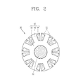
- FIG. 2 is a sectional view of a rotor of FIG. 1 .
- the electric motor includes a stator 20, and a rotor 30 disposed so as to be rotatable with respect to the stator 20.
- a frame or a case 10 (hereinafter, will be expressed as a case 10) is provided outside the stator 20.
- a bearing 12 for rotatably supporting the rotor 30 is provided at the case 10.
- the stator 20 includes a stator core 22, and a stator coil 24 wound on the stator core 22.
- the rotor 30 includes a shaft 31, a rotor core 41 coupled to the shaft 31, and a rotor coil 51 wound on the rotor core 41.
- the rotor core 41 includes a hub 43 to which the shaft 31 is coupled, and a plurality of poles 45 protruding from the hub 43 in a radial direction.
- the poles 45 are spaced from each other at constant intervals in a circumferential direction.
- a slot 44 is formed between the two neighboring poles 45.
- the rotor coil 51 is wound on each pole 45 a plurality of times.
- a power supply unit 35 for supplying power to the rotor coil 51 is provided at the shaft 31.
- the power supply unit 35 includes commutators or slip rings 36 coupled to the shaft 31, and brushes 37 contacting the commutators or the slip rings 36 so as to be conducted.
- the conventional electric motor has the following problems.
- the rotor coil 51 does not smoothly emit heat due to a relatively small contact area with air. This may cause temperature increase of the rotor coil 51. If the rotor coil 51 has drastic temperature increase, the electric motor may have a lowered output.
- an aspect of the detailed description is to provide an electric motor capable of preventing a short-circuit of a rotor coil occurring from a centrifugal force when a rotor rotates.
- Another aspect of the detailed description is to provide an electric motor capable of preventing a short-circuit of a rotor coil, and capable of enhancing a cooling performance of the rotor coil.
- an electric motor comprising: a stator; and a rotor disposed so as to be rotatable with respect to the stator, wherein the rotor includes a rotor core having a plurality of poles and slots; a shaft coupled to a central portion of the rotor core; a rotor coil wound on the rotor core; and a coil supporting member provided at the rotor core, and configured to support the rotor coil such that the rotor coil is prevented from being separated from the rotor core in a radial direction when the rotor rotates.
- the coil supporting members may be coupled to the rotor core before the rotor coil is wound on the rotor core. And, the rotor coil may be simultaneously wound on the rotor core and the coil supporting members.
- the coil supporting members may include a hub coupled to the shaft, a plurality of spokes extending from the hub in a radial direction, and supporting portions protruding from the ends of the spokes in an axial direction, and configured to support the coil ends of the rotor coil.
- the coil supporting members may be coupled to the rotor core after the rotor coil is wound on the rotor core.
- Each pole may be provided with a pole shoe extending in a circumferential direction.
- the coil supporting members may include coil end accommodation portions for accommodating the coil ends of the rotor coil, and supporting plates disposed between the pole shoes.
- the coil supporting members may be coupled to the rotor core in an axial direction of the rotor core.
- the coil supporting members may be provided with an outer circumference having the same diameter as that of an outer circumference of the rotor core. And, the coil end accommodation portions and the supporting plates may be integrally formed with each other, or may be configured so as to be insertion-coupled.
- the coil supporting members may further include reinforcing members disposed on the circumferences of the coil supporting members, and configured to reinforce the supporting portions.
- the reinforcing members may have a fiber or wire-shape, and may be wound on the supporting portions a plurality of times.
- the reinforcing members may have a ring shape, and may be insulation-coated. And, the reinforcing member may be configured such that an inner surface thereof contacts an outer surface of the supporting portions.
- a plurality of insertion protrusions inserted into a space between the supporting portions may be provided at the reinforcing members.
- Each pole of the rotor core may be provided with a pole shoe extending in a circumferential direction, and the pole shoe of the rotor core may have a thickness smaller than that of the supporting portion in a radial direction.
- a spacer having a thickness corresponding to the difference between the two thicknesses of the supporting portion and the pole shoe, may be provided at an inner side of the pole shoe of the rotor core.
- the coil supporting members may be formed of a synthetic resin member, and reinforcing members may be insert injection-molded thereinto.
- the reinforcing members may be formed as a non-magnetic metallic member.
- the coil supporting members may be formed of a material having a higher heat transfer performance than the rotor core.
- the coil supporting member may include a body configured as a non-magnetic metallic member, and a coating layer formed by coating an insulating member on the surface of the body.
- the coil supporting member may be formed of a non-magnetic metallic member, and the surface thereof may be coated with an insulating member.
- the coil supporting member may include a first coil supporting member disposed at one end of the rotor core, and having the coil end accommodation portions and the supporting plates integrally formed with each other; and a second coil supporting member disposed at another rend of the rotor core, and having the coil end accommodation portions, and insertion portions for inserting the ends of the supporting plates.
- the rotor coil may be provided with a plurality of coil portions wound on the circumference of each pole.
- the coil supporting members may be coupled to two ends of the rotor core in an axial direction, such that coil ends are inserted into the coil end accommodation portions, and such that the supporting plate is inserted into a space between the coil portions.
- the reinforcing members may be configured such that the outer surfaces thereof are insulation-coated by an insulating member.
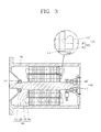
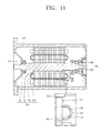
- an electric motor includes a stator 120, and a rotor 140 disposed so as to be rotatable with respect to the stator 120.
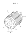
- the rotor 140 includes a rotor core 151 having a plurality of poles 155 and slots 159, a shaft 141 coupled to a central portion of the rotor core 151, a rotor coil 160 wound on the rotor core 151, and coil supporting members 180 provided at the rotor core 151, and configured to support the rotor coil 160 such that the rotor coil 160 is prevented from being separated from the rotor core 151 in a radial direction when the rotor 140 rotates.
- a case 110 may be provided at the outer periphery of the stator 120.
- the case 110 may be formed to correspond to the shape of the stator 120 so that the stator 120 can be accommodated therein.
- a bearing 112 for rotatably supporting the shaft 141 may be provided at the case 110.
- the bearing 112 may be provided at two sides of the case 110, respectively.
- the stator 120 may include a stator core 121, and a stator coil 131 wound on the stator core 121.
- the stator core 121 may be provided with a plurality of slots 125 and teeth 126.
- the stator coil 131 may be configured to be wound on the plurality of slots 125.
- a rotor accommodating space 124 for rotatably accommodating the rotor 140 may be provided at a central region of the stator core 121.
- the rotor 140 may includes a rotor core 151 having a plurality of poles 155 and slots 159, a shaft 141 coupled to a central portion of the rotor core 151, a rotor coil 160 wound on the slots 159 of the rotor core 151, and coil supporting members 180 provided at the rotor core 151, and configured to support the rotor coil 160 so that the rotor coil 160 cannot be separated from the rotor core 151 in a radial direction when the rotor 140 rotates.
- Two sides of the shaft 141 may be rotatably supported by the bearing 112.
- a power supply unit 145 for supplying power to the rotor coil 160 may be provided at the shaft 141.
- the power supply unit 145 may include, for example, commutators or slip rings 146 (hereinafter, will be expressed as 'slip rings') coupled to the shaft 141, and brushes 147 contacting the slip rings 146 so as to be conducted.
- commutators or slip rings 146 hereinafter, will be expressed as 'slip rings'
- the rotor core 151 may include, for example, a plurality of poles 155 spaced from each other at the same intervals, and a plurality of slots 159 disposed between the poles 155.
- the rotor core 151 may include a hub 152, a plurality of poles 155 protruding on the circumference of the hub 152 in a radial direction, and spaced from each other at the same intervals, and a plurality of slots 159 disposed between the poles 155.
- a shaft hole 153 for inserting the shaft 141 may be penetratingly-formed at the hub 152.
- Protrusions 165 see Fig. 5 protruding in a radial direction and protrusion accommodation portions (not shown) for accommodating the protrusions 165 and restricting the protrusions 165 in a rotation direction, may be provided at contact regions between the hub 152 and the shaft 141. Under such configuration, slip occurring between the shaft 141 and the hub 152 can be prevented when the rotor 140 rotates.
- the protrusions 165 protrude in a radial direction from an inner diameter of the shaft hole 153 of the hub 152.
- the protrusion accommodation portions may be concaved from an outer surface of the shaft 141 by a predetermined depth in a radial direction, so that the protrusions 165 can be accommodated therein.
- a pole shoe 156 extending in a circumferential direction may be provided at the end of each pole 155.
- Each pole shoe 156 may extend to two sides from the center of the pole 155.
- Each pole shoe 156 may be formed so that the thickness (in a radial direction) thereof can be gradually decreased towards the two sides.
- an outer surface 157b of each pole shoe 156 may be formed in an arc shape, and an inner surface 157a thereof may be formed in a straight line shape.
- the rotor coil 160 may be provided with a plurality of coil portions 162 wound on the circumference of each pole 155.
- Each coil portion 162 may be provided with coil ends 163 protruding from two ends of the rotor core 151 in an axial direction.
- Each coil portion 162 may be serially connected to each other.
- Each coil portion 162 may be wound on each pole 155 in a different direction so that different poles (N and S) can be formed.
- the coil portions 162 may be wound around the pole shoes 156 so that the interval therebetween can be increased.
- Coil supporting members 180 may be provided at two ends of the rotor core 151.
- the coil supporting members 180 may be coupled to the rotor core 151 before the rotor coil 160 is wound on the rotor core 151. That is, the coil supporting members 180 are coupled to two ends of the rotor core 151, and then the rotor coil 160 may be wound on the rotor core 151 and the coil supporting members 180.
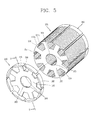
- the coil supporting members 180 may include a hub 182 coupled to the shaft 141, a plurality of spokes 185 extending from the hub 182 in a radial direction, and supporting portions 187 protruding from the ends of the spokes 185 in an axial direction, and configured to support the coil ends 163 of the rotor coil 160.
- the supporting portions 187 are disposed outside the coil ends 163 in a radial direction of the rotor core 151, and contact the outer circumference (outer surface) of the coil ends 163. Under such configuration, the supporting portions 187 can support the coil ends 163 so as to be maintained at the initial position, against a centrifugal force applied in a radial direction when the rotor 140 rotates.
- the coil supporting members 180 may be formed of a material having a higher heat transfer performance than the rotor core 151 (e.g., aluminum). Accordingly, since heat of the rotor coil 160 is transferred to the coil supporting members 180, cooling of the rotor coil 160 can be accelerated.
- the coil supporting members 180 may be configured as a non-magnetic metallic member (e.g., aluminum, stainless steel, etc.). Accordingly, leakage of a magnetic flux due to the coil supporting members 180 can be prevented.
- a non-magnetic metallic member e.g., aluminum, stainless steel, etc.
- the coil supporting members 180 may include a body 181a configured as a non-magnetic metallic member, and a coating layer 181b formed by coating an insulating member (electric insulating member) on the outer surface of the body 181a.
- the coil supporting member 185 may include a body 186a formed of a synthetic resin member, and reinforcing members 186b insert injection-molded in the body 186a.
- the reinforcing members 186b may be formed as metallic members, for instance.
- a shaft hole 183 for inserting the shaft 141 may be penetratingly-formed at the hub 182 of the coil supporting members 180.
- Protrusions 184 protruding in a radial direction and protrusion accommodation portions (not shown) for accommodating the protrusions 184 may be provided at contact regions between the hub 182 and the shaft 141. Under such configuration, slip occurring between the shaft 141 and the hub 182 when the rotor 140 rotates, can be prevented.
- Reinforcing members 190 may be provided at the outer peripheries of the coil supporting members 180. Under such configuration, when the rotor 140 rotates, the coil supporting members 180 and the rotor coil 160 can be more stably supported.
- the reinforcing members 190 may be formed in a ring shape by winding fiber or wire-shaped reinforcing members on the outer surfaces of the coil supporting members 180 (outer surfaces of the supporting members) a plurality of times.
- the reinforcing members 190 may be formed by winding glass fibers 192 on the outer surfaces of the coil supporting members 180 a plurality of times. As the coil supporting members 180 are supported by the glass fibers 192 having a high specific strength, the coil supporting members 180 and the rotor coil 160 can be effectively supported without increasing the weight of the reinforcing members 190.
- the coil supporting members 180 are provided at two ends of the rotor core 151, and the rotor coil 160 is wound on the rotor core 151 and the coil supporting members 180.
- the reinforcing members 190 may be provided on the circumference of the coil supporting members 180.
- the coil portions 162 are formed to alternately have different poles (N and S). And, each coil portion interacts (attracts and repulses) with a magnetic field formed by the stator coil 131. As a result, the rotor 140 can rotate about the shaft 141.
- the coil supporting members 180 prevent the respective coil portions 162 of the rotor coil 160 from moving in a radial direction by a centrifugal force. Accordingly, the occurrence of a short-circuit of the rotor coil 160 can be prevented.
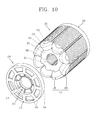
- FIGS. 9 and 10 Another embodiment of the present invention will be explained with reference to FIGS. 9 and 10 .
- the electric motor may include a stator 120, and a rotor 140 disposed so as to be rotatable with respect to the stator 120.
- the rotor 140 may include a rotor core 151 having a plurality of poles 155 and slots 159, a shaft 141 coupled to a central portion of the rotor core 151, a rotor coil 160 wound on the rotor core 151, and coil supporting members 210 provided at the rotor core 151, and configured to support the rotor coil 160 so that the rotor coil 160 cannot be separated from the rotor core 151 in a radial direction when the rotor 140 rotates.
- a case 110 may be provided at the outer periphery of the stator 120.
- a bearing 112 for rotatably supporting the rotor 140 may be provided at the case 110.
- a power supply unit 145 having slip rings 146 and brushes 147, and configured to supply power to the rotor coil 160 may be provided at the shaft 141.
- the rotor core 151 may be provided with a plurality of poles 155 and slots 159.
- the coil supporting members 210 may be wound on the rotor coil 160, and then may be coupled to the rotor core 151.
- the coil supporting members 210 may include a hub 212 coupled to the shaft 141, and coil end coupling portions 215 disposed on the circumference of the hub 212 and coupled to the coil ends 163.
- a shaft hole 213 for inserting the shaft 141 may be penetratingly-formed at the hub 212.
- the coil end coupling portion 215 may be provided with an outer wall portion 216 disposed to contact the outer surface of each coil end 163 in a radial direction of the rotor core 151. Under such configuration, the coil ends 163 can be supported against a centrifugal force applied to the coil ends 163 when the rotor 140 rotates.
- the outer wall portion 216 may be formed in a ring shape.
- the coil end coupling portions 215 may have through holes 218 through which part of the coil ends 163 can be exposed to the outside.
- the coil supporting members 210 may be formed of a non-magnetic metallic member, and the surfaces thereof may be coated with an insulating member.
- the coil supporting members 210 may be coupled to two ends of the rotor core 151.
- the coil ends 163 of the rotor coil 160 are supported against a centrifugal force by the outer wall portions 216 of the coil supporting members 210. Accordingly, the occurrence of a short-circuit of the rotor coil 160 can be prevented.
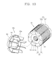
- the electric motor includes a stator 120, and a rotor 140 disposed so as to be rotatable with respect to the stator 120.
- the rotor 140 includes a rotor core 151 having a plurality of poles 155 and slots 159, a shaft 141 coupled to a central portion of the rotor core 151, a rotor coil 160 wound on the rotor core 151, and a coil supporting member 230a provided at the rotor core 151, and configured to support the rotor coil 160 so that the rotor coil 160 cannot be separated from the rotor core 151 in a radial direction when the rotor 140 rotates.
- a case 110 may be provided at the outer periphery of the stator 120.
- Coil supporting members 230a may be provided at two ends of the rotor core 151.
- the coil supporting members 230a may be coupled to the rotor core 151 after the rotor coil 160 is wound on the rotor core 151.
- the coil supporting members 230a may be coupled to two sides of the rotor core 151 in an axial direction of the rotor 140.
- the coil supporting member 230a may include coil end accommodation portions 232 for accommodating the coil ends 163 of the rotor coil 160, and supporting plates 235a disposed between the pole shoes 156.
- the coil end accommodation portions 232 may be formed in a shape (e.g., arc shape) corresponding to the shape of the coil ends 163.
- Each coil end accommodation portion 232 may be provided with an accommodation space 233 therein, the accommodation space for accommodating each coil end 163.
- Each coil end accommodation portion 232 may be formed so that the rotor core side thereof can be open.
- the coil supporting member 230a may have the same outer diameter as the rotor core 151.
- the coil supporting member 230a may be provided with a plurality of supporting plates 235a, each supporting plate 235a inserted into a space between the coil portions 162 wound on the poles 155.
- each supporting plate 235a may be configured to be simultaneously connected to two neighboring coil end accommodation portions 232. Under such configuration, separation of each coil end accommodation portion 232 from the rotor core 151 due to a centrifugal force when the rotor 140 rotates, can be prevented. Further, gaps between the coil portions 162 are blocked by the supporting plates 235a. This can prevent outward movements of the coil portions 162 wound on the poles 155 by a centrifugal force in a radial direction when the rotor 140 rotates.
- Each supporting plate 235a may be disposed in a radial direction of the rotor core 151.
- Edges inside each supporting plate 235a may contact the rotor core 151, respectively.
- the supporting plate 235a may be formed to have a length shorter than that of the rotor core 151 in an axial direction.
- the supporting plate 235a may have a length corresponding to the half of a length of the rotor core 151 in an axial direction.
- the coil supporting member 230b may include a first coil supporting member 241 disposed at one end of the rotor core 151, and a second coil supporting member 251 disposed at another rend of the rotor core 151.
- the first coil supporting member 241 includes coil end accommodation portions 232 for accommodating the coil ends 163 of the rotor coil 160, and supporting plates 235b disposed between the pole shoes 156.
- the second coil supporting member 251 includes coil end accommodation portions 232, and insertion portions 253 for inserting another ends of the supporting plates 235b.
- the supporting plates 235b of the first coil supporting member 241 may have a length long enough to protrude towards another end of the rotor core 151 by passing through the rotor core 151.
- a plurality of insertion portions 253 for inserting the ends of the supporting plates 235b having protruded through the rotor core 151, may be formed at the second coil supporting member 251, respectively.
- the insertion portions 253 may be configured as grooves and/or holes.
- the second coil supporting member 251 may be integrally coupled to the supporting plates 235b of the first coil supporting member 241, thereby supporting the coil ends 163 accommodated therein against a centrifugal force.
- the coil supporting members 230a and 230b may be formed of a material having a higher heat transfer performance than the rotor core 151.
- the coil supporting members 230a and 230b may be formed of aluminum. Under such configuration, heat of the rotor coil 160 is transferred to two sides of the rotor core 151 through the coil supporting members 230a and 230b (supporting plates). As a result, the temperature of the rotor coil 160 can be prevented from excessively increasing.
- the aforementioned fiber or wire-shaped reinforcing members 190 may be provided on the circumferences of the coil supporting members 230a and 230b.
- the coil supporting members 230a and 230b may be coupled to two ends of the rotor core 151, respectively.
- the coil ends 163 of the rotor coil 160 may be accommodated in the coil end accommodation portions 232, and each supporting plate 235a may be inserted into a space between the two neighboring coil portions 162.
- the coil ends 163 of the rotor coil 160 are supported by the coil end accommodation portions 232 against a centrifugal force.
- the rotor coil 160 can be prevented from being separated from the rotor core 151 or from moving in a radial direction, and thus a short-circuit of the rotor coil 160 can be prevented.
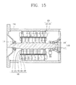
- FIGS. 15 to 18 yet still another embodiment of the present invention will be explained with reference to FIGS. 15 to 18 .
- the electric motor includes a stator 120, and a rotor 140 disposed so as to be rotatable with respect to the stator 120.
- the rotor 140 includes a rotor core 151 having a plurality of poles 155 and slots 159, a shaft 141 coupled to a central portion of the rotor core 151, a rotor coil 160 wound on the rotor core 151, and coil supporting members 260 provided at the rotor core 151, and configured to support the rotor coil 160 so that the rotor coil 160 can be prevented from being separated from the rotor core 151 in a radial direction when the rotor 140 rotates.
- a case 110 may be provided at the outer periphery of the stator 120.
- a plurality of poles 155 and slots 159 may be provided at the rotor core 151.
- the rotor coil 160 may be provided with a plurality of coil portions 162 wound on the poles 155.
- a pole shoe 156 may be provided at the end of each pole 155 of the rotor core 151.
- Pole shoes 156 may be formed to have a preset interval (s1) therebetween.
- Coil supporting members 260 may be provided at two ends of the rotor core 151 in an axial direction.
- the coil supporting members 260 may be configured as non-magnetic metallic members (e.g., aluminum, stainless steel, etc.).
- the coil supporting members 260 may be insulation-coated with an insulating member.
- the coil supporting members 180 may include a hub 262 coupled to the shaft 141, a plurality of spokes 265 extending from the hub 262 in a radial direction, and supporting portions 267 protruding from the ends of the spokes 265 in an axial direction, and configured to support the coil ends 163 of the rotor coil 160.
- a shaft hole 263 for inserting the shaft 141 may be penetratingly-formed at the hub 262.
- Protrusions 268 protruding in a radial direction may be provided at the shaft hole 262. As the protrusions 268 are inserted into protrusion accommodation portions (not shown) formed on the outer surface of the shaft 141, slip occurring when the rotor rotates can be prevented.
- the spokes 265 may be formed to correspond to the poles of the rotor core 151.
- each spoke 265 may be formed to have the same interval and width as each pole 155.
- Supporting portions 267 for supporting the coil ends 163 of the rotor coil 160 may be provided at the ends of the spokes 265.
- Each supporting portion 267 may protrude from the end of each spoke 265 in an axial direction.
- Each supporting portion 267 may have the same length as each pole shoe 156 in a circumferential direction.
- the supporting portions 267 may have a preset interval (s2) therebetween.
- the interval (s2) between the supporting portions 267 may be the same as the interval (s1) between the pole shoes 156.
- Guide portions 271 may be formed at two ends of each supporting portion 267 in a circumferential direction.
- Each guide portion 271 may be formed in a curved shape so that its length in a circumferential direction can be gradually decreased in a protruding direction of each supporting portion 267. Under such configuration, the interval (s2) between the supporting portions 267 can be gradually increased in a protruding direction of the supporting portions 267.
- the guide portion 271 may facilitate coupling of reinforcing members 280 to be later explained with the supporting portions 267.
- Reinforcing members 280 may be coupled to the coil supporting members 260. This may allow the rotor coil 160 to be more stably supported.
- the reinforcing members 280 may have a ring shape.
- the reinforcing members 280 may simultaneously contact the outer surfaces of the supporting portions 267.
- Reinforcing member coupling portions 273 for coupling the reinforcing members 280 may be formed on the outer surfaces of the supporting portions 267.
- the reinforcing member coupling portions 273 may have steps in a shape that the outer surface of the supporting portions 267 are cut to be decreased in a radial direction, in correspondence to the thickness of the reinforcing members 280.
- the reinforcing members 280 may be implemented as steel plates having a high intensity and formed in a ring shape.
- the reinforcing members 280 may be insulation-coated with an insulating member.
- the reinforcing member 280 may be provided with a plurality of insertion protrusions 282 inserted into the interval (s2) between the supporting portions 267 of the coil supporting member 260.
- Each insertion protrusion 282 may be configured to have a width (s3) corresponding to the interval (s2) between the supporting portions 267.
- the pole shoe 156 and the supporting portion 267 may have thicknesses different from each other.
- the pole shoe 156 may have a relatively small thickness (t1) for an enhanced output.
- the supporting portions 267 may have a relatively great thickness (t2) so as to more stably support the coil ends 163 with an increased intensity (supporting intensity).
- a spacer 290 may be provided at an inner side of each pole shoe 156.
- the spacer 290 may be configured to have a thickness (t3) corresponding to the difference between the thickness (t1) of the pole shoe 156 and the thickness (t2) of the supporting portion 267.
- the inner surface of the spacer 290 and the inner surface of the supporting portion 267 can be disposed on the same plane.
- the rotor coil 160 can be easily wound on the rotor core, and the rotor coil 160 having been wound on the rotor core can be stably supported.
- the spacer 290 may be formed to have a length corresponding to a length of the rotor core 151 in an axial direction (or laminated thickness). Under such configuration, two ends of the spacer 290 can be coupled to the coil supporting members 260, and then may contact the inner surfaces of the coil supporting members 260, respectively.
- each spacer 290 may be configured to be adhered to the inner surface 157b of each pole shoe 156.
- each spacer 290 may be provided on the inner surface 157b of each pole shoe 156 of the rotor core 151.
- the coil supporting members 260 may be provided at two ends of the rotor core 151, and the rotor coil 160 may be wound on the rotor core 151 along the inner surfaces of the spacer 290 and the supporting portions 267, respectively.
- the reinforcing members 280 may be coupled to the coil supporting members 260.
- the insertion protrusions 282 of the reinforcing member 280 are guided by the guide portions 271 formed at two ends of each supporting portion 267, so that the reinforcing members 280 can be easily inserted into the coil supporting members 260.
- stator coil 131 and the rotor coil 160 power is supplied to the stator coil 131 and the rotor coil 160, respectively.
- the rotor 140 rotates about the shaft 141.
- the coil supporting members 260 prevents the coil portions 162 of the rotor coil 160 from moving in a radial direction by a centrifugal force when the rotor 140 rotates. Accordingly, the occurrence of a short-circuit of the rotor coil 160 can be prevented.
- the electric motor according to the present invention may have the following advantages.
- the coil supporting members for supporting the rotor coil are provided outside the rotor coil in a radial direction. Accordingly, a short-circuit of the rotor coil due to a centrifugal force when the rotor rotates, can be prevented.
- the rotor coil can be wound on the coil supporting members when being wound on the rotor core.
- the rotor coil can stably maintain the initially-wound position. This can prevent the rotor coil from being transformed, and/or can prevent a short-circuit of the rotor coil and can prolong the lifespan of the rotor coil.
- the coil supporting members are coupled to the rotor core after the rotor coil is wound on the rotor core. This can facilitate a winding operation of the rotor coil.
- the supporting plates are provided at the coil supporting members so as to be disposed between the coil portions. This can prevent the rotor coil from moving or being transformed in a radial direction.
- the rotor coil can be more stably supported.
- the coil supporting members are formed of a material having a higher heat transfer performance than the rotor core, temperature increase of the rotor coil can be prevented.
- each pole shoe of the rotor core is configured to have a thickness smaller than that of each supporting portion of the coil supporting member, and a spacer is configured to have a thickness corresponding to the difference between the two thicknesses. Accordingly, the thickness of the pole shoe can be reduced. As a result, an output of the electric motor can be enhanced, a winding operation of the rotor coil can be easily performed, and the rotor coil can be stably supported.
Landscapes
- Engineering & Computer Science (AREA)
- Power Engineering (AREA)
- Insulation, Fastening Of Motor, Generator Windings (AREA)
- Iron Core Of Rotating Electric Machines (AREA)
Applications Claiming Priority (1)
| Application Number | Priority Date | Filing Date | Title |
|---|---|---|---|
| KR1020120109668A KR101364028B1 (ko) | 2012-10-02 | 2012-10-02 | 전동기 |
Publications (3)
| Publication Number | Publication Date |
|---|---|
| EP2717435A2 true EP2717435A2 (de) | 2014-04-09 |
| EP2717435A3 EP2717435A3 (de) | 2017-11-22 |
| EP2717435B1 EP2717435B1 (de) | 2020-07-01 |
Family
ID=47458765
Family Applications (1)
| Application Number | Title | Priority Date | Filing Date |
|---|---|---|---|
| EP12199465.1A Active EP2717435B1 (de) | 2012-10-02 | 2012-12-27 | Elektromotor |
Country Status (4)
| Country | Link |
|---|---|
| US (1) | US9166454B2 (de) |
| EP (1) | EP2717435B1 (de) |
| KR (1) | KR101364028B1 (de) |
| CN (1) | CN103715792B (de) |
Cited By (4)
| Publication number | Priority date | Publication date | Assignee | Title |
|---|---|---|---|---|
| DE102020127930A1 (de) | 2020-10-23 | 2022-04-28 | Valeo Siemens Eautomotive Germany Gmbh | Rotor für eine elektrische Maschine, elektrische Maschine zum Antreiben eines Fahrzeugs und Fahrzeug |
| DE102021131729A1 (de) | 2021-12-02 | 2023-06-07 | Bayerische Motoren Werke Aktiengesellschaft | Rotor mit einer Stützvorrichtung, elektrische Maschine mit einem Rotor und Kraftfahrzeug mit einer elektrischen Maschine |
| EP4199315A1 (de) * | 2021-12-14 | 2023-06-21 | Valeo eAutomotive Germany GmbH | Rotor für eine elektrische drehmaschine |
| WO2024105139A1 (de) * | 2022-11-18 | 2024-05-23 | Vitesco Technologies Germany Gmbh | Rotor, elektrische maschine und kraftfahrzeug |
Families Citing this family (24)
| Publication number | Priority date | Publication date | Assignee | Title |
|---|---|---|---|---|
| KR20140003674A (ko) * | 2012-06-22 | 2014-01-10 | 엘지이노텍 주식회사 | 모터 |
| DE102014206356A1 (de) | 2014-04-03 | 2015-10-08 | Bayerische Motoren Werke Aktiengesellschaft | Verbesserte Sternscheibe für eine elektrische Maschine |
| KR102195806B1 (ko) * | 2014-04-29 | 2020-12-28 | 엘지이노텍 주식회사 | 로터 조립체 및 이를 포함하는 모터 |
| KR101683494B1 (ko) * | 2014-12-03 | 2016-12-07 | 현대자동차 주식회사 | 계자권선형 구동모터의 회전자 |
| KR101664047B1 (ko) * | 2014-12-03 | 2016-10-10 | 현대자동차 주식회사 | 계자권선형 구동모터의 회전자 |
| KR102318229B1 (ko) * | 2014-12-10 | 2021-10-27 | 엘지이노텍 주식회사 | 로터 조립체 및 이를 포함하는 모터 |
| KR102380924B1 (ko) * | 2014-12-24 | 2022-04-01 | 엘지이노텍 주식회사 | 로터 조립체 및 이를 포함하는 모터 |
| KR102408250B1 (ko) * | 2015-07-21 | 2022-06-13 | 엘지이노텍 주식회사 | 로터 및 이를 포함하는 모터 |
| DE102015219685A1 (de) * | 2015-10-12 | 2017-04-13 | Robert Bosch Gmbh | Rotor, elektrische Maschine beinhaltend einen solchen Rotor, sowie Verfahren zum Herstellen eines Rotors |
| KR101798919B1 (ko) * | 2016-01-25 | 2017-11-17 | 엘지전자 주식회사 | 회전전기기계 |
| KR101855763B1 (ko) * | 2016-06-03 | 2018-05-09 | 현대자동차 주식회사 | 계자권선형 구동모터 |
| DE102017216074A1 (de) | 2016-10-14 | 2018-04-19 | Robert Bosch Gmbh | Elektromotor mit einem Klemmelement |
| US11038389B2 (en) * | 2018-08-24 | 2021-06-15 | Hamilton Sundstrand Corporation | Rotor end plate |
| DE102018128521A1 (de) * | 2018-11-14 | 2020-05-14 | Bayerische Motoren Werke Aktiengesellschaft | Stützeinrichtung für einen Rotor einer fremderregten Innenläufer-Synchronmaschine, Rotor, fremderregte Innenläufer-Synchronmaschine sowie Kraftfahrzeug |
| DE102019218603A1 (de) * | 2019-11-29 | 2021-06-02 | Robert Bosch Gmbh | Rotor für eine elektrische Maschine, elektrische Maschine sowie Verfahren |
| JP7414666B2 (ja) * | 2020-08-19 | 2024-01-16 | 株式会社三井ハイテック | コア部製造装置 |
| EP3989406A1 (de) * | 2020-10-26 | 2022-04-27 | Valeo Siemens eAutomotive Germany GmbH | Rotor und verfahren zum imprägnieren der wicklungen |
| US11569703B2 (en) * | 2021-01-04 | 2023-01-31 | Hamilton Sundstrand Corporation | Integrated wedge cooling distribution plate and end turn support |
| DE102021124234A1 (de) * | 2021-09-20 | 2023-03-23 | Bayerische Motoren Werke Aktiengesellschaft | Stützeinrichtung für einen Rotor mit Rovingwicklung |
| DE102021211102A1 (de) | 2021-10-01 | 2023-04-06 | Mahle International Gmbh | Elektrische Radialflussmaschine |
| FR3128329A1 (fr) * | 2021-10-18 | 2023-04-21 | Novares France | Rotor bobiné pour moteur électrique agencé pour faciliter son assemblage |
| EP4203266A1 (de) * | 2021-12-23 | 2023-06-28 | Valeo eAutomotive Germany GmbH | Rotor für eine rotierende elektrische maschine mit einer sperre zum schutz der spulenenden des rotors |
| DE102022111413A1 (de) * | 2022-05-09 | 2023-11-09 | Bayerische Motoren Werke Aktiengesellschaft | Rotor für eine elektrische Traktionsmaschine eines Kraftfahrzeugs sowie elektrische Traktionsmaschine |
| KR102666492B1 (ko) * | 2023-08-04 | 2024-05-14 | 코오롱글로텍주식회사 | 구동모터 회전자 및 구동모터 회전자 물성 강화 방법 |
Family Cites Families (20)
| Publication number | Priority date | Publication date | Assignee | Title |
|---|---|---|---|---|
| US3558950A (en) * | 1968-07-11 | 1971-01-26 | Reliance Electric & Eng Co | Coil end support |
| FR2050536A5 (de) * | 1969-06-17 | 1971-04-02 | Cem Comp Electro Mec | |
| US4091301A (en) * | 1974-07-08 | 1978-05-23 | Bbc Brown Boveri & Company Limited | Rotor end-winding support for high-speed electrical machine such as a turbo-generator |
| US4275324A (en) * | 1979-08-31 | 1981-06-23 | Westinghouse Electric Corp. | Dynamoelectric machine having shielded retaining rings |
| DE4021599A1 (de) * | 1990-07-06 | 1992-01-09 | Vdo Schindling | Buerstenloser gleichstrommotor |
| KR200166027Y1 (ko) * | 1997-04-10 | 2000-01-15 | 에릭 발리베 | 시동전동기 회전자 코일 고정링 |
| SE523440C2 (sv) * | 1999-02-15 | 2004-04-20 | Abb Ab | Roterande elektrisk likströmsmaskin samt rotor och rotorhärvstöd för en sådan maskin |
| KR200206559Y1 (ko) | 2000-07-01 | 2000-12-01 | 주식회사캄코 | 모터용 코일 이탈방지 구조 |
| FR2819350B1 (fr) * | 2001-01-05 | 2003-04-11 | Valeo Equip Electr Moteur | Machine tournante perfectionnee pour vehicules automobiles |
| US6727634B2 (en) * | 2001-08-30 | 2004-04-27 | Honeywell International, Inc. | System and method for end turn retention on a high speed generator rotor |
| US6864617B1 (en) * | 2003-10-02 | 2005-03-08 | General Electric Company | Retaining system for a rotor of a dynamoelectric machine |
| US7061154B2 (en) * | 2004-03-24 | 2006-06-13 | Honeywell International, Inc. | Lightweight wedge design for high speed generators |
| US20060071569A1 (en) * | 2004-10-04 | 2006-04-06 | Stewart William P | Stator end caps and methods for positioning the lead and exit ends of the stator windings |
| US7786630B2 (en) * | 2007-04-16 | 2010-08-31 | Honeywell International Inc. | Spray cooled V-wedge for aerospace generator |
| KR100768248B1 (ko) * | 2007-07-12 | 2007-10-18 | 티에스파워(주) | 발전기 |
| JP5307448B2 (ja) * | 2008-05-20 | 2013-10-02 | 日立三菱水力株式会社 | 回転電機 |
| US8084902B2 (en) * | 2009-05-06 | 2011-12-27 | Hamilton Sundstrand Corporation | End plates for high speed generator applications |
| US8339011B2 (en) | 2009-12-07 | 2012-12-25 | Hamilton Sundstrand Corporation | Rotor assembly wire support |
| WO2012007920A1 (en) * | 2010-07-14 | 2012-01-19 | Brusa Elektronik Ag | Rotor for electrical machine, in particular for a synchronous motor |
| CN202260706U (zh) | 2011-10-11 | 2012-05-30 | 重庆神驰机电有限公司 | 电机转子骨架 |
-
2012
- 2012-10-02 KR KR1020120109668A patent/KR101364028B1/ko active IP Right Grant
- 2012-12-11 US US13/711,302 patent/US9166454B2/en active Active
- 2012-12-27 EP EP12199465.1A patent/EP2717435B1/de active Active
-
2013
- 2013-03-27 CN CN201310101247.8A patent/CN103715792B/zh active Active
Non-Patent Citations (1)
| Title |
|---|
| None |
Cited By (5)
| Publication number | Priority date | Publication date | Assignee | Title |
|---|---|---|---|---|
| DE102020127930A1 (de) | 2020-10-23 | 2022-04-28 | Valeo Siemens Eautomotive Germany Gmbh | Rotor für eine elektrische Maschine, elektrische Maschine zum Antreiben eines Fahrzeugs und Fahrzeug |
| US11695304B2 (en) | 2020-10-23 | 2023-07-04 | Valeo Siemens Eautomotive Germany Gmbh | Rotor for an electrical machine, electrical machine for driving a vehicle, and vehicle |
| DE102021131729A1 (de) | 2021-12-02 | 2023-06-07 | Bayerische Motoren Werke Aktiengesellschaft | Rotor mit einer Stützvorrichtung, elektrische Maschine mit einem Rotor und Kraftfahrzeug mit einer elektrischen Maschine |
| EP4199315A1 (de) * | 2021-12-14 | 2023-06-21 | Valeo eAutomotive Germany GmbH | Rotor für eine elektrische drehmaschine |
| WO2024105139A1 (de) * | 2022-11-18 | 2024-05-23 | Vitesco Technologies Germany Gmbh | Rotor, elektrische maschine und kraftfahrzeug |
Also Published As
| Publication number | Publication date |
|---|---|
| CN103715792A (zh) | 2014-04-09 |
| EP2717435A3 (de) | 2017-11-22 |
| EP2717435B1 (de) | 2020-07-01 |
| US20140091670A1 (en) | 2014-04-03 |
| CN103715792B (zh) | 2015-05-27 |
| US9166454B2 (en) | 2015-10-20 |
| KR101364028B1 (ko) | 2014-02-19 |
Similar Documents
| Publication | Publication Date | Title |
|---|---|---|
| EP2717435A2 (de) | Elektromotor | |
| EP2827474B1 (de) | Motor | |
| EP2978103B1 (de) | Rotor | |
| WO2015087445A1 (ja) | 永久磁石埋込型回転電機 | |
| KR101664047B1 (ko) | 계자권선형 구동모터의 회전자 | |
| US20120181880A1 (en) | Electric motor | |
| EP1835601B1 (de) | Hybrid-Induktionsmotor | |
| CN109075653B (zh) | 具有优化的冷却的旋转电机 | |
| JP2018078788A (ja) | モータ及びそのロータ | |
| CN111654129A (zh) | 转子及旋转电机 | |
| JP2018161001A (ja) | Ipmロータおよび回転電機 | |
| EP2744086B1 (de) | Kühlmittelzuführungs- und -auffangvorrichtung und damit ausgestatteter Motor | |
| EP3790170A1 (de) | Rotierende maschine und isolator | |
| CN111934493A (zh) | 旋转电机 | |
| KR20140036339A (ko) | 모터 | |
| US9787153B2 (en) | Outer rotor type dynamo | |
| KR101711583B1 (ko) | 회전자 및 이를 포함하는 모터 | |
| JP2013005531A (ja) | アウターロータ型回転電機 | |
| KR101798331B1 (ko) | 코어레스형 비엘디씨 모터 | |
| JP2010004609A (ja) | モータ | |
| JP6593881B2 (ja) | アキシャルギャップ型回転電機の製造方法 | |
| CN111835111A (zh) | 转子及表面磁铁型旋转电机 | |
| KR20140145996A (ko) | 전기 모터 | |
| CN111989848A (zh) | 同步电机 | |
| KR101398461B1 (ko) | 전동기 |
Legal Events
| Date | Code | Title | Description |
|---|---|---|---|
| PUAI | Public reference made under article 153(3) epc to a published international application that has entered the european phase |
Free format text: ORIGINAL CODE: 0009012 |
|
| 17P | Request for examination filed |
Effective date: 20130125 |
|
| AK | Designated contracting states |
Kind code of ref document: A2 Designated state(s): AL AT BE BG CH CY CZ DE DK EE ES FI FR GB GR HR HU IE IS IT LI LT LU LV MC MK MT NL NO PL PT RO RS SE SI SK SM TR |
|
| AX | Request for extension of the european patent |
Extension state: BA ME |
|
| PUAL | Search report despatched |
Free format text: ORIGINAL CODE: 0009013 |
|
| AK | Designated contracting states |
Kind code of ref document: A3 Designated state(s): AL AT BE BG CH CY CZ DE DK EE ES FI FR GB GR HR HU IE IS IT LI LT LU LV MC MK MT NL NO PL PT RO RS SE SI SK SM TR |
|
| AX | Request for extension of the european patent |
Extension state: BA ME |
|
| RIC1 | Information provided on ipc code assigned before grant |
Ipc: H02K 3/00 20060101ALI20171016BHEP Ipc: H02K 3/46 20060101ALI20171016BHEP Ipc: H02K 3/50 20060101ALI20171016BHEP Ipc: H02K 3/487 20060101AFI20171016BHEP Ipc: H02K 3/52 20060101ALI20171016BHEP |
|
| RBV | Designated contracting states (corrected) |
Designated state(s): AL AT BE BG CH CY CZ DE DK EE ES FI FR GB GR HR HU IE IS IT LI LT LU LV MC MK MT NL NO PL PT RO RS SE SI SK SM TR |
|
| RIC1 | Information provided on ipc code assigned before grant |
Ipc: H02K 3/00 20060101ALI20190829BHEP Ipc: H02K 3/52 20060101ALI20190829BHEP Ipc: H02K 3/487 20060101AFI20190829BHEP Ipc: H02K 3/50 20060101ALI20190829BHEP Ipc: H02K 3/46 20060101ALI20190829BHEP |
|
| GRAP | Despatch of communication of intention to grant a patent |
Free format text: ORIGINAL CODE: EPIDOSNIGR1 |
|
| STAA | Information on the status of an ep patent application or granted ep patent |
Free format text: STATUS: GRANT OF PATENT IS INTENDED |
|
| INTG | Intention to grant announced |
Effective date: 20191009 |
|
| GRAS | Grant fee paid |
Free format text: ORIGINAL CODE: EPIDOSNIGR3 |
|
| GRAJ | Information related to disapproval of communication of intention to grant by the applicant or resumption of examination proceedings by the epo deleted |
Free format text: ORIGINAL CODE: EPIDOSDIGR1 |
|
| GRAL | Information related to payment of fee for publishing/printing deleted |
Free format text: ORIGINAL CODE: EPIDOSDIGR3 |
|
| STAA | Information on the status of an ep patent application or granted ep patent |
Free format text: STATUS: REQUEST FOR EXAMINATION WAS MADE |
|
| INTC | Intention to grant announced (deleted) | ||
| RAP1 | Party data changed (applicant data changed or rights of an application transferred) |
Owner name: LG ELECTRONICS INC. |
|
| GRAJ | Information related to disapproval of communication of intention to grant by the applicant or resumption of examination proceedings by the epo deleted |
Free format text: ORIGINAL CODE: EPIDOSDIGR1 |
|
| GRAP | Despatch of communication of intention to grant a patent |
Free format text: ORIGINAL CODE: EPIDOSNIGR1 |
|
| GRAR | Information related to intention to grant a patent recorded |
Free format text: ORIGINAL CODE: EPIDOSNIGR71 |
|
| STAA | Information on the status of an ep patent application or granted ep patent |
Free format text: STATUS: GRANT OF PATENT IS INTENDED |
|
| GRAA | (expected) grant |
Free format text: ORIGINAL CODE: 0009210 |
|
| STAA | Information on the status of an ep patent application or granted ep patent |
Free format text: STATUS: THE PATENT HAS BEEN GRANTED |
|
| AK | Designated contracting states |
Kind code of ref document: B1 Designated state(s): AL AT BE BG CH CY CZ DE DK EE ES FI FR GB GR HR HU IE IS IT LI LT LU LV MC MK MT NL NO PL PT RO RS SE SI SK SM TR |
|
| INTG | Intention to grant announced |
Effective date: 20200525 |
|
| REG | Reference to a national code |
Ref country code: GB Ref legal event code: FG4D |
|
| REG | Reference to a national code |
Ref country code: AT Ref legal event code: REF Ref document number: 1287097 Country of ref document: AT Kind code of ref document: T Effective date: 20200715 Ref country code: CH Ref legal event code: EP |
|
| REG | Reference to a national code |
Ref country code: IE Ref legal event code: FG4D |
|
| REG | Reference to a national code |
Ref country code: DE Ref legal event code: R096 Ref document number: 602012070998 Country of ref document: DE |
|
| REG | Reference to a national code |
Ref country code: LT Ref legal event code: MG4D |
|
| PG25 | Lapsed in a contracting state [announced via postgrant information from national office to epo] |
Ref country code: BG Free format text: LAPSE BECAUSE OF FAILURE TO SUBMIT A TRANSLATION OF THE DESCRIPTION OR TO PAY THE FEE WITHIN THE PRESCRIBED TIME-LIMIT Effective date: 20201001 |
|
| REG | Reference to a national code |
Ref country code: NL Ref legal event code: MP Effective date: 20200701 |
|
| REG | Reference to a national code |
Ref country code: AT Ref legal event code: MK05 Ref document number: 1287097 Country of ref document: AT Kind code of ref document: T Effective date: 20200701 |
|
| PG25 | Lapsed in a contracting state [announced via postgrant information from national office to epo] |
Ref country code: ES Free format text: LAPSE BECAUSE OF FAILURE TO SUBMIT A TRANSLATION OF THE DESCRIPTION OR TO PAY THE FEE WITHIN THE PRESCRIBED TIME-LIMIT Effective date: 20200701 Ref country code: LT Free format text: LAPSE BECAUSE OF FAILURE TO SUBMIT A TRANSLATION OF THE DESCRIPTION OR TO PAY THE FEE WITHIN THE PRESCRIBED TIME-LIMIT Effective date: 20200701 Ref country code: PT Free format text: LAPSE BECAUSE OF FAILURE TO SUBMIT A TRANSLATION OF THE DESCRIPTION OR TO PAY THE FEE WITHIN THE PRESCRIBED TIME-LIMIT Effective date: 20201102 Ref country code: CZ Free format text: LAPSE BECAUSE OF FAILURE TO SUBMIT A TRANSLATION OF THE DESCRIPTION OR TO PAY THE FEE WITHIN THE PRESCRIBED TIME-LIMIT Effective date: 20200701 Ref country code: GR Free format text: LAPSE BECAUSE OF FAILURE TO SUBMIT A TRANSLATION OF THE DESCRIPTION OR TO PAY THE FEE WITHIN THE PRESCRIBED TIME-LIMIT Effective date: 20201002 Ref country code: NO Free format text: LAPSE BECAUSE OF FAILURE TO SUBMIT A TRANSLATION OF THE DESCRIPTION OR TO PAY THE FEE WITHIN THE PRESCRIBED TIME-LIMIT Effective date: 20201001 Ref country code: FI Free format text: LAPSE BECAUSE OF FAILURE TO SUBMIT A TRANSLATION OF THE DESCRIPTION OR TO PAY THE FEE WITHIN THE PRESCRIBED TIME-LIMIT Effective date: 20200701 Ref country code: SE Free format text: LAPSE BECAUSE OF FAILURE TO SUBMIT A TRANSLATION OF THE DESCRIPTION OR TO PAY THE FEE WITHIN THE PRESCRIBED TIME-LIMIT Effective date: 20200701 Ref country code: AT Free format text: LAPSE BECAUSE OF FAILURE TO SUBMIT A TRANSLATION OF THE DESCRIPTION OR TO PAY THE FEE WITHIN THE PRESCRIBED TIME-LIMIT Effective date: 20200701 Ref country code: HR Free format text: LAPSE BECAUSE OF FAILURE TO SUBMIT A TRANSLATION OF THE DESCRIPTION OR TO PAY THE FEE WITHIN THE PRESCRIBED TIME-LIMIT Effective date: 20200701 |
|
| PG25 | Lapsed in a contracting state [announced via postgrant information from national office to epo] |
Ref country code: IS Free format text: LAPSE BECAUSE OF FAILURE TO SUBMIT A TRANSLATION OF THE DESCRIPTION OR TO PAY THE FEE WITHIN THE PRESCRIBED TIME-LIMIT Effective date: 20201101 Ref country code: PL Free format text: LAPSE BECAUSE OF FAILURE TO SUBMIT A TRANSLATION OF THE DESCRIPTION OR TO PAY THE FEE WITHIN THE PRESCRIBED TIME-LIMIT Effective date: 20200701 Ref country code: LV Free format text: LAPSE BECAUSE OF FAILURE TO SUBMIT A TRANSLATION OF THE DESCRIPTION OR TO PAY THE FEE WITHIN THE PRESCRIBED TIME-LIMIT Effective date: 20200701 Ref country code: RS Free format text: LAPSE BECAUSE OF FAILURE TO SUBMIT A TRANSLATION OF THE DESCRIPTION OR TO PAY THE FEE WITHIN THE PRESCRIBED TIME-LIMIT Effective date: 20200701 |
|
| PG25 | Lapsed in a contracting state [announced via postgrant information from national office to epo] |
Ref country code: NL Free format text: LAPSE BECAUSE OF FAILURE TO SUBMIT A TRANSLATION OF THE DESCRIPTION OR TO PAY THE FEE WITHIN THE PRESCRIBED TIME-LIMIT Effective date: 20200701 |
|
| REG | Reference to a national code |
Ref country code: DE Ref legal event code: R097 Ref document number: 602012070998 Country of ref document: DE |
|
| PG25 | Lapsed in a contracting state [announced via postgrant information from national office to epo] |
Ref country code: SM Free format text: LAPSE BECAUSE OF FAILURE TO SUBMIT A TRANSLATION OF THE DESCRIPTION OR TO PAY THE FEE WITHIN THE PRESCRIBED TIME-LIMIT Effective date: 20200701 Ref country code: RO Free format text: LAPSE BECAUSE OF FAILURE TO SUBMIT A TRANSLATION OF THE DESCRIPTION OR TO PAY THE FEE WITHIN THE PRESCRIBED TIME-LIMIT Effective date: 20200701 Ref country code: IT Free format text: LAPSE BECAUSE OF FAILURE TO SUBMIT A TRANSLATION OF THE DESCRIPTION OR TO PAY THE FEE WITHIN THE PRESCRIBED TIME-LIMIT Effective date: 20200701 Ref country code: DK Free format text: LAPSE BECAUSE OF FAILURE TO SUBMIT A TRANSLATION OF THE DESCRIPTION OR TO PAY THE FEE WITHIN THE PRESCRIBED TIME-LIMIT Effective date: 20200701 Ref country code: EE Free format text: LAPSE BECAUSE OF FAILURE TO SUBMIT A TRANSLATION OF THE DESCRIPTION OR TO PAY THE FEE WITHIN THE PRESCRIBED TIME-LIMIT Effective date: 20200701 |
|
| PLBE | No opposition filed within time limit |
Free format text: ORIGINAL CODE: 0009261 |
|
| STAA | Information on the status of an ep patent application or granted ep patent |
Free format text: STATUS: NO OPPOSITION FILED WITHIN TIME LIMIT |
|
| PG25 | Lapsed in a contracting state [announced via postgrant information from national office to epo] |
Ref country code: AL Free format text: LAPSE BECAUSE OF FAILURE TO SUBMIT A TRANSLATION OF THE DESCRIPTION OR TO PAY THE FEE WITHIN THE PRESCRIBED TIME-LIMIT Effective date: 20200701 |
|
| 26N | No opposition filed |
Effective date: 20210406 |
|
| PG25 | Lapsed in a contracting state [announced via postgrant information from national office to epo] |
Ref country code: SK Free format text: LAPSE BECAUSE OF FAILURE TO SUBMIT A TRANSLATION OF THE DESCRIPTION OR TO PAY THE FEE WITHIN THE PRESCRIBED TIME-LIMIT Effective date: 20200701 |
|
| REG | Reference to a national code |
Ref country code: CH Ref legal event code: PL |
|
| GBPC | Gb: european patent ceased through non-payment of renewal fee |
Effective date: 20201227 |
|
| PG25 | Lapsed in a contracting state [announced via postgrant information from national office to epo] |
Ref country code: MC Free format text: LAPSE BECAUSE OF FAILURE TO SUBMIT A TRANSLATION OF THE DESCRIPTION OR TO PAY THE FEE WITHIN THE PRESCRIBED TIME-LIMIT Effective date: 20200701 Ref country code: SI Free format text: LAPSE BECAUSE OF FAILURE TO SUBMIT A TRANSLATION OF THE DESCRIPTION OR TO PAY THE FEE WITHIN THE PRESCRIBED TIME-LIMIT Effective date: 20200701 |
|
| REG | Reference to a national code |
Ref country code: BE Ref legal event code: MM Effective date: 20201231 |
|
| PG25 | Lapsed in a contracting state [announced via postgrant information from national office to epo] |
Ref country code: LU Free format text: LAPSE BECAUSE OF NON-PAYMENT OF DUE FEES Effective date: 20201227 Ref country code: FR Free format text: LAPSE BECAUSE OF NON-PAYMENT OF DUE FEES Effective date: 20201231 Ref country code: IE Free format text: LAPSE BECAUSE OF NON-PAYMENT OF DUE FEES Effective date: 20201227 |
|
| REG | Reference to a national code |
Ref country code: DE Ref legal event code: R081 Ref document number: 602012070998 Country of ref document: DE Owner name: LG MAGNA E-POWERTRAIN CO., LTD., KR Free format text: FORMER OWNER: LG ELECTRONICS INC., SEOUL, KR |
|
| PG25 | Lapsed in a contracting state [announced via postgrant information from national office to epo] |
Ref country code: LI Free format text: LAPSE BECAUSE OF NON-PAYMENT OF DUE FEES Effective date: 20201231 Ref country code: GB Free format text: LAPSE BECAUSE OF NON-PAYMENT OF DUE FEES Effective date: 20201227 Ref country code: CH Free format text: LAPSE BECAUSE OF NON-PAYMENT OF DUE FEES Effective date: 20201231 |
|
| PG25 | Lapsed in a contracting state [announced via postgrant information from national office to epo] |
Ref country code: IS Free format text: LAPSE BECAUSE OF FAILURE TO SUBMIT A TRANSLATION OF THE DESCRIPTION OR TO PAY THE FEE WITHIN THE PRESCRIBED TIME-LIMIT Effective date: 20201101 Ref country code: TR Free format text: LAPSE BECAUSE OF FAILURE TO SUBMIT A TRANSLATION OF THE DESCRIPTION OR TO PAY THE FEE WITHIN THE PRESCRIBED TIME-LIMIT Effective date: 20200701 Ref country code: MT Free format text: LAPSE BECAUSE OF FAILURE TO SUBMIT A TRANSLATION OF THE DESCRIPTION OR TO PAY THE FEE WITHIN THE PRESCRIBED TIME-LIMIT Effective date: 20200701 Ref country code: CY Free format text: LAPSE BECAUSE OF FAILURE TO SUBMIT A TRANSLATION OF THE DESCRIPTION OR TO PAY THE FEE WITHIN THE PRESCRIBED TIME-LIMIT Effective date: 20200701 |
|
| PG25 | Lapsed in a contracting state [announced via postgrant information from national office to epo] |
Ref country code: MK Free format text: LAPSE BECAUSE OF FAILURE TO SUBMIT A TRANSLATION OF THE DESCRIPTION OR TO PAY THE FEE WITHIN THE PRESCRIBED TIME-LIMIT Effective date: 20200701 |
|
| PG25 | Lapsed in a contracting state [announced via postgrant information from national office to epo] |
Ref country code: BE Free format text: LAPSE BECAUSE OF NON-PAYMENT OF DUE FEES Effective date: 20201231 |
|
| PGFP | Annual fee paid to national office [announced via postgrant information from national office to epo] |
Ref country code: DE Payment date: 20231106 Year of fee payment: 12 |