EP2716574B1 - Package for tobacco related articles and method of manufacturing the package - Google Patents
Package for tobacco related articles and method of manufacturing the package Download PDFInfo
- Publication number
- EP2716574B1 EP2716574B1 EP12186947.3A EP12186947A EP2716574B1 EP 2716574 B1 EP2716574 B1 EP 2716574B1 EP 12186947 A EP12186947 A EP 12186947A EP 2716574 B1 EP2716574 B1 EP 2716574B1
- Authority
- EP
- European Patent Office
- Prior art keywords
- compartment
- package
- wall
- frame
- hinge
- Prior art date
- Legal status (The legal status is an assumption and is not a legal conclusion. Google has not performed a legal analysis and makes no representation as to the accuracy of the status listed.)
- Active
Links
- 241000208125 Nicotiana Species 0.000 title claims description 18
- 235000002637 Nicotiana tabacum Nutrition 0.000 title claims description 18
- 238000004519 manufacturing process Methods 0.000 title claims description 9
- 238000000034 method Methods 0.000 claims 1
- 239000000463 material Substances 0.000 description 12
- 235000019504 cigarettes Nutrition 0.000 description 6
- 230000000391 smoking effect Effects 0.000 description 6
- 239000011111 cardboard Substances 0.000 description 5
- 239000011087 paperboard Substances 0.000 description 5
- 239000000853 adhesive Substances 0.000 description 4
- 230000001070 adhesive effect Effects 0.000 description 4
- 238000010276 construction Methods 0.000 description 2
- 239000000123 paper Substances 0.000 description 2
- 230000001737 promoting effect Effects 0.000 description 2
- 230000002787 reinforcement Effects 0.000 description 2
- 229920002994 synthetic fiber Polymers 0.000 description 2
- 230000004308 accommodation Effects 0.000 description 1
- 230000003042 antagnostic effect Effects 0.000 description 1
- 239000011230 binding agent Substances 0.000 description 1
- 235000019506 cigar Nutrition 0.000 description 1
- 238000004049 embossing Methods 0.000 description 1
- 238000002347 injection Methods 0.000 description 1
- 239000007924 injection Substances 0.000 description 1
- 230000007246 mechanism Effects 0.000 description 1
- 230000001681 protective effect Effects 0.000 description 1
- 230000000007 visual effect Effects 0.000 description 1
Images


Classifications
-
- B—PERFORMING OPERATIONS; TRANSPORTING
- B65—CONVEYING; PACKING; STORING; HANDLING THIN OR FILAMENTARY MATERIAL
- B65D—CONTAINERS FOR STORAGE OR TRANSPORT OF ARTICLES OR MATERIALS, e.g. BAGS, BARRELS, BOTTLES, BOXES, CANS, CARTONS, CRATES, DRUMS, JARS, TANKS, HOPPERS, FORWARDING CONTAINERS; ACCESSORIES, CLOSURES, OR FITTINGS THEREFOR; PACKAGING ELEMENTS; PACKAGES
- B65D85/00—Containers, packaging elements or packages, specially adapted for particular articles or materials
- B65D85/07—Containers, packaging elements or packages, specially adapted for particular articles or materials for compressible or flexible articles
- B65D85/08—Containers, packaging elements or packages, specially adapted for particular articles or materials for compressible or flexible articles rod-shaped or tubular
- B65D85/10—Containers, packaging elements or packages, specially adapted for particular articles or materials for compressible or flexible articles rod-shaped or tubular for cigarettes
- B65D85/1036—Containers formed by erecting a rigid or semi-rigid blank
- B65D85/1063—Containers formed by erecting a rigid or semi-rigid blank so as to form two cigarette-compartments interconnected by a hinge-portion
Definitions
- the invention relates to a package for tobacco related articles having at least one compartment for accommodating the tobacco related articles.
- the invention also relates to a method of manufacturing a package for tobacco related articles.
- Tobacco related articles preferably smoking articles like cigarettes or cigarillos, are often contained in disposable packages having a substantially cuboid or parallelepiped shape.
- a widespread type of a cigarette package is the hinged lid package.
- This type of package comprises a front wall and a rear wall and a pair of smaller longitudinal side walls. The walls of the package project substantially perpendicular from a bottom wall and surround a compartment for accommodating the smoking articles. Opposite to the bottom wall, there is an access opening at the top side of the package through which the smoking articles are accessible. The access opening is covered by a lid which is hinged to the rear wall.
- This cigarette package comprises a plurality of boxes which are bonded together using a binding member.
- the binding member fixes the individual boxes like a book jacket or book binder fixes the individual pages of a book.
- the package comprises a first compartment and a second compartment.
- the first compartment and the second compartment may each comprise a bottom wall, a front wall, a rear wall, a first side wall and a second side wall.
- the walls of the compartment may project substantially perpendicular from the bottom wall.
- the front wall and the rear wall are opposite to each other with respect to an interior of the compartment. Similar, the first side wall and the second side wall are opposite to each other with respect to the interior of the compartment.
- the front wall and the rear wall are substantially parallel to each other.
- the first side wall and the second side wall are likewise substantially parallel to each other.
- the first compartment and the second compartment may have a substantially parallelepiped or cuboid shape.
- the front wall and the rear wall may be the broad surfaces and the side walls may be the small surfaces of this cuboid.
- the side walls are smaller when compared to the front wall and the rear wall and if considered in a plane which is substantially parallel to the bottom wall.
- the first compartment and the second compartment each comprise an access opening for providing access to the compartment.
- the clearance there is a clearance between the first hinge and the second hinge.
- the clearance may have a width that corresponds to two times the width of the first or second side wall.
- the clearance may also have a width that corresponds to the sum of the widths of the first and the second compartment.
- the clearance may also be larger than the combined width of the first and the second compartment in order to provide an additional space between the two compartments.
- This additional space may then be used for accommodating advertisement or other information, for example in form of a folded sheet of paper. Even a small additional compartment or box may be provided between the two compartments.
- This compartment may contain promotional or other information material.
- the frame may then at least partially (or completely) cover the bottom wall, the first side wall, the second side wall and the access openings of the first compartment and the second compartment, when the package is in a closed state.
- the bottom wall, the front wall, the rear wall, the first side wall and / or the second side wall of the first compartment and / or the second compartment may be manufactured from rigid or half-rigid material, for example from card-board or paperboard material.
- Multi-compartment packages according to the prior art often lack durability due to their individual compartments becoming detached from the rest of the package. Furthermore, a provision of several compartments has often resulted in packages being relatively fragile which means that the package quickly becomes worn when it is used.
- the package according to aspects of the invention overcomes these drawbacks.
- An easy to handle, hard-wearing package is provided.
- the frame surrounding the first and second compartment serves as a protective member for the package and for the smoking articles.
- the smoking articles inside the package will not be damaged and the durable package will keep its attractive visual appearance after frequent use for a long period of time.
- the frame is manufactured using four substantially flat bars, namely a front bar, a rear bar, a top bar and a bottom bar.
- the four bars of the frame cover at least partially the side walls, the bottom wall and the access opening of the at least one package. If the package comprises a first compartment and a second compartment, the four bars of the frame will cover at least partially the side walls, the bottom walls and the access openings of the first compartment and the second compartment.
- the front bar may be configured to cover the first side wall(s) when the package (of both compartments) is in the closed state.
- the rear bar is configured to cover the second side wall(s) when the package is in the closed state.
- the top bar is configured to cover the access opening(s) or top side(s) of the at least one compartment (of both compartments) when the package is in the closed state.
- the bottom bar of the frame is configured to cover the bottom wall(s) of the at least one compartment when the package (when the two compartments) is (are) in the closed state.
- the coverage of the respective bars of the frame is considered when the package is closed. The coverage applies to a package having a single compartment and to a package having a plurality of compartment. For a package having for example two compartments, the first compartment and the second compartment may be hinged to the rear bar of the frame.
- a width of the top bar may be chosen in that the access opening of the first compartment and the access opening of the second compartment is covered by the top bar, when the package is in the closed state. If the top bar covers the access openings, the compartments may be designed without a lid.
- the bars of the frame may be configured to have substantially the same width.
- the frame offers a smooth front side rim and backside rim which may be flush with the front wall of the first compartment and with the front wall of the second compartment.
- the front wall of the first compartment may be a front side wall of the package and the front wall of the second compartment may be a backside wall of the package, if the package is closed.
- the front bar of the frame comprises at least one recess.
- the front bar may comprise a first recess and a second recess, which may be further arranged to be opposite to each other.
- the front wall of the at least one compartment may comprise a protrusion which preferably serves as a handle for opening the compartment and which projects into the recess. If the package comprises a first compartment and a second compartment, the front wall of the first compartment and / or the front wall of the second compartment may comprise a protrusion which preferably serves as a handle for opening a respective one of the compartments.
- the frame comprises a stop which projects into an interior of the frame and which is arranged in that at least a part of the rear wall of the first compartment and / or at least a part of the rear wall of the second compartment abuts the stop, if the package is closed.
- the stop is a rim with projects into the interior of the frame and which is attached to an inner surface of the front bar of the frame. The stop defines a closed position of the first compartment and a closed position of the second compartment.
- the front wall of the first compartment and the front wall of the second compartment form part of an interconnecting panel which further comprises an intermediate wall.
- the intermediate part is connected to the front wall of the first compartment and to the front wall of the second compartment.
- the hinges may be formed by folding lines in the interconnecting panel.
- there may be a first folding line providing the first hinge between the front wall of the first compartment and the intermediate wall.
- a second folding line for providing the second hinge may be arranged between the front wall of the second compartment and the intermediate wall.
- the interconnecting panel may be manufactured from a rigid or half rigid material, for example from card-board or paperboard material.
- the intermediate wall of the interconnecting panel is fixed to the frame.
- the intermediate wall may be fixed to an inner surface of the rear bar of the frame.
- the first hinge is arranged along an edge which is between the front wall and the first or second side wall of the first compartment.
- the second hinge is preferably arranged along an edge which is between the front wall and the first or a second side wall of the second compartment.
- the hinges are arranged at / or in close proximity to the edges of the package.
- the rear wall of the first compartment and the rear wall of the second compartment face each other, if the package is closed. Accordingly, the front wall of the first compartment is a front side wall of the package and the front wall of the second compartment is a backside wall of the package.
- a method of manufacturing a package for tobacco related articles comprising a first compartment and a second compartment for accommodating the tobacco related articles.
- a front wall of the first compartment and a front wall of the second compartment form part of an interconnecting panel.
- This panel further comprises an intermediate wall which interconnects the front wall of the first compartment and the front wall of the second compartment.
- the intermediate wall is fixed to a frame.
- the frame comprises four bars and the intermediate wall is connected to in inner side of one of the four bars.
- An inner side is a side which faces an interior of the frame.
- the frame, on the one hand, and the first and the second compartment together with the interconnecting wall, on the other hand, may be manufactured separately.
- the frame may be manufactured from a synthetic material.
- the first and the second compartment may be manufactured using a card-board or paperboard material.
- the two pre-fabricated parts are joined in a subsequent production step. For instance, the frame and the intermediate wall are fixed using a suitable adhesive.
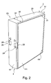
- FIG. 1 there is a simplified perspective view of a package 2 for tobacco related articles, according to a first embodiment of the invention.
- the package 2 comprises a frame 4, a first compartment 6 and a second compartment 8.
- the compartments 6, 8 are for accommodating tobacco related articles, in particular for accommodating cigarettes 10.
- the first compartment 6 is hinged to the frame 4 by a first hinge H1.
- the second compartment 8 is hinged to the frame 4 via a second hinge H2.
- the package 2 may be opened and closed by swiveling the first compartment 6 around the first hinge H1 and / or by swiveling the second compartment 8 around the second hinge H2.
- the two compartments 6 and 8 may be opened and closed separately to provide access to either one of the first compartment 6 and the second compartment 8.
- the first compartment 6 and the second compartment 8 each comprise a front wall F1, F2, a rear wall R1, R2, a first side wall S1, S2, a second side wall S3, S4 and a bottom wall B1, B2.
- the front walls F1, F2 and the rear walls R1, R2 are opposite to each other with respect to an interior of either one of the compartments 6 and 8 which accommodate the tobacco related articles. Similar, the side walls S1..S4 are arranged opposite to each other with respect to the compartments 6, 8.
- the front walls F1, F2, the rear walls R1, R2, the first side walls S1, S2 and the second side walls S3, S4 project substantially perpendicular to the bottom walls B1, B2.
- each compartment 6, 8 comprises an access opening 12 for providing access to the interior of the first compartment 6 and the second compartment 8, respectively.
- first hinge H1 and the second hinge H2 are substantially parallel to each other and there is a clearance 14 between the hinges H1 and H2.
- the frame 4 comprises four substantially flat bars: a front bar 16, a rear bar 18, a top bar 20 and a bottom bar 22.
- the front bar 16 covers the first side walls S1, S2, the rear bar 18 covers the second side walls S3, S4, the top bar 20 covers the access openings 12 and the bottom bar 22 covers the bottom walls B1, B2.
- the clearance 14 has a width that (substantially) corresponds to the combined widths of the second side walls S3 and S4.
- the clearance 14 may be greater than the combined widths of the second side walls S3 and S4 so as to provide a package 2 having a desired thickness.
- the clearance 14 may also be larger than the combined width of the first and the second compartment in order to provide an additional space between the two compartments. This additional space may then be used for accommodating advertisement or other information, for example in form of a folded sheet of paper. Even a small additional compartment or box may be provided between the two compartments. This compartment may contain promotional or other information material.
- FIG. 2 which is another simplified perspective view, the package 2 is closed.
- the front wall F1 of the first compartment 6 is a front side wall of the package 2.
- a front wall F2 of the second compartment 8 is a rear side wall of the package 2.
- the recesses 24, 26 are arranged opposite to each other.
- the first recess 24 is for accommodating a first protrusion 28 of the front wall F1 of the first compartment 6.
- This first protrusion 28 serves as a handle to facilitate opening of the first compartment 6 by swiveling the compartment 6 around the first hinge H1.
- the front wall F2 of the second compartment 8 comprises a similar protrusion 29, which is accommodated in the second recess 26, when the second compartment 8 is in a closed state.
- the second protrusion 29 is to facilitate swiveling the second compartment 8 around the second hinge H2.
- the first hinge H1 is arranged along an edge of the first compartment 6 which is between the front side F1 of the first compartment 6, which is the front side wall of the package 2, and the second side wall S3 of the first compartment 6.
- the second hinge H2 is arranged along the front wall F2 of the second compartment 8 (which is the backside wall of the package 2) and the second side wall S4 of the second compartment 8.
- a front side rim 31 and a backside rim of the frame 4 may be provided with a bevel 30.
- the front side rim 31, which is adjacent to the front side wall of the package 2, may be flush with the front side of the package 2.
- the backside rim may be flush with the backside wall of the package 2.
- a width 32 of the top bar 20 may be chosen in that the access openings 12 of the first compartment 6 and the second compartment 8 are covered and / or sealed by the top bar 20, when the package 2 is in its closed state. Furthermore, the width 32 of the top bar 20 defines the clearance 14 between the first hinge H1 and the second hinge H2. In particular, the four bars16..22 of the frame 4 may have an equal width, which may be for example the width 32 of the top side bar 20.
- FIG. 3 is a simplified front side view of the package 2 according to the embodiment of FIGs. 1 and 2 .
- the package 2 may have a length L which is between 50 mm and 150 mm.
- the length L may be between 80 mm and 110 mm, in particular, the length L may be approx. 90 mm.
- a height H of the package 2 may be of a similar dimension, which means, the value of the height H is between 50 mm and 150 mm, in particular between 80 mm and 110 mm and may be approx. 90 mm.
- a width W of the package 2 (see FIG. 4 ) may be between 10 mm and 20 mm. The width W may correspond to the width of the clearance 14 between the first hinge H1 and second hinge H2.
- width W corresponds to the combined widths of the second side walls S3 and S4 of the first and the second compartment 6, 8.
- a width WB of the bevel 30 may be about 1 mm to 5 mm.
- the frame 4 may be manufactured from a synthetic material, for example from PP or ABS.
- the first compartment 6 and the second compartment 8, to be more precise, the walls F1, F2, R1, R2, S1..S4 and the bottom B1, B2 of the compartments 6, 8, may be manufactured from card-board or paperboard material. The dimensions and materials are advantageously applicable to all embodiments of the invention.
- FIG. 4 there is a simplified front side view of the package 2 according to the embodiment and in FIG. 5 there is a simplified top side view of this package 2.
- the package 2 is in a closed state.
- FIG. 6 is a simplified view showing a package 2, according to an embodiment of the invention.
- the package 2 comprises two compartments 6, 8, wherein the second compartment 8 is opened. For opening the second compartment 8, it has been swiveled around the second hinge H2.
- the rear wall R2 of the second compartment 8 faces the rear wall R1 of the first compartment 6.
- the rear walls R1, R2 abut a stop 34, when the compartments 6, 8 are in their closed position.
- the stop 34 projects into an interior of the frame 4 by a width WS, which may be between 3 mm an 10 mm.
- the stop 34 may be a rim which is injection molded together with the frame 4 and which substantially projects perpendicular from the front bar 16.
- the stop 34 defines the closed position of the first compartment 6 and the closed position of the second compartment 8.
- a sum of the width of the first compartment 6 and the width of the second compartment 8 (which is determined in the direction of the width W of the package 2; see FIG. 4 ) and a material strength of the rim (which is considered in the direction), may be configured in that the front wall F1 of the first compartment 6 and the front wall F2 of the second compartment 8 are flush with the rims of the frame 4.
- the four bars of the frame 4, namely the front bar 16, the rear bar 18, the top bar 20 and the bottom bar 22 may comprise bevels 30 adjacent to the outer rim of the frame 4. Further, the frame 4 may be reinforced in that, the four bars 16, 18, 20, 22 are connected by reinforcement members 36. These members 36 project into the interior of the frame 4 and connect adjacent bars 16..22. The reinforcement members 36 are particularly useful for taking up sheer forces which are applied to the frame 4.
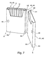
- FIG. 7 there is another simplified perspective view showing a prefabricated part of the package 2, according to an embodiment of the invention.
- the interconnecting panel 40 further comprises an intermediate wall 42 which connects the front wall F1 of the first compartment 6 and the front wall F2 of the second compartment 8.
- the interconnecting panel 40 is an integral part comprising the front walls F1, F2 and the intermediate wall 42.
- the first compartment 6 and the second compartment 8 may be prefabricated members which are subsequently attached to the interconnecting panel 40. This may be advantageous with respect to manufacture of the package 2.
- the interconnecting panel 40 may be manufactured from a first part comprising the first compartment 6 and a second part comprising the second compartment 8.
- a front side wall F1 of this first compartment 6 may extend over the compartment 6 so as to provide at least a part of the intermediate wall 42.
- the front side wall F2 of this second compartment 8 may extend over the compartment 8 so as to provide at least a part of the intermediate wall 42. If both, the first part and the second part each provide an intermediate wall 42, these two intermediate walls 42 may be arranged so as to overlap. This will result in the member which is depicted in FIG. 7 .
- the intermediate wall 42 is a double wall, according to this embodiment of the invention.
- the first part and the second part may be manufactured separately.
- the first and second hinge H1, H2 are provided by folding lines in the interconnecting panel 40.
- the interconnecting panel 40 may be manufactured from card-board or paperboard material.
- a backside surface 44 of the intermediate wall 42 may be fixed to an inner surface of the rear bar 18 of the frame 4.
- An inner surface of the rear bar 18 is a surface facing the interior of the frame 4.
- the intermediate wall 42 may be fixed to the rear bar 18 using a suitable adhesive.
- the rear wall R1 of the first compartment 6 and the rear wall R2 of the second compartment 8 may be provided with fixing members 46 for fixing the first compartment 6 and the second compartment 8 in their closed position.
- the fixing members 46 may be antagonistic magnets which apply an attractive force on each other if the package 2 is closed.
- the fixing members 46 may be opposite parts of a hook-and-loop fastener (velcro strap) or dots of a releasable adhesive.
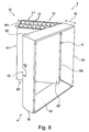
- FIG. 8 is a simplified perspective view showing a package 2 having a single compartment (construction not covered by the present invention).
- the package 2 may be configured similar to the package 2 according to the embodiments in FIGs. 1 to 7 , however, the package 2 comprises a single compartment 70 which is hinged to the frame 4 via a hinge H.
- the compartment 70 is swiveled around the hinge H.
- the compartment 70 comprises a front wall F7 and a rear wall R7 which are substantially parallel to each other and which project substantially perpendicular from a bottom wall B7.
- the front wall F7 and a rear wall R7 are opposite to each other with respect to an interior of the compartment 70.
- a first side wall S7 and a second side wall S8 are substantially parallel to each other and project substantially perpendicular from the bottom wall B7.
- the side walls S7, S8 are opposite to each other with respect to the interior space of the compartment 70.
- the frame 4 comprises four substantially flat bars: a front bar 16, a rear bar 18, a top bar 20 and a bottom bar 22.
- the front bar 16 covers the first side wall S7
- the rear bar 18 covers the second side wall S8,
- the top bar 20 covers an access opening 12
- the bottom bar 22 covers the bottom wall B7.
- the access opening is for accessing the tobacco related articles, for example cigarettes 10, which are arranged in the compartment 70.
- a width W of the frame 4 may be similar or equal to a width W7 of the compartment 70.
- a width of the side walls S7, S8 of the compartment 70 which is equal to the width W7 of the compartment 70, is similar or equal to a width of the bars 16..22 of the frame 4.
- the top bar 20 may be arranged to seal or close the access opening 12 of the compartment 70, when the package 2 is in the closed state.
- the rear wall R7 of the compartment 70 is a front wall of the package 2
- the front wall F7 of the compartment 70 is a rear wall of the package 2.
- the frame 4 of the package in FIG. 8 may have a recess 72.
- the frame 4 comprises a single recess 72.
- the front wall F7 of the compartment 70 may have a protrusion (not shown) which is accommodated in the recess 72, when the package 2 is in a closed state, and which facilitates opening of the compartment 70.
- the frame 4 may be configured to have a separate front wall (not shown) for closing a side or aperture of the frame 4. Through this aperture, the rear wall R7 of the compartment 70 is visible in the embodiment of FIG. 8 . This will be not the case, when the frame is provided with the separate front wall.
- the set 50 comprises a front panel 52 which is for covering the front side F1 of the first compartment 6, a backside panel 54 which is for covering a front side F2 of the second compartment 8 (which is the backside wall of the package 2) and for side panels 56, 58, 60, 62.
- the side panels 56..62 comprise a backside panel 56 which is for covering an outer surface of the rear bar 18.
- a front side panel 58 is for covering an outer surface of the front bar 16 of the frame 4.
- the top panel 60 is for covering an outer surface of the top bar 20 and the bottom panel 62 for covering an outer surface of the bottom bar 22 of the frame 4.
- the set 50 of panels may be applied to a package 2 according to the embodiment in FIG. 8 .
- the front panel 52 covers the rear side R7 of the compartment 6 and the backside panel 54 covers the front side F7.
- the side panels 56, 58, 60, 62 are for covering the frame 4 as mentioned before.
- the panels 54..60 may be provided with riffles or an embossing so as to provide the package 2 with an appealing design.
- the panels 54..60 are fixed to the respective outer surfaces of the package 2 using a suitable adhesive.
Description
- The invention relates to a package for tobacco related articles having at least one compartment for accommodating the tobacco related articles. The invention also relates to a method of manufacturing a package for tobacco related articles.
- Tobacco related articles, preferably smoking articles like cigarettes or cigarillos, are often contained in disposable packages having a substantially cuboid or parallelepiped shape. A widespread type of a cigarette package is the hinged lid package. This type of package comprises a front wall and a rear wall and a pair of smaller longitudinal side walls. The walls of the package project substantially perpendicular from a bottom wall and surround a compartment for accommodating the smoking articles. Opposite to the bottom wall, there is an access opening at the top side of the package through which the smoking articles are accessible. The access opening is covered by a lid which is hinged to the rear wall.
- A variety of different packages is known, ranging from soft packs to classical cigarette or cigar boxes. Packages for tobacco related articles which depart from the classical hinged lid design as described above are becoming more and more popular, for example, packages having a plurality of containers or boxes for accommodation of the smoking articles.
- In document
WO2010/060829 , there is a package having three separate compartments. A common panel holds up the three containers side-by-side. When the package is opened, the panel is arranged at the backside of the containers. The package is foldable along several hinge lines in the backside panel and when the package is fold-up, the panel forms an exterior surface of the package. - Another multi-compartment package is disclosed in
US 5,344,008 . This cigarette package comprises a plurality of boxes which are bonded together using a binding member. The binding member fixes the individual boxes like a book jacket or book binder fixes the individual pages of a book. - Still other packages having swing-open mechanisms are known from
EP 2 017 198 A1WO 88/08602 DE 20 2007 012 493 U1DE 1 947 795 andEP 2 277 804 A1 . However, none of the known packages provides sufficient accessibility of the content in combination with sufficient stability of the entire package. - It is an object of the invention to provide an improved package for tobacco related articles and an improved method of manufacturing a package for tobacco related articles.
- The object is solved by the subject matter of
claims 1 and 8. - According to the invention, the package comprises a first compartment and a second compartment. The first compartment and the second compartment may each comprise a bottom wall, a front wall, a rear wall, a first side wall and a second side wall. The walls of the compartment may project substantially perpendicular from the bottom wall. The front wall and the rear wall are opposite to each other with respect to an interior of the compartment. Similar, the first side wall and the second side wall are opposite to each other with respect to the interior of the compartment. The front wall and the rear wall are substantially parallel to each other. The first side wall and the second side wall are likewise substantially parallel to each other. The first compartment and the second compartment may have a substantially parallelepiped or cuboid shape. The front wall and the rear wall may be the broad surfaces and the side walls may be the small surfaces of this cuboid. In particular, the side walls are smaller when compared to the front wall and the rear wall and if considered in a plane which is substantially parallel to the bottom wall. Opposite to the bottom wall, the first compartment and the second compartment each comprise an access opening for providing access to the compartment.
- According to the invention, there is a clearance between the first hinge and the second hinge. The clearance may have a width that corresponds to two times the width of the first or second side wall. The clearance may also have a width that corresponds to the sum of the widths of the first and the second compartment.
- The clearance may also be larger than the combined width of the first and the second compartment in order to provide an additional space between the two compartments. This additional space may then be used for accommodating advertisement or other information, for example in form of a folded sheet of paper. Even a small additional compartment or box may be provided between the two compartments. This compartment may contain promotional or other information material.
- The frame may then at least partially (or completely) cover the bottom wall, the first side wall, the second side wall and the access openings of the first compartment and the second compartment, when the package is in a closed state.
- The bottom wall, the front wall, the rear wall, the first side wall and / or the second side wall of the first compartment and / or the second compartment may be manufactured from rigid or half-rigid material, for example from card-board or paperboard material.
- Multi-compartment packages according to the prior art often lack durability due to their individual compartments becoming detached from the rest of the package. Furthermore, a provision of several compartments has often resulted in packages being relatively fragile which means that the package quickly becomes worn when it is used.
- The package according to aspects of the invention overcomes these drawbacks. An easy to handle, hard-wearing package is provided. The frame surrounding the first and second compartment serves as a protective member for the package and for the smoking articles. The smoking articles inside the package will not be damaged and the durable package will keep its attractive visual appearance after frequent use for a long period of time.
- Preferably, the frame is manufactured using four substantially flat bars, namely a front bar, a rear bar, a top bar and a bottom bar. The four bars of the frame cover at least partially the side walls, the bottom wall and the access opening of the at least one package. If the package comprises a first compartment and a second compartment, the four bars of the frame will cover at least partially the side walls, the bottom walls and the access openings of the first compartment and the second compartment. The front bar may be configured to cover the first side wall(s) when the package (of both compartments) is in the closed state. The rear bar is configured to cover the second side wall(s) when the package is in the closed state. The top bar is configured to cover the access opening(s) or top side(s) of the at least one compartment (of both compartments) when the package is in the closed state. The bottom bar of the frame is configured to cover the bottom wall(s) of the at least one compartment when the package (when the two compartments) is (are) in the closed state. The coverage of the respective bars of the frame is considered when the package is closed. The coverage applies to a package having a single compartment and to a package having a plurality of compartment. For a package having for example two compartments, the first compartment and the second compartment may be hinged to the rear bar of the frame.
- A width of the top bar may be chosen in that the access opening of the first compartment and the access opening of the second compartment is covered by the top bar, when the package is in the closed state. If the top bar covers the access openings, the compartments may be designed without a lid. The bars of the frame may be configured to have substantially the same width. The frame offers a smooth front side rim and backside rim which may be flush with the front wall of the first compartment and with the front wall of the second compartment. The front wall of the first compartment may be a front side wall of the package and the front wall of the second compartment may be a backside wall of the package, if the package is closed.
- Advantageously, the front bar of the frame comprises at least one recess. In particular, the front bar may comprise a first recess and a second recess, which may be further arranged to be opposite to each other. The front wall of the at least one compartment may comprise a protrusion which preferably serves as a handle for opening the compartment and which projects into the recess. If the package comprises a first compartment and a second compartment, the front wall of the first compartment and / or the front wall of the second compartment may comprise a protrusion which preferably serves as a handle for opening a respective one of the compartments.
- According to another advantageous embodiment of the invention, the frame comprises a stop which projects into an interior of the frame and which is arranged in that at least a part of the rear wall of the first compartment and / or at least a part of the rear wall of the second compartment abuts the stop, if the package is closed. Preferably, the stop is a rim with projects into the interior of the frame and which is attached to an inner surface of the front bar of the frame. The stop defines a closed position of the first compartment and a closed position of the second compartment.
- Preferably, the front wall of the first compartment and the front wall of the second compartment form part of an interconnecting panel which further comprises an intermediate wall. The intermediate part is connected to the front wall of the first compartment and to the front wall of the second compartment. The hinges may be formed by folding lines in the interconnecting panel. In particular, there may be a first folding line providing the first hinge between the front wall of the first compartment and the intermediate wall. A second folding line for providing the second hinge may be arranged between the front wall of the second compartment and the intermediate wall. The interconnecting panel may be manufactured from a rigid or half rigid material, for example from card-board or paperboard material.
- According to an advantageous aspect of the invention, the intermediate wall of the interconnecting panel is fixed to the frame. In particular, the intermediate wall may be fixed to an inner surface of the rear bar of the frame.
- According to another advantageous embodiment of the invention, the first hinge is arranged along an edge which is between the front wall and the first or second side wall of the first compartment. The second hinge is preferably arranged along an edge which is between the front wall and the first or a second side wall of the second compartment. The hinges are arranged at / or in close proximity to the edges of the package.
- According to another embodiment of the invention, the rear wall of the first compartment and the rear wall of the second compartment face each other, if the package is closed. Accordingly, the front wall of the first compartment is a front side wall of the package and the front wall of the second compartment is a backside wall of the package.
- According to another aspect of the invention, a method of manufacturing a package for tobacco related articles is provided. A package is manufactured comprising a first compartment and a second compartment for accommodating the tobacco related articles. A front wall of the first compartment and a front wall of the second compartment form part of an interconnecting panel. This panel further comprises an intermediate wall which interconnects the front wall of the first compartment and the front wall of the second compartment. The intermediate wall is fixed to a frame. In particular, the frame comprises four bars and the intermediate wall is connected to in inner side of one of the four bars. An inner side is a side which faces an interior of the frame. By connecting the intermediate wall to the frame, a hinged connection between the first compartment and the frame and the second compartment and the frame may be provided. The package may be opened and closed by swiveling the first compartment around the first hinge and by swiveling the second compartment around the second hinge.
- Advantageously, the frame, on the one hand, and the first and the second compartment together with the interconnecting wall, on the other hand, may be manufactured separately. This is advantageous because the two parts may be manufactured using different materials. The frame may be manufactured from a synthetic material. The first and the second compartment may be manufactured using a card-board or paperboard material. The two pre-fabricated parts are joined in a subsequent production step. For instance, the frame and the intermediate wall are fixed using a suitable adhesive.
- Further aspects and characteristics of the invention ensue from the following description of preferred embodiments of the invention with reference to the accompanying drawings, wherein
-
FIG. 1 is a simplified perspective view of a package having two compartments, according to an embodiment of the invention, wherein the package is in an opened state, -
FIG. 2 is a simplified perspective view of the package ofFIG. 1 showing the package in a closed state, -
FIG. 3 is a simplified front side view of this package, -
FIG. 4 is a simplified side view of this package, -
FIG. 5 is a simplified top side view of this package, -
FIG. 6 is a simplified view showing the package ofFIG. 1 from its back side, wherein one of the compartments is opened, -
FIG. 7 is a simplified perspective view of a first and a second compartment which are connected by an intermediate wall for manufacturing a package according to another embodiment of the invention, -
FIG.8 is a simplified perspective view of a package having a single compartment, wherein the package is in an opened state, (construction not covered by the present invention), -
FIG. 9 is a set of panels for covering a package according to embodiments of the invention. - In
FIG. 1 , there is a simplified perspective view of apackage 2 for tobacco related articles, according to a first embodiment of the invention. Thepackage 2 comprises aframe 4, afirst compartment 6 and asecond compartment 8. Thecompartments cigarettes 10. - The
first compartment 6 is hinged to theframe 4 by a first hinge H1. Thesecond compartment 8 is hinged to theframe 4 via a second hinge H2. Thepackage 2 may be opened and closed by swiveling thefirst compartment 6 around the first hinge H1 and / or by swiveling thesecond compartment 8 around the second hinge H2. The twocompartments first compartment 6 and thesecond compartment 8. - The
first compartment 6 and thesecond compartment 8 each comprise a front wall F1, F2, a rear wall R1, R2, a first side wall S1, S2, a second side wall S3, S4 and a bottom wall B1, B2. The front walls F1, F2 and the rear walls R1, R2 are opposite to each other with respect to an interior of either one of thecompartments compartments compartment first compartment 6 and thesecond compartment 8, respectively. - According to the embodiment, the first hinge H1 and the second hinge H2 are substantially parallel to each other and there is a
clearance 14 between the hinges H1 and H2. - The
frame 4 comprises four substantially flat bars: afront bar 16, arear bar 18, atop bar 20 and abottom bar 22. Thefront bar 16 covers the first side walls S1, S2, therear bar 18 covers the second side walls S3, S4, thetop bar 20 covers theaccess openings 12 and thebottom bar 22 covers the bottom walls B1, B2. - According to the embodiment, the
clearance 14 has a width that (substantially) corresponds to the combined widths of the second side walls S3 and S4. However, theclearance 14 may be greater than the combined widths of the second side walls S3 and S4 so as to provide apackage 2 having a desired thickness. - The
clearance 14 may also be larger than the combined width of the first and the second compartment in order to provide an additional space between the two compartments. This additional space may then be used for accommodating advertisement or other information, for example in form of a folded sheet of paper. Even a small additional compartment or box may be provided between the two compartments. This compartment may contain promotional or other information material. - In
FIG. 2 , which is another simplified perspective view, thepackage 2 is closed. The front wall F1 of thefirst compartment 6 is a front side wall of thepackage 2. Similar, a front wall F2 of thesecond compartment 8 is a rear side wall of thepackage 2. - There is a
first recess 24 and asecond recess 26 in thefront bar 16. Therecesses first recess 24 is for accommodating afirst protrusion 28 of the front wall F1 of thefirst compartment 6. Thisfirst protrusion 28 serves as a handle to facilitate opening of thefirst compartment 6 by swiveling thecompartment 6 around the first hinge H1. The front wall F2 of thesecond compartment 8 comprises asimilar protrusion 29, which is accommodated in thesecond recess 26, when thesecond compartment 8 is in a closed state. Thesecond protrusion 29 is to facilitate swiveling thesecond compartment 8 around the second hinge H2. - The first hinge H1 is arranged along an edge of the
first compartment 6 which is between the front side F1 of thefirst compartment 6, which is the front side wall of thepackage 2, and the second side wall S3 of thefirst compartment 6. The second hinge H2 is arranged along the front wall F2 of the second compartment 8 (which is the backside wall of the package 2) and the second side wall S4 of thesecond compartment 8. - A front side rim 31 and a backside rim of the
frame 4 may be provided with abevel 30. Thefront side rim 31, which is adjacent to the front side wall of thepackage 2, may be flush with the front side of thepackage 2. Similar, the backside rim may be flush with the backside wall of thepackage 2. - A
width 32 of thetop bar 20 may be chosen in that theaccess openings 12 of thefirst compartment 6 and thesecond compartment 8 are covered and / or sealed by thetop bar 20, when thepackage 2 is in its closed state. Furthermore, thewidth 32 of thetop bar 20 defines theclearance 14 between the first hinge H1 and the second hinge H2. In particular, the four bars16..22 of theframe 4 may have an equal width, which may be for example thewidth 32 of thetop side bar 20. -
FIG. 3 is a simplified front side view of thepackage 2 according to the embodiment ofFIGs. 1 and2 . In particular, thepackage 2 may have a length L which is between 50 mm and 150 mm. Furthermore, the length L may be between 80 mm and 110 mm, in particular, the length L may be approx. 90 mm. A height H of thepackage 2 may be of a similar dimension, which means, the value of the height H is between 50 mm and 150 mm, in particular between 80 mm and 110 mm and may be approx. 90 mm. A width W of the package 2 (seeFIG. 4 ) may be between 10 mm and 20 mm. The width W may correspond to the width of theclearance 14 between the first hinge H1 and second hinge H2. This means that the width W corresponds to the combined widths of the second side walls S3 and S4 of the first and thesecond compartment bevel 30 may be about 1 mm to 5 mm. Theframe 4 may be manufactured from a synthetic material, for example from PP or ABS. Thefirst compartment 6 and thesecond compartment 8, to be more precise, the walls F1, F2, R1, R2, S1..S4 and the bottom B1, B2 of thecompartments - In
FIG. 4 there is a simplified front side view of thepackage 2 according to the embodiment and inFIG. 5 there is a simplified top side view of thispackage 2. In bother figures, thepackage 2 is in a closed state. -
FIG. 6 is a simplified view showing apackage 2, according to an embodiment of the invention. Thepackage 2 comprises twocompartments second compartment 8 is opened. For opening thesecond compartment 8, it has been swiveled around the second hinge H2. When thepackage 2 is closed, the rear wall R2 of thesecond compartment 8 faces the rear wall R1 of thefirst compartment 6. Furthermore, the rear walls R1, R2 abut astop 34, when thecompartments stop 34 projects into an interior of theframe 4 by a width WS, which may be between 3 mm an 10 mm. Thestop 34 may be a rim which is injection molded together with theframe 4 and which substantially projects perpendicular from thefront bar 16. - The
stop 34 defines the closed position of thefirst compartment 6 and the closed position of thesecond compartment 8. A sum of the width of thefirst compartment 6 and the width of the second compartment 8 (which is determined in the direction of the width W of thepackage 2; seeFIG. 4 ) and a material strength of the rim (which is considered in the direction), may be configured in that the front wall F1 of thefirst compartment 6 and the front wall F2 of thesecond compartment 8 are flush with the rims of theframe 4. - The four bars of the
frame 4, namely thefront bar 16, therear bar 18, thetop bar 20 and thebottom bar 22 may comprisebevels 30 adjacent to the outer rim of theframe 4. Further, theframe 4 may be reinforced in that, the fourbars reinforcement members 36. Thesemembers 36 project into the interior of theframe 4 and connectadjacent bars 16..22. Thereinforcement members 36 are particularly useful for taking up sheer forces which are applied to theframe 4. - In
FIG. 7 , there is another simplified perspective view showing a prefabricated part of thepackage 2, according to an embodiment of the invention. There is thefirst compartment 6 and thesecond compartment 8, wherein the front wall F1 of thefirst compartment 6 and the front wall F2 of thesecond compartment 8 form part of an interconnecting panel 40. The interconnecting panel 40 further comprises an intermediate wall 42 which connects the front wall F1 of thefirst compartment 6 and the front wall F2 of thesecond compartment 8. The interconnecting panel 40 is an integral part comprising the front walls F1, F2 and the intermediate wall 42. Thefirst compartment 6 and thesecond compartment 8 may be prefabricated members which are subsequently attached to the interconnecting panel 40. This may be advantageous with respect to manufacture of thepackage 2. - Furthermore, the interconnecting panel 40 may be manufactured from a first part comprising the
first compartment 6 and a second part comprising thesecond compartment 8. A front side wall F1 of thisfirst compartment 6 may extend over thecompartment 6 so as to provide at least a part of the intermediate wall 42. Similar, the front side wall F2 of thissecond compartment 8 may extend over thecompartment 8 so as to provide at least a part of the intermediate wall 42. If both, the first part and the second part each provide an intermediate wall 42, these two intermediate walls 42 may be arranged so as to overlap. This will result in the member which is depicted inFIG. 7 . However, the intermediate wall 42 is a double wall, according to this embodiment of the invention. Advantageously, the first part and the second part may be manufactured separately. - The first and second hinge H1, H2 are provided by folding lines in the interconnecting panel 40. For example, the interconnecting panel 40 may be manufactured from card-board or paperboard material.
- For manufacture of the
package 2 according to embodiments of the invention, abackside surface 44 of the intermediate wall 42 may be fixed to an inner surface of therear bar 18 of theframe 4. An inner surface of therear bar 18 is a surface facing the interior of theframe 4. The intermediate wall 42 may be fixed to therear bar 18 using a suitable adhesive. - Furthermore, the rear wall R1 of the
first compartment 6 and the rear wall R2 of thesecond compartment 8 may be provided with fixingmembers 46 for fixing thefirst compartment 6 and thesecond compartment 8 in their closed position. For example, the fixingmembers 46 may be antagonistic magnets which apply an attractive force on each other if thepackage 2 is closed. The fixingmembers 46 may be opposite parts of a hook-and-loop fastener (velcro strap) or dots of a releasable adhesive. -
FIG. 8 is a simplified perspective view showing apackage 2 having a single compartment (construction not covered by the present invention). Thepackage 2 may be configured similar to thepackage 2 according to the embodiments inFIGs. 1 to 7 , however, thepackage 2 comprises asingle compartment 70 which is hinged to theframe 4 via a hinge H. For opening and closing thepackage 2, thecompartment 70 is swiveled around the hinge H. Thecompartment 70 comprises a front wall F7 and a rear wall R7 which are substantially parallel to each other and which project substantially perpendicular from a bottom wall B7. The front wall F7 and a rear wall R7 are opposite to each other with respect to an interior of thecompartment 70. Similar, a first side wall S7 and a second side wall S8 are substantially parallel to each other and project substantially perpendicular from the bottom wall B7. The side walls S7, S8 are opposite to each other with respect to the interior space of thecompartment 70. - The
frame 4 comprises four substantially flat bars: afront bar 16, arear bar 18, atop bar 20 and abottom bar 22. Thefront bar 16 covers the first side wall S7, therear bar 18 covers the second side wall S8, thetop bar 20 covers anaccess opening 12 and thebottom bar 22 covers the bottom wall B7. The access opening is for accessing the tobacco related articles, forexample cigarettes 10, which are arranged in thecompartment 70. A width W of theframe 4 may be similar or equal to a width W7 of thecompartment 70. In other words, a width of the side walls S7, S8 of thecompartment 70, which is equal to the width W7 of thecompartment 70, is similar or equal to a width of thebars 16..22 of theframe 4. Thetop bar 20 may be arranged to seal or close the access opening 12 of thecompartment 70, when thepackage 2 is in the closed state. In this closed state, the rear wall R7 of thecompartment 70 is a front wall of thepackage 2, the front wall F7 of thecompartment 70 is a rear wall of thepackage 2. Similar to thepackage 2 inFIGs. 1 to 7 , theframe 4 of the package inFIG. 8 may have arecess 72. There is asingle compartment 70, accordingly, theframe 4 comprises asingle recess 72. The front wall F7 of thecompartment 70 may have a protrusion (not shown) which is accommodated in therecess 72, when thepackage 2 is in a closed state, and which facilitates opening of thecompartment 70. - However, the
frame 4 may be configured to have a separate front wall (not shown) for closing a side or aperture of theframe 4. Through this aperture, the rear wall R7 of thecompartment 70 is visible in the embodiment ofFIG. 8 . This will be not the case, when the frame is provided with the separate front wall. - In
FIG. 9 , there is aset 50 of panels which may be applied to the outer surface of thepackage 2 inFIGs. 1 to 7 . Theset 50 comprises afront panel 52 which is for covering the front side F1 of thefirst compartment 6, abackside panel 54 which is for covering a front side F2 of the second compartment 8 (which is the backside wall of the package 2) and forside panels side panels 56..62 comprise abackside panel 56 which is for covering an outer surface of therear bar 18. Afront side panel 58 is for covering an outer surface of thefront bar 16 of theframe 4. Thetop panel 60 is for covering an outer surface of thetop bar 20 and thebottom panel 62 for covering an outer surface of thebottom bar 22 of theframe 4. Furthermore, theset 50 of panels may be applied to apackage 2 according to the embodiment inFIG. 8 . For thepackage 2, thefront panel 52 covers the rear side R7 of thecompartment 6 and thebackside panel 54 covers the front side F7. Theside panels frame 4 as mentioned before. - The
panels 54..60 may be provided with riffles or an embossing so as to provide thepackage 2 with an appealing design. Thepanels 54..60 are fixed to the respective outer surfaces of thepackage 2 using a suitable adhesive.
Claims (8)
- A package (2) for tobacco related articles (10) comprising a first compartment (6) and a second compartment (8) for accommodating the tobacco related articles (10) and the first compartment (6) is hinged to the frame (4) by a first hinge (H1) and the second compartment (8) is hinged to the frame (4) by a second hinge (H1), wherein the package (2) may be opened and closed by swiveling the first compartment (6) around the first hinge (H1) and by swiveling the second compartment (8) around the second hinge (H2), wherein the first hinge (H1) and the second hinge (H2) are separate and substantially parallel to each other and there is a clearance (14) between the first hinge (H1) and the second hinge (H2), wherein the first compartment (6) and the second compartment (6) are at least partially surrounded by the frame (4), when the package (2) is in a closed state characterized in that a front wall (F1) of the first compartment (6) and a front wall (F2) of the second compartment (8) form part of an interconnecting panel (40) which further comprises an intermediate wall (42), wherein the intermediate wall (42) is fixed to the frame (4) for connecting the front wall (F1) of the first compartment (6) and the front wall (F2) of the second compartment (8) to the frame (4) and wherein the frame (4) at least partially covers an access opening (12) of the first compartment (6) and an access opening (12) of the second compartment (8), when the package (2) is in a closed state.
- The package (2) according to claim 1, wherein the first and second compartment comprises a bottom wall (B1, B2), a front wall (F1, F2), a rear wall (R1, R2), a first side wall (S1, S2) and a second side wall (S3, S4), wherein the front wall (F1, F2) and the rear wall (R1, R2) are opposite to each other with respect to an interior of the compartment (6, 8) and the first side wall (S1, S2) and the second side wall (S3, S4) are opposite to each other with respect to the interior of the compartment (6, 8), and wherein the access opening (12) for providing access to the compartment (6, 8) is arranged opposite to the bottom wall (B1, B2), and wherein the frame (4) at least partially covers the bottom wall (B1, B2), the first side wall (S1, S2), the second side wall (S3, S4) and the access opening (12) of the first and second compartment (6, 8) respectively, when the package is in a closed state.
- The package (2) according to claim 1 or 2, wherein the first hinge (H1) is arranged along an edge which is arranged between the front wall (F1) and the first side wall (S1) or the second side wall (S3) of the first compartment and the second hinge (H2) is arranged along an edge which is arranged between the front wall (F2) and the first side wall (S2) or the second side wall (S4) of the second compartment.
- The package (2) according to one of the preceding claims, wherein the frame (4) is manufactured using four substantially flat bars, namely a front bar (16), a rear bar (18), a top bar (20) and a bottom bar (22), and wherein the front bar (16) at least partially covers the first side walls (S1, S3), the rear bar (18) at least partially covers the second side walls (S2, S4), the top bar (20) at least partially covers the access openings (12) and the bottom bar (22) at least partially covers the bottom walls (B1, B2) of the first and second compartment (6, 8) respectively, when the package (2) is in a closed state.
- The package (2) according to claim 4, wherein the front bar (16) of the frame (4) comprises at least one recess (24, 26) and the front wall (F1, F2) of the first and/or second compartment (6, 8) comprises a protrusion (28, 29) which projects into the recess (24, 26).
- The package (2) according to anyone of the preceding claims, wherein the frame (4) comprises a stop (34) which projects into an interior of the frame (4), wherein at least a part of the rear wall (R1, R2) of the first and/or second compartment (6, 8) abuts the stop (34), when the package (2) is in a closed state.
- The package (2) according to anyone of claims 2 to 6, wherein the rear wall (R1) of the first compartment (6) and the rear wall (R2) of the second compartment (8) face each other if the package (2) is closed and the front wall (F1) of the first compartment (6) forms a front-side wall of the package (2) and the front wall (F2) of the second compartment (8) forms a back-side wall of the package (2).
- A method of manufacturing a package (2) for tobacco related articles (10), the package comprising a first compartment (6) and a second compartment (6) for accommodating the tobacco related articles (10), wherein a front wall (F1) of the first compartment (6) and a front wall (F2) of the second compartment (8) form part of an interconnecting panel (40) which further comprises an intermediate wall (42), the method comprising the step of fixing the intermediate wall (42) to a frame (4) so as to provide a hinged connection between the first compartment (6) and the frame (4) and the second compartment (8) and the frame (4), wherein the package (2) is configured to be opened and closed by swiveling the first compartment (6) around the first hinge (H1) and by swiveling the second compartment (8) around the second hinge (H2) such that the frame (4) at least partially covers an access opening (12) of the first compartment (6) and an access opening (12) of the second compartment (8), when the package (2) is in a closed state.
Priority Applications (7)
| Application Number | Priority Date | Filing Date | Title |
|---|---|---|---|
| EP12186947.3A EP2716574B1 (en) | 2012-10-02 | 2012-10-02 | Package for tobacco related articles and method of manufacturing the package |
| ES12186947.3T ES2562162T3 (en) | 2012-10-02 | 2012-10-02 | Package for tobacco related items and package manufacturing method |
| EP13770940.8A EP2903913A1 (en) | 2012-10-02 | 2013-10-02 | Package for tobacco related articles and method of manufacturing the package |
| RU2015115722A RU2607763C2 (en) | 2012-10-02 | 2013-10-02 | Package for tobacco products and method of producing package |
| UAA201504131A UA114932C2 (en) | 2012-10-02 | 2013-10-02 | TOBACCO PACKAGING PACKAGING AND METHOD OF PACKAGING |
| PCT/EP2013/070520 WO2014053529A1 (en) | 2012-10-02 | 2013-10-02 | Package for tobacco related articles and method of manufacturing the package |
| TW102135707A TWI548571B (en) | 2012-10-02 | 2013-10-02 | Package for tobacco related articles and method of manufacturing the package |
Applications Claiming Priority (1)
| Application Number | Priority Date | Filing Date | Title |
|---|---|---|---|
| EP12186947.3A EP2716574B1 (en) | 2012-10-02 | 2012-10-02 | Package for tobacco related articles and method of manufacturing the package |
Publications (2)
| Publication Number | Publication Date |
|---|---|
| EP2716574A1 EP2716574A1 (en) | 2014-04-09 |
| EP2716574B1 true EP2716574B1 (en) | 2015-12-16 |
Family
ID=47008380
Family Applications (2)
| Application Number | Title | Priority Date | Filing Date |
|---|---|---|---|
| EP12186947.3A Active EP2716574B1 (en) | 2012-10-02 | 2012-10-02 | Package for tobacco related articles and method of manufacturing the package |
| EP13770940.8A Withdrawn EP2903913A1 (en) | 2012-10-02 | 2013-10-02 | Package for tobacco related articles and method of manufacturing the package |
Family Applications After (1)
| Application Number | Title | Priority Date | Filing Date |
|---|---|---|---|
| EP13770940.8A Withdrawn EP2903913A1 (en) | 2012-10-02 | 2013-10-02 | Package for tobacco related articles and method of manufacturing the package |
Country Status (6)
| Country | Link |
|---|---|
| EP (2) | EP2716574B1 (en) |
| ES (1) | ES2562162T3 (en) |
| RU (1) | RU2607763C2 (en) |
| TW (1) | TWI548571B (en) |
| UA (1) | UA114932C2 (en) |
| WO (1) | WO2014053529A1 (en) |
Families Citing this family (2)
| Publication number | Priority date | Publication date | Assignee | Title |
|---|---|---|---|---|
| IT201900006632A1 (en) | 2019-05-08 | 2020-11-08 | Montrade S P A | ASSEMBLY OF PACKAGING AND SMOKING ARTICLES AND METHOD OF PACKAGING SMOKE ARTICLES |
| US20240010418A1 (en) * | 2022-07-07 | 2024-01-11 | Stanley Black & Decker, Inc. | Hinged blade dispenser |
Family Cites Families (19)
| Publication number | Priority date | Publication date | Assignee | Title |
|---|---|---|---|---|
| US276171A (en) * | 1883-04-24 | Half to louis w | ||
| US1154589A (en) * | 1914-11-19 | 1915-09-21 | Meyer Wolf | Cigarette-container. |
| US1253505A (en) * | 1915-11-15 | 1918-01-15 | Havone Corp | Cigarette-container. |
| BE350275A (en) * | 1927-04-22 | |||
| US2390945A (en) * | 1944-04-04 | 1945-12-11 | Guenther A Frank | Dispensing container |
| DE1947795A1 (en) * | 1969-09-20 | 1971-05-27 | Mosbach Gruber & Co | Container, especially for cigarettes or the like. |
| US3881599A (en) * | 1974-01-24 | 1975-05-06 | Brown & Williamson Tobacco | Cigarette dispensing package |
| US5181607A (en) * | 1983-04-14 | 1993-01-26 | Focke & Company | Divisible package for a plurality of cigarette packs |
| US4570790A (en) * | 1985-02-25 | 1986-02-18 | Philip Morris Incorporated | Folding carton and blank therefor, for cigarettes |
| FR2614720B1 (en) * | 1987-04-29 | 1992-06-26 | Widmann Horst | PACKAGING WITH APPARENT AND NON-APPARENT DOUBLE ADVERTISING EFFECT |
| US5344008A (en) | 1993-06-02 | 1994-09-06 | Philip Morris Incorporated | Packaging for articles such as cigarettes |
| US20040217023A1 (en) * | 2003-05-02 | 2004-11-04 | Fagg Barry Smith | Cigarette package having at least one reclosable lid |
| ITBO20040808A1 (en) * | 2004-12-23 | 2005-03-23 | Gd Spa | PACKAGE FOR SMOKE ITEMS |
| ITBO20070480A1 (en) * | 2007-07-17 | 2007-10-16 | Gd Spa | RIGID CIGARETTE PACKAGE WITH TILTING OPENING. |
| DE202007012493U1 (en) * | 2007-09-05 | 2007-11-08 | Gundlach Verpackung Gmbh | Faltschachtel packaging, especially for cigarettes or the like. |
| ITMO20080178A1 (en) * | 2008-06-19 | 2009-12-20 | Marco Vecchi | PACKAGE FOR SMOKE ITEMS AND RELATIVE BLANK |
| GB0821581D0 (en) | 2008-11-26 | 2008-12-31 | British American Tobacco Co | Package for smoking articles |
| EP2408443A1 (en) | 2009-03-16 | 2012-01-25 | Genmedica Therapeutics SL | Anti-inflammatory and antioxidant conjugates useful for treating metabolic disorders |
| EP2277804A1 (en) * | 2009-07-17 | 2011-01-26 | JT International S.A. | Cigarette pack, cigarette pack closing mechanism and associated blanks |
-
2012
- 2012-10-02 ES ES12186947.3T patent/ES2562162T3/en active Active
- 2012-10-02 EP EP12186947.3A patent/EP2716574B1/en active Active
-
2013
- 2013-10-02 WO PCT/EP2013/070520 patent/WO2014053529A1/en active Application Filing
- 2013-10-02 UA UAA201504131A patent/UA114932C2/en unknown
- 2013-10-02 RU RU2015115722A patent/RU2607763C2/en active
- 2013-10-02 EP EP13770940.8A patent/EP2903913A1/en not_active Withdrawn
- 2013-10-02 TW TW102135707A patent/TWI548571B/en active
Also Published As
| Publication number | Publication date |
|---|---|
| UA114932C2 (en) | 2017-08-28 |
| TW201425159A (en) | 2014-07-01 |
| TWI548571B (en) | 2016-09-11 |
| ES2562162T3 (en) | 2016-03-02 |
| RU2015115722A (en) | 2016-11-20 |
| EP2903913A1 (en) | 2015-08-12 |
| RU2607763C2 (en) | 2017-01-10 |
| WO2014053529A1 (en) | 2014-04-10 |
| EP2716574A1 (en) | 2014-04-09 |
| WO2014053529A9 (en) | 2015-04-23 |
Similar Documents
| Publication | Publication Date | Title |
|---|---|---|
| USD591900S1 (en) | Moist snuff container for use with cigarette pack | |
| RU2642769C2 (en) | Container with folded label | |
| EP2620379B1 (en) | Tobacco package | |
| US20100059395A1 (en) | Pack for Smoking Articles | |
| EP2499055B1 (en) | Pack for smoking articles, blank and internal casing | |
| EP2277804A1 (en) | Cigarette pack, cigarette pack closing mechanism and associated blanks | |
| KR20130048761A (en) | Container for consumer goods | |
| EP2271557A1 (en) | Packet for smoke articles and corresponding blank. | |
| EP2456688B1 (en) | Packet for smoke articles | |
| EP2716574B1 (en) | Package for tobacco related articles and method of manufacturing the package | |
| KR20210118433A (en) | Rigid packs for smoking articles with double hinged lids and blanks for making rigid packs for smoking articles | |
| USD575450S1 (en) | Container for cigarettes | |
| WO2009132905A1 (en) | A pack for smoking articles | |
| CN108137207B (en) | Container with inner packing | |
| WO2007071740A1 (en) | Twin-pack for cigarettes | |
| CN1321865C (en) | Package of tobacco items with a foldable bottom shell | |
| US10926943B2 (en) | Opening pack | |
| KR20100033512A (en) | Package with double hinged connector | |
| USD579692S1 (en) | Gift wrapping container and station | |
| KR101632854B1 (en) | Hard package | |
| KR102244462B1 (en) | Packing Box For Food | |
| JP6023944B2 (en) | Box for tobacco products | |
| JP2014111479A (en) | Packet for smoke article | |
| WO2009056465A1 (en) | Package for smoking articles | |
| JP2014111480A (en) | Packet for smoke article, blank of cardboard corresponding to the same |
Legal Events
| Date | Code | Title | Description |
|---|---|---|---|
| PUAI | Public reference made under article 153(3) epc to a published international application that has entered the european phase |
Free format text: ORIGINAL CODE: 0009012 |
|
| AK | Designated contracting states |
Kind code of ref document: A1 Designated state(s): AL AT BE BG CH CY CZ DE DK EE ES FI FR GB GR HR HU IE IS IT LI LT LU LV MC MK MT NL NO PL PT RO RS SE SI SK SM TR |
|
| AX | Request for extension of the european patent |
Extension state: BA ME |
|
| 17P | Request for examination filed |
Effective date: 20140926 |
|
| RBV | Designated contracting states (corrected) |
Designated state(s): AL AT BE BG CH CY CZ DE DK EE ES FI FR GB GR HR HU IE IS IT LI LT LU LV MC MK MT NL NO PL PT RO RS SE SI SK SM TR |
|
| GRAP | Despatch of communication of intention to grant a patent |
Free format text: ORIGINAL CODE: EPIDOSNIGR1 |
|
| INTG | Intention to grant announced |
Effective date: 20150616 |
|
| GRAS | Grant fee paid |
Free format text: ORIGINAL CODE: EPIDOSNIGR3 |
|
| GRAA | (expected) grant |
Free format text: ORIGINAL CODE: 0009210 |
|
| AK | Designated contracting states |
Kind code of ref document: B1 Designated state(s): AL AT BE BG CH CY CZ DE DK EE ES FI FR GB GR HR HU IE IS IT LI LT LU LV MC MK MT NL NO PL PT RO RS SE SI SK SM TR |
|
| REG | Reference to a national code |
Ref country code: GB Ref legal event code: FG4D |
|
| REG | Reference to a national code |
Ref country code: CH Ref legal event code: EP |
|
| REG | Reference to a national code |
Ref country code: IE Ref legal event code: FG4D |
|
| REG | Reference to a national code |
Ref country code: AT Ref legal event code: REF Ref document number: 765443 Country of ref document: AT Kind code of ref document: T Effective date: 20160115 |
|
| REG | Reference to a national code |
Ref country code: DE Ref legal event code: R096 Ref document number: 602012013069 Country of ref document: DE |
|
| REG | Reference to a national code |
Ref country code: ES Ref legal event code: FG2A Ref document number: 2562162 Country of ref document: ES Kind code of ref document: T3 Effective date: 20160302 |
|
| REG | Reference to a national code |
Ref country code: NL Ref legal event code: MP Effective date: 20151216 |
|
| REG | Reference to a national code |
Ref country code: LT Ref legal event code: MG4D |
|
| PG25 | Lapsed in a contracting state [announced via postgrant information from national office to epo] |
Ref country code: NO Free format text: LAPSE BECAUSE OF FAILURE TO SUBMIT A TRANSLATION OF THE DESCRIPTION OR TO PAY THE FEE WITHIN THE PRESCRIBED TIME-LIMIT Effective date: 20160316 Ref country code: LT Free format text: LAPSE BECAUSE OF FAILURE TO SUBMIT A TRANSLATION OF THE DESCRIPTION OR TO PAY THE FEE WITHIN THE PRESCRIBED TIME-LIMIT Effective date: 20151216 Ref country code: HR Free format text: LAPSE BECAUSE OF FAILURE TO SUBMIT A TRANSLATION OF THE DESCRIPTION OR TO PAY THE FEE WITHIN THE PRESCRIBED TIME-LIMIT Effective date: 20151216 |
|
| PG25 | Lapsed in a contracting state [announced via postgrant information from national office to epo] |
Ref country code: FI Free format text: LAPSE BECAUSE OF FAILURE TO SUBMIT A TRANSLATION OF THE DESCRIPTION OR TO PAY THE FEE WITHIN THE PRESCRIBED TIME-LIMIT Effective date: 20151216 Ref country code: RS Free format text: LAPSE BECAUSE OF FAILURE TO SUBMIT A TRANSLATION OF THE DESCRIPTION OR TO PAY THE FEE WITHIN THE PRESCRIBED TIME-LIMIT Effective date: 20151216 Ref country code: SE Free format text: LAPSE BECAUSE OF FAILURE TO SUBMIT A TRANSLATION OF THE DESCRIPTION OR TO PAY THE FEE WITHIN THE PRESCRIBED TIME-LIMIT Effective date: 20151216 Ref country code: NL Free format text: LAPSE BECAUSE OF FAILURE TO SUBMIT A TRANSLATION OF THE DESCRIPTION OR TO PAY THE FEE WITHIN THE PRESCRIBED TIME-LIMIT Effective date: 20151216 Ref country code: GR Free format text: LAPSE BECAUSE OF FAILURE TO SUBMIT A TRANSLATION OF THE DESCRIPTION OR TO PAY THE FEE WITHIN THE PRESCRIBED TIME-LIMIT Effective date: 20160317 Ref country code: LV Free format text: LAPSE BECAUSE OF FAILURE TO SUBMIT A TRANSLATION OF THE DESCRIPTION OR TO PAY THE FEE WITHIN THE PRESCRIBED TIME-LIMIT Effective date: 20151216 |
|
| PG25 | Lapsed in a contracting state [announced via postgrant information from national office to epo] |
Ref country code: IT Free format text: LAPSE BECAUSE OF FAILURE TO SUBMIT A TRANSLATION OF THE DESCRIPTION OR TO PAY THE FEE WITHIN THE PRESCRIBED TIME-LIMIT Effective date: 20151216 Ref country code: CZ Free format text: LAPSE BECAUSE OF FAILURE TO SUBMIT A TRANSLATION OF THE DESCRIPTION OR TO PAY THE FEE WITHIN THE PRESCRIBED TIME-LIMIT Effective date: 20151216 |
|
| PG25 | Lapsed in a contracting state [announced via postgrant information from national office to epo] |
Ref country code: IS Free format text: LAPSE BECAUSE OF FAILURE TO SUBMIT A TRANSLATION OF THE DESCRIPTION OR TO PAY THE FEE WITHIN THE PRESCRIBED TIME-LIMIT Effective date: 20160416 Ref country code: RO Free format text: LAPSE BECAUSE OF FAILURE TO SUBMIT A TRANSLATION OF THE DESCRIPTION OR TO PAY THE FEE WITHIN THE PRESCRIBED TIME-LIMIT Effective date: 20151216 Ref country code: SM Free format text: LAPSE BECAUSE OF FAILURE TO SUBMIT A TRANSLATION OF THE DESCRIPTION OR TO PAY THE FEE WITHIN THE PRESCRIBED TIME-LIMIT Effective date: 20151216 Ref country code: PT Free format text: LAPSE BECAUSE OF FAILURE TO SUBMIT A TRANSLATION OF THE DESCRIPTION OR TO PAY THE FEE WITHIN THE PRESCRIBED TIME-LIMIT Effective date: 20160418 Ref country code: SK Free format text: LAPSE BECAUSE OF FAILURE TO SUBMIT A TRANSLATION OF THE DESCRIPTION OR TO PAY THE FEE WITHIN THE PRESCRIBED TIME-LIMIT Effective date: 20151216 Ref country code: EE Free format text: LAPSE BECAUSE OF FAILURE TO SUBMIT A TRANSLATION OF THE DESCRIPTION OR TO PAY THE FEE WITHIN THE PRESCRIBED TIME-LIMIT Effective date: 20151216 |
|
| REG | Reference to a national code |
Ref country code: DE Ref legal event code: R097 Ref document number: 602012013069 Country of ref document: DE |
|
| REG | Reference to a national code |
Ref country code: FR Ref legal event code: PLFP Year of fee payment: 5 |
|
| PLBE | No opposition filed within time limit |
Free format text: ORIGINAL CODE: 0009261 |
|
| STAA | Information on the status of an ep patent application or granted ep patent |
Free format text: STATUS: NO OPPOSITION FILED WITHIN TIME LIMIT |
|
| PG25 | Lapsed in a contracting state [announced via postgrant information from national office to epo] |
Ref country code: DK Free format text: LAPSE BECAUSE OF FAILURE TO SUBMIT A TRANSLATION OF THE DESCRIPTION OR TO PAY THE FEE WITHIN THE PRESCRIBED TIME-LIMIT Effective date: 20151216 Ref country code: PL Free format text: LAPSE BECAUSE OF FAILURE TO SUBMIT A TRANSLATION OF THE DESCRIPTION OR TO PAY THE FEE WITHIN THE PRESCRIBED TIME-LIMIT Effective date: 20151216 |
|
| 26N | No opposition filed |
Effective date: 20160919 |
|
| PG25 | Lapsed in a contracting state [announced via postgrant information from national office to epo] |
Ref country code: BE Free format text: LAPSE BECAUSE OF FAILURE TO SUBMIT A TRANSLATION OF THE DESCRIPTION OR TO PAY THE FEE WITHIN THE PRESCRIBED TIME-LIMIT Effective date: 20151216 |
|
| PG25 | Lapsed in a contracting state [announced via postgrant information from national office to epo] |
Ref country code: SI Free format text: LAPSE BECAUSE OF FAILURE TO SUBMIT A TRANSLATION OF THE DESCRIPTION OR TO PAY THE FEE WITHIN THE PRESCRIBED TIME-LIMIT Effective date: 20151216 |
|
| REG | Reference to a national code |
Ref country code: CH Ref legal event code: PL |
|
| GBPC | Gb: european patent ceased through non-payment of renewal fee |
Effective date: 20161002 |
|
| REG | Reference to a national code |
Ref country code: IE Ref legal event code: MM4A |
|
| PG25 | Lapsed in a contracting state [announced via postgrant information from national office to epo] |
Ref country code: CH Free format text: LAPSE BECAUSE OF NON-PAYMENT OF DUE FEES Effective date: 20161031 Ref country code: GB Free format text: LAPSE BECAUSE OF NON-PAYMENT OF DUE FEES Effective date: 20161002 Ref country code: LI Free format text: LAPSE BECAUSE OF NON-PAYMENT OF DUE FEES Effective date: 20161031 |
|
| PG25 | Lapsed in a contracting state [announced via postgrant information from national office to epo] |
Ref country code: LU Free format text: LAPSE BECAUSE OF NON-PAYMENT OF DUE FEES Effective date: 20161002 |
|
| REG | Reference to a national code |
Ref country code: FR Ref legal event code: PLFP Year of fee payment: 6 |
|
| PG25 | Lapsed in a contracting state [announced via postgrant information from national office to epo] |
Ref country code: IE Free format text: LAPSE BECAUSE OF NON-PAYMENT OF DUE FEES Effective date: 20161002 |
|
| REG | Reference to a national code |
Ref country code: AT Ref legal event code: UEP Ref document number: 765443 Country of ref document: AT Kind code of ref document: T Effective date: 20151216 |
|
| PG25 | Lapsed in a contracting state [announced via postgrant information from national office to epo] |
Ref country code: HU Free format text: LAPSE BECAUSE OF FAILURE TO SUBMIT A TRANSLATION OF THE DESCRIPTION OR TO PAY THE FEE WITHIN THE PRESCRIBED TIME-LIMIT; INVALID AB INITIO Effective date: 20121002 Ref country code: CY Free format text: LAPSE BECAUSE OF FAILURE TO SUBMIT A TRANSLATION OF THE DESCRIPTION OR TO PAY THE FEE WITHIN THE PRESCRIBED TIME-LIMIT Effective date: 20151216 |
|
| PG25 | Lapsed in a contracting state [announced via postgrant information from national office to epo] |
Ref country code: MC Free format text: LAPSE BECAUSE OF FAILURE TO SUBMIT A TRANSLATION OF THE DESCRIPTION OR TO PAY THE FEE WITHIN THE PRESCRIBED TIME-LIMIT Effective date: 20151216 Ref country code: MK Free format text: LAPSE BECAUSE OF FAILURE TO SUBMIT A TRANSLATION OF THE DESCRIPTION OR TO PAY THE FEE WITHIN THE PRESCRIBED TIME-LIMIT Effective date: 20151216 Ref country code: MT Free format text: LAPSE BECAUSE OF NON-PAYMENT OF DUE FEES Effective date: 20161031 |
|
| PG25 | Lapsed in a contracting state [announced via postgrant information from national office to epo] |
Ref country code: BG Free format text: LAPSE BECAUSE OF FAILURE TO SUBMIT A TRANSLATION OF THE DESCRIPTION OR TO PAY THE FEE WITHIN THE PRESCRIBED TIME-LIMIT Effective date: 20151216 |
|
| REG | Reference to a national code |
Ref country code: FR Ref legal event code: PLFP Year of fee payment: 7 |
|
| PG25 | Lapsed in a contracting state [announced via postgrant information from national office to epo] |
Ref country code: AL Free format text: LAPSE BECAUSE OF FAILURE TO SUBMIT A TRANSLATION OF THE DESCRIPTION OR TO PAY THE FEE WITHIN THE PRESCRIBED TIME-LIMIT Effective date: 20151216 Ref country code: TR Free format text: LAPSE BECAUSE OF FAILURE TO SUBMIT A TRANSLATION OF THE DESCRIPTION OR TO PAY THE FEE WITHIN THE PRESCRIBED TIME-LIMIT Effective date: 20151216 |
|
| P01 | Opt-out of the competence of the unified patent court (upc) registered |
Effective date: 20230517 |
|
| PGFP | Annual fee paid to national office [announced via postgrant information from national office to epo] |
Ref country code: FR Payment date: 20230920 Year of fee payment: 12 |
|
| PGFP | Annual fee paid to national office [announced via postgrant information from national office to epo] |
Ref country code: ES Payment date: 20231102 Year of fee payment: 12 |
|
| PGFP | Annual fee paid to national office [announced via postgrant information from national office to epo] |
Ref country code: DE Payment date: 20230920 Year of fee payment: 12 Ref country code: AT Payment date: 20230921 Year of fee payment: 12 |