EP2716511A2 - Capteur de pluie, véhicule automobile et procédé de détection de l'intensité d'une précipitation - Google Patents
Capteur de pluie, véhicule automobile et procédé de détection de l'intensité d'une précipitation Download PDFInfo
- Publication number
- EP2716511A2 EP2716511A2 EP20130187610 EP13187610A EP2716511A2 EP 2716511 A2 EP2716511 A2 EP 2716511A2 EP 20130187610 EP20130187610 EP 20130187610 EP 13187610 A EP13187610 A EP 13187610A EP 2716511 A2 EP2716511 A2 EP 2716511A2
- Authority
- EP
- European Patent Office
- Prior art keywords
- transmitting element
- transmitting
- beams
- rain sensor
- control
- Prior art date
- Legal status (The legal status is an assumption and is not a legal conclusion. Google has not performed a legal analysis and makes no representation as to the accuracy of the status listed.)
- Withdrawn
Links
Images


Classifications
-
- B—PERFORMING OPERATIONS; TRANSPORTING
- B60—VEHICLES IN GENERAL
- B60S—SERVICING, CLEANING, REPAIRING, SUPPORTING, LIFTING, OR MANOEUVRING OF VEHICLES, NOT OTHERWISE PROVIDED FOR
- B60S1/00—Cleaning of vehicles
- B60S1/02—Cleaning windscreens, windows or optical devices
- B60S1/04—Wipers or the like, e.g. scrapers
- B60S1/06—Wipers or the like, e.g. scrapers characterised by the drive
- B60S1/08—Wipers or the like, e.g. scrapers characterised by the drive electrically driven
- B60S1/0818—Wipers or the like, e.g. scrapers characterised by the drive electrically driven including control systems responsive to external conditions, e.g. by detection of moisture, dirt or the like
- B60S1/0822—Wipers or the like, e.g. scrapers characterised by the drive electrically driven including control systems responsive to external conditions, e.g. by detection of moisture, dirt or the like characterized by the arrangement or type of detection means
- B60S1/0833—Optical rain sensor
- B60S1/0837—Optical rain sensor with a particular arrangement of the optical elements
Definitions
- the invention relates to a rain sensor for detecting the intensity of a precipitate on a translucent pane, in particular a windshield, of a motor vehicle, having at least two transmitting elements each for emitting electromagnetic radiation, with at least one receiving element for receiving at least a portion of the emitted rays, and with an electronic Control and evaluation device for driving the transmission elements and for determining the intensity depending on the received beams.
- the invention also relates to a motor vehicle with such a rain sensor and a corresponding method.
- Rain sensors for detecting the intensity of a precipitate or for detecting drops of moisture on a window of a vehicle are already known from the prior art in a variety of configurations. They are typically used in motor vehicles to allow automatic control of windshield wipers depending on the detected intensity of the precipitate. The rain sensor looks at a certain area of the windshield and determines the intensity of precipitation in this area.
- a rain sensor of the type mentioned is, for example, in the document EP 1 187 743 B1 described.
- the rain sensor has a plurality of transmitting elements that emit electromagnetic radiation in the considered area of the disc.
- the transmitting elements are designed, for example, as light-emitting diodes or LEDs.
- the emitted rays can be in the human visible or invisible spectral range. For example, rays are emitted in the ultraviolet spectral range. At least a portion of the emitted beams is reflected from the considered area to one or more receiving elements of the rain sensor.
- the receiving elements then generate a signal which is dependent on the intensity of the received optical beams.
- This intensity of the rays is, in turn, dependent on the number of drops of moisture in the region of the disc viewed by the rain sensor.
- drops of moisture for example raindrops, dew drops, mist droplets, melted snowflakes or thawed hailstones can be detected.
- a slice / drop transition results in the region of the drops instead of a slice / air transition, which leads to an altered difference between the refractive indices in the region of the drops.
- the rays are no longer totally reflected in the direction of the receiving elements, but totally reflected in other directions or even come out of the disk out into the moisture drop.
- a large number of transmission elements are generally required, which are distributed around a receiving element in an annular manner.
- Such an arrangement of the transmitting elements is, for example, in Fig. 2 of the document EP 1 187 743 B1 shown.
- the latest trend is also to integrate additional sensor elements in the rain sensor in order to be able to provide additional applications in the motor vehicle.
- rain sensors are formed with a thermal radiation detector and / or a sensor element for detecting the intensity of the ambient light and / or a sensor element for detecting a tunnel and the like.
- Per application is usually at least one transmitting element and a receiving element required, which require a certain area of the rain sensor and thus take a relatively large amount of space on the windshield to complete.
- a transmitting element and a receiving element required, which require a certain area of the rain sensor and thus take a relatively large amount of space on the windshield to complete.
- a rain sensor according to the invention is designed for detecting the intensity or intensity of a precipitate on a transparent pane of a motor vehicle.
- the rain sensor comprises at least two transmitting elements each for emitting electromagnetic radiation, in the visible or invisible spectral range.
- the Rain sensor also includes at least one receiving element for receiving at least a portion of the beams, namely in particular that part which is reflected at the disc and reaches the receiving element.
- An electronic control and evaluation device controls the transmitting elements and determines the intensity of the precipitation depending on the received beams.
- At least one of the at least two transmitting elements is also designed as a radiation receiver, and the control and evaluation device is designed to operate when emitting the rays through a further transmitting element, the at least one transmitting element as a radiation receiver which receives at least a portion of the beams.
- the invention makes use of the fact that in a rain sensor usually identical or identical elements are used both as transmitting elements and as receiving elements. Namely, light-emitting diodes are commonly used both as transmitting elements and as receiving elements, wherein they are inverted when used as a receiving element or operated in the reverse direction.
- the invention now goes the way to operate at least one of the transmitting elements as a receiver. In this way, with the same number of transmitting elements, a larger number of measuring paths and thus also a larger number of measuring fields can be provided on the pane at which the rays are to be reflected.
- a total of two transmitting elements and one receiving element are present, a total of three measuring distances can be realized instead of two measuring distances if one of the transmitting elements is also operated as a receiver. If e.g. four transmitting elements used, of which at least two additionally operated as a receiver, so can be realized in total with only five photodiodes eight measuring sections. With a limited number of transmitting elements, the intensity of the precipitation can thus be reliably detected and, for example, the wiper of the motor vehicle can be effectively controlled. Given a given number of transmission elements, the rain sensor can be made more compact or, with a given size of the sensor, a total of more applications can be integrated into the sensor.
- the rain sensor is preferably attached to the surface of the windshield of the motor vehicle.
- the rain sensor can be fixed, for example, by means of an elastic adhesive layer directly on the pane in the area to be observed.
- the adhesive layer has then on the one hand a fastening function to keep the rain sensor securely on the disc, and on the other hand a Compensation function to compensate for unevenness of the disc or the rain sensor and to arrange the rain sensor without air pockets on the disc.
- optical lenses can be provided above the respective transmission elements, which focus the beams onto a specific area of the pane.
- These lenses can now be designed so that the beams can be focused in different directions, so that they can also be received on the one hand by the receiving element and on the other hand by the transmitter element operated as a receiver.
- control and evaluation device operates the at least one transmitting element alternately as a transmitter and as a radiation receiver.
- This transmitting element is thus used both as a transmitter and as a receiver, so that the number of transmitting elements can be reduced.
- the control and evaluation device can also be designed to alternately operate the receiving element on the one hand and the at least one transmitting element on the other hand as a radiation receiver. Consequently, the receiving element, on the one hand, and the at least one transmitting element, on the other hand, are operated with a time offset from one another as radiation receivers, so that the receiving element, on the one hand, and the at least one transmitting element, on the other hand, are not simultaneously operated as receivers, but at one particular time only one of the two elements is active as a receiver. By such switching between the receiving element on the one hand and the transmitting element as a receiver on the other hand, a total of a plurality of measuring distances can be realized at a longer life of the two elements.
- the at least one receiving element is preferably operated exclusively as a receiver. This means that this receiving element is not used for sending. Alternatively, however, it can also be provided that the at least receiving element is additionally operated as a transmitter for emitting the beams.
- At least two transmitting elements can be actuated offset in time, each for emitting the beams while the receiver is operating as a receiver.
- the beams received by the receiving element from the one transmitting element on the one hand can then be compared with the beams from the other transmitting element on the other hand.
- the difference between the intensities of these rays is then a measure of the intensity of the precipitation.
- at least two transmission elements which are different from the transmission element in the form of a radiation receiver can be triggered offset in time, each for emitting the radiation, while the at least one transmission element is operated as a radiation receiver.
- the beams received by this radiation receiver from the one transmitting element can then be compared with the beams from the other transmitting element. Also based on this comparison of the two measuring sections can be deduced the intensity of the precipitation, for example, at a difference, a control signal can be generated, due to which the windscreen wipers are operated.
- the measurement cycle described above can then be repeated periodically. Such a measurement cycle enables the evaluation of at least four different measurement paths with a reduced number of transmission elements.
- the rain sensor preferably has four transmitting elements, at least two of which are also designed as radiation receivers and are operated as radiation receivers, in particular alternately with one another and alternately with the receiving element. If at least four or exactly four transmitting elements are used, of which at least two are additionally used as receivers, a total of eight measuring paths can be realized with only five elements (eg LEDs), so that on the one hand a particularly reliable detection of the rain intensity is made possible and on the other hand the sensor also can be constructed very compact. Overall, there is also more space available for further sensor applications.
- the rain sensor has exactly only four transmitting elements for detecting the precipitate, which are distributed in a square shape around the receiving element.
- the rain sensor has at least four such transmission elements for detecting the precipitate, so that if necessary, several transmitting elements can be used if additional measuring sections are required.
- the transmitting elements are arranged equidistant from one another and / or distributed equidistant to the receiving element around the receiving element.
- the comparison of the beams, which originate from different transmission elements or from different measuring sections, is particularly meaningful with regard to the determination of the rain intensity.
- a single measuring cycle of the rain sensor may look as follows: A first and a second transmitting element can be activated for the simultaneous emission of the beams. Temporally offset to a third and a fourth transmitting element can also be controlled for simultaneous emission of the rays. The beams received by the receiving element from the first and second transmitting elements on the one hand can be compared with the beams from the third and fourth transmitting elements on the other hand. Depending on the result of this comparison, the intensity of the precipitation can then be determined. In a further step, the first and the fourth transmitting element can be actuated for the simultaneous emission of the beams and in this case the second transmitting element can be operated as a radiation receiver.
- Time offset to then the first and the fourth transmitting element can be controlled again for the simultaneous transmission of the rays, while now the third transmitting element is operated as a radiation receiver.
- the beams received by the second transmitting element as radiation receivers can then be compared with the beams received by the third transmitting element as radiation receivers. Depending on the result of this comparison, the intensity can then be determined.
- a total of eight different measuring sections with only four transmitting elements and one receiving element are realized. These measuring cycles can be repeated periodically.
- a single measuring cycle of the rain sensor can look like this:
- the first and the second transmitting element can be actuated for the simultaneous emission of the beams.
- Time offset to then the third and the fourth transmitting element for simultaneous emission of the beams can be controlled.
- the beams received by the receiving element from the first and second transmitting elements on the one hand can be compared with the beams of the third and on the other hand.
- the first transmitting element for emitting the beams can be driven, while the second transmitting element is operated as a radiation receiver.
- Time offset to then the fourth transmitting element for emitting the beams can be controlled, while the second transmitting element is operated again as a radiation receiver.
- the beams received by the second transmitting element as the radiation receiver from the first transmitting element on the one hand can be compared with the rays from the fourth transmitting element on the other hand.
- the first transmitting element can be driven once again for emitting the beams, while now the third transmitting element is operated as a radiation receiver.
- the fourth transmitting element can be driven once again to emit the rays, while the third transmitting element is operated as a radiation receiver.
- the beams received by the third transmitting element as a radiation receiver from the first transmitting element on the one hand can be compared with the rays from the fourth transmitting element on the other hand. Based on the comparisons, the intensity of the precipitation can then be determined.
- Such a measurement cycle proves particularly advantageous if the aging of the receiving element has a relatively large influence on the overall performance of the sensor. Namely, in this measuring cycle, the receiving element is less stressed overall.
- the two measuring cycles described above can also be combined with each other. This can e.g. look like that for a predetermined time interval of the first measurement cycle is repeated periodically and for a second predetermined time interval, the second measurement cycle is repeated periodically.
- the selection of the current measurement cycle may also be based on the detected intensity of the precipitate and / or in dependence on other operating parameters.
- the transmitting elements and / or the receiving element are preferably designed as light-emitting diodes (LEDs). They can emit electromagnetic radiation in the visible or invisible spectral range. For example, rays are emitted whose frequency is in the ultraviolet spectral range.
- LEDs light-emitting diodes
- the invention also relates to a motor vehicle with a rain sensor according to the invention.
- the invention also relates to a corresponding method.
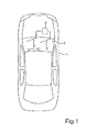
- An in Fig. 1 illustrated motor vehicle 1 is for example a passenger car.
- a rain sensor 3 is mounted, which is designed to detect the intensity of a precipitate on the windshield 2.
- the rain sensor 3 is electrically coupled to a control unit 4, by means of which windshield wipers 5, 6 are driven to wipe the windshield 2.
- the control unit 4 controls the frequency and / or the speed of movement of the windshield wipers 5, 6 as a function of the detected intensity of the precipitation.
- the rain sensor 3 includes a plurality of transmitting elements and a receiving element.
- the transmitting elements and the receiving element can be identical elements, namely preferably photodiodes or light-emitting diodes, which can emit electromagnetic radiation in the ultraviolet spectral range. But it can be chosen a different frequency of the radiation.
- the sensor 3 is attached to the windshield 2 via an adhesive layer, for example.
- the sensor 3 may also be hidden behind a housing of a rearview mirror, i. between the disc 2 and the housing.
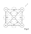
- the rain sensor 3 includes in the exemplary embodiment exactly four transmitting elements D1 to D4 and a single receiving element D5, which is operated exclusively as a receiver.
- the transmitting elements D2, D3 are additionally used or operated as radiation receivers, so that the two transmitting elements D2, D3 are used both as transmitters and as receivers in inverted mode.
- the transmitting elements D1 to D4 is in each case a lens or another optic, which is designed so that the focusing takes place in each case in several directions.
- focusing takes place in three directions. Rays emitted by the transmitting element D1 are focused both in the direction via the windshield 2 to the receiving element D5 and to the transmitting elements D2, D3. The same applies to the other transmission elements D2 to D4.
- Fig. 2 are shown with M1 to M4 measuring fields, which represent areas of the windshield 2, where the emitted rays are to be reflected.
- Each measuring field M1 to M4 thus means a separate measuring path, which are given as a radiation receiver due to the use of at least some of the transmitting elements D1 to D4. If, for example, transmitted by the transmitting element D1, then a first measuring path from the element D1 to the receiving element D5 is given, a second measuring path is given from D1 to D3, and a third measuring path is given from D1 to D2 Measuring distances, with only four transmission elements D1 to D4 and a single receiving element D5.
- the transmitting elements D1 to D4 are distributed in a square shape around the receiving element D5. They are equidistant to each other and also arranged equidistant from the receiving element D5, so that on the one hand the distances between the adjacent transmitting elements D1 to D4 are the same and on the other hand, the respective distances between the transmitting elements D1 to D4 on the one hand and the receiving element D5 on the other are the same.
- the transmitting elements D1 to D4 are thus at respective corners of a square, in the middle of which the receiving element D5 is located.
- the transmitting elements D1 and D4 lie on a common diagonal, and also the transmitting elements D2 and D3 are on a common diagonal.
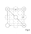
- the first and the fourth transmitting element D1, D4 activated for simultaneous emission of the beams.
- the third transmitting element D3 is operated as a radiation receiver.
- the element D3 thus simultaneously receives the rays of D1 and the rays of D4.
- a renewed activation of the transmission elements D1 and D4 which once again emit the beams simultaneously.
- the transmitting element D2 is operated as a radiation receiver.
- the two in the Fig. 5 and 6 designated measuring sections M3 and M4 are then compared. This means that the received by the transmitting element D3 rays are compared with the rays which have been received by the transmitting element D2. Depending on this comparison, the windshield wipers 5, 6 are activated.
- the measuring cycle described above is repeated periodically, in particular in such a way that the intensity of the precipitation is detected continuously or continuously.
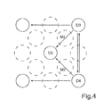
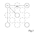
- the first transmitting element D1 is driven to emit the beams, while the third element D3 is operated as a receiver.
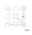
- only one measuring section M3a is used. Time offset to this is done in a subsequent step according to Fig. 8 a control of the transmitting element D4, which emits the beams.
- the third transmitting element D3 is operated as a receiver.
- the measuring section M3b is used. The two in the Fig. 7 and 8th The measured distances M3a and M3b can be compared with each other by comparing the intensity of the rays of D1 with the intensity of the rays of D4. Depending on this comparison, the control of the windshield wipers 5, 6 then takes place.
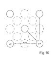
- a further step according to Fig. 9 again the first transmitting element D1 are driven to emit the beams, while now the second element D2 is operated as a receiver.
- a measuring section M4a between D1 and D2 is used. Time offset to then takes place in a further step according to Fig. 10 the control of the fourth transmitting element D4, wherein as the receiver further the second element D2 is operated.
- a measuring section M4b between D4 and D2 is used.
- the measuring sections M4a according to Fig. 9 and M4b according to Fig. 10 are compared by comparing the beams of D1 on the one hand and D4 received on the other hand by the second element D2 on the other hand.
Landscapes
- Engineering & Computer Science (AREA)
- Automation & Control Theory (AREA)
- Mechanical Engineering (AREA)
- Investigating Or Analysing Materials By Optical Means (AREA)
Applications Claiming Priority (1)
| Application Number | Priority Date | Filing Date | Title |
|---|---|---|---|
| DE102012019621.0A DE102012019621A1 (de) | 2012-10-06 | 2012-10-06 | Regensensor, Kraftfahrzeug und Verfahren zum Erfassen der Intensität eines Niederschlags |
Publications (1)
| Publication Number | Publication Date |
|---|---|
| EP2716511A2 true EP2716511A2 (fr) | 2014-04-09 |
Family
ID=49382211
Family Applications (1)
| Application Number | Title | Priority Date | Filing Date |
|---|---|---|---|
| EP20130187610 Withdrawn EP2716511A2 (fr) | 2012-10-06 | 2013-10-07 | Capteur de pluie, véhicule automobile et procédé de détection de l'intensité d'une précipitation |
Country Status (2)
| Country | Link |
|---|---|
| EP (1) | EP2716511A2 (fr) |
| DE (1) | DE102012019621A1 (fr) |
Cited By (1)
| Publication number | Priority date | Publication date | Assignee | Title |
|---|---|---|---|---|
| EP3535564A4 (fr) * | 2016-11-07 | 2020-07-08 | Littelfuse, Inc. | Module de détection de rayonnement solaire et de pluie intégré |
Families Citing this family (2)
| Publication number | Priority date | Publication date | Assignee | Title |
|---|---|---|---|---|
| DE102015121899B4 (de) | 2015-12-16 | 2023-03-23 | Valeo Schalter Und Sensoren Gmbh | Sensorvorrichtung mit einem Regensensor, und Kraftfahrzeug |
| DE102018123559A1 (de) * | 2018-09-25 | 2020-03-26 | Osram Opto Semiconductors Gmbh | Sensorvorrichtung |
Citations (1)
| Publication number | Priority date | Publication date | Assignee | Title |
|---|---|---|---|---|
| EP1187743B1 (fr) | 1999-06-18 | 2007-05-02 | Valeo Wischersysteme GmbH | Detecteur de pluie servant a detecter des gouttes d'humidite |
Family Cites Families (6)
| Publication number | Priority date | Publication date | Assignee | Title |
|---|---|---|---|---|
| FR2396419A1 (fr) * | 1977-06-27 | 1979-01-26 | Thomson Csf | Diode capable de fonctionner en emetteur et detecteur de lumiere de la meme longueur d'onde alternativement |
| FR2648096B1 (fr) * | 1989-06-12 | 1991-08-23 | Valeo Systemes Dessuyage | Systeme d'essuie-glace avec detecteur de pluie |
| DE19725287A1 (de) * | 1997-06-14 | 1998-12-17 | Itt Mfg Enterprises Inc | Regensensor mit gebondeten Sensor-Chips |
| DE19933641A1 (de) * | 1999-07-17 | 2001-03-08 | Bosch Gmbh Robert | Sensoreinrichtung zur Erfassung einer Benetzung auf einer Scheibe |
| DE102006044792A1 (de) * | 2006-09-13 | 2008-03-27 | Schefenacker Vision Systems Germany Gmbh | Sensor zur Detektion von Schmutz und/oder Regen und Verfahren zum Betreiben eines Sensors |
| DE102007061725A1 (de) * | 2007-12-20 | 2009-06-25 | Robert Bosch Gmbh | Verfahren zur Plausibilitätsprüfung wenigstens eines Lichtdetektors einer Fahrlichtassistenzvorrichtung eines Kraftfahrzeugs |
-
2012
- 2012-10-06 DE DE102012019621.0A patent/DE102012019621A1/de active Pending
-
2013
- 2013-10-07 EP EP20130187610 patent/EP2716511A2/fr not_active Withdrawn
Patent Citations (1)
| Publication number | Priority date | Publication date | Assignee | Title |
|---|---|---|---|---|
| EP1187743B1 (fr) | 1999-06-18 | 2007-05-02 | Valeo Wischersysteme GmbH | Detecteur de pluie servant a detecter des gouttes d'humidite |
Cited By (1)
| Publication number | Priority date | Publication date | Assignee | Title |
|---|---|---|---|---|
| EP3535564A4 (fr) * | 2016-11-07 | 2020-07-08 | Littelfuse, Inc. | Module de détection de rayonnement solaire et de pluie intégré |
Also Published As
| Publication number | Publication date |
|---|---|
| DE102012019621A1 (de) | 2014-04-10 |
Similar Documents
| Publication | Publication Date | Title |
|---|---|---|
| EP0981470B2 (fr) | Capteur optique | |
| WO2011007015A1 (fr) | Procédé à laser permettant la classification de coefficients de frottement dans des véhicules automobiles | |
| DE102018121454A1 (de) | Anzeigevorrichtung mit Beschlagserkennungseinrichtung und Verfahren zum Betreiben einer Beschlagserkennung, ein Außenspiegel sowie ein Kraftfahrzeug | |
| DE102010025719A1 (de) | Vorrichtung und Verfahren zur Ausgabe eines Signals bei gefährlichem Untergrund unter einem Fahrzeug | |
| DE102010026564A1 (de) | Verfahren und Sensoranordnung zum Detektieren der Sichtverhältnisse außerhalb eines Kraftfahrzeuges | |
| DE10152998A1 (de) | Sensoreinheit zur Detektion einer Benetzung einer Scheibe | |
| DE3735267A1 (de) | Vorrichtung zur sichtweitenmessung | |
| WO2012107136A1 (fr) | Procédé et dispositif pour déterminer la transparence d'une vitre d'un véhicule | |
| EP2583082B1 (fr) | Capteur pour la détermination, sans contact, des conditions de la chaussée, et son utilisation | |
| DE19526249A1 (de) | Vorrichtung zur Erfassung von Wasser oder dergleichen auf einer Fensterscheibe eines Kraftfahrzeuges | |
| DE102011015527A1 (de) | Sensor zur berührungslosen Bestimmung der Fahrbahnbeschaffenheit und dessen Verwendung | |
| WO2017097654A1 (fr) | Procédé de détection d'un dysfonctionnement d'un dispositif de balayage laser, dispositif de balayage laser et véhicule à moteur | |
| DE102012025467A1 (de) | Optoelektronische Sensoreinrichtung zur Bestimmung eines Reflexionsvermögens unter Berücksichtigung von Intensitätsverlusten, Kraftfahrzeug und entsprechendes Verfahren | |
| EP2716511A2 (fr) | Capteur de pluie, véhicule automobile et procédé de détection de l'intensité d'une précipitation | |
| DE102004033944A1 (de) | Vorrichtung und Verfahren zur Überprüfung der Betriebsvorraussetzungen einer optischen Sensoranordnung in einem Fahrzeug | |
| DE10341622B3 (de) | Anzeigeeinrichtung mit kombiniertem Lichtleiter | |
| DE3825665A1 (de) | Sensorvorrichtung zur feststellung des vorhandenseins von wassertroepfchen auf einer fahrzeug-scheibe und mit der sensorvorrichtung arbeitendes scheibenwischer-steuergeraet | |
| DE102008037266A1 (de) | Reinigungssystem für Fahrzeugscheinwerfer | |
| DE102018105657B3 (de) | Rückblicksensoranordnung und fahrzeug | |
| DE102010023532A1 (de) | Kamerasystem für Fahrzeuganwendungen | |
| WO2002004248A1 (fr) | Dispositif et procede permettant l'adaptation automatique d'un systeme de detection lumineuse a un pare-brise | |
| DE10132454A1 (de) | Sensoreinheit zum automatischen Schalten von Beleuchtungseinrichtungen sowie Koppelmedium für eine Sensoreinheit | |
| DE102016120969B4 (de) | Nebelsensor mit Reflexionsanalyse | |
| DE102010025705A1 (de) | Verfahren und Vorrichtung zur Warnung anderer Verkehrsteilnehmer vor gefährlichen Fahrbahnbeschaffenheiten oder Fahrbahnzuständen | |
| EP1925476B1 (fr) | Procédé et système de commande d'une climatisation dans un véhicule automobile |
Legal Events
| Date | Code | Title | Description |
|---|---|---|---|
| PUAI | Public reference made under article 153(3) epc to a published international application that has entered the european phase |
Free format text: ORIGINAL CODE: 0009012 |
|
| AK | Designated contracting states |
Kind code of ref document: A2 Designated state(s): AL AT BE BG CH CY CZ DE DK EE ES FI FR GB GR HR HU IE IS IT LI LT LU LV MC MK MT NL NO PL PT RO RS SE SI SK SM TR |
|
| AX | Request for extension of the european patent |
Extension state: BA ME |
|
| RIN1 | Information on inventor provided before grant (corrected) |
Inventor name: BRIEM, ROLF |
|
| STAA | Information on the status of an ep patent application or granted ep patent |
Free format text: STATUS: THE APPLICATION IS DEEMED TO BE WITHDRAWN |
|
| 18D | Application deemed to be withdrawn |
Effective date: 20180501 |