EP2716352A1 - Dispositif générateur de microbulles, procédé associé, et procédé de réaction gaz-liquide l'utilisant - Google Patents
Dispositif générateur de microbulles, procédé associé, et procédé de réaction gaz-liquide l'utilisant Download PDFInfo
- Publication number
- EP2716352A1 EP2716352A1 EP11866490.3A EP11866490A EP2716352A1 EP 2716352 A1 EP2716352 A1 EP 2716352A1 EP 11866490 A EP11866490 A EP 11866490A EP 2716352 A1 EP2716352 A1 EP 2716352A1
- Authority
- EP
- European Patent Office
- Prior art keywords
- fluid
- processing
- gas
- processed
- processing surfaces
- Prior art date
- Legal status (The legal status is an assumption and is not a legal conclusion. Google has not performed a legal analysis and makes no representation as to the accuracy of the status listed.)
- Withdrawn
Links
- 239000007788 liquid Substances 0.000 title claims abstract description 72
- 238000000034 method Methods 0.000 title claims abstract description 37
- 238000006243 chemical reaction Methods 0.000 title claims description 34
- 238000012545 processing Methods 0.000 claims abstract description 257
- 239000012530 fluid Substances 0.000 claims abstract description 219
- 239000000376 reactant Substances 0.000 claims description 27
- 238000013459 approach Methods 0.000 claims description 23
- 239000010409 thin film Substances 0.000 claims description 20
- 238000002156 mixing Methods 0.000 claims description 14
- 239000007789 gas Substances 0.000 description 52
- UIIMBOGNXHQVGW-UHFFFAOYSA-M Sodium bicarbonate Chemical compound [Na+].OC([O-])=O UIIMBOGNXHQVGW-UHFFFAOYSA-M 0.000 description 24
- 230000007246 mechanism Effects 0.000 description 24
- CURLTUGMZLYLDI-UHFFFAOYSA-N Carbon dioxide Chemical compound O=C=O CURLTUGMZLYLDI-UHFFFAOYSA-N 0.000 description 19
- HEMHJVSKTPXQMS-UHFFFAOYSA-M Sodium hydroxide Chemical compound [OH-].[Na+] HEMHJVSKTPXQMS-UHFFFAOYSA-M 0.000 description 18
- 230000001276 controlling effect Effects 0.000 description 15
- 238000000926 separation method Methods 0.000 description 13
- CDBYLPFSWZWCQE-UHFFFAOYSA-L Sodium Carbonate Chemical compound [Na+].[Na+].[O-]C([O-])=O CDBYLPFSWZWCQE-UHFFFAOYSA-L 0.000 description 12
- 229910000030 sodium bicarbonate Inorganic materials 0.000 description 12
- 235000017557 sodium bicarbonate Nutrition 0.000 description 12
- 239000002904 solvent Substances 0.000 description 12
- IJGRMHOSHXDMSA-UHFFFAOYSA-N Atomic nitrogen Chemical compound N#N IJGRMHOSHXDMSA-UHFFFAOYSA-N 0.000 description 11
- -1 alcohol compound Chemical class 0.000 description 10
- 229910002092 carbon dioxide Inorganic materials 0.000 description 9
- 239000001569 carbon dioxide Substances 0.000 description 9
- 229910001873 dinitrogen Inorganic materials 0.000 description 7
- 239000000463 material Substances 0.000 description 7
- 239000000126 substance Substances 0.000 description 7
- 229910052751 metal Inorganic materials 0.000 description 6
- 239000002184 metal Substances 0.000 description 6
- 229910000029 sodium carbonate Inorganic materials 0.000 description 6
- MWUXSHHQAYIFBG-UHFFFAOYSA-N Nitric oxide Chemical compound O=[N] MWUXSHHQAYIFBG-UHFFFAOYSA-N 0.000 description 5
- 239000011859 microparticle Substances 0.000 description 5
- 239000002245 particle Substances 0.000 description 5
- XLYOFNOQVPJJNP-UHFFFAOYSA-N water Substances O XLYOFNOQVPJJNP-UHFFFAOYSA-N 0.000 description 5
- DBMJMQXJHONAFJ-UHFFFAOYSA-M Sodium laurylsulphate Chemical compound [Na+].CCCCCCCCCCCCOS([O-])(=O)=O DBMJMQXJHONAFJ-UHFFFAOYSA-M 0.000 description 4
- 230000000694 effects Effects 0.000 description 4
- 235000019333 sodium laurylsulphate Nutrition 0.000 description 4
- 238000002425 crystallisation Methods 0.000 description 3
- 230000008025 crystallization Effects 0.000 description 3
- 239000006185 dispersion Substances 0.000 description 3
- 230000007613 environmental effect Effects 0.000 description 3
- 239000010408 film Substances 0.000 description 3
- 239000000203 mixture Substances 0.000 description 3
- 239000007787 solid Substances 0.000 description 3
- XKRFYHLGVUSROY-UHFFFAOYSA-N Argon Chemical compound [Ar] XKRFYHLGVUSROY-UHFFFAOYSA-N 0.000 description 2
- BVKZGUZCCUSVTD-UHFFFAOYSA-L Carbonate Chemical compound [O-]C([O-])=O BVKZGUZCCUSVTD-UHFFFAOYSA-L 0.000 description 2
- VEXZGXHMUGYJMC-UHFFFAOYSA-N Hydrochloric acid Chemical compound Cl VEXZGXHMUGYJMC-UHFFFAOYSA-N 0.000 description 2
- RAHZWNYVWXNFOC-UHFFFAOYSA-N Sulphur dioxide Chemical compound O=S=O RAHZWNYVWXNFOC-UHFFFAOYSA-N 0.000 description 2
- 239000000919 ceramic Substances 0.000 description 2
- 230000000052 comparative effect Effects 0.000 description 2
- 150000001875 compounds Chemical class 0.000 description 2
- 238000007796 conventional method Methods 0.000 description 2
- 238000001816 cooling Methods 0.000 description 2
- 239000002270 dispersing agent Substances 0.000 description 2
- 238000010438 heat treatment Methods 0.000 description 2
- 229910000041 hydrogen chloride Inorganic materials 0.000 description 2
- IXCSERBJSXMMFS-UHFFFAOYSA-N hydrogen chloride Substances Cl.Cl IXCSERBJSXMMFS-UHFFFAOYSA-N 0.000 description 2
- XLYOFNOQVPJJNP-UHFFFAOYSA-M hydroxide Chemical compound [OH-] XLYOFNOQVPJJNP-UHFFFAOYSA-M 0.000 description 2
- 238000004519 manufacturing process Methods 0.000 description 2
- 229910052757 nitrogen Inorganic materials 0.000 description 2
- 229910052755 nonmetal Inorganic materials 0.000 description 2
- 239000003960 organic solvent Substances 0.000 description 2
- 239000000049 pigment Substances 0.000 description 2
- 230000008569 process Effects 0.000 description 2
- 230000036632 reaction speed Effects 0.000 description 2
- 230000001105 regulatory effect Effects 0.000 description 2
- 239000011347 resin Substances 0.000 description 2
- 229920005989 resin Polymers 0.000 description 2
- 150000003839 salts Chemical class 0.000 description 2
- 230000007480 spreading Effects 0.000 description 2
- 238000003756 stirring Methods 0.000 description 2
- MGWGWNFMUOTEHG-UHFFFAOYSA-N 4-(3,5-dimethylphenyl)-1,3-thiazol-2-amine Chemical compound CC1=CC(C)=CC(C=2N=C(N)SC=2)=C1 MGWGWNFMUOTEHG-UHFFFAOYSA-N 0.000 description 1
- OKTJSMMVPCPJKN-UHFFFAOYSA-N Carbon Chemical compound [C] OKTJSMMVPCPJKN-UHFFFAOYSA-N 0.000 description 1
- UGFAIRIUMAVXCW-UHFFFAOYSA-N Carbon monoxide Chemical compound [O+]#[C-] UGFAIRIUMAVXCW-UHFFFAOYSA-N 0.000 description 1
- ZAMOUSCENKQFHK-UHFFFAOYSA-N Chlorine atom Chemical compound [Cl] ZAMOUSCENKQFHK-UHFFFAOYSA-N 0.000 description 1
- 229910000831 Steel Inorganic materials 0.000 description 1
- 241000700605 Viruses Species 0.000 description 1
- 238000005299 abrasion Methods 0.000 description 1
- 230000009471 action Effects 0.000 description 1
- 150000007824 aliphatic compounds Chemical class 0.000 description 1
- HSFWRNGVRCDJHI-UHFFFAOYSA-N alpha-acetylene Natural products C#C HSFWRNGVRCDJHI-UHFFFAOYSA-N 0.000 description 1
- 229910052786 argon Inorganic materials 0.000 description 1
- 150000001491 aromatic compounds Chemical class 0.000 description 1
- 230000001174 ascending effect Effects 0.000 description 1
- QVGXLLKOCUKJST-UHFFFAOYSA-N atomic oxygen Chemical compound [O] QVGXLLKOCUKJST-UHFFFAOYSA-N 0.000 description 1
- 229920001400 block copolymer Polymers 0.000 description 1
- 239000000872 buffer Substances 0.000 description 1
- 229910052799 carbon Inorganic materials 0.000 description 1
- QGJOPFRUJISHPQ-NJFSPNSNSA-N carbon disulfide-14c Chemical compound S=[14C]=S QGJOPFRUJISHPQ-NJFSPNSNSA-N 0.000 description 1
- 229910002091 carbon monoxide Inorganic materials 0.000 description 1
- 229910002090 carbon oxide Inorganic materials 0.000 description 1
- 239000000460 chlorine Substances 0.000 description 1
- 229910052801 chlorine Inorganic materials 0.000 description 1
- 239000011248 coating agent Substances 0.000 description 1
- 238000000576 coating method Methods 0.000 description 1
- 239000002872 contrast media Substances 0.000 description 1
- 230000008021 deposition Effects 0.000 description 1
- 238000000151 deposition Methods 0.000 description 1
- 238000004945 emulsification Methods 0.000 description 1
- 239000000839 emulsion Substances 0.000 description 1
- RTZKZFJDLAIYFH-UHFFFAOYSA-N ether Substances CCOCC RTZKZFJDLAIYFH-UHFFFAOYSA-N 0.000 description 1
- 125000002534 ethynyl group Chemical group [H]C#C* 0.000 description 1
- 230000005484 gravity Effects 0.000 description 1
- 150000002366 halogen compounds Chemical class 0.000 description 1
- 230000036541 health Effects 0.000 description 1
- 239000001307 helium Substances 0.000 description 1
- 229910052734 helium Inorganic materials 0.000 description 1
- SWQJXJOGLNCZEY-UHFFFAOYSA-N helium atom Chemical compound [He] SWQJXJOGLNCZEY-UHFFFAOYSA-N 0.000 description 1
- 239000001257 hydrogen Substances 0.000 description 1
- 229910052739 hydrogen Inorganic materials 0.000 description 1
- 125000004435 hydrogen atom Chemical class [H]* 0.000 description 1
- 229910017053 inorganic salt Inorganic materials 0.000 description 1
- 239000002608 ionic liquid Substances 0.000 description 1
- 238000005259 measurement Methods 0.000 description 1
- 238000000691 measurement method Methods 0.000 description 1
- 239000012046 mixed solvent Substances 0.000 description 1
- 239000002101 nanobubble Substances 0.000 description 1
- 150000004767 nitrides Chemical class 0.000 description 1
- JCXJVPUVTGWSNB-UHFFFAOYSA-N nitrogen dioxide Inorganic materials O=[N]=O JCXJVPUVTGWSNB-UHFFFAOYSA-N 0.000 description 1
- 239000003921 oil Substances 0.000 description 1
- 150000002894 organic compounds Chemical class 0.000 description 1
- 239000001301 oxygen Substances 0.000 description 1
- 229910052760 oxygen Inorganic materials 0.000 description 1
- 230000002093 peripheral effect Effects 0.000 description 1
- 229910052698 phosphorus Inorganic materials 0.000 description 1
- 238000007747 plating Methods 0.000 description 1
- 229920000642 polymer Polymers 0.000 description 1
- 238000005381 potential energy Methods 0.000 description 1
- 238000001556 precipitation Methods 0.000 description 1
- 238000003672 processing method Methods 0.000 description 1
- 102000004169 proteins and genes Human genes 0.000 description 1
- 108090000623 proteins and genes Proteins 0.000 description 1
- 239000002994 raw material Substances 0.000 description 1
- 230000009257 reactivity Effects 0.000 description 1
- 230000009467 reduction Effects 0.000 description 1
- 238000005067 remediation Methods 0.000 description 1
- 230000000630 rising effect Effects 0.000 description 1
- 229910052594 sapphire Inorganic materials 0.000 description 1
- 239000010980 sapphire Substances 0.000 description 1
- 150000003377 silicon compounds Chemical class 0.000 description 1
- 229940083575 sodium dodecyl sulfate Drugs 0.000 description 1
- 239000002689 soil Substances 0.000 description 1
- 239000007921 spray Substances 0.000 description 1
- 239000010959 steel Substances 0.000 description 1
- 230000003746 surface roughness Effects 0.000 description 1
- 239000004094 surface-active agent Substances 0.000 description 1
- 239000008399 tap water Substances 0.000 description 1
- 235000020679 tap water Nutrition 0.000 description 1
- 229910021642 ultra pure water Inorganic materials 0.000 description 1
- 239000012498 ultrapure water Substances 0.000 description 1
- 238000011144 upstream manufacturing Methods 0.000 description 1
- 238000004065 wastewater treatment Methods 0.000 description 1
Images


Classifications
-
- B—PERFORMING OPERATIONS; TRANSPORTING
- B01—PHYSICAL OR CHEMICAL PROCESSES OR APPARATUS IN GENERAL
- B01F—MIXING, e.g. DISSOLVING, EMULSIFYING OR DISPERSING
- B01F23/00—Mixing according to the phases to be mixed, e.g. dispersing or emulsifying
- B01F23/20—Mixing gases with liquids
- B01F23/23—Mixing gases with liquids by introducing gases into liquid media, e.g. for producing aerated liquids
- B01F23/233—Mixing gases with liquids by introducing gases into liquid media, e.g. for producing aerated liquids using driven stirrers with completely immersed stirring elements
-
- B—PERFORMING OPERATIONS; TRANSPORTING
- B01—PHYSICAL OR CHEMICAL PROCESSES OR APPARATUS IN GENERAL
- B01F—MIXING, e.g. DISSOLVING, EMULSIFYING OR DISPERSING
- B01F23/00—Mixing according to the phases to be mixed, e.g. dispersing or emulsifying
- B01F23/20—Mixing gases with liquids
-
- B—PERFORMING OPERATIONS; TRANSPORTING
- B01—PHYSICAL OR CHEMICAL PROCESSES OR APPARATUS IN GENERAL
- B01F—MIXING, e.g. DISSOLVING, EMULSIFYING OR DISPERSING
- B01F23/00—Mixing according to the phases to be mixed, e.g. dispersing or emulsifying
- B01F23/20—Mixing gases with liquids
- B01F23/23—Mixing gases with liquids by introducing gases into liquid media, e.g. for producing aerated liquids
- B01F23/231—Mixing gases with liquids by introducing gases into liquid media, e.g. for producing aerated liquids by bubbling
-
- B—PERFORMING OPERATIONS; TRANSPORTING
- B01—PHYSICAL OR CHEMICAL PROCESSES OR APPARATUS IN GENERAL
- B01F—MIXING, e.g. DISSOLVING, EMULSIFYING OR DISPERSING
- B01F23/00—Mixing according to the phases to be mixed, e.g. dispersing or emulsifying
-
- B—PERFORMING OPERATIONS; TRANSPORTING
- B01—PHYSICAL OR CHEMICAL PROCESSES OR APPARATUS IN GENERAL
- B01F—MIXING, e.g. DISSOLVING, EMULSIFYING OR DISPERSING
- B01F23/00—Mixing according to the phases to be mixed, e.g. dispersing or emulsifying
- B01F23/20—Mixing gases with liquids
- B01F23/23—Mixing gases with liquids by introducing gases into liquid media, e.g. for producing aerated liquids
- B01F23/2319—Methods of introducing gases into liquid media
-
- B—PERFORMING OPERATIONS; TRANSPORTING
- B01—PHYSICAL OR CHEMICAL PROCESSES OR APPARATUS IN GENERAL
- B01F—MIXING, e.g. DISSOLVING, EMULSIFYING OR DISPERSING
- B01F23/00—Mixing according to the phases to be mixed, e.g. dispersing or emulsifying
- B01F23/20—Mixing gases with liquids
- B01F23/23—Mixing gases with liquids by introducing gases into liquid media, e.g. for producing aerated liquids
- B01F23/237—Mixing gases with liquids by introducing gases into liquid media, e.g. for producing aerated liquids characterised by the physical or chemical properties of gases or vapours introduced in the liquid media
- B01F23/2373—Mixing gases with liquids by introducing gases into liquid media, e.g. for producing aerated liquids characterised by the physical or chemical properties of gases or vapours introduced in the liquid media for obtaining fine bubbles, i.e. bubbles with a size below 100 µm
-
- B—PERFORMING OPERATIONS; TRANSPORTING
- B01—PHYSICAL OR CHEMICAL PROCESSES OR APPARATUS IN GENERAL
- B01F—MIXING, e.g. DISSOLVING, EMULSIFYING OR DISPERSING
- B01F25/00—Flow mixers; Mixers for falling materials, e.g. solid particles
-
- B—PERFORMING OPERATIONS; TRANSPORTING
- B01—PHYSICAL OR CHEMICAL PROCESSES OR APPARATUS IN GENERAL
- B01F—MIXING, e.g. DISSOLVING, EMULSIFYING OR DISPERSING
- B01F25/00—Flow mixers; Mixers for falling materials, e.g. solid particles
- B01F25/70—Spray-mixers, e.g. for mixing intersecting sheets of material
- B01F25/74—Spray-mixers, e.g. for mixing intersecting sheets of material with rotating parts, e.g. discs
-
- B—PERFORMING OPERATIONS; TRANSPORTING
- B01—PHYSICAL OR CHEMICAL PROCESSES OR APPARATUS IN GENERAL
- B01F—MIXING, e.g. DISSOLVING, EMULSIFYING OR DISPERSING
- B01F27/00—Mixers with rotary stirring devices in fixed receptacles; Kneaders
-
- B—PERFORMING OPERATIONS; TRANSPORTING
- B01—PHYSICAL OR CHEMICAL PROCESSES OR APPARATUS IN GENERAL
- B01F—MIXING, e.g. DISSOLVING, EMULSIFYING OR DISPERSING
- B01F27/00—Mixers with rotary stirring devices in fixed receptacles; Kneaders
- B01F27/27—Mixers with stator-rotor systems, e.g. with intermeshing teeth or cylinders or having orifices
- B01F27/271—Mixers with stator-rotor systems, e.g. with intermeshing teeth or cylinders or having orifices with means for moving the materials to be mixed radially between the surfaces of the rotor and the stator
- B01F27/2712—Mixers with stator-rotor systems, e.g. with intermeshing teeth or cylinders or having orifices with means for moving the materials to be mixed radially between the surfaces of the rotor and the stator provided with ribs, ridges or grooves on one surface
-
- B—PERFORMING OPERATIONS; TRANSPORTING
- B01—PHYSICAL OR CHEMICAL PROCESSES OR APPARATUS IN GENERAL
- B01F—MIXING, e.g. DISSOLVING, EMULSIFYING OR DISPERSING
- B01F27/00—Mixers with rotary stirring devices in fixed receptacles; Kneaders
- B01F27/27—Mixers with stator-rotor systems, e.g. with intermeshing teeth or cylinders or having orifices
- B01F27/271—Mixers with stator-rotor systems, e.g. with intermeshing teeth or cylinders or having orifices with means for moving the materials to be mixed radially between the surfaces of the rotor and the stator
- B01F27/2714—Mixers with stator-rotor systems, e.g. with intermeshing teeth or cylinders or having orifices with means for moving the materials to be mixed radially between the surfaces of the rotor and the stator the relative position of the stator and the rotor, gap in between or gap with the walls being adjustable
-
- B—PERFORMING OPERATIONS; TRANSPORTING
- B01—PHYSICAL OR CHEMICAL PROCESSES OR APPARATUS IN GENERAL
- B01F—MIXING, e.g. DISSOLVING, EMULSIFYING OR DISPERSING
- B01F27/00—Mixers with rotary stirring devices in fixed receptacles; Kneaders
- B01F27/80—Mixers with rotary stirring devices in fixed receptacles; Kneaders with stirrers rotating about a substantially vertical axis
- B01F27/93—Mixers with rotary stirring devices in fixed receptacles; Kneaders with stirrers rotating about a substantially vertical axis with rotary discs
-
- B—PERFORMING OPERATIONS; TRANSPORTING
- B01—PHYSICAL OR CHEMICAL PROCESSES OR APPARATUS IN GENERAL
- B01J—CHEMICAL OR PHYSICAL PROCESSES, e.g. CATALYSIS OR COLLOID CHEMISTRY; THEIR RELEVANT APPARATUS
- B01J19/00—Chemical, physical or physico-chemical processes in general; Their relevant apparatus
- B01J19/18—Stationary reactors having moving elements inside
- B01J19/1887—Stationary reactors having moving elements inside forming a thin film
-
- C—CHEMISTRY; METALLURGY
- C01—INORGANIC CHEMISTRY
- C01D—COMPOUNDS OF ALKALI METALS, i.e. LITHIUM, SODIUM, POTASSIUM, RUBIDIUM, CAESIUM, OR FRANCIUM
- C01D7/00—Carbonates of sodium, potassium or alkali metals in general
- C01D7/07—Preparation from the hydroxides
Definitions
- the present invention relates to: an apparatus for generating fine bubbles between processing surfaces in processing members capable of approaching to and separating from each other, at least one of which rotates relative to the other; and a method for generating the fine bubbles.
- the present invention relates to a method for a gas-liquid reaction characterized in that the gas-liquid reaction is executed by contacting the fine bubbles generated between the processing surfaces with a reactant.
- fine bubbles such as microbubbles and nanobubbles are receiving an attention as they are used in a wide range of fields including an environmental field, an industrial field, a health field, and a medical field, and thus, are used for culture fishery, waste-water treatment, soil remediation, reduction of fluid resistance in the ship bottom, sanitation, contrast agent, and so on.
- the present invention has an object to provide an apparatus for generating fine bubbles and a method for generating fine bubbles by applying a fluid processing apparatus to process a substance to be processed between a plurality of processing surfaces in a plurality of processing members which are disposed in a position they are faced with each other so as to be able to approach to and separate from each other, at least one of which rotates relative to the other. Furthermore, because the generated fine bubbles have a large interfacial area, an object thereof is to provide a method for an efficient gas-liquid reaction by effectively contacting the generated fine bubbles with a reactant between the processing surfaces.
- the invention provides an apparatus for generating fine bubbles, characterized in that the apparatus is provided with a plurality of processing members which are disposed in a position they are faced with each other so as to be able to approach to and separate from each other, at least one of which rotates relative to the other, a plurality of processing surfaces which are disposed in a position they are faced each other in the respective plurality of processing members, and at least two independent flow paths leading to the said plurality of processing surfaces, whereby introducing a fluid to be processed into the plurality of processing surfaces through the at least two independent flow paths to carry out fluid processing, characterized in that of the at least two independent flow paths, introducing a liquid which is one fluid to be processed through one flow path, while introducing a gas which is another fluid to be processed through another flow path, whereby generating bubbles between the plurality of processing surfaces.
- the invention according to the second claim of the present application provides a method for generating fine bubbles, characterized in that fine bubbles are generated by mixing a liquid and a gas as fluids to be processed in a plurality of processing members which are disposed in a position they are faced with each other so as to be able to approach to and separate from each other , at least one of which rotates relative to the other, and in between a plurality of processing surfaces which are disposed in a position they are faced with each other in the each of the plurality of processing members; characterized in that, any one of the liquid and the gas passes through between the plurality of processing surfaces while forming a thin film fluid, an another introduction path independent of the flow path for the any one of the liquid and the gas is provided, at least any one of the plurality of processing surfaces is arranged with one opening which leads to this introduction path, any other one of the liquid and the gas is introduced between the processing surfaces through the opening, whereby mixing the liquid with the gas in the thin film fluid to generate fine bubbles.
- the invention according to the third claim of the present application provides a method for gas-liquid reaction, characterized in that the method for generating fine bubbles according to the second claim is used, characterized in that at least one reactant is contained in at least any one of the fluids to be processed, i.e., in at least any one of the liquid, the gas, and one fluid to be processed other than the said liquid and the said gas, characterized in that the fluids to be processed are mixed in the thin fluid thereby reacting the gas with the reactant.
- the invention according to the fourth claim provides a method for a gas-liquid reaction, characterized by using the method for generating fine bubbles according to the second claim, the fine bubbles generated in the thin film fluid formed between the plurality of processing surfaces is contacted in the processing surfaces with a reactant contained in at least any one of the fluids to be processed, i.e., in at least any one of the liquid, the gas, and one fluid to be processed other than the said liquid and the said gas, these being introduced into between the plurality of the processing surfaces to generate the fine bubbles, whereby reacting the fine gas bubbles with the reactant.
- an apparatus for generating fine bubbles between a plurality of processing surfaces in a plurality of processing members which are disposed in a position they are faced with each other so as to be able to approach to and separate from each other, at least one of which rotates relative to the other; and a method for generating fine bubbles.
- fine bubbles can be generated more easily as compared with a conventional method.
- a gas-liquid reaction can be executed more efficiently than ever because the generated fine bubbles can be contacted with a reactant efficiently and effectively.
- FIG. 1 is a schematic sectional view showing the fine bubble-generating apparatus according to an embodiment of the present invention.
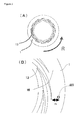
- FIG. 2(A) is a schematic plane view of the first processing surface in the fine bubble-generating apparatus shown in FIG. 1
- FIG. 2(B) is an enlarged view showing an important part of the processing surface in the apparatus.
- FIG. 3(A) is a sectional view of the second introduction member of the apparatus
- FIG. 3(B) is an enlarged view showing an important part of the processing surface for explaining the second introduction member.
- the fluid processing apparatus shown in FIG. 1 to FIG. 3 is similar to the apparatus described in Patent Document 5, with which a material to be processed is processed between processing surfaces in processing members arranged so as to be able to approach to and separate from each other, at least one of which rotates relative to the other; characterized in that, of the fluids to be processed, a first fluid to be processed, i.e., a first fluid, is introduced into between the processing surfaces, and a second fluid to be processed, i.e., a second fluid, is introduced into between the processing surfaces from a separate path that is independent of the flow path introducing the first fluid and has an opening leading to between the processing surfaces, whereby the first fluid and the second fluid are mixed and stirred between the processing surfaces.
- a first fluid to be processed i.e., a first fluid
- a second fluid to be processed i.e., a second fluid
- a reference character U indicates an upside and a reference character S indicates a downside; however, up and down, front and back and right and left shown therein indicate merely a relative positional relationship and does not indicate an absolute position.
- reference character R indicates a rotational direction.
- reference character C indicates a direction of centrifugal force (a radial direction).
- this apparatus provided with processing surfaces arranged opposite to each other so as to be able to approach to and separate from each other, at least one of which rotates relative to the other, at least two kinds of fluids as fluids to be processed are used, characterized in that at least one fluid thereof contains at least one kind of material to be processed, a thin film fluid is formed by converging the respective fluids between these processing surfaces, and the material to be processed is processed in this thin film fluid.
- a plurality of fluids to be processed may be processed as mentioned above; but a single fluid to be processed may be processed as well.
- This apparatus is provided with two processing members of a first processing member 10 and a second processing member 20 arranged opposite to each other, characterized in that at least one of these processing members rotates.
- the surfaces arranged opposite to each other of the respective processing members 10 and 20 are made to be the respective processing surfaces.
- the first processing member 10 is provided with a first processing surface 1 and the second processing member 20 is provided with a second processing surface 2.
- the processing surfaces 1 and 2 are connected to a flow path of the fluid to be processed and constitute part of the flow path of the fluid to be processed. Distance between these processing surfaces 1 and 2 can be changed as appropriate; and thus, the distance thereof is controlled so as to form a minute space usually in the range of 1 mm or less, for example, 0.1 ⁇ m to 50 ⁇ m. With this, the fluid to be processed passing through between the processing surfaces 1 and 2 becomes a forced thin film fluid forced by the processing surfaces 1 and 2.
- the apparatus When a plurality of fluids to be processed are processed by using this apparatus, the apparatus is connected to a flow path of the first fluid to be processed whereby forming part of the flow path of the first fluid to be processed; and part of the flow path of the second fluid to be processed other than the first fluid to be processed is formed.
- the two paths converge into one, and two fluids to be processed are mixed between the processing surfaces 1 and 2 so that the fluids may be processed by reaction and so on.
- processing(ing) includes not only the embodiment characterized in that a material to be processed is reacted but also the embodiment characterized in that a material to be processed is only mixed or dispersed without accompanying reaction.
- this apparatus is provided with a first holder 11 for holding the first processing member 10, a second holder 21 for holding the second processing member 20, a surface-approaching pressure imparting mechanism, a rotation drive mechanism, a first introduction part d1, a second introduction part d2, and a fluid pressure imparting mechanism p.
- the first processing member 10 is a circular body, specifically a disk with a ring form.
- the second processing member 20 is a circular disk.
- Material of the processing members 10 and 20 is not only metal but also carbon, ceramics, sintered metal, abrasion-resistant steel, sapphire, and other metal subjected to hardening treatment, and rigid material subjected to lining, coating, or plating.
- at least part of the first and the second surfaces 1 and 2 arranged opposite to each other is mirror-polished.
- Roughness of this mirror polished surface is not particularly limited; but surface roughness Ra is preferably 0.01 ⁇ m to 1.0 ⁇ m, or more preferably 0.03 ⁇ m to 0.3 ⁇ m.
- At least one of the holders can rotate relative to the other holder by a rotation drive mechanism such as an electric motor (not shown in drawings).
- a reference numeral 50 in FIG. 1 indicates a rotary shaft of the rotation drive mechanism; in this embodiment, the first holder 11 attached to this rotary shaft 50 rotates, and thereby the first processing member 10 attached to this first holder 11 rotates relative to the second processing member 20.
- the second processing member 20 may be made to rotate, or the both may be made to rotate.
- the first and second holders 11 and 21 may be fixed, while the first and second processing members 10 and 20 may be made to rotate relative to the first and second holders 11 and 21.
- At least any one of the first processing member 10 and the second processing member 20 is able to approach to and separate from at least any other member, thereby the processing surfaces 1 and 2 are able to approach to and separate from each other.
- the second processing member 20 approaches to and separates from the first processing member 10, characterized in that the second processing member 20 is accepted in an accepting part 41 arranged in the second holder 21 so as to be able to rise and set.
- the first processing member 10 may approach to and separate from the second processing member 20, or both the processing members 10 and 20 may approach to and separate from each other.
- This accepting part 41 is a concave portion for mainly accepting that side of the second processing member 20 opposite to the second processing surface 2, and this concave portion is a groove being formed into a circle, i.e., a ring when viewed in a plane. This accepting part 41 accepts the second processing member 20 with sufficient clearance so that the second processing member 20 may rotate.
- the second processing member 20 may be arranged so as to be movable only parallel to the axial direction; alternatively, the second processing member 20 may be made movable, by making this clearance larger, relative to the accepting part 41 so as to make the center line of the processing member 20 inclined, namely unparallel, to the axial direction of the accepting part 41, or movable so as to depart the center line of the processing member 20 and the center line of the accepting part 41 toward the radius direction.
- the second processing member 20 be accepted by a floating mechanism so as to be movable in the three dimensional direction, as described above.
- the fluids to be processed are introduced into between the processing surfaces 1 and 2 from the first introduction part d1 and the second introduction part d2, the flow paths through which the fluids flow, under the state that pressure is applied thereto by a fluid pressure imparting mechanism p consisting of various pumps, potential energy, and so on.
- the first introduction part d1 is a path arranged in the center of the circular, second holder 21, and one end thereof is introduced into between the processing surfaces 1 and 2 from inside the circular, processing members 10 and 20.
- the second introduction part d2 the first fluid to be processed and the second fluid to be processed for reaction are introduced into between the processing surfaces 1 and 2.
- the second introduction part d2 is a path arranged inside the second processing member 20, and one end thereof is open at the second processing surface 2.
- the first fluid to be processed which is pressurized with the fluid pressure imparting mechanism p is introduced from the first introduction part d1 to the space inside the processing members 10 and 20 so as to pass through between the first and processing surfaces 1 and 2 to outside the processing members 10 and 20.
- the second fluid to be processed which is pressurized with the fluid pressure imparting mechanism p is provided into between the processing surfaces 1 and 2, whereat this fluid is converged with the first fluid to be processed, and there, various fluid processing such as mixing, stirring, emulsification, dispersion, reaction, deposition, crystallization, and separation are effected, and then the fluid thus processed is discharged from the processing surfaces 1 and 2 to outside the processing members 10 and 20. Meanwhile, an environment outside the processing members 10 and 20 may be made negative pressure by a vacuum pump.
- the surface-approaching pressure imparting mechanism mentioned above supplies the processing members with force exerting in the direction of approaching the first processing surface 1 and the second processing surface 2 each other.
- the surface-approaching pressure imparting mechanism is arranged in the second holder 21 and biases the second processing member 20 toward the first processing member 10.
- the surface-approaching pressure imparting mechanism is a mechanism to generate force (hereinafter, surface-approaching pressure) to press the first processing surface 1 of the first processing member 10 and the second processing surface 2 of the second processing member 20 in the direction to make them approach to each other.
- the mechanism generates a thin film fluid having minute thickness in a level of nanometer or micrometer by the balance between the surface-approaching pressure and the force to separate the processing surfaces 1 and 2 from each other, i.e., the force such as the fluid pressure. In other words, the distance between the processing surfaces 1 and 2 is kept in a predetermined minute distance by the balance between these forces.
- the surface-approaching pressure imparting mechanism is arranged between the accepting part 41 and the second processing member 20.
- the surface-approaching pressure imparting mechanism is composed of a spring 43 to bias the second processing member 20 toward the first processing member 10 and a biasing-fluid introduction part 44 to introduce a biasing fluid such as air and oil, characterized in that the surface-approaching pressure is provided by the spring 43 and the fluid pressure of the biasing fluid.
- the surface-approaching pressure may be provided by any one of this spring 43 and the fluid pressure of this biasing fluid; and other forces such as magnetic force and gravitation may also be used.
- the second processing member 20 recedes from the first processing member 10 thereby making a minute space between the processing surfaces by separating force, caused by viscosity and the pressure of the fluid to be processed applied by the fluid pressure imparting mechanism p, against the bias of this surface-approaching pressure imparting mechanism.
- the first processing surface 1 and the second processing surface 2 can be set with the precision of a micrometer level; and thus the minute space between the processing surfaces 1 and 2 may be set.
- the separating force mentioned above includes fluid pressure and viscosity of the fluid to be processed, centrifugal force by rotation of the processing members, negative pressure when negative pressure is applied to the biasing-fluid introduction part 44, and spring force when the spring 43 works as a pulling spring.
- This surface-approaching pressure imparting mechanism may be arranged also in the first processing member 10, in place of the second processing member 20, or in both the processing members.
- the second processing member 20 has the second processing surface 2 and a separation controlling surface 23 which is positioned inside the processing surface 2 (namely at the entering side of the fluid to be processed into between the first and second processing surfaces 1 and 2) and next to the second processing surface 2.
- the separation controlling surface 23 is an inclined plane, but may be a horizontal plane.
- the pressure of the fluid to be processed acts to the separation controlling surface 23 to generate force directing to separate the second processing member 20 from the first processing member 10. Therefore, the second processing surface 2 and the separation controlling surface 23 constitute a pressure receiving surface to generate the separation force.
- an approach controlling surface 24 is formed in the second processing member 20.
- This approach controlling surface 24 is a plane opposite, in the axial direction, to the separation controlling surface 23 (upper plane in FIG. 1 ) and, by action of pressure applied to the fluid to be processed, generates force of approaching the second processing member 20 toward the first processing member 10.
- the pressure of the fluid to be processed exerted on the second processing surface 2 and the separation controlling surface 23, i.e., the fluid pressure, is understood as force constituting an opening force in a mechanical seal.
- the ratio (area ratio A1/A2) of a projected area A1 of the approach controlling surface 24 projected on a virtual plane perpendicular to the direction of approaching and separating the processing surfaces 1 and 2, that is, in the direction of rising and setting of the second processing member 20 (axial direction in FIG. 1 ), to a total area A2 of the projected area of the second processing surface 2 of the second processing member 20 and the separation controlling surface 23 projected on the virtual plane is called as balance ratio K, which is important for control of the opening force.
- This opening force can be controlled by the pressure of the fluid to be processed, i.e., the fluid pressure, by changing the balance line, i.e., by changing the area A1 of the approach controlling surface 24.
- P1 represents the pressure of a fluid to be processed, i.e., the fluid pressure
- K represents the balance ratio
- k represents an opening force coefficient
- Ps represents a spring and back pressure
- the space between the processing surfaces 1 and 2 is formed as a desired minute space, thereby forming a fluid film of the fluid to be processed so as to make the processed substance such as a product fine and to effect uniform processing by reaction.
- the approach controlling surface 24 may have a larger area than the separation controlling surface 23, though this is not shown in the drawing.
- the fluid to be processed becomes a forced thin film fluid by the processing surfaces 1 and 2 that keep the minute space therebetween, whereby the fluid is forced to move out from the circular, processing surfaces 1 and 2.
- the first processing member 10 is rotating; and thus, the mixed fluid to be processed does not move linearly from inside the circular, processing surfaces 1 and 2 to outside thereof, but does move spirally from the inside to the outside thereof by a resultant vector acting on the fluid to be processed, the vector being composed of a moving vector toward the radius direction of the circle and a moving vector toward the circumferential direction.
- a rotary shaft 50 is not only limited to be placed vertically, but may also be placed horizontally, or at a slant. This is because the fluid to be processed is processed in a minute space between the processing surfaces 1 and 2 so that the influence of gravity can be substantially eliminated.
- this surface-approaching pressure imparting mechanism can function as a buffer mechanism of micro-vibration and rotation alignment by concurrent use of the foregoing floating mechanism with which the second processing member 20 may be held displaceably.
- the temperature thereof may be controlled by cooling or heating at least any one of them; in FIG. 1 , an embodiment having temperature regulating mechanisms J1 and J2 in the first and second processing members 10 and 20 is shown. Alternatively, the temperature may be regulated by cooling or heating the introducing fluid to be processed. These temperatures may be used to separate the processed substance or may be set so as to generate Benard convection or Marangoni convection in the fluid to be processed between the first and second processing surfaces 1 and 2.
- a groove-like depression 13 extended toward an outer side from the central part of the first processing member 10, namely in a radius direction, may be formed.
- the depression 13 may be, as a plane view, curved or spirally extended on the first processing surface 1 as shown in FIG. 2(B) , or, though not shown in the drawing, may be extended straight radially, or bent at a right angle, or jogged; and the concave portion may be continuous, intermittent, or branched.
- this depression 13 may be formed also on the second processing surface 2, or on both the first and second processing surfaces 1 and 2.
- the base edge of this depression 13 reach the inner periphery of the first processing member 10.
- the front edge of the depression 13 is extended to the direction of the outer periphery of the first processing surface 1; the depth thereof (cross section area) is made gradually shallower (smaller) from the base edge to the front edge.
- the arrangement is done preferably at a position opposite to the flat surface 16 of the first processing surface 1 arranged at a position opposite thereto.
- This opening d20 is arranged preferably in the downstream (outside in this case) of the depression 13 of the first processing surface 1.
- the opening is arranged especially preferably at a position opposite to the flat surface 16 located nearer to the outer diameter than a position where the direction of flow upon introduction by the micro-pump effect is changed to the direction of a spiral and laminar flow formed between the processing surfaces.
- a distance n from the outermost side of the depression 13 arranged in the first processing surface 1 in the radial direction is preferably about 0.5 mm or more.
- This second introduction part d2 may have directionality.
- the direction of introduction from the opening d20 of the second processing surface 2 is inclined at a predetermined elevation angle ( ⁇ 1) relative to the second processing surface 2.
- the elevation angle ( ⁇ 1) is set at more than 0° and less than 90°, and when the reaction speed is high, the angle ( ⁇ 1) is preferably set in the range of 1° to 45°.
- introduction from the opening d20 of the second processing surface 2 has directionality in a plane along the second processing surface 2.
- the direction of introduction of this second fluid is in the outward direction departing from the center in a radial component of the processing surface and in the forward direction in a rotation component of the fluid between the rotating processing surfaces.
- a predetermined angle ( ⁇ 2) exists facing the rotation direction R from a reference line g, which is the line to the outward direction and in the radial direction passing through the opening d20.
- This angle ( ⁇ 2) is also set preferably at more than 0° and less than 90°.
- This angle ( ⁇ 2) can vary depending on various conditions such as the type of fluid, the reaction speed, viscosity, and the rotation speed of the processing surface. In addition, it is also possible not to give the directionality to the second introduction part d2 at all.
- kinds of the fluid to be processed and numbers of the flow path thereof are set two respectively; but they may be one, or three or more.
- the second fluid is introduced into between the processing surfaces 1 and 2 from the introduction part d2; but this introduction part may be arranged in the first processing member 10 or in both.
- a plurality of introduction parts may be arranged relative to one fluid to be processed.
- the opening for introduction arranged in each processing member is not particularly restricted in its form, size, and number; and these may be changed as appropriate.
- the opening for introduction may be arranged just before the first and second processing surfaces 1 and 2 or in the side of further upstream thereof.
- a method characterized in that the second fluid is introduced from the first introduction part d1 and a solution containing the first fluid is introduced from the second introduction part d2 may also be used. That is, the expression "first" or "second” for each fluid has a meaning for merely discriminating an n th fluid among a plurality of the fluids present; and therefore, a third or more fluids can also exist.
- a treatment such as separation/precipitation and crystallization is effected while the fluids are being mixed forcibly and uniformly between the processing surfaces 1 and 2 which are disposed in a position they are faced with each other so as to be able to approach to and separate from each other, at least one of which rotates relative to the other, as shown in FIG. 1 .
- Particle diameter and monodispersity of the treated substance to be processed can be controlled by appropriately controlling rotation speed of the processing members 10 and 20, distance between the processing surfaces 1 and 2, concentration of raw materials in the fluids to be processed, kind of solvents in the fluids to be processed, and so forth.
- fine bubbles are generated by mixing the liquid which is the fluid to be processed with the gas which is the fluid to be processed in the thin film fluid formed between the processing surfaces which are disposed in a position they are faced with each other so as to be able to approach to and separate from each other, at least one of which rotates relative to the other.
- generation of the fine bubbles takes place by forcibly and uniformly mixing the liquid with the gas, which are the fluids to be processed, between the processing surfaces which are disposed in a position so as to be able to approach to and separate from each other, at least one of which rotates relative to the other.
- the liquid is introduced as the first fluid from the first introduction part d1, which is one flow path, into between the processing surfaces 1 and 2 which are disposed in a position they are faced with each other so as to be able to approach to and separate from each other, at least one of which rotates relative to the other, thereby forming between the processing surfaces a first fluid film which is a thin film fluid formed of the first fluid.
- the gas is introduced as the second fluid directly into the first fluid film formed between the processing surfaces 1 and 2 from the second introduction part d2 which is another flow path.
- the first fluid and the second fluid are mixed between the processing surfaces 1 and 2, characterized in that the distance therebetween is fixed by the pressure balance between the supply pressure of the fluids to be processed and the pressure applied between the rotating processing surfaces, whereby the fine bubbles can be generated.
- the gas as the second fluid which is introduced into the thin film fluid in the liquid as the first fluid formed between the processing surfaces 1 and 2 is made to have the thickness of 0.1 ⁇ m to 1 mm which the thickness is the equivalent of minute distance between the processing surfaces 1 and 2 at that point.
- the gas can be instantaneously mixed and spread into the liquid so that the gas introduced between the processing surfaces 1 and 2 can easily become fine bubbles.
- the size or the diameter of the bubbles can be easily changed by the rotation number of the processing surfaces, the temperature of the fluid to be processed being introduced between the processing surfaces 1 and 2, and the kinds of the liquid and the gas used as the fluids to be processed.
- a method characterized in that the second fluid is introduced from the first introduction part d1 and a solution containing the first fluid is introduced from the second introduction part d2 may also be used. That is, the expression "first" or "second” for each fluid has a meaning for merely discriminating an n th fluid among a plurality of the fluids present; and therefore, a third or more fluids can also exist.
- a combination of the first fluid and the second fluid is not particularly restricted, and any combination may be used so far as there are a fluid which contains the liquid and a fluid which contains the gas.
- the gas used in the present invention is not particularly restricted. In all substances, any gas so far as to exist as a gas and be introduced as a gas into between the processing surfaces 1 and 2 under certain environmental conditions (pressure, temperature, and the like) may be used.
- Illustrative example of the gas thereof includes hydrogen, nitrogen, oxygen, carbon oxide (such as carbon monoxide and carbon dioxide), sulfur dioxide, hydrogen chloride, chlorine, nitrogen oxide (such as nitrogen monoxide and nitrogen dioxide), acetylene, argon, and helium.
- These gases may be used solely or as a mixture of a plurality of them. In addition, these may contain a solid or a liquid to the degree not causing an influence to the present invention. Meanwhile, these gases may be introduced simultaneously with a liquid that will be mentioned later into between the processing surfaces 1 and 2 from one introduction part.
- the liquid used in the present invention is not particularly restricted. In all substances, any liquid so far as to exist as a liquid and be introduced as a liquid into between the processing surfaces 1 and 2 under certain environmental conditions (pressure, temperature, and the like) may be used.
- Illustrative example of the liquid includes water and organic solvent, or a mixed solvent containing a plurality of them.
- Illustrative example of the water includes tap water, ion-exchanged water, pure water, ultrapure water, and RO water.
- the organic solvent includes an alcohol compound solvent, an amide compound solvent, a ketone compound solvent, an ether compound solvent, an aromatic compound solvent, carbon disulfide, an aliphatic compound solvent, a nitrile compound solvent, a sulfoxide compound solvent, a halogen compound solvent, an ester compound solvent, an ionic liquid, a carboxylic acid compound, and a sulfonic acid compound.
- These solvents may be used solely or as a mixture of a plurality of them.
- these liquid may contain a solid such as sodium hydroxide or a liquid such as hydrogen chloride to the degree not causing an influence to the present invention. Meanwhile, these liquids may be introduced simultaneously with a gas that is mentioned above into between the processing surfaces 1 and 2 from one introduction part.
- fine bubbles can be generated by mixing and spreading the gas and the liquid as mentioned above between the processing surfaces 1 and 2, in which the diameter of the gas bubbles in the present invention is not particularly restricted.
- the diameter thereof is preferably less than 100 ⁇ m, or more preferably less than 10 ⁇ m.
- the diameter can be appropriately changed in accordance with ascending time and stability of the intended fine bubbles, kind of the gas-liquid reaction that will be mentioned later, and the like.
- the measurement method of the fine bubble diameter is not particularly restricted. The method includes, such as for example, the particle diameter measurement and the microscopic observation of the fine bubbles in the dispersion solution to be discharged after mixing and spreading treatment of the foregoing gas and liquid between the processing surfaces 1 and 2.
- the gas-liquid reaction to react the gas mentioned above with the reactant that will be mentioned later can be carried out easily by mixing the fluids to be processed in the thin film fluid formed between the processing surfaces 1 and 2.
- the gas-liquid reaction may include the case that the gas and the reactant are reacted by contacting the fluids to be processed just after the fluids to be processed are introduced into between the processing surfaces 1 and 2.
- the gas-liquid reaction can be carried out easily by contacting the fine bubbles generated by the method for generating fine bubbles in the thin film fluid formed between the processing surfaces 1 and 2 as mentioned above with the reactant that will be mentioned later in between the processing surfaces 1 and 2.
- the reactant shall be contained in at least any one of the fluids to be processed, i.e., in any one of the liquid, the gas, and the third fluid other than the said liquid and the said gas.
- the product having a balloon structure is not particularly restricted, illustrative example of ceramics includes a silicon compound or the microparticles thereof, hollow resin emulsion and resin microparticles, and further, particle having the hollow structure of various compounds such as a pigment a metal, an oxide, a hydroxide, a carbide, a salt, and organic compound.
- the reactant in the present invention is not particularly restricted.
- Kinds of the reactant and the gas can be appropriately selected in accordance with the intended gas-liquid reaction to be carried out.
- Illustrative example of the reactant used to react with the foregoing gas bubbles includes living organisms and protein such as a germ and a virus, various inorganic and/or organic substances (including a medical supply and a pigment), a metal, a non-metal, and a compound of a metal or a non-metal (including an inorganic salt, an organic salt, an oxide, a hydroxide, a nitride, and a boride).
- reactants may be used in the state of a solution in which they are dissolved or molecular-dispersed in the foregoing liquid, or preferably in the state of a mixture as the solid by itself, such as for example, in the state of a dispersion solution of microparticles thereof.
- the reactant may be contained in the gas as mentioned above or in the third fluid that will be mentioned later.
- the reactivity of the gas to the reactant may be used whether it is active or inactive.
- a dispersing agent such as a block copolymer, a polymer, and a surfactant may be contained in any of the foregoing gas and liquid or both to the degree not causing an influence to the present invention.
- the dispersing agent may be contained in the third fluid other than the fluid which contains the gas and the fluid which contains the liquid.
- the apparatus may be provided with the third introduction part d3, in addition to the first introduction part d1 and the second introduction part d2; and in this case, for example, from each introduction parts, the foregoing liquid as the first fluid, the foregoing gas as the second fluid, and a fluid which contains the reactant as the third fluid may be introduced separately into the processing apparatus to carry out the gas-liquid reaction.
- the kind, the concentration, and the pressure of the each fluid can be controlled separately so that the conditions of generating fine bubbles, diameter of the fine bubbles and stability thereof, reaction condition of the generated fine bubbles with the reactant, and so forth can be controlled more precisely.
- a combination of the fluids to be processed (first to third fluids) that are introduced into each of the introduction parts may be set arbitrarily. The same is applied if the fourth or more introduction parts are arranged; and by so doing, fluids to be introduced into the apparatus may be subdivided.
- the reactant may be contained at least in the third fluid, at least in either one of the first fluid or the second fluid, or neither in the first fluid nor the second fluid.
- temperatures of the fluids to be processed such as the first fluid and the second fluid may be controlled; and temperature difference among the first fluid, the second fluid, and so on (namely, temperature difference among each of the supplied fluids to be processed) may be controlled either.
- a mechanism with which temperature of each of the fluids to be processed is measured temperature of the fluid before introduction to the apparatus, or in more detail, just before introduction into between the processing surfaces 1 and 2) so that each of the fluids to be processed that is introduced into between the processing surfaces 1 and 2 may be heated or cooled may be installed.
- Example 1 an aqueous sodium hydroxide solution (liquid) was mixed with a carbonate gas (carbon dioxide gas) in the thin film fluid formed between the processing surfaces 1 and 2 by using the apparatus for generating fine bubbles based on the same principle as the apparatus in Patent Document 5 as shown in FIG. 1 , whereby carrying out the gas-liquid reaction to obtain sodium hydrogen carbonate by reacting sodium hydroxide with carbon dioxide.
- aqueous sodium dodecylsulfate solution hereinafter, this is referred to as "aqueous SDS solution” was mixed with a nitrogen gas in the thin film fluid formed between the processing surfaces 1 and 2 by using the apparatus for generating fine bubbles based on the same principle as the apparatus in Patent Document 5 as shown in FIG. 1 , whereby generating fine bubbles.
- the term “from the center” in the following Examples means “from the first introduction part d1" of the processing apparatus shown in FIG. 1 ;
- the first fluid means the first fluid to be processed that is introduced through the first introduction part d1 of the processing apparatus as described before; and
- the second fluid means the second fluid to be processed that is introduced through the second introduction part d2 of the processing apparatus shown in FIG. 1 , as described before.
- aqueous sodium hydroxide solution was introduced as the liquid of the first fluid from the center with the supply pressure of 0.30 MPaG and with the rotation speed shown in Table 1
- a carbonate gas carbon dioxide gas
- the supply temperatures of the first and second fluids were measured just before introduction of the first fluid and the second fluid into the processing apparatus (in other words, just before introduction of the respective fluids into between the processing surfaces 1 and 2).
- the solution containing sodium hydrogen carbonate was discharged from the processing surfaces 1 and 2.
- Introduction rate Kind Introduction rate Yield [rpm] [°C] [mL/minute] [mL/minute] [% by weight] 1 1500 Aqueous sodium hydroxide solution (0.1 mol/L) 25 50 Carbon dioxide gas 200 96 2 1500 25 100 400 91 3 3000 5 100 400 97 4 3000 25 500 1500 94
- aqueous SDS solution was introduced as the liquid of the first fluid from the center with the supply pressure of 0.30 MPaG and with the rotation speed shown in Table 2, a nitrogen gas was introduced as the second fluid gas into between the processing surfaces 1 and 2 at 25°C, and the first fluid and the second fluid were mixed in the thin film fluid.
- the supply temperatures of the first and second fluids were measured just before introduction of the first fluid and the second fluid into the processing apparatus (in other words, just before introduction of the respective fluids into between the processing surfaces 1 and 2).
- the solution containing fine bubbles of nitrogen gas was discharged from the processing surfaces 1 and 2.
- the solution containing the discharged nitrogen gas was observed with a light microscope to confirm the particle diameter of the bubbles of the nitrogen gas.
Landscapes
- Chemical & Material Sciences (AREA)
- Chemical Kinetics & Catalysis (AREA)
- Organic Chemistry (AREA)
- Engineering & Computer Science (AREA)
- Nanotechnology (AREA)
- Materials Engineering (AREA)
- Inorganic Chemistry (AREA)
- Physical Or Chemical Processes And Apparatus (AREA)
Applications Claiming Priority (1)
| Application Number | Priority Date | Filing Date | Title |
|---|---|---|---|
| PCT/JP2011/062297 WO2012164652A1 (fr) | 2011-05-27 | 2011-05-27 | Dispositif générateur de microbulles, procédé associé, et procédé de réaction gaz-liquide l'utilisant |
Publications (2)
| Publication Number | Publication Date |
|---|---|
| EP2716352A1 true EP2716352A1 (fr) | 2014-04-09 |
| EP2716352A4 EP2716352A4 (fr) | 2014-11-05 |
Family
ID=47258538
Family Applications (1)
| Application Number | Title | Priority Date | Filing Date |
|---|---|---|---|
| EP11866490.3A Withdrawn EP2716352A4 (fr) | 2011-05-27 | 2011-05-27 | Dispositif générateur de microbulles, procédé associé, et procédé de réaction gaz-liquide l'utilisant |
Country Status (6)
| Country | Link |
|---|---|
| US (1) | US20140072502A1 (fr) |
| EP (1) | EP2716352A4 (fr) |
| JP (1) | JPWO2012164652A1 (fr) |
| KR (1) | KR101860380B1 (fr) |
| CN (1) | CN103534014B (fr) |
| WO (1) | WO2012164652A1 (fr) |
Families Citing this family (7)
| Publication number | Priority date | Publication date | Assignee | Title |
|---|---|---|---|---|
| JP6434237B2 (ja) * | 2014-02-19 | 2018-12-05 | 学校法人慶應義塾 | 中空金属粒子の製造方法と中空金属粒子 |
| JP2016104474A (ja) * | 2014-08-22 | 2016-06-09 | 有限会社情報科学研究所 | 共鳴発泡と真空キャビテーションによるウルトラファインバブル製造方法及びウルトラファインバブル水製造装置。 |
| WO2017000253A1 (fr) * | 2015-06-30 | 2017-01-05 | Kechuang Lin | Appareil et système de génération de bulles |
| CN105158126A (zh) * | 2015-08-25 | 2015-12-16 | 中国海洋石油总公司 | 一种微气泡性能测试评价实验平台及其测试评价方法 |
| WO2018069997A1 (fr) * | 2016-10-12 | 2018-04-19 | エム・テクニック株式会社 | Dispositif de traitement de fluide de type immédiatement-avant-agitation et procédé de traitement |
| HU5199U (hu) * | 2019-12-12 | 2020-10-28 | Organica Zrt | Keverõ egység szennyvízkezelõ berendezésekben kezelt folyadékok nagyméretû gázbuborékok segítségével történõ keveréséhez |
| CN112973564B (zh) * | 2021-02-11 | 2022-07-08 | 浙江天地人染整股份有限公司 | 一种印染原料混合装置 |
Citations (2)
| Publication number | Priority date | Publication date | Assignee | Title |
|---|---|---|---|---|
| JP2006341232A (ja) * | 2005-06-10 | 2006-12-21 | Canon Inc | 流体処理装置および流体処理方法 |
| US20100319785A1 (en) * | 2007-07-06 | 2010-12-23 | Masakazu Endmura | Fluid processing apparatus and processing method |
Family Cites Families (17)
| Publication number | Priority date | Publication date | Assignee | Title |
|---|---|---|---|---|
| US2729545A (en) * | 1950-09-20 | 1956-01-03 | Shell Dev | Contact apparatus with rotating discs |
| EP0080311B1 (fr) * | 1981-11-24 | 1986-01-15 | Imperial Chemical Industries Plc | Appareil de contact |
| CA2166459C (fr) * | 1993-07-02 | 2000-03-28 | Karel J. Lambert | Methodes pour preparer des microspheres encapsulees a partir de proteines denaturees par la chaleur |
| GB9903474D0 (en) * | 1999-02-17 | 1999-04-07 | Univ Newcastle | Process for the conversion of a fluid phase substrate by dynamic heterogenous contact with an agent |
| US6293529B1 (en) * | 2000-06-01 | 2001-09-25 | Tsun Shin Chang | Bubble generating apparatus |
| JP4038083B2 (ja) | 2002-07-16 | 2008-01-23 | エム・テクニック株式会社 | 分散乳化装置及び分散乳化方法 |
| CN100537007C (zh) * | 2004-05-31 | 2009-09-09 | 三洋设备产业株式会社 | 微细气泡含有液生成方法和装置以及装入该装置的微细气泡发生器 |
| JP4205112B2 (ja) | 2006-03-01 | 2009-01-07 | 株式会社 多自然テクノワークス | 旋回式微細気泡発生装置 |
| JP4877996B2 (ja) * | 2007-03-23 | 2012-02-15 | キユーピー株式会社 | 高粘性液体用気泡分散乳化装置及びそれを用いた気泡入り水中油型乳化食品の製造方法 |
| US9205388B2 (en) * | 2007-06-27 | 2015-12-08 | H R D Corporation | High shear system and method for the production of acids |
| US8282266B2 (en) * | 2007-06-27 | 2012-10-09 | H R D Corporation | System and process for inhibitor injection |
| US8026380B2 (en) * | 2007-07-30 | 2011-09-27 | H R D Corporation | System and process for production of fatty acids and wax alternatives from triglycerides |
| US8118905B2 (en) * | 2007-09-27 | 2012-02-21 | M Technique Co., Ltd. | Method for producing magnetic microparticles, magnetic microparticles obtained therefrom, magnetic fluid, and method for producing magnetic product |
| JP2009101299A (ja) * | 2007-10-24 | 2009-05-14 | Fuji Xerox Co Ltd | マイクロナノバブル発生方法、マイクロ流路の洗浄方法、マイクロナノバブル発生システム、及び、マイクロリアクター |
| JP4654450B2 (ja) * | 2007-11-09 | 2011-03-23 | エム・テクニック株式会社 | 有機化合物の製造方法 |
| EA019753B1 (ru) * | 2008-07-03 | 2014-06-30 | ЭйчАДи КОПЭРЕЙШН | Реактор, устройство и способ проведения гетерогенного катализа |
| JP2011078858A (ja) * | 2009-10-02 | 2011-04-21 | Siltronic Ag | マイクロバブル生成方法及びマイクロバブル生成装置 |
-
2011
- 2011-05-27 CN CN201180070821.7A patent/CN103534014B/zh active Active
- 2011-05-27 JP JP2012511087A patent/JPWO2012164652A1/ja active Pending
- 2011-05-27 KR KR1020137026914A patent/KR101860380B1/ko active IP Right Grant
- 2011-05-27 US US14/116,722 patent/US20140072502A1/en not_active Abandoned
- 2011-05-27 WO PCT/JP2011/062297 patent/WO2012164652A1/fr active Application Filing
- 2011-05-27 EP EP11866490.3A patent/EP2716352A4/fr not_active Withdrawn
Patent Citations (2)
| Publication number | Priority date | Publication date | Assignee | Title |
|---|---|---|---|---|
| JP2006341232A (ja) * | 2005-06-10 | 2006-12-21 | Canon Inc | 流体処理装置および流体処理方法 |
| US20100319785A1 (en) * | 2007-07-06 | 2010-12-23 | Masakazu Endmura | Fluid processing apparatus and processing method |
Non-Patent Citations (1)
| Title |
|---|
| See also references of WO2012164652A1 * |
Also Published As
| Publication number | Publication date |
|---|---|
| KR101860380B1 (ko) | 2018-05-23 |
| JPWO2012164652A1 (ja) | 2014-07-31 |
| WO2012164652A1 (fr) | 2012-12-06 |
| CN103534014B (zh) | 2016-04-13 |
| CN103534014A (zh) | 2014-01-22 |
| US20140072502A1 (en) | 2014-03-13 |
| EP2716352A4 (fr) | 2014-11-05 |
| KR20140015465A (ko) | 2014-02-06 |
Similar Documents
| Publication | Publication Date | Title |
|---|---|---|
| EP2716352A1 (fr) | Dispositif générateur de microbulles, procédé associé, et procédé de réaction gaz-liquide l'utilisant | |
| JP4363498B2 (ja) | 金属担持カーボンの製造方法 | |
| JP6035499B2 (ja) | 微粒子の製造方法 | |
| JP4849648B2 (ja) | エマルションの製造方法 | |
| US20050053532A1 (en) | Methods of operating surface reactors and reactors employing such methods | |
| KR20100047252A (ko) | 금속 미립자의 제조 방법 및 그 금속 미립자를 함유하는 금속 콜로이드 용액 | |
| JP5648986B2 (ja) | 流体処理装置及び流体処理方法 | |
| JP5376476B2 (ja) | 微粒子の製造方法 | |
| JP4359858B2 (ja) | 二酸化チタン超微粒子の製造方法 | |
| EP2703343A1 (fr) | Procédé pour la production d'oxyde/d'hydroxyde | |
| US11439973B2 (en) | Immediately-before-stirring-type fluid processing device and processing method | |
| JP2009131831A5 (fr) | ||
| JP6146928B2 (ja) | 微小気泡発生装置、微小気泡発生方法及びそれを用いた気液反応方法 | |
| US8978702B2 (en) | Fluid processing apparatus and processing method | |
| US9764250B2 (en) | Fluid processing method including extraction | |
| JP2010201344A (ja) | 微粒子の製造方法 | |
| JP4446128B1 (ja) | 微粒子の製造方法 | |
| JP6074649B2 (ja) | 被処理流体の安定吐出機構を備えた流体処理装置及び流体処理方法 | |
| EP2818265A1 (fr) | Procédé de fabrication de microparticules |
Legal Events
| Date | Code | Title | Description |
|---|---|---|---|
| PUAI | Public reference made under article 153(3) epc to a published international application that has entered the european phase |
Free format text: ORIGINAL CODE: 0009012 |
|
| 17P | Request for examination filed |
Effective date: 20131031 |
|
| AK | Designated contracting states |
Kind code of ref document: A1 Designated state(s): AL AT BE BG CH CY CZ DE DK EE ES FI FR GB GR HR HU IE IS IT LI LT LU LV MC MK MT NL NO PL PT RO RS SE SI SK SM TR |
|
| DAX | Request for extension of the european patent (deleted) | ||
| A4 | Supplementary search report drawn up and despatched |
Effective date: 20141007 |
|
| RIC1 | Information provided on ipc code assigned before grant |
Ipc: B01J 19/18 20060101ALI20140930BHEP Ipc: B01F 7/26 20060101ALI20140930BHEP Ipc: B01F 7/00 20060101ALI20140930BHEP Ipc: B01F 5/22 20060101ALI20140930BHEP Ipc: B01F 3/04 20060101AFI20140930BHEP Ipc: B01J 10/02 20060101ALI20140930BHEP Ipc: C01D 7/07 20060101ALI20140930BHEP |
|
| 17Q | First examination report despatched |
Effective date: 20151214 |
|
| STAA | Information on the status of an ep patent application or granted ep patent |
Free format text: STATUS: THE APPLICATION HAS BEEN WITHDRAWN |
|
| 18W | Application withdrawn |
Effective date: 20171201 |