EP2713426A1 - Nickel-metal hydride storage battery - Google Patents
Nickel-metal hydride storage battery Download PDFInfo
- Publication number
- EP2713426A1 EP2713426A1 EP13186194.0A EP13186194A EP2713426A1 EP 2713426 A1 EP2713426 A1 EP 2713426A1 EP 13186194 A EP13186194 A EP 13186194A EP 2713426 A1 EP2713426 A1 EP 2713426A1
- Authority
- EP
- European Patent Office
- Prior art keywords
- nickel
- hydrogen storage
- storage alloy
- metal hydride
- alloy
- Prior art date
- Legal status (The legal status is an assumption and is not a legal conclusion. Google has not performed a legal analysis and makes no representation as to the accuracy of the status listed.)
- Granted
Links
Images
Classifications
-
- H—ELECTRICITY
- H01—ELECTRIC ELEMENTS
- H01M—PROCESSES OR MEANS, e.g. BATTERIES, FOR THE DIRECT CONVERSION OF CHEMICAL ENERGY INTO ELECTRICAL ENERGY
- H01M4/00—Electrodes
- H01M4/02—Electrodes composed of, or comprising, active material
- H01M4/36—Selection of substances as active materials, active masses, active liquids
- H01M4/38—Selection of substances as active materials, active masses, active liquids of elements or alloys
- H01M4/383—Hydrogen absorbing alloys
- H01M4/385—Hydrogen absorbing alloys of the type LaNi5
-
- H—ELECTRICITY
- H01—ELECTRIC ELEMENTS
- H01M—PROCESSES OR MEANS, e.g. BATTERIES, FOR THE DIRECT CONVERSION OF CHEMICAL ENERGY INTO ELECTRICAL ENERGY
- H01M4/00—Electrodes
- H01M4/02—Electrodes composed of, or comprising, active material
- H01M4/36—Selection of substances as active materials, active masses, active liquids
- H01M4/38—Selection of substances as active materials, active masses, active liquids of elements or alloys
- H01M4/383—Hydrogen absorbing alloys
-
- C—CHEMISTRY; METALLURGY
- C22—METALLURGY; FERROUS OR NON-FERROUS ALLOYS; TREATMENT OF ALLOYS OR NON-FERROUS METALS
- C22C—ALLOYS
- C22C19/00—Alloys based on nickel or cobalt
-
- H—ELECTRICITY
- H01—ELECTRIC ELEMENTS
- H01M—PROCESSES OR MEANS, e.g. BATTERIES, FOR THE DIRECT CONVERSION OF CHEMICAL ENERGY INTO ELECTRICAL ENERGY
- H01M10/00—Secondary cells; Manufacture thereof
- H01M10/34—Gastight accumulators
- H01M10/345—Gastight metal hydride accumulators
-
- H—ELECTRICITY
- H01—ELECTRIC ELEMENTS
- H01M—PROCESSES OR MEANS, e.g. BATTERIES, FOR THE DIRECT CONVERSION OF CHEMICAL ENERGY INTO ELECTRICAL ENERGY
- H01M2300/00—Electrolytes
- H01M2300/0002—Aqueous electrolytes
- H01M2300/0014—Alkaline electrolytes
-
- Y—GENERAL TAGGING OF NEW TECHNOLOGICAL DEVELOPMENTS; GENERAL TAGGING OF CROSS-SECTIONAL TECHNOLOGIES SPANNING OVER SEVERAL SECTIONS OF THE IPC; TECHNICAL SUBJECTS COVERED BY FORMER USPC CROSS-REFERENCE ART COLLECTIONS [XRACs] AND DIGESTS
- Y02—TECHNOLOGIES OR APPLICATIONS FOR MITIGATION OR ADAPTATION AGAINST CLIMATE CHANGE
- Y02E—REDUCTION OF GREENHOUSE GAS [GHG] EMISSIONS, RELATED TO ENERGY GENERATION, TRANSMISSION OR DISTRIBUTION
- Y02E60/00—Enabling technologies; Technologies with a potential or indirect contribution to GHG emissions mitigation
- Y02E60/10—Energy storage using batteries
Definitions
- the present invention relates to a nickel-metal hydride storage battery.
- Nickel-metal hydride storage (rechargeable) batteries are widely used as power sources of microelectronic equipment such as digital cameras and laptops because of their high energy density, and used as alternative power sources to primary batteries such as alkaline manganese batteries because the nickel-metal hydride storage batteries are equal in the operating voltage to the primary batteries and are compatible with the primary batteries. Therefore, demands for the nickel-metal hydride storage battery are steadily expanding.
- Such a nickel-metal hydride storage battery uses a hydrogen storage alloy as a negative active material.
- An AB 5 -type rare earth-Ni-based alloy having a CaCu 5 -type crystal structure has been put to practical use as a hydrogen storage alloy.
- MmNi 5 is known as a typical example thereof.
- the battery using the MmNi 5 -based alloy has a problem that the preservation property is not sufficient.
- the preservation property can be improved by using an electrolyte solution containing a large amount of NaOH.
- the electrolyte solution containing a large amount of NaOH tends to corrode the hydrogen storage alloy compared with a commonly used electrolyte solution containing KOH as a main ingredient, there is a problem that the battery life is shortened ( JP-A-9-139230 ).
- the present inventor made earnest investigations, and consequently found that a hydrogen storage alloy having Y (yttrium) hardly causes corrosion even if an electrolyte solution containing a large amount of NaOH is used, and this finding has now led to completion of the present invention.
- the nickel-metal hydride storage battery includes, for example, a negative electrode containing a hydrogen storage alloy as a negative active material, a positive electrode (nickel electrode) containing a positive active material containing nickel hydroxide as a main ingredient, a separator, and an electrolyte solution.
- the hydrogen storage alloy has a CaCu 5 -type crystal structure and contains at least a Ni element and a rare earth element, which is partly substituted with an Y element, and the electrolyte solution contains NaOH in an amount of 2.0 M or more.
- the corrosion of the hydrogen storage alloy in an electrolyte solution containing a large amount of NaOH can be suppressed since the hydrogen storage alloy contains Y.
- the reason for this is probably that a protective film of yttrium hydroxide formed on the surface of the alloy by the reaction of Y in the alloy with an electrolyte solution suppresses corrosion of the alloy due to NaOH.
- the hydrogen storage alloy includes a Ce element.
- the content of elements other than the rare earth element in the hydrogen storage alloy is 5.2 times or more than that of the rare earth element in terms of the number of atoms.
- the electrolyte solution includes NaOH in an amount of 6.0 M or more and 8.0 M or less.
- the hydrogen storage alloy contains at least one metal element selected from a group consisting of a Co element, a Mn element, and an Al element.
- the hydrogen storage alloy contains a Co element and the content of the Co element is 0.4 times or less than that of the rare earth element in terms of the number of atoms.
- the hydrogen storage alloy preferably contains a Ce element.
- the corrosion of the hydrogen storage alloy in an electrolyte solution containing a large amount of NaOH can be remarkably suppressed by such a configuration.
- the reason for this is probably that a protective film of a composite of yttrium hydroxide and cerium hydroxide is formed on the surface of the alloy by the reaction of Y and Ce in the alloy with an electrolyte solution and the protective film suppresses corrosion of the alloy due to NaOH.
- the content of elements other than the rare-earth elements in the hydrogen storage alloy is preferably 5.1 times or more, and more preferably 5.2 times or more than that of the rare-earth elements in terms of the number of atoms.
- the content is less than 5.1 times, durability of the alloy is lowered, and when the content is 5.2 times or more, sufficient alloy durability is achieved.
- the upper limit of the content of elements other than the rare-earth elements in the hydrogen storage alloy is not particularly limited, but it is preferably 5.4 times or less than that of the rare-earth elements in terms of the number of atoms.
- the upper limit of the content is more preferably 5.3 times or less. When the upper limit of the content is more than 5.4 times, the CaCu 5 -type crystal structure may not be formed, and the hydrogen storage capability may be lost.
- the content of a La element is 0.5 to 0.9
- the content of a Y element is 0.05 to 0.4
- the content of a Ce element is 0.05 to 0.3.
- the content of the Y element is 0.05 or more
- the effect of improving corrosion resistance is achieved, and when the content of the Y element is more than 0.4, yttrium is segregated and alloy durability is deteriorated.
- the content of the Ce element is 0.05 or more, the effect of improving corrosion resistance is achieved, and when the content of the Ce element is more than 0.3, alloy durability is deteriorated.
- the content of the Ni element is preferably 4.35 to 4.55 times that of the rare-earth elements in terms of the number of atoms, and the content of elements other than the rare-earth elements and the Ni element in the hydrogen storage alloy is preferably 0.85 to 0.95 times that of the rare-earth elements in terms of the number of atoms.
- the content of elements other than the rare-earth elements and the Ni element is more than 0.95 times, preservation property is lowered due to fine short-circuiting, and when the content is less than 0.85 times, durability of the alloy is lowered.
- Examples of the elements other than the rare-earth elements and the Ni element in the hydrogen storage alloy include Co, Mn, Al, Fe, Cu, Cr, and Zn. Among these elements, Co, Mn and Al are preferable, and Co is particularly suitably used.
- a Ni-Co alloy layer having high corrosion resistance is formed on the alloy surface due to Co contained in the alloy composition. Since the Ni-Co alloy layer has higher corrosion resistance than a low-density layer of Ni alone, which is formed on an alloy not containing Co, the alloy containing Co has higher corrosion resistance than the alloy not containing Co in an electrolyte solution.
- the content of the Co element is preferably 0.4 times or less that of the rare-earth elements in terms of the number of atoms.
- Co is more preferably used in combination with Mn and Al.
- An example of the preferred hydrogen storage alloy in the case of combined use of Co, Mn and Al is a hydrogen storage alloy represented by the general formula La (1-x-y) Y x Ce y Ni a Co c Mn b1 Al b2 , wherein c, b1 and b2 preferably satisfy the relations of 0.01 ⁇ c ⁇ 0.4, 0.1 ⁇ b1 ⁇ 0.4 and 0.35 ⁇ b2 ⁇ 0.45.
- the hydrogen storage alloy may contain an element not defined by the general formula as inevitable impurities in addition to the alloy represented by the general formula.
- a method of manufacturing the hydrogen storage alloy is not particularly limited, and examples thereof include a melt spinning method, an arc melting method, a casting method, and a gas atomizing method.
- the hydrogen storage alloy can be manufactured by selecting an appropriate method from these.
- the hydrogen storage alloy is compounded in a negative electrode in the form of a hydrogen storage alloy powder, for example.
- the average particle size of the hydrogen storage alloy powder is preferably 20 to 100 ⁇ m, and more preferably 40 to 70 ⁇ m. When the average particle size is less than 20 ⁇ m, activation of the alloy is insufficient, and on the other hand, when the average particle diameter is more than 100 ⁇ m, the productivity may be lowered.
- the hydrogen storage alloy powder is obtained by crushing the hydrogen storage alloy with a machine in the presence of an inert gas, for example.
- the negative electrode may contain a conductive agent, a binder (including a thickener) and the like in addition to the hydrogen storage alloy.
- the conductive agent examples include carbon-based conductive agents such as natural graphite (scaly graphite, flake graphite, amorphous graphite, etc.), synthetic graphite, carbon black, acetylene black, Ketjen black, carbon whisker, carbon fiber, and vapor-grown carbon; and metallic conductive agents made of a powder or fiber of metals such as nickel, cobalt, and copper. These conductive agents may be used alone or in combination of two or more species.
- the negative electrode may also contain a rare-earth oxide such as yttrium oxide as an anticorrosive.
- the compounded amount of the conductive agent is preferably 0.1 to 10 parts by mass, and more preferably 0.2 to 5 parts by mass with respect to 100 parts by mass of the hydrogen storage alloy.
- the compounded amount of the conductive agent is less than 0.1 part by mass, it is hard to obtain sufficient conductivity.
- the compounded amount of the conductive agent is more than 10 parts by mass, the effect of improving the discharge capacity may be insufficient.
- binder examples include polytetrafluoroethylene (PTFE), polyolefin-based resins such as polyethylene and polypropylene, ethylene-propylene-diene terpolymer (EPDM), sulfonated EPDM, styrene-butadiene rubber (SBR), fluorine-contained rubber, polyvinyl alcohol, methylcellulose, carboxymethylcellulose, and xanthan gum.
- PTFE polytetrafluoroethylene
- EPDM ethylene-propylene-diene terpolymer
- SBR styrene-butadiene rubber
- fluorine-contained rubber polyvinyl alcohol
- methylcellulose methylcellulose
- carboxymethylcellulose carboxymethylcellulose
- xanthan gum examples include fluorine-contained rubber, polyvinyl alcohol, methylcellulose, carboxymethylcellulose, and xanthan gum.
- the compounded amount of the binder is preferably 0.1 to 1.0 part by mass, and more preferably 0.5 to 1.0 part by mass with respect to 100 parts by mass of the hydrogen storage alloy powder.
- the compounded amount of the binder is less than 0.1 part by mass, an adequate thickening property is hardly achieved.
- electrode performance may be insufficient.
- the positive electrode examples include electrodes in which a nickel hydroxide composite oxide, formed by mixing nickel hydroxide as a main ingredient with zinc hydroxide or cobalt hydroxide, is compounded as a positive active material.
- a nickel hydroxide composite oxide a composite oxide uniformly dispersed by a coprecipitation method is suitably used.
- the positive electrode preferably contains an additive for improving electrode performance in addition to the nickel hydroxide composite oxide.
- the additive include conduction modifiers such as cobalt hydroxide and cobalt oxide, and the nickel hydroxide composite oxide coated with cobalt hydroxide.
- the nickel hydroxide composite oxide a part of which is oxidized by oxygen or oxygen-containing gas, K 2 S 2 O 8 , hypochlorous acid, or the like, may also be used.
- compounds containing rare-earth elements such as Y and Yb, or compounds that increase the overvoltage of oxygen generation such as Ca compounds can also be used.
- the rare-earth elements such as Y and Yb can also be expected to be effective for suppressing the corrosion of the negative active material since a part of the rare-earth elements is dissolved in an electrolyte solution and deposited on the surface of the negative electrode.
- the positive electrode may further contain the conductive agent and the binder described above, similarly to the negative electrode.
- positive electrode and negative electrode can each be manufactured by the following procedures.
- the conductive agent and the binder described above are added to the active material as required.
- the resulting mixture is kneaded with water or an organic solvent such as alcohol or toluene to obtain a paste.
- the paste is applied to a conductive support and dried, and then subjected to roll forming, for example.
- Examples of the conductive support include steel sheets and plated steel sheets obtained by plating a steel sheet with a metal material such as nickel.
- Examples of shape of the conductive support include three-dimensional substrates such as a foam, a shaped body of fibers, and a substrate subjected to pebbling; and two-dimensional substrates such as a punched plate.
- a foam which is made of nickel having excellent corrosion resistance to alkalis and oxidation resistance and has a porous structure, a structure having excellent current collecting performance is preferable.
- a perforated steel sheet that is formed by nickel-plating an iron foil which is inexpensive and excellent in conductivity, is preferable.
- the thickness of the conductive support is preferably 30 to 100 ⁇ m, and more preferably 40 to 70 ⁇ m. When the thickness of the conductive support is less than 30 ⁇ m, the productivity may be lowered. On the other hand, when the thickness of the conductive support is more than 100 ⁇ m, the discharge capacity may be insufficient.
- the inner diameter of the hole is preferably 0.8 to 2 ⁇ m, and more preferably 1 to 1.5 ⁇ m.
- the productivity may be lowered.
- the inner diameter is more than 2 ⁇ m, the performance of retaining the hydrogen storage alloy may be insufficient.
- Examples of a method of applying a paste for electrodes to the conductive support include a roller coating method using an applicator roll, a screen coating method, a blade coating method, a spin coating method, and a bar coating method.
- separator examples include porous membranes or non-woven cloths made of a polyolefin-based resin such as polyethylene or polypropylene, acrylic, polyamide or the like.
- the weight per unit area of the separator is preferably 40 to 100 g/m 2 .
- the weight per unit area is less than 40 g/m 2 , a short circuit or deterioration in self discharge performance may occur.
- the weight per unit area is more than 100 g/m 2 , since the proportion of the separator per unit volume is increased, the battery capacity tends to decrease.
- the air permeability of the separator is preferably 1 to 50 cm/sec. When the air permeability is less than 1 cm/sec, the battery internal pressure may become too high. On the other hand, when the air permeability is more than 50 cm/sec, a short circuit or deterioration in self discharge performance may occur.
- the average fiber diameter of the separator is preferably 1 to 20 ⁇ m.
- the average fiber diameter is less than 1 ⁇ m, the strength of the separator may be lowered, resulting in an increase in the percent defective in a battery-assembling step.
- the average fiber diameter is more than 20 ⁇ m, a short circuit or deterioration in self discharge performance may occur.
- the fiber surface of the separator is preferably subjected to hydrophilization treatment.
- hydrophilization treatment include sulfonation treatment, corona treatment, fluorine gas treatment, and plasma treatment.
- a separator with fiber surfaces subjected to sulfonation treatment has a high effect of suppressing self discharge and is preferred since it has a high ability of adsorbing impurities such as N0 3 - , NO 2 - and NH 3 - which cause a shuttle phenomenon, and an element eluted from the negative electrode.
- the electrolyte solution used in the present embodiment contains NaOH (sodium hydroxide) in an amount of 2.0 M or more, and preferably in an amount of 6.0 M or more. It is possible to improve the preservation property of a battery and prevent corrosion of the hydrogen storage alloy simultaneously by applying the electrolyte solution to the hydrogen storage alloy, and consequently the battery life can be lengthened.
- An alkaline electrolyte contained in the electrolyte solution may be NaOH alone, but KOH (potassium hydroxide) or LiOH (lithium hydroxide) may be used in combination with NaOH.
- the total of ion concentrations is preferably 8.0 M or less, and more preferably 5.0 to 8.0 M. Further, it is preferred that NaOH is used in combination with KOH so as to give such an ion concentration.
- additives may be added to the electrolyte solution in order to improve the overvoltage of oxygen generation at the positive electrode, corrosion resistance at the negative electrode, and self-discharge resistance.
- additives include oxides and hydroxides of yttrium, ytterbium, erbium, calcium, and zinc. These additives may be used alone or in combination of two or more species.
- the nickel-metal hydride storage battery of the present embodiment is an open type nickel-metal hydride storage battery
- the battery can be manufactured, for example, by a method of sandwiching a negative electrode between positive electrodes with a separator interposed between the negative electrode and each of the positive electrodes, pouring an electrolyte solution in a state where the electrodes are fixed so that a predetermined pressure is applied to these electrodes, and assembling an open type cell.
- the nickel-metal hydride storage battery of the present embodiment is a sealed nickel-metal hydride storage battery
- the battery can be manufactured by a method of pouring an electrolyte solution before or after stacking a positive electrode, a separator and a negative electrode, and sealing the battery with a casing material.
- the sealed nickel-metal hydride storage battery prepared by winding a power generating element formed by stacking the positive electrode and the negative electrode with the separator interposed therebetween it is preferred that the electrolyte solution is poured into the battery case before or after winding the power generating element.
- the method of pouring the electrolyte solution is not particularly limited, and the electrolyte solution may be poured at a normal pressure.
- the electrolyte solution may be poured by using a vacuum impregnation method, a pressure impregnation method or a centrifugal impregnation method.
- Examples of the battery case and the casing material of the sealed nickel-metal hydride storage battery include materials made of iron, iron plated with a metal material such as nickel, stainless steel and a polyolefin-based resin.
- the type of the sealed nickel-metal hydride storage battery is not particularly limited, and examples thereof include batteries including a positive electrode, a negative electrode and a monolayer or multilayer separator, such as coin batteries, button batteries, prismatic batteries, and flat type batteries; and cylindrical batteries including a positive electrode, a negative electrode and a separator which are formed into a roll.
- each hydrogen storage alloy was isolated, washed and dried.
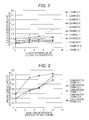
- the specific surface area of 2 g of the hydrogen storage alloy was measured by a BET method using a specific surface area measurement apparatus. The results of measurement are shown in Table 1 and graphs of Figs. 1 and 2 .
- a nickel-metal hydride battery of the present embodiment has a constitution described above, it can provide a nickel-metal hydride storage battery having a long life in an electrolyte solution containing a large amount of NaOH.
Landscapes
- Chemical & Material Sciences (AREA)
- Chemical Kinetics & Catalysis (AREA)
- Electrochemistry (AREA)
- General Chemical & Material Sciences (AREA)
- Engineering & Computer Science (AREA)
- Materials Engineering (AREA)
- Mechanical Engineering (AREA)
- Metallurgy (AREA)
- Organic Chemistry (AREA)
- Battery Electrode And Active Subsutance (AREA)
- Secondary Cells (AREA)
Description
- The present invention relates to a nickel-metal hydride storage battery.
- Nickel-metal hydride storage (rechargeable) batteries are widely used as power sources of microelectronic equipment such as digital cameras and laptops because of their high energy density, and used as alternative power sources to primary batteries such as alkaline manganese batteries because the nickel-metal hydride storage batteries are equal in the operating voltage to the primary batteries and are compatible with the primary batteries. Therefore, demands for the nickel-metal hydride storage battery are steadily expanding.
- Such a nickel-metal hydride storage battery uses a hydrogen storage alloy as a negative active material. An AB5-type rare earth-Ni-based alloy having a CaCu5-type crystal structure has been put to practical use as a hydrogen storage alloy. MmNi5 is known as a typical example thereof.
- However, the battery using the MmNi5-based alloy has a problem that the preservation property is not sufficient. The preservation property can be improved by using an electrolyte solution containing a large amount of NaOH. However, since the electrolyte solution containing a large amount of NaOH tends to corrode the hydrogen storage alloy compared with a commonly used electrolyte solution containing KOH as a main ingredient, there is a problem that the battery life is shortened (
JP-A-9-139230 - It is an object of the present invention to provide a nickel-metal hydride storage battery having a long life in an electrolyte solution containing a large amount of NaOH.
- The present inventor made earnest investigations, and consequently found that a hydrogen storage alloy having Y (yttrium) hardly causes corrosion even if an electrolyte solution containing a large amount of NaOH is used, and this finding has now led to completion of the present invention.
-
-
Fig. 1 is a graph showing a relationship between the NaOH concentration of an electrolyte solution and the specific surface area of hydrogen storage alloys (examples); and -
Fig. 2 is a graph showing a relationship between the NaOH concentration of an electrolyte solution and the specific surface area of hydrogen storage alloys (comparative examples). - Hereinafter, embodiments of a nickel-metal hydride storage (rechargeable) battery according to the present invention will be described.
- The nickel-metal hydride storage battery according to a first aspect of the present invention includes, for example, a negative electrode containing a hydrogen storage alloy as a negative active material, a positive electrode (nickel electrode) containing a positive active material containing nickel hydroxide as a main ingredient, a separator, and an electrolyte solution.
- In the first aspect of the present invention, the hydrogen storage alloy has a CaCu5-type crystal structure and contains at least a Ni element and a rare earth element, which is partly substituted with an Y element, and the electrolyte solution contains NaOH in an amount of 2.0 M or more. The corrosion of the hydrogen storage alloy in an electrolyte solution containing a large amount of NaOH can be suppressed since the hydrogen storage alloy contains Y. The reason for this is probably that a protective film of yttrium hydroxide formed on the surface of the alloy by the reaction of Y in the alloy with an electrolyte solution suppresses corrosion of the alloy due to NaOH.
- In a second aspect of the present invention, the hydrogen storage alloy includes a Ce element.
- In the third aspect of the present invention, the content of elements other than the rare earth element in the hydrogen storage alloy is 5.2 times or more than that of the rare earth element in terms of the number of atoms.
- In the fourth aspect of the present invention, the electrolyte solution includes NaOH in an amount of 6.0 M or more and 8.0 M or less.
- In the fifth aspect of the present invention, the hydrogen storage alloy contains at least one metal element selected from a group consisting of a Co element, a Mn element, and an Al element.
- In the sixth aspect of the present invention, the hydrogen storage alloy contains a Co element and the content of the Co element is 0.4 times or less than that of the rare earth element in terms of the number of atoms.
- The hydrogen storage alloy preferably contains a Ce element. The corrosion of the hydrogen storage alloy in an electrolyte solution containing a large amount of NaOH can be remarkably suppressed by such a configuration. The reason for this is probably that a protective film of a composite of yttrium hydroxide and cerium hydroxide is formed on the surface of the alloy by the reaction of Y and Ce in the alloy with an electrolyte solution and the protective film suppresses corrosion of the alloy due to NaOH.
- The content of elements other than the rare-earth elements in the hydrogen storage alloy is preferably 5.1 times or more, and more preferably 5.2 times or more than that of the rare-earth elements in terms of the number of atoms. When the content is less than 5.1 times, durability of the alloy is lowered, and when the content is 5.2 times or more, sufficient alloy durability is achieved.
- The upper limit of the content of elements other than the rare-earth elements in the hydrogen storage alloy is not particularly limited, but it is preferably 5.4 times or less than that of the rare-earth elements in terms of the number of atoms. The upper limit of the content is more preferably 5.3 times or less. When the upper limit of the content is more than 5.4 times, the CaCu5-type crystal structure may not be formed, and the hydrogen storage capability may be lost. Further, with respect to the contents of the respective elements in the alloy when the total of the contents (in terms of the number of atoms) of the rare-earth elements is taken as 1, preferably, the content of a La element is 0.5 to 0.9, the content of a Y element is 0.05 to 0.4, and the content of a Ce element is 0.05 to 0.3. When the content of the Y element is 0.05 or more, the effect of improving corrosion resistance is achieved, and when the content of the Y element is more than 0.4, yttrium is segregated and alloy durability is deteriorated. When the content of the Ce element is 0.05 or more, the effect of improving corrosion resistance is achieved, and when the content of the Ce element is more than 0.3, alloy durability is deteriorated. The content of the Ni element is preferably 4.35 to 4.55 times that of the rare-earth elements in terms of the number of atoms, and the content of elements other than the rare-earth elements and the Ni element in the hydrogen storage alloy is preferably 0.85 to 0.95 times that of the rare-earth elements in terms of the number of atoms. When the content of elements other than the rare-earth elements and the Ni element is more than 0.95 times, preservation property is lowered due to fine short-circuiting, and when the content is less than 0.85 times, durability of the alloy is lowered.
- Examples of the elements other than the rare-earth elements and the Ni element in the hydrogen storage alloy include Co, Mn, Al, Fe, Cu, Cr, and Zn. Among these elements, Co, Mn and Al are preferable, and Co is particularly suitably used. A Ni-Co alloy layer having high corrosion resistance is formed on the alloy surface due to Co contained in the alloy composition. Since the Ni-Co alloy layer has higher corrosion resistance than a low-density layer of Ni alone, which is formed on an alloy not containing Co, the alloy containing Co has higher corrosion resistance than the alloy not containing Co in an electrolyte solution. The content of the Co element is preferably 0.4 times or less that of the rare-earth elements in terms of the number of atoms.
- In the hydrogen storage alloy, Co is more preferably used in combination with Mn and Al. An example of the preferred hydrogen storage alloy in the case of combined use of Co, Mn and Al is a hydrogen storage alloy represented by the general formula La(1-x-y)YxCeyNiaCocMnb1Alb2, wherein c, b1 and b2 preferably satisfy the relations of 0.01 ≤ c ≤ 0.4, 0.1 ≤ b1 ≤ 0.4 and 0.35 ≤ b2 ≤ 0.45.
- In addition, the hydrogen storage alloy may contain an element not defined by the general formula as inevitable impurities in addition to the alloy represented by the general formula.
- A method of manufacturing the hydrogen storage alloy is not particularly limited, and examples thereof include a melt spinning method, an arc melting method, a casting method, and a gas atomizing method. The hydrogen storage alloy can be manufactured by selecting an appropriate method from these.
- The hydrogen storage alloy is compounded in a negative electrode in the form of a hydrogen storage alloy powder, for example. The average particle size of the hydrogen storage alloy powder is preferably 20 to 100 µm, and more preferably 40 to 70 µm. When the average particle size is less than 20 µm, activation of the alloy is insufficient, and on the other hand, when the average particle diameter is more than 100 µm, the productivity may be lowered. The hydrogen storage alloy powder is obtained by crushing the hydrogen storage alloy with a machine in the presence of an inert gas, for example.
- The negative electrode may contain a conductive agent, a binder (including a thickener) and the like in addition to the hydrogen storage alloy.
- Examples of the conductive agent include carbon-based conductive agents such as natural graphite (scaly graphite, flake graphite, amorphous graphite, etc.), synthetic graphite, carbon black, acetylene black, Ketjen black, carbon whisker, carbon fiber, and vapor-grown carbon; and metallic conductive agents made of a powder or fiber of metals such as nickel, cobalt, and copper. These conductive agents may be used alone or in combination of two or more species. The negative electrode may also contain a rare-earth oxide such as yttrium oxide as an anticorrosive.
- The compounded amount of the conductive agent is preferably 0.1 to 10 parts by mass, and more preferably 0.2 to 5 parts by mass with respect to 100 parts by mass of the hydrogen storage alloy. When the compounded amount of the conductive agent is less than 0.1 part by mass, it is hard to obtain sufficient conductivity. On the other hand, when the compounded amount of the conductive agent is more than 10 parts by mass, the effect of improving the discharge capacity may be insufficient.
- Examples of the binder include polytetrafluoroethylene (PTFE), polyolefin-based resins such as polyethylene and polypropylene, ethylene-propylene-diene terpolymer (EPDM), sulfonated EPDM, styrene-butadiene rubber (SBR), fluorine-contained rubber, polyvinyl alcohol, methylcellulose, carboxymethylcellulose, and xanthan gum. These binders may be used alone or in combination of two or more species.
- The compounded amount of the binder is preferably 0.1 to 1.0 part by mass, and more preferably 0.5 to 1.0 part by mass with respect to 100 parts by mass of the hydrogen storage alloy powder. When the compounded amount of the binder is less than 0.1 part by mass, an adequate thickening property is hardly achieved. On the other hand, when the compounded amount of the binder is more than 1.0 part by mass, electrode performance may be insufficient.
- Examples of the positive electrode include electrodes in which a nickel hydroxide composite oxide, formed by mixing nickel hydroxide as a main ingredient with zinc hydroxide or cobalt hydroxide, is compounded as a positive active material. As the nickel hydroxide composite oxide, a composite oxide uniformly dispersed by a coprecipitation method is suitably used.
- The positive electrode preferably contains an additive for improving electrode performance in addition to the nickel hydroxide composite oxide. Examples of the additive include conduction modifiers such as cobalt hydroxide and cobalt oxide, and the nickel hydroxide composite oxide coated with cobalt hydroxide. Alternatively, the nickel hydroxide composite oxide, a part of which is oxidized by oxygen or oxygen-containing gas, K2S2O8, hypochlorous acid, or the like, may also be used.
- As the additive, compounds containing rare-earth elements such as Y and Yb, or compounds that increase the overvoltage of oxygen generation such as Ca compounds can also be used. The rare-earth elements such as Y and Yb can also be expected to be effective for suppressing the corrosion of the negative active material since a part of the rare-earth elements is dissolved in an electrolyte solution and deposited on the surface of the negative electrode.
- The positive electrode may further contain the conductive agent and the binder described above, similarly to the negative electrode.
- These positive electrode and negative electrode can each be manufactured by the following procedures. The conductive agent and the binder described above are added to the active material as required. The resulting mixture is kneaded with water or an organic solvent such as alcohol or toluene to obtain a paste. The paste is applied to a conductive support and dried, and then subjected to roll forming, for example.
- Examples of the conductive support include steel sheets and plated steel sheets obtained by plating a steel sheet with a metal material such as nickel. Examples of shape of the conductive support include three-dimensional substrates such as a foam, a shaped body of fibers, and a substrate subjected to pebbling; and two-dimensional substrates such as a punched plate. Among these conductive supports, as the support for the positive electrode, a foam which is made of nickel having excellent corrosion resistance to alkalis and oxidation resistance and has a porous structure, a structure having excellent current collecting performance, is preferable. On the other hand, as the conductive support for the negative electrode, a perforated steel sheet, that is formed by nickel-plating an iron foil which is inexpensive and excellent in conductivity, is preferable.
- The thickness of the conductive support is preferably 30 to 100 µm, and more preferably 40 to 70 µm. When the thickness of the conductive support is less than 30 µm, the productivity may be lowered. On the other hand, when the thickness of the conductive support is more than 100 µm, the discharge capacity may be insufficient.
- When the conductive support is a perforated steel sheet, the inner diameter of the hole is preferably 0.8 to 2 µm, and more preferably 1 to 1.5 µm. When the inner diameter of the hole is less than 0.8 µm, the productivity may be lowered. On the other hand, when the inner diameter is more than 2 µm, the performance of retaining the hydrogen storage alloy may be insufficient.
- Examples of a method of applying a paste for electrodes to the conductive support include a roller coating method using an applicator roll, a screen coating method, a blade coating method, a spin coating method, and a bar coating method.
- Examples of the separator include porous membranes or non-woven cloths made of a polyolefin-based resin such as polyethylene or polypropylene, acrylic, polyamide or the like.
- The weight per unit area of the separator is preferably 40 to 100 g/m2. When the weight per unit area is less than 40 g/m2, a short circuit or deterioration in self discharge performance may occur. On the other hand, when the weight per unit area is more than 100 g/m2, since the proportion of the separator per unit volume is increased, the battery capacity tends to decrease. Further, the air permeability of the separator is preferably 1 to 50 cm/sec. When the air permeability is less than 1 cm/sec, the battery internal pressure may become too high. On the other hand, when the air permeability is more than 50 cm/sec, a short circuit or deterioration in self discharge performance may occur. Moreover, the average fiber diameter of the separator is preferably 1 to 20 µm. When the average fiber diameter is less than 1 µm, the strength of the separator may be lowered, resulting in an increase in the percent defective in a battery-assembling step. On the other hand, when the average fiber diameter is more than 20 µm, a short circuit or deterioration in self discharge performance may occur.
- The fiber surface of the separator is preferably subjected to hydrophilization treatment. Examples of the hydrophilization treatment include sulfonation treatment, corona treatment, fluorine gas treatment, and plasma treatment. Particularly, a separator with fiber surfaces subjected to sulfonation treatment has a high effect of suppressing self discharge and is preferred since it has a high ability of adsorbing impurities such as N03 -, NO2 - and NH3 - which cause a shuttle phenomenon, and an element eluted from the negative electrode.
- The electrolyte solution used in the present embodiment contains NaOH (sodium hydroxide) in an amount of 2.0 M or more, and preferably in an amount of 6.0 M or more. It is possible to improve the preservation property of a battery and prevent corrosion of the hydrogen storage alloy simultaneously by applying the electrolyte solution to the hydrogen storage alloy, and consequently the battery life can be lengthened.
- An alkaline electrolyte contained in the electrolyte solution may be NaOH alone, but KOH (potassium hydroxide) or LiOH (lithium hydroxide) may be used in combination with NaOH.
- With respect to the concentration of the electrolyte solution, the total of ion concentrations is preferably 8.0 M or less, and more preferably 5.0 to 8.0 M. Further, it is preferred that NaOH is used in combination with KOH so as to give such an ion concentration.
- Various additives may be added to the electrolyte solution in order to improve the overvoltage of oxygen generation at the positive electrode, corrosion resistance at the negative electrode, and self-discharge resistance. Examples of such additives include oxides and hydroxides of yttrium, ytterbium, erbium, calcium, and zinc. These additives may be used alone or in combination of two or more species.
- When the nickel-metal hydride storage battery of the present embodiment is an open type nickel-metal hydride storage battery, the battery can be manufactured, for example, by a method of sandwiching a negative electrode between positive electrodes with a separator interposed between the negative electrode and each of the positive electrodes, pouring an electrolyte solution in a state where the electrodes are fixed so that a predetermined pressure is applied to these electrodes, and assembling an open type cell.
- On the other hand, when the nickel-metal hydride storage battery of the present embodiment is a sealed nickel-metal hydride storage battery, the battery can be manufactured by a method of pouring an electrolyte solution before or after stacking a positive electrode, a separator and a negative electrode, and sealing the battery with a casing material. Further, in the sealed nickel-metal hydride storage battery prepared by winding a power generating element formed by stacking the positive electrode and the negative electrode with the separator interposed therebetween, it is preferred that the electrolyte solution is poured into the battery case before or after winding the power generating element. The method of pouring the electrolyte solution is not particularly limited, and the electrolyte solution may be poured at a normal pressure. The electrolyte solution may be poured by using a vacuum impregnation method, a pressure impregnation method or a centrifugal impregnation method. Examples of the battery case and the casing material of the sealed nickel-metal hydride storage battery include materials made of iron, iron plated with a metal material such as nickel, stainless steel and a polyolefin-based resin.
- The type of the sealed nickel-metal hydride storage battery is not particularly limited, and examples thereof include batteries including a positive electrode, a negative electrode and a monolayer or multilayer separator, such as coin batteries, button batteries, prismatic batteries, and flat type batteries; and cylindrical batteries including a positive electrode, a negative electrode and a separator which are formed into a roll.
- Hereinafter, the present embodiment will be described in more detail by way of examples, but the present invention is not limited to these examples.
- In 60 mL of an electrolyte solution obtained by dissolving NaOH and KOH in such a way that the total concentration thereof was 8 M, 5 g of a hydrogen storage alloy in each of examples and comparative examples, the composition of which is shown in Table 1 described below, was immersed, and was left standing in a thermostat bath kept at 80°C for 72 hours. The hydrogen storage alloys in comparative examples do not contain Y. Each of the alloys used was an alloy in which a large part of the crystal structure was a CaCu5-type crystal structure, and which has a B/A ratio of 5.1 to 5.4. The B/A ratio is a ratio of elements other than the rare-earth elements to the rare-earth elements in the hydrogen storage alloy.
- After being left standing in the thermostat bath, each hydrogen storage alloy was isolated, washed and dried. The specific surface area of 2 g of the hydrogen storage alloy was measured by a BET method using a specific surface area measurement apparatus. The results of measurement are shown in Table 1 and graphs of
Figs. 1 and 2 .
- Since the specific surface area shows a positive correlation with the corrosion, a larger specific surface area shows that the corrosion has progressed. Accordingly, it is found from the graph of
Fig. 1 that a progress in corrosion due to NaOH was suppressed in examples. Particularly, in Examples 1 to 9 in which the hydrogen storage alloy contained both of Y and Ce, it is found that the corrosion did not progress in any hydrogen storage alloy. On the other hand, it is found that corrosion remarkably progressed with increases in the ratio of NaOH in any hydrogen storage alloy in comparative examples. - Since a nickel-metal hydride battery of the present embodiment has a constitution described above, it can provide a nickel-metal hydride storage battery having a long life in an electrolyte solution containing a large amount of NaOH.
Claims (6)
- A nickel-metal hydride storage battery comprising:a negative electrode containing a hydrogen storage alloy; andan electrolyte solution,wherein the hydrogen storage alloy has a CaCus-type crystal structure and contains at least a Ni element and a rare earth element,wherein the rare earth element is partly substituted with an Y element, andwherein the electrolyte solution contains NaOH in an amount of 2.0 M or more.
- The nickel-metal hydride storage battery according to claim1, wherein the hydrogen storage alloy contains a Ce element.
- The nickel-metal hydride storage battery according to claim1 or 2, wherein the content of elements other than the rare earth element in the hydrogen storage alloy is 5.2 times or more than that of the rare earth element in terms of the number of atoms.
- The nickel-metal hydride storage battery according to any one of claims 1 to 3, wherein the electrolyte solution contains NaOH in an amount of 6.0 M or more and 8.0 M or less.
- The nickel-metal hydride storage battery according to any one of claims 1 to 4, wherein the hydrogen storage alloy contains at least one metal element selected from a group consisting of a Co element, a Mn element and an Al element.
- The nickel-metal hydride storage battery according to any one of claims 1 to 5, wherein the hydrogen storage alloy contains a Co element and the content of the Co element is 0.4 times or less than that of the rare earth element in terms of the number of atoms.
Applications Claiming Priority (1)
| Application Number | Priority Date | Filing Date | Title |
|---|---|---|---|
| JP2012214202A JP5716969B2 (en) | 2012-09-27 | 2012-09-27 | Nickel metal hydride storage battery |
Publications (2)
| Publication Number | Publication Date |
|---|---|
| EP2713426A1 true EP2713426A1 (en) | 2014-04-02 |
| EP2713426B1 EP2713426B1 (en) | 2018-02-14 |
Family
ID=49230655
Family Applications (1)
| Application Number | Title | Priority Date | Filing Date |
|---|---|---|---|
| EP13186194.0A Active EP2713426B1 (en) | 2012-09-27 | 2013-09-26 | Nickel-metal hydride storage battery |
Country Status (4)
| Country | Link |
|---|---|
| US (1) | US9490477B2 (en) |
| EP (1) | EP2713426B1 (en) |
| JP (1) | JP5716969B2 (en) |
| CN (1) | CN103700895B (en) |
Cited By (1)
| Publication number | Priority date | Publication date | Assignee | Title |
|---|---|---|---|---|
| EP3163668A4 (en) * | 2014-06-27 | 2017-11-22 | FDK Corporation | Nickel hydrogen secondary battery |
Families Citing this family (3)
| Publication number | Priority date | Publication date | Assignee | Title |
|---|---|---|---|---|
| US10566614B2 (en) | 2014-08-28 | 2020-02-18 | Baotou Research Institute of Rare Earths | Rare earth based hydrogen storage alloy and application thereof |
| CN104513925B (en) * | 2014-08-28 | 2017-05-03 | 包头稀土研究院 | Yttrium-nickel rare earth family hydrogen storage alloy, and secondary battery containing hydrogen storage alloy |
| CN111082037B (en) * | 2019-12-31 | 2021-09-03 | 有研工程技术研究院有限公司 | Nickel-hydrogen secondary battery |
Citations (2)
| Publication number | Priority date | Publication date | Assignee | Title |
|---|---|---|---|---|
| JPH09139230A (en) | 1995-09-14 | 1997-05-27 | Toshiba Battery Co Ltd | Alkaline secondary battery |
| EP2628812A1 (en) * | 2012-02-20 | 2013-08-21 | GS Yuasa International Ltd. | Hydrogen storage alloy, electrode, nickel-metal hydride rechargeable battery and method for producing hydrogen storage alloy |
Family Cites Families (18)
| Publication number | Priority date | Publication date | Assignee | Title |
|---|---|---|---|---|
| US5512385A (en) * | 1994-02-28 | 1996-04-30 | Matsushita Electric Industrial Co., Ltd. | Hydrogen storage alloy and nickel-metal hydride storage battery using the same |
| JP2965475B2 (en) * | 1994-02-28 | 1999-10-18 | 松下電器産業株式会社 | Hydrogen storage alloy |
| JPH09209065A (en) | 1994-11-07 | 1997-08-12 | Santoku Kinzoku Kogyo Kk | Age precipitation type rare earth metal-nickel alloy, its production, and nickel-hydrogen secondary battery negative pole |
| KR100216305B1 (en) | 1995-04-03 | 1999-08-16 | 이노우에 유스케 | Rare earth metal-nickel hydrogen storage alloy, preparation method thereof and anode for nickel hydride secondary battery |
| JP3737163B2 (en) | 1995-07-10 | 2006-01-18 | 株式会社三徳 | Rare earth metal-nickel hydrogen storage alloy and negative electrode for nickel metal hydride secondary battery |
| EP0783040B1 (en) | 1995-07-10 | 2001-11-07 | Santoku Metal Industry Co., Ltd. | Rare earth metal-nickel hydrogen storage alloy, process for producing the same, and anode for nickel-hydrogen rechargeable battery |
| JP3748122B2 (en) | 1996-02-06 | 2006-02-22 | 東芝電池株式会社 | Method for producing alkaline storage battery |
| US5965295A (en) | 1996-06-14 | 1999-10-12 | Toshiba Battery Co., Ltd. | Alkaline secondary battery, paste type positive electrode for alkaline secondary battery, method for manufacturing alkaline secondary battery |
| EP0955386B1 (en) * | 1996-09-06 | 2004-01-21 | Santoku Corporation | Rare earth metal-nickel-hydrogen storage alloy, a method for producing the same, and anode for nickel-hydrogen rechargeable battery |
| JP2001143745A (en) | 1999-11-12 | 2001-05-25 | Matsushita Electric Ind Co Ltd | Nickel-metal hydride battery |
| JP3673693B2 (en) | 2000-03-29 | 2005-07-20 | 日本重化学工業株式会社 | Hydrogen storage alloy |
| JP5437544B2 (en) | 2001-06-11 | 2014-03-12 | 株式会社三徳 | Manufacturing method of negative electrode for secondary battery |
| JP3861788B2 (en) | 2002-09-30 | 2006-12-20 | 株式会社ユアサ開発 | Hydrogen storage alloy powder, hydrogen storage alloy electrode and nickel metal hydride storage battery using the same. |
| JP2007149646A (en) | 2005-10-28 | 2007-06-14 | Sanyo Electric Co Ltd | Nickel metal hydride storage battery |
| WO2008018494A1 (en) * | 2006-08-09 | 2008-02-14 | Gs Yuasa Corporation | Hydrogen storage alloy, hydrogen storage alloy electrode, secondary battery, and method for producing hydrogen storage alloy |
| JP5179777B2 (en) | 2007-03-30 | 2013-04-10 | 株式会社三徳 | Hydrogen storage alloy, negative electrode for nickel metal hydride secondary battery, nickel metal hydride secondary battery |
| JP5481803B2 (en) | 2008-05-02 | 2014-04-23 | 株式会社Gsユアサ | Nickel metal hydride storage battery |
| JP2011127185A (en) | 2009-12-18 | 2011-06-30 | Santoku Corp | Hydrogen storage alloy, method for producing the same, negative electrode for nickel hydrogen secondary battery and nickel hydrogen secondary battery |
-
2012
- 2012-09-27 JP JP2012214202A patent/JP5716969B2/en active Active
-
2013
- 2013-09-25 CN CN201310447163.XA patent/CN103700895B/en active Active
- 2013-09-25 US US14/036,228 patent/US9490477B2/en active Active
- 2013-09-26 EP EP13186194.0A patent/EP2713426B1/en active Active
Patent Citations (2)
| Publication number | Priority date | Publication date | Assignee | Title |
|---|---|---|---|---|
| JPH09139230A (en) | 1995-09-14 | 1997-05-27 | Toshiba Battery Co Ltd | Alkaline secondary battery |
| EP2628812A1 (en) * | 2012-02-20 | 2013-08-21 | GS Yuasa International Ltd. | Hydrogen storage alloy, electrode, nickel-metal hydride rechargeable battery and method for producing hydrogen storage alloy |
Non-Patent Citations (5)
| Title |
|---|
| BADDOUR-HADJEAN R ET AL: "An electrochemical study of new La1-xCexY2Ni9 (0=<x=<1) hydrogen storage alloys", ELECTROCHIMICA ACTA, ELSEVIER SCIENCE PUBLISHERS, BARKING, GB, vol. 46, no. 15, 30 April 2001 (2001-04-30), pages 2385 - 2393, XP004234032, ISSN: 0013-4686, DOI: 10.1016/S0013-4686(01)00440-6 * |
| O. ARNAUD ET AL: "Effect of Yttria Content on Corrosion of AB[sub 5]-Type Alloys for Nickel-Metal Hydride Batteries", JOURNAL OF THE ELECTROCHEMICAL SOCIETY, vol. 152, no. 3, 1 January 2005 (2005-01-01), pages A611, XP055092674, ISSN: 0013-4651, DOI: 10.1149/1.1857771 * |
| W LI ET AL: "Effects of Y Substitution for La on the Microstructure and Electrochemical Properties of LaNi3.55Mn0.4Al0.3Co0.75 Hydrogen Storage Alloys", MATERIALS TRANSACTIONS, 1 January 2008 (2008-01-01), pages 2229 - 2232, XP055092538, Retrieved from the Internet <URL:http://japanlinkcenter.org/JST.JSTAGE/matertrans/MA200809?from=SUMMON> DOI: 10.2320/matertrans.MA200809 * |
| XIANYUN PENG ET AL: "Microstructures and Electrochemical Hydrogen Storage Characteristics of La 0.65-x Ce 0.25- x Pr 0.03 Nd 0.07 Y 2x Ni 3.65 Co 0.75 Mn 0.3 Al 0.3 (x = 0-0.04) Alloys", INT. J. ELECTROCHEM. SCI. INTERNATIONAL JOURNAL, vol. 8, 1 January 2013 (2013-01-01), pages 2262 - 2271, XP055092700 * |
| YULEI DU ET AL: "Structural and electrochemical properties of annealed La1-xYxNi3.55Mno.4Alo.3Coo.75 hydrogen storage alloys", JOURNAL OF ENVIRONMENTAL SCIENCES, vol. 23, 1 June 2011 (2011-06-01), pages S59 - S62, XP055092668, ISSN: 1001-0742, DOI: 10.1016/S1001-0742(11)61078-4 * |
Cited By (2)
| Publication number | Priority date | Publication date | Assignee | Title |
|---|---|---|---|---|
| EP3163668A4 (en) * | 2014-06-27 | 2017-11-22 | FDK Corporation | Nickel hydrogen secondary battery |
| US10693194B2 (en) | 2014-06-27 | 2020-06-23 | Fdk Corporation | Nickel hydrogen secondary battery |
Also Published As
| Publication number | Publication date |
|---|---|
| CN103700895A (en) | 2014-04-02 |
| CN103700895B (en) | 2018-02-06 |
| EP2713426B1 (en) | 2018-02-14 |
| JP5716969B2 (en) | 2015-05-13 |
| JP2014067683A (en) | 2014-04-17 |
| US20140087253A1 (en) | 2014-03-27 |
| US9490477B2 (en) | 2016-11-08 |
Similar Documents
| Publication | Publication Date | Title |
|---|---|---|
| JP5495887B2 (en) | Negative electrode for non-aqueous electrolyte battery and non-aqueous electrolyte battery | |
| CN104380503B (en) | Negative electrode for lithium rechargeable battery, lithium rechargeable battery, and method for producing negative electrode for lithium rechargeable battery | |
| CN103259003B (en) | The manufacture method of hydrogen-storage alloy, electrode, nickel-hydrogen accumulator and hydrogen-storage alloy | |
| CN102110839A (en) | a battery | |
| JPWO2018021361A1 (en) | Magnesium-lithium alloy and magnesium air battery | |
| JP2009206004A (en) | Anode for alkaline storage battery and alkaline storage battery | |
| US20160218366A1 (en) | DISORDERED ANODES FOR Ni-METAL RECHARGEABLE BATTERY | |
| JP2020155266A (en) | Zinc battery electrolyte and zinc battery | |
| US20060166099A1 (en) | Closed nickel-hydrogen storage battery and its production method | |
| JP6094902B2 (en) | Positive electrode for alkaline storage battery and alkaline storage battery using the same | |
| JP2008071759A (en) | Anode composition comprising negative electrode composition and composition of alkaline electrolyte battery, alkaline electrolyte battery comprising this anode | |
| CN105990582A (en) | Battery | |
| JP2012227106A (en) | Nickel metal hydride storage battery | |
| EP2713426B1 (en) | Nickel-metal hydride storage battery | |
| JP2012188728A (en) | Composite hydrogen-storage alloy and nickel-metal hydride storage battery | |
| CN106463786A (en) | Nickel hydrogen secondary battery | |
| JP5217826B2 (en) | Nickel metal hydride storage battery | |
| US10323301B2 (en) | Hydrogen storing alloy, electrode, and nickel-hydrogen storage battery | |
| JP6394955B2 (en) | Hydrogen storage alloy, electrode and nickel metal hydride storage battery | |
| JP6422017B2 (en) | Hydrogen storage alloy, electrode and nickel metal hydride storage battery | |
| CN109585942B (en) | Method and composition for improving high temperature performance of NIMH batteries | |
| JP5769028B2 (en) | Nickel metal hydride storage battery | |
| JP6406796B2 (en) | Hydrogen storage alloy, electrode, nickel metal hydride storage battery, and method for producing hydrogen storage alloy | |
| CN110380140B (en) | Negative electrode for alkaline secondary battery and alkaline secondary battery | |
| JP4930674B2 (en) | Sealed alkaline storage battery and its assembled battery |
Legal Events
| Date | Code | Title | Description |
|---|---|---|---|
| PUAI | Public reference made under article 153(3) epc to a published international application that has entered the european phase |
Free format text: ORIGINAL CODE: 0009012 |
|
| AK | Designated contracting states |
Kind code of ref document: A1 Designated state(s): AL AT BE BG CH CY CZ DE DK EE ES FI FR GB GR HR HU IE IS IT LI LT LU LV MC MK MT NL NO PL PT RO RS SE SI SK SM TR |
|
| AX | Request for extension of the european patent |
Extension state: BA ME |
|
| 17P | Request for examination filed |
Effective date: 20140930 |
|
| RBV | Designated contracting states (corrected) |
Designated state(s): AL AT BE BG CH CY CZ DE DK EE ES FI FR GB GR HR HU IE IS IT LI LT LU LV MC MK MT NL NO PL PT RO RS SE SI SK SM TR |
|
| 17Q | First examination report despatched |
Effective date: 20150729 |
|
| GRAP | Despatch of communication of intention to grant a patent |
Free format text: ORIGINAL CODE: EPIDOSNIGR1 |
|
| STAA | Information on the status of an ep patent application or granted ep patent |
Free format text: STATUS: GRANT OF PATENT IS INTENDED |
|
| RIC1 | Information provided on ipc code assigned before grant |
Ipc: C22C 19/00 20060101ALI20170828BHEP Ipc: H01M 10/34 20060101ALN20170828BHEP Ipc: H01M 4/38 20060101AFI20170828BHEP |
|
| RIC1 | Information provided on ipc code assigned before grant |
Ipc: H01M 10/34 20060101ALN20170907BHEP Ipc: C22C 19/00 20060101ALI20170907BHEP Ipc: H01M 4/38 20060101AFI20170907BHEP |
|
| INTG | Intention to grant announced |
Effective date: 20170920 |
|
| RIN1 | Information on inventor provided before grant (corrected) |
Inventor name: KAKEYA, TADASHI Inventor name: KODAMA, MITSUHIRO Inventor name: OKUDA, DAISUKE Inventor name: KANEMOTO, MANABU |
|
| GRAS | Grant fee paid |
Free format text: ORIGINAL CODE: EPIDOSNIGR3 |
|
| GRAA | (expected) grant |
Free format text: ORIGINAL CODE: 0009210 |
|
| STAA | Information on the status of an ep patent application or granted ep patent |
Free format text: STATUS: THE PATENT HAS BEEN GRANTED |
|
| AK | Designated contracting states |
Kind code of ref document: B1 Designated state(s): AL AT BE BG CH CY CZ DE DK EE ES FI FR GB GR HR HU IE IS IT LI LT LU LV MC MK MT NL NO PL PT RO RS SE SI SK SM TR |
|
| REG | Reference to a national code |
Ref country code: GB Ref legal event code: FG4D |
|
| REG | Reference to a national code |
Ref country code: CH Ref legal event code: EP |
|
| REG | Reference to a national code |
Ref country code: IE Ref legal event code: FG4D |
|
| REG | Reference to a national code |
Ref country code: DE Ref legal event code: R096 Ref document number: 602013033038 Country of ref document: DE Ref country code: AT Ref legal event code: REF Ref document number: 970411 Country of ref document: AT Kind code of ref document: T Effective date: 20180315 |
|
| REG | Reference to a national code |
Ref country code: NL Ref legal event code: MP Effective date: 20180214 |
|
| REG | Reference to a national code |
Ref country code: AT Ref legal event code: MK05 Ref document number: 970411 Country of ref document: AT Kind code of ref document: T Effective date: 20180214 |
|
| PG25 | Lapsed in a contracting state [announced via postgrant information from national office to epo] |
Ref country code: ES Free format text: LAPSE BECAUSE OF FAILURE TO SUBMIT A TRANSLATION OF THE DESCRIPTION OR TO PAY THE FEE WITHIN THE PRESCRIBED TIME-LIMIT Effective date: 20180214 Ref country code: NL Free format text: LAPSE BECAUSE OF FAILURE TO SUBMIT A TRANSLATION OF THE DESCRIPTION OR TO PAY THE FEE WITHIN THE PRESCRIBED TIME-LIMIT Effective date: 20180214 Ref country code: CY Free format text: LAPSE BECAUSE OF FAILURE TO SUBMIT A TRANSLATION OF THE DESCRIPTION OR TO PAY THE FEE WITHIN THE PRESCRIBED TIME-LIMIT Effective date: 20180214 Ref country code: NO Free format text: LAPSE BECAUSE OF FAILURE TO SUBMIT A TRANSLATION OF THE DESCRIPTION OR TO PAY THE FEE WITHIN THE PRESCRIBED TIME-LIMIT Effective date: 20180514 Ref country code: FI Free format text: LAPSE BECAUSE OF FAILURE TO SUBMIT A TRANSLATION OF THE DESCRIPTION OR TO PAY THE FEE WITHIN THE PRESCRIBED TIME-LIMIT Effective date: 20180214 Ref country code: LT Free format text: LAPSE BECAUSE OF FAILURE TO SUBMIT A TRANSLATION OF THE DESCRIPTION OR TO PAY THE FEE WITHIN THE PRESCRIBED TIME-LIMIT Effective date: 20180214 Ref country code: HR Free format text: LAPSE BECAUSE OF FAILURE TO SUBMIT A TRANSLATION OF THE DESCRIPTION OR TO PAY THE FEE WITHIN THE PRESCRIBED TIME-LIMIT Effective date: 20180214 |
|
| PG25 | Lapsed in a contracting state [announced via postgrant information from national office to epo] |
Ref country code: LV Free format text: LAPSE BECAUSE OF FAILURE TO SUBMIT A TRANSLATION OF THE DESCRIPTION OR TO PAY THE FEE WITHIN THE PRESCRIBED TIME-LIMIT Effective date: 20180214 Ref country code: SE Free format text: LAPSE BECAUSE OF FAILURE TO SUBMIT A TRANSLATION OF THE DESCRIPTION OR TO PAY THE FEE WITHIN THE PRESCRIBED TIME-LIMIT Effective date: 20180214 Ref country code: RS Free format text: LAPSE BECAUSE OF FAILURE TO SUBMIT A TRANSLATION OF THE DESCRIPTION OR TO PAY THE FEE WITHIN THE PRESCRIBED TIME-LIMIT Effective date: 20180214 Ref country code: AT Free format text: LAPSE BECAUSE OF FAILURE TO SUBMIT A TRANSLATION OF THE DESCRIPTION OR TO PAY THE FEE WITHIN THE PRESCRIBED TIME-LIMIT Effective date: 20180214 Ref country code: GR Free format text: LAPSE BECAUSE OF FAILURE TO SUBMIT A TRANSLATION OF THE DESCRIPTION OR TO PAY THE FEE WITHIN THE PRESCRIBED TIME-LIMIT Effective date: 20180515 Ref country code: BG Free format text: LAPSE BECAUSE OF FAILURE TO SUBMIT A TRANSLATION OF THE DESCRIPTION OR TO PAY THE FEE WITHIN THE PRESCRIBED TIME-LIMIT Effective date: 20180514 |
|
| PG25 | Lapsed in a contracting state [announced via postgrant information from national office to epo] |
Ref country code: IT Free format text: LAPSE BECAUSE OF FAILURE TO SUBMIT A TRANSLATION OF THE DESCRIPTION OR TO PAY THE FEE WITHIN THE PRESCRIBED TIME-LIMIT Effective date: 20180214 Ref country code: RO Free format text: LAPSE BECAUSE OF FAILURE TO SUBMIT A TRANSLATION OF THE DESCRIPTION OR TO PAY THE FEE WITHIN THE PRESCRIBED TIME-LIMIT Effective date: 20180214 Ref country code: EE Free format text: LAPSE BECAUSE OF FAILURE TO SUBMIT A TRANSLATION OF THE DESCRIPTION OR TO PAY THE FEE WITHIN THE PRESCRIBED TIME-LIMIT Effective date: 20180214 Ref country code: PL Free format text: LAPSE BECAUSE OF FAILURE TO SUBMIT A TRANSLATION OF THE DESCRIPTION OR TO PAY THE FEE WITHIN THE PRESCRIBED TIME-LIMIT Effective date: 20180214 Ref country code: AL Free format text: LAPSE BECAUSE OF FAILURE TO SUBMIT A TRANSLATION OF THE DESCRIPTION OR TO PAY THE FEE WITHIN THE PRESCRIBED TIME-LIMIT Effective date: 20180214 |
|
| REG | Reference to a national code |
Ref country code: DE Ref legal event code: R097 Ref document number: 602013033038 Country of ref document: DE |
|
| PG25 | Lapsed in a contracting state [announced via postgrant information from national office to epo] |
Ref country code: SM Free format text: LAPSE BECAUSE OF FAILURE TO SUBMIT A TRANSLATION OF THE DESCRIPTION OR TO PAY THE FEE WITHIN THE PRESCRIBED TIME-LIMIT Effective date: 20180214 Ref country code: SK Free format text: LAPSE BECAUSE OF FAILURE TO SUBMIT A TRANSLATION OF THE DESCRIPTION OR TO PAY THE FEE WITHIN THE PRESCRIBED TIME-LIMIT Effective date: 20180214 Ref country code: DK Free format text: LAPSE BECAUSE OF FAILURE TO SUBMIT A TRANSLATION OF THE DESCRIPTION OR TO PAY THE FEE WITHIN THE PRESCRIBED TIME-LIMIT Effective date: 20180214 Ref country code: CZ Free format text: LAPSE BECAUSE OF FAILURE TO SUBMIT A TRANSLATION OF THE DESCRIPTION OR TO PAY THE FEE WITHIN THE PRESCRIBED TIME-LIMIT Effective date: 20180214 |
|
| PLBE | No opposition filed within time limit |
Free format text: ORIGINAL CODE: 0009261 |
|
| STAA | Information on the status of an ep patent application or granted ep patent |
Free format text: STATUS: NO OPPOSITION FILED WITHIN TIME LIMIT |
|
| 26N | No opposition filed |
Effective date: 20181115 |
|
| PG25 | Lapsed in a contracting state [announced via postgrant information from national office to epo] |
Ref country code: SI Free format text: LAPSE BECAUSE OF FAILURE TO SUBMIT A TRANSLATION OF THE DESCRIPTION OR TO PAY THE FEE WITHIN THE PRESCRIBED TIME-LIMIT Effective date: 20180214 |
|
| PG25 | Lapsed in a contracting state [announced via postgrant information from national office to epo] |
Ref country code: MC Free format text: LAPSE BECAUSE OF FAILURE TO SUBMIT A TRANSLATION OF THE DESCRIPTION OR TO PAY THE FEE WITHIN THE PRESCRIBED TIME-LIMIT Effective date: 20180214 |
|
| REG | Reference to a national code |
Ref country code: CH Ref legal event code: PL |
|
| GBPC | Gb: european patent ceased through non-payment of renewal fee |
Effective date: 20180926 |
|
| REG | Reference to a national code |
Ref country code: BE Ref legal event code: MM Effective date: 20180930 |
|
| REG | Reference to a national code |
Ref country code: IE Ref legal event code: MM4A |
|
| PG25 | Lapsed in a contracting state [announced via postgrant information from national office to epo] |
Ref country code: LU Free format text: LAPSE BECAUSE OF NON-PAYMENT OF DUE FEES Effective date: 20180926 |
|
| PG25 | Lapsed in a contracting state [announced via postgrant information from national office to epo] |
Ref country code: IE Free format text: LAPSE BECAUSE OF NON-PAYMENT OF DUE FEES Effective date: 20180926 |
|
| PG25 | Lapsed in a contracting state [announced via postgrant information from national office to epo] |
Ref country code: LI Free format text: LAPSE BECAUSE OF NON-PAYMENT OF DUE FEES Effective date: 20180930 Ref country code: BE Free format text: LAPSE BECAUSE OF NON-PAYMENT OF DUE FEES Effective date: 20180930 Ref country code: CH Free format text: LAPSE BECAUSE OF NON-PAYMENT OF DUE FEES Effective date: 20180930 Ref country code: FR Free format text: LAPSE BECAUSE OF NON-PAYMENT OF DUE FEES Effective date: 20180930 |
|
| PG25 | Lapsed in a contracting state [announced via postgrant information from national office to epo] |
Ref country code: GB Free format text: LAPSE BECAUSE OF NON-PAYMENT OF DUE FEES Effective date: 20180926 |
|
| PG25 | Lapsed in a contracting state [announced via postgrant information from national office to epo] |
Ref country code: MT Free format text: LAPSE BECAUSE OF NON-PAYMENT OF DUE FEES Effective date: 20180926 |
|
| PG25 | Lapsed in a contracting state [announced via postgrant information from national office to epo] |
Ref country code: TR Free format text: LAPSE BECAUSE OF FAILURE TO SUBMIT A TRANSLATION OF THE DESCRIPTION OR TO PAY THE FEE WITHIN THE PRESCRIBED TIME-LIMIT Effective date: 20180214 |
|
| PG25 | Lapsed in a contracting state [announced via postgrant information from national office to epo] |
Ref country code: PT Free format text: LAPSE BECAUSE OF FAILURE TO SUBMIT A TRANSLATION OF THE DESCRIPTION OR TO PAY THE FEE WITHIN THE PRESCRIBED TIME-LIMIT Effective date: 20180214 Ref country code: HU Free format text: LAPSE BECAUSE OF FAILURE TO SUBMIT A TRANSLATION OF THE DESCRIPTION OR TO PAY THE FEE WITHIN THE PRESCRIBED TIME-LIMIT; INVALID AB INITIO Effective date: 20130926 |
|
| PG25 | Lapsed in a contracting state [announced via postgrant information from national office to epo] |
Ref country code: MK Free format text: LAPSE BECAUSE OF NON-PAYMENT OF DUE FEES Effective date: 20180214 |
|
| PG25 | Lapsed in a contracting state [announced via postgrant information from national office to epo] |
Ref country code: IS Free format text: LAPSE BECAUSE OF FAILURE TO SUBMIT A TRANSLATION OF THE DESCRIPTION OR TO PAY THE FEE WITHIN THE PRESCRIBED TIME-LIMIT Effective date: 20180614 |
|
| P01 | Opt-out of the competence of the unified patent court (upc) registered |
Effective date: 20230522 |
|
| PGFP | Annual fee paid to national office [announced via postgrant information from national office to epo] |
Ref country code: DE Payment date: 20250820 Year of fee payment: 13 |