EP2713122A2 - Einrichtung zur Bestimmung des Ladezustands eines segmentierten thermischen Speichers - Google Patents
Einrichtung zur Bestimmung des Ladezustands eines segmentierten thermischen Speichers Download PDFInfo
- Publication number
- EP2713122A2 EP2713122A2 EP13184425.0A EP13184425A EP2713122A2 EP 2713122 A2 EP2713122 A2 EP 2713122A2 EP 13184425 A EP13184425 A EP 13184425A EP 2713122 A2 EP2713122 A2 EP 2713122A2
- Authority
- EP
- European Patent Office
- Prior art keywords
- memory cells
- temperature
- storage
- coolant
- storage medium
- Prior art date
- Legal status (The legal status is an assumption and is not a legal conclusion. Google has not performed a legal analysis and makes no representation as to the accuracy of the status listed.)
- Granted
Links
- 238000001816 cooling Methods 0.000 claims abstract description 32
- 210000004027 cell Anatomy 0.000 claims description 64
- 239000002826 coolant Substances 0.000 claims description 33
- 230000008859 change Effects 0.000 claims description 14
- 210000000352 storage cell Anatomy 0.000 claims description 8
- 230000006870 function Effects 0.000 claims description 5
- 239000012782 phase change material Substances 0.000 claims description 4
- 238000007599 discharging Methods 0.000 claims description 2
- 239000003507 refrigerant Substances 0.000 claims description 2
- 230000007306 turnover Effects 0.000 claims 1
- 238000005338 heat storage Methods 0.000 description 6
- 239000000203 mixture Substances 0.000 description 4
- XLYOFNOQVPJJNP-UHFFFAOYSA-N water Substances O XLYOFNOQVPJJNP-UHFFFAOYSA-N 0.000 description 4
- 238000005057 refrigeration Methods 0.000 description 3
- 230000007704 transition Effects 0.000 description 3
- 239000011232 storage material Substances 0.000 description 2
- 150000001298 alcohols Chemical class 0.000 description 1
- 230000001419 dependent effect Effects 0.000 description 1
- 238000011161 development Methods 0.000 description 1
- 230000018109 developmental process Effects 0.000 description 1
- 230000005611 electricity Effects 0.000 description 1
- 238000001704 evaporation Methods 0.000 description 1
- 239000012530 fluid Substances 0.000 description 1
- 238000007710 freezing Methods 0.000 description 1
- 230000008014 freezing Effects 0.000 description 1
- 239000000463 material Substances 0.000 description 1
- 230000009467 reduction Effects 0.000 description 1
- 150000003839 salts Chemical class 0.000 description 1
Images
Classifications
-
- F—MECHANICAL ENGINEERING; LIGHTING; HEATING; WEAPONS; BLASTING
- F25—REFRIGERATION OR COOLING; COMBINED HEATING AND REFRIGERATION SYSTEMS; HEAT PUMP SYSTEMS; MANUFACTURE OR STORAGE OF ICE; LIQUEFACTION SOLIDIFICATION OF GASES
- F25D—REFRIGERATORS; COLD ROOMS; ICE-BOXES; COOLING OR FREEZING APPARATUS NOT OTHERWISE PROVIDED FOR
- F25D11/00—Self-contained movable devices, e.g. domestic refrigerators
- F25D11/006—Self-contained movable devices, e.g. domestic refrigerators with cold storage accumulators
-
- F—MECHANICAL ENGINEERING; LIGHTING; HEATING; WEAPONS; BLASTING
- F25—REFRIGERATION OR COOLING; COMBINED HEATING AND REFRIGERATION SYSTEMS; HEAT PUMP SYSTEMS; MANUFACTURE OR STORAGE OF ICE; LIQUEFACTION SOLIDIFICATION OF GASES
- F25D—REFRIGERATORS; COLD ROOMS; ICE-BOXES; COOLING OR FREEZING APPARATUS NOT OTHERWISE PROVIDED FOR
- F25D16/00—Devices using a combination of a cooling mode associated with refrigerating machinery with a cooling mode not associated with refrigerating machinery
-
- F—MECHANICAL ENGINEERING; LIGHTING; HEATING; WEAPONS; BLASTING
- F28—HEAT EXCHANGE IN GENERAL
- F28D—HEAT-EXCHANGE APPARATUS, NOT PROVIDED FOR IN ANOTHER SUBCLASS, IN WHICH THE HEAT-EXCHANGE MEDIA DO NOT COME INTO DIRECT CONTACT
- F28D20/00—Heat storage plants or apparatus in general; Regenerative heat-exchange apparatus not covered by groups F28D17/00 or F28D19/00
- F28D20/02—Heat storage plants or apparatus in general; Regenerative heat-exchange apparatus not covered by groups F28D17/00 or F28D19/00 using latent heat
- F28D20/028—Control arrangements therefor
-
- F—MECHANICAL ENGINEERING; LIGHTING; HEATING; WEAPONS; BLASTING
- F28—HEAT EXCHANGE IN GENERAL
- F28F—DETAILS OF HEAT-EXCHANGE AND HEAT-TRANSFER APPARATUS, OF GENERAL APPLICATION
- F28F27/00—Control arrangements or safety devices specially adapted for heat-exchange or heat-transfer apparatus
- F28F27/02—Control arrangements or safety devices specially adapted for heat-exchange or heat-transfer apparatus for controlling the distribution of heat-exchange media between different channels
-
- F—MECHANICAL ENGINEERING; LIGHTING; HEATING; WEAPONS; BLASTING
- F28—HEAT EXCHANGE IN GENERAL
- F28D—HEAT-EXCHANGE APPARATUS, NOT PROVIDED FOR IN ANOTHER SUBCLASS, IN WHICH THE HEAT-EXCHANGE MEDIA DO NOT COME INTO DIRECT CONTACT
- F28D20/00—Heat storage plants or apparatus in general; Regenerative heat-exchange apparatus not covered by groups F28D17/00 or F28D19/00
- F28D20/02—Heat storage plants or apparatus in general; Regenerative heat-exchange apparatus not covered by groups F28D17/00 or F28D19/00 using latent heat
- F28D20/021—Heat storage plants or apparatus in general; Regenerative heat-exchange apparatus not covered by groups F28D17/00 or F28D19/00 using latent heat the latent heat storage material and the heat-exchanging means being enclosed in one container
-
- F—MECHANICAL ENGINEERING; LIGHTING; HEATING; WEAPONS; BLASTING
- F28—HEAT EXCHANGE IN GENERAL
- F28D—HEAT-EXCHANGE APPARATUS, NOT PROVIDED FOR IN ANOTHER SUBCLASS, IN WHICH THE HEAT-EXCHANGE MEDIA DO NOT COME INTO DIRECT CONTACT
- F28D20/00—Heat storage plants or apparatus in general; Regenerative heat-exchange apparatus not covered by groups F28D17/00 or F28D19/00
- F28D2020/0065—Details, e.g. particular heat storage tanks, auxiliary members within tanks
- F28D2020/0082—Multiple tanks arrangements, e.g. adjacent tanks, tank in tank
-
- Y—GENERAL TAGGING OF NEW TECHNOLOGICAL DEVELOPMENTS; GENERAL TAGGING OF CROSS-SECTIONAL TECHNOLOGIES SPANNING OVER SEVERAL SECTIONS OF THE IPC; TECHNICAL SUBJECTS COVERED BY FORMER USPC CROSS-REFERENCE ART COLLECTIONS [XRACs] AND DIGESTS
- Y02—TECHNOLOGIES OR APPLICATIONS FOR MITIGATION OR ADAPTATION AGAINST CLIMATE CHANGE
- Y02E—REDUCTION OF GREENHOUSE GAS [GHG] EMISSIONS, RELATED TO ENERGY GENERATION, TRANSMISSION OR DISTRIBUTION
- Y02E60/00—Enabling technologies; Technologies with a potential or indirect contribution to GHG emissions mitigation
- Y02E60/14—Thermal energy storage
Definitions
- the present invention relates to a device for determining the state of charge of a thermal storage.
- DE 27 26 954 A1 discloses a freezer with an electrically driven chiller and a cold storage, wherein the cold storage is a latent heat storage.
- the chiller is switched on by a control unit as a function of the electricity tariff and / or the time of day and switched off at a temperature below the freezing point of the cold storage.
- a temperature measuring device is provided.
- the latent heat storage may have a plurality of storage containers, in which is a latent heat storage material is contained, wherein the latent heat storage material in the individual storage containers via a common heat exchanger device is cooled.
- Each of the storage containers has a pressure measuring device which determines the pressure in the storage containers. To determine the pressure, a certain amount of sample gas is introduced into the storage tank until a pressure gauge detects a certain pressure. The charge state is then determined via previously determined gas volumes in the storage containers in the loaded and unloaded state.
- US Pat. No. 6,481,216 B2 discloses a refrigeration system with three storage units connected in series, through which a fluid is passed.
- US 5,598,712 discloses a refrigeration system with latent heat storage, wherein in one embodiment, a plurality of water tanks is provided, in which cooled water and ice is contained, wherein the water tanks are connected to a temperature measuring device.
- the object of the present invention is to specify a device for determining the state of charge of a thermal store for a walk-in space to be cooled, the thermal store consisting of a plurality of memory cells.
- a temperature measuring device is arranged in / at the individual memory cells, which detects the temperature of the storage medium in the respective memory cell and transmitted to the device.
- the device known and deposited in the device is about the arranged in / on the individual memory cells temperature measuring devices a simple state of charge determination of the thermal storage provided.
- the total charge state of the thermal storage results from the individual storage states of the respective storage cells. In the simplest case, it is determined for each memory cell whether the respective temperature of the respective memory cell is above or below the transition temperature / phase change temperature of the storage medium accommodated in the respective memory cell.
- the device can make a prediction of what cooling capacity is available from the thermal store at a certain point in time.
- the device Since the device is aware of the amount of storage media in the respective memory cells and their envelope temperature / phase change temperature, it can provide a prediction of the applicable cooling capacity of a refrigerant by determining the "loaded” / "not charged” state of the individual memory cells.
- a first cooling line may be arranged, in which a first coolant for cooling the storage medium can be supplied, and the first cooling lines of the memory cells may be connected to a device for selectively supplying the first coolant be, wherein in the cooling cells, a second cooling line is arranged, wherein the second cooling lines are connected via a further device with an evaporator for evaporating a second guided in the second cooling lines coolant.
- the first cooling means for cooling the storage media can be supplied to the respective storage cells via the first cooling lines, the first cooling lines accommodated in the respective storage cells being connected via the device, for example to a refrigeration machine.
- the evaporator Via the second cooling lines, which are likewise accommodated in the respective storage cells, and via the further device, the evaporator can be supplied with the second coolant at the temperature which is required in the space to be cooled.
- the devices can specifically control the supply of the first and the second coolant to the respective memory cells. Since the second coolant can be cooled to different temperatures in the memory cells, a wide range of temperatures to be set for the space to be cooled can also be achieved by appropriate cooling by supplying the second coolant to specific memory cells via a series or parallel connection.
- the apparatus may further include a controller that controls the charging / discharging of the thermal storage, wherein the controller controls the supply and discharge of the first coolant to the storage cells and the supply and discharge of the second coolant to the evaporator depending on the temperature measuring devices sensed temperatures of the individual memory cells controls.
- the supply of the first coolant as a function of the temperature of the storage medium in the memory cells and the supply of the second coolant from the memory cells as a function of the temperature in the accessible space to be cooled and the state of charge of the memory cells This means that only the second coolant from the memory cells can be supplied to the evaporator via the further device, if the storage medium in the respective memory cells has a temperature which is below its transition temperature / phase change temperature.
- the first coolant can be supplied via the device to the individual memory cells only when the temperature of the storage medium in the respective memory cells is above the reversal temperature / phase change temperature of the respective storage media.
- the storage media in the individual memory cells can be a phase change material.
- a phase change material the storage of a large amount of thermal energy is possible by the phase change. This leads advantageously to a reduction of the respective memory cells.
- the invention can be realized particularly economically in connection with thermal storage systems which have a storage capacity of ⁇ 4 kWh.
- the storage capacity upwards is not limited. Storage with a capacity of 50 kWh and more can also be used.
- the phase change material may be a mixture of water and salts or alcohols whose phase change temperature differs by its mixture composition and / or mixture concentration.
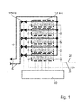
- FIG. 1 schematically shows a thermal storage with any number of memory cells 12a-e.
- Storage media are accommodated in the memory cells 12a-e, wherein the storage media in the individual memory cells 12a-e may differ in their transition temperatures / phase change temperatures.
- a first cooling line 16 is received, through which a first coolant is guided.
- the first cooling lines 16 are each connected to valves 18a-e, via which the supply or the circulation of the first coolant into or to the respective memory cells 12a-e can be controlled.
- a second cooling line 20 is further included, which leads a second coolant to discharge the memory cells 12a-e.
- valves 18a-e are connected to a controller 10.
- temperature measuring devices are included, which determine the temperature of each recorded therein storage media and transmitted to the controller 10.
- the temperature measuring devices are schematically indicated by the dotted line in FIG FIG. 1 shown.
- the controller 10 can determine on the basis of the temperature recorded by the temperature measuring device Whether the storage medium accommodated in the respective memory cell 12a-e is below or above the reversal temperature / phase change temperature of the storage medium. From this, the controller 10 can also determine the state of charge of the respective memory cells 12a-e.
- the temperature, determined by a temperature measuring device, of a storage medium in a selected storage cell 12a-e is below the changeover temperature / phase change temperature of the storage medium, then that storage cell 12a-e is charged. However, if the determined temperature is above the reversal temperature / phase change temperature of the storage medium accommodated in the respective memory cell 12a-e, then the respective memory cell 12a-e is discharged.
- the first coolant is fed via the valves 18a-e and the first cooling lines 16 into the memory cells 12a-e in order to cool the storage medium accommodated therein.
- the supply is controlled by the controller 10 via the opening and closing of the valves 18a-e.
- the supply of the first coolant takes place as shown by the arrow 26.
- the first coolant is brought to a certain temperature, for example, in a chiller, not shown, and then fed via the valves 18a-e to the memory cells 12a-e.
- a second cooling line 20 is also accommodated analogously to the first cooling lines 16, wherein a second coolant is guided in the second cooling lines 20.
- the memory cells 12a-e are discharged.
- the supply of the second coolant takes place as indicated by the arrow 28.
- the controller 10 can determine the (loading) state of charge of the thermal storage, consisting of the individual memory cells 12a-e, by detecting and evaluating the individual states "charged” / "discharged” of the respective memory cells 12a-e. Furthermore, it can be determined via the controller 10, to which memory cells 12a-e the first coolant is supplied.
Landscapes
- Engineering & Computer Science (AREA)
- Physics & Mathematics (AREA)
- Thermal Sciences (AREA)
- Mechanical Engineering (AREA)
- General Engineering & Computer Science (AREA)
- Chemical & Material Sciences (AREA)
- Combustion & Propulsion (AREA)
- Debugging And Monitoring (AREA)
- Devices That Are Associated With Refrigeration Equipment (AREA)
Abstract
Description
- Die vorliegende Erfindung betrifft eine Einrichtung zur Bestimmung des Ladezustands eines thermischen Speichers.
- Aus dem Stand der Technik sind verschiedene Kühleinrichtungen mit einem Kältespeicher bekannt. In diesen Kältespeichern wird ein Kühlmittel bevorratet, um dieses entweder später einem Verdampfer zuzuführen oder zum Kühlen eines weiteren Kühlmittels zu verwenden. Jedoch ergibt sich bei diesen Kältespeichern das Problem der Bestimmung des Ladezustands des Kältespeichers. Bei kleineren Einrichtungen wie beispielsweise Kühlschränken, sind solche Vorhersagen bzw. Bestimmungen nicht in dem Maße relevant wie bei begehbaren Kühlräumen, da der relativ kleine zu kühlende Raum durch konstruktive Maßnahmen für eine bestimmte Zeit die Temperatur in dem Raum unter einem bestimmten Grenzwert halten kann. Dazu ist beispielsweise das Gehäuse mit entsprechenden Kältespeichern und Materialien ausgestaltet.
-
DE 27 26 954 A1 offenbart ein Tiefkühlgerät mit einer elektrisch angetriebenen Kältemaschine und einem Kältespeicher, wobei der Kältespeicher ein Latentwärmespeicher ist. Die Kältemaschine wird von einem Steuergerät in Abhängigkeit des Stromtarifs und/oder der Tageszeit eingeschaltet und bei einer Temperatur unterhalb des Gefrierpunktes des Kältespeichers abgeschaltet. Hierzu ist eine Temperaturmesseinrichtung vorgesehen. -
DE 10 2011 003 441 A1 offenbart einen Latentwärmespeicher mit einer Ladezustandsanzeige. Der Latentwärmespeicher kann eine Vielzahl von Speicherbehältern aufweisen, in welchen ein Latentwärmespeichermaterial enthalten ist, wobei das Latentwärmespeichermaterial in den einzelnen Speicherbehältern über eine gemeinsame Wärmetauschereinrichtung kühlbar ist. Jeder der Speicherbehälter weist eine Druckmesseinrichtung auf, die den Druck in den Speicherbehältern bestimmt. Zur Druckbestimmung wird eine bestimmte Messgasmenge in den Speicherbehälter eingebracht, bis ein Druckmessgerät einen bestimmten Druck feststellt. Über vorher bestimmte Gasvolumen in den Speicherbehältern im beladenen und entladenen Zustand wird dann der Ladezustand bestimmt. -
US 6,481,216 B2 offenbart eine Kühlanlage mit drei in Reihe geschalteten Speichereinheiten, durch welche ein Fluid geführt wird. -
US 5,598,712 offenbart eine Kühlanlage mit Latentwärmespeichern, wobei in einer Ausführungsform eine Vielzahl von Wassertanks vorgesehen ist, in denen gekühltes Wasser und Eis enthalten ist, wobei die Wassertanks mit einer Temperaturmesseinrichtung verbunden sind. - Aufgabe der vorliegenden Erfindung ist es jedoch, eine Einrichtung zur Bestimmung des Ladezustands eines thermischen Speichers für einen zu kühlenden, begehbaren Raum anzugeben, wobei der thermische Speicher aus einer Vielzahl von Speicherzellen besteht.
- Die Aufgabe löst die Erfindung durch die in Anspruch 1 angegebenen Merkmale. Vorteilhafte Weiterbildungen der Erfindung sind in Unteransprüchen im Detail angegeben.
- Bei einer erfindungsgemäßen Einrichtung zur Bestimmung des Ladezustands eines thermischen Speichers für einen zu kühlenden, begehbaren Raum, aufweisend eine beliebige Anzahl von Speicherzellen, in denen ein Speichermedium aufgenommen ist, wobei die in den Speicherzellen aufgenommenen Speichermedien unterschiedliche Umschlagstemperaturen/Phasenwechseltemperaturen aufweisen, ist in/an den einzelnen Speicherzellen jeweils eine Temperaturmesseinrichtung angeordnet, die die Temperatur des Speichermediums in der jeweiligen Speicherzelle erfasst und an die Einrichtung übermittelt.
- Dadurch, dass in den einzelnen Speicherzellen Speichermedien mit unterschiedlichen Umschlags-/Phasenwechseltemperaturen aufgenommen sind, wobei diese Umschlags-/Phasenwechseltemperaturen der Einrichtung bekannt und in der Einrichtung hinterlegt sind, wird über die in/an den einzelnen Speicherzellen angeordneten Temperaturmesseinrichtungen eine einfache Ladezustandsbestimmung des thermischen Speichers bereitgestellt. Der Gesamtladezustand des thermischen Speichers ergibt sich dabei aus den einzelnen Speicherzuständen der jeweiligen Speicherzellen. Im einfachsten Fall wird für jede Speicherzelle ermittelt, ob die jeweilige Temperatur der jeweiligen Speicherzelle über oder unter der Umschlagstemperatur/Phasenwechseltemperatur des in der jeweiligen Speicherzelle aufgenommenen Speichermediums liegt. Ferner kann durch die Einrichtung eine Vorhersage gemacht werden, welche Kühlleistung zu einem bestimmten Zeitpunkt von dem thermischen Speicher zur Verfügung steht. Da der Einrichtung die Menge der Speichermedien in den jeweiligen Speicherzellen sowie deren Umschlagstemperatur/Phasenwechseltemperatur bekannt sind, kann sie über die Bestimmung des Zustands "geladen"/"nicht geladen" der einzelnen Speicherzellen eine Prognose für die aufbringbare Kühlleistung eines Kühlmittels liefern.
- In den Speicherzellen kann eine erste Kühlleitung angeordnet sein, in der ein erstes Kühlmittel zum Kühlen des Speichermediums zuführbar ist, und die ersten Kühlleitungen der Speicherzellen können mit einer Vorrichtung zum wahlweisen Zuführen des ersten Kühlmittels verbunden sein, wobei in den Kühlzellen eine zweite Kühlleitung angeordnet ist, wobei die zweiten Kühlleitungen über eine weitere Vorrichtung mit einem Verdampfer zum Verdampfen eines zweiten in den zweiten Kühlleitungen geführten Kühlmittels verbunden sind.
- Über die Vorrichtung kann den jeweiligen Speicherzellen über die ersten Kühlleitungen das erste Kühlmittel zum Kühlen der Speichermedien zugeführt werden, wobei die in den jeweiligen Speicherzellen aufgenommenen ersten Kühlleitungen über die Vorrichtung beispielsweise mit einer Kältemaschine verbunden sind. Über die zweiten Kühlleitungen, die ebenfalls in den jeweiligen Speicherzellen aufgenommen sind, und über die weitere Vorrichtung kann dem Verdampfer das zweite Kühlmittel mit der Temperatur zugeführt werden, welche in dem zu kühlenden Raum benötigt wird. Die Vorrichtungen können dabei gezielt die Zufuhr des ersten und des zweiten Kühlmittels zu den jeweiligen Speicherzellen steuern. Da in den Speicherzellen das zweite Kühlmittel auf verschiedene Temperaturen abkühlbar ist, kann auch über eine Reihen- oder Parallelschaltung ein breites Spektrum an einzustellenden Temperaturen für den zu kühlenden Raum durch entsprechende Kühlung mittels Zuführung des zweiten Kühlmittels zu bestimmten Speicherzellen erreicht werden.
- Die Einrichtung kann weiter eine Steuerung aufweisen, welche das Laden/Entladen des thermischen Speichers steuert, wobei die Steuerung die Zu- und Abfuhr des ersten Kühlmittels zu den Speicherzellen und die Zu- und Abfuhr des zweiten Kühlmittels zu dem Verdampfer in Abhängigkeit der von den Temperaturmesseinrichtungen erfassten Temperaturen der einzelnen Speicherzellen steuert.
- So kann die Zufuhr des ersten Kühlmittels in Abhängigkeit der Temperatur des Speichermediums in den Speicherzellen und die Zuführung des zweiten Kühlmittels aus den Speicherzellen in Abhängigkeit der Temperatur in dem zu kühlenden, begehbaren Raum sowie des Ladezustandes der Speicherzellen erfolgen. Das heißt, dass über die weitere Vorrichtung dem Verdampfer nur dann das zweite Kühlmittel aus den Speicherzellen zuführbar sein kann, wenn das Speichermedium in den jeweiligen Speicherzellen eine Temperatur aufweist, die unterhalb ihrer Umschlagstemperatur/Phasenwechseltemperatur liegt.
- Ferner kann über die Vorrichtung den einzelnen Speicherzellen nur dann das erste Kühlmittel zuführbar sein, wenn die Temperatur des Speichermediums in den jeweiligen Speicherzellen über der Umschlagstemperatur/Phasenwechseltemperatur der jeweiligen Speichermedien liegt.
- Die Speichermedien in den einzelnen Speicherzellen können dabei ein Phasenwechselmaterial sein. Bei einem Phasenwechselmaterial ist durch den Phasenwechsel die Speicherung einer großen Menge an thermischer Energie möglich. Dies führt in vorteilhafter Weise zu einer Verkleinerung der jeweiligen Speicherzellen.
- Die Erfindung lässt sich besonders wirtschaftlich realisieren in Verbindung mit thermischen Speichern, die eine Speicherkapazität von ≥4 kWh aufweisen. Die Speicherkapazität nach oben ist nicht begrenzt. Speicher mit einer Kapazität von 50 kWh und mehr können ebenfalls zur Anwendung kommen.
- Das Phasenwechselmaterial kann ein Gemisch aus Wasser und Salzen oder Alkoholen sein, dessen Phasenwechseltemperatur sich durch dessen Gemischzusammensetzung und/oder Gemischkonzentration unterscheidet.
- Weitere Ziele, Merkmale, Vorteile und Anwendungsmöglichkeiten ergeben sich aus der nachfolgenden Beschreibung von nicht einschränkend zu verstehenden Ausführungsbeispielen mit Bezug auf die zugehörigen Zeichnungen. Dabei bilden alle beschriebenen und/oder bildlich dargestellten Merkmale für sich oder in beliebiger Kombination den hier offenbarten Gegenstand, auch unabhängig von ihrer Gruppierung in den Ansprüchen oder deren Rückbeziehungen. Die Abmessungen und Proportionen der in den Figuren dargestellten Komponenten sind hierbei nicht unbedingt maßstäblich; sie können bei zu implementierenden Ausführungsformen vom Veranschaulichten abweichen.
- In den Zeichnungen zeigt:
- Figur 1
- eine schematische Ansicht eines thermischen Speichers mit einer Vielzahl von Speicherzellen.
-
Figur 1 zeigt schematisch einen thermischen Speicher mit einer beliebigen Anzahl von Speicherzellen 12a-e. In den Speicherzellen 12a-e sind Speichermedien aufgenommen, wobei sich die Speichermedien in den einzelnen Speicherzellen 12a-e in ihren Umschlagstemperaturen/Phasenwechseltemperaturen unterscheiden können. Ferner ist in den Speicherzellen 12a-e eine erste Kühlleitung 16 aufgenommen, durch welche ein erstes Kühlmittel geführt ist. Die ersten Kühlleitungen 16 sind jeweils mit Ventilen 18a-e verbunden, über die die Zufuhr bzw. das Umwälzen des ersten Kühlmittels in bzw. zu den jeweiligen Speicherzellen 12a-e gesteuert werden kann. - In den Speicherzellen 12a-e ist weiter eine zweite Kühlleitung 20 aufgenommen, die ein zweites Kühlmittel führt, um die Speicherzellen 12a-e zu entladen.
- Die Ventile 18a-e sind mit einer Steuerung 10 verbunden.
- In/an den einzelnen Speicherzellen 12a-e sind Temperaturmesseinrichtungen aufgenommen, welche die Temperatur der jeweils darin aufgenommenen Speichermedien ermitteln und an die Steuerung 10 übertragen. Dazu sind die Temperaturmessvorrichtungen schematisch durch die gepunktete Linie in
Figur 1 dargestellt. - Da in der Steuerung 10 hinterlegt ist, welches Speichermedium in den jeweiligen Speicherzellen 12a-e aufgenommen ist, bzw. welche Umschlagstemperatur/Phasenwechseltemperatur das in den jeweiligen Speicherzellen 12a - 12e aufgenommene Speichermedium aufweist, kann die Steuerung 10 anhand der von der Temperaturmesseinrichtung aufgenommenen Temperatur ermitteln, ob das in der jeweiligen Speicherzelle 12a-e aufgenommene Speichermedium unter oder über der Umschlagstemperatur/Phasenwechseltemperatur des Speichermediums liegt. Daraus kann die Steuerung 10 auch den Ladezustand der jeweiligen Speicherzellen 12a-e bestimmen.
- Liegt die von einer Temperaturmesseinrichtung ermittelte Temperatur eines Speichermediums in einer ausgewählten Speicherzelle 12a-e unter der Umschlagstemperatur/ Phasenwechseltemperatur des Speichermediums, so ist diejenige Speicherzelle 12a-e geladen. Liegt die ermittelte Temperatur jedoch über der Umschlagstemperatur/Phasenwechseltemperatur des in der jeweiligen Speicherzelle 12a-e aufgenommenen Speichermediums, so ist die jeweilige Speicherzelle 12a-e entladen.
- Das erste Kühlmittel wird über die Ventile 18a-e und die ersten Kühlleitungen 16 in die Speicherzellen 12a-e geführt, um das darin aufgenommene Speichermedium zu kühlen. Die Zufuhr wird über das Öffnen und Schließen der Ventile 18a-e durch die Steuerung 10 geregelt. Die Zuführung des ersten Kühlmittels erfolgt dabei wie durch den Pfeil 26 dargestellt. Das erste Kühlmittel wird beispielsweise in einer nicht dargestellten Kältemaschine auf eine bestimmte Temperatur gebracht und dann über die Ventile 18a-e den Speicherzellen 12a-e zugeführt.
- In den Speicherzellen 12a-e ist analog zu den ersten Kühlleitungen 16 auch jeweils eine zweite Kühlleitung 20 aufgenommen, wobei in den zweiten Kühlleitungen 20 ein zweites Kühlmittel geführt wird. Mittels des zweiten Kühlmittels werden die Speicherzellen 12a-e entladen. Die Zuführung des zweiten Kühlmittels erfolgt dabei wie durch den Pfeil 28 angedeutet.
- Die Steuerung 10 kann den (Be-)Ladezustand des thermischen Speichers, bestehend aus den einzelnen Speicherzellen 12a-e, ermitteln, indem die einzelnen Zustände "geladen"/"entladen" der jeweiligen Speicherzellen 12a-e erfasst und ausgewertet werden. Ferner kann über die Steuerung 10 festgelegt werden, zu welchen Speicherzellen 12a-e das erste Kühlmittel zugeführt wird.
-
- 10
- Steuerung
- 12a-e
- Speicherzelle
- 16
- erste Kühlleitung
- 18a-e
- Ventile / Durchflussregelung
- 20
- zweite Kühlleitung
- 26
- Strömungsrichtung erstes Kühlmittel
- 28
- Strömungsrichtung zweites Kühlmittel
Claims (7)
- Einrichtung zur Bestimmung des Ladezustands eines thermischen Speichers für einen zu kühlenden, begehbaren Raum, aufweisend eine beliebige Anzahl von Speicherzellen (12a-e), in denen ein Speichermedium aufgenommen ist, wobei die in den Speicherzellen (12a-e) aufgenommenen Speichermedien unterschiedliche Umschlagstemperaturen/Phasenwechseltemperaturen aufweisen und in/an den einzelnen Speicherzellen (12a-e) Temperaturmesseinrichtungen angeordnet sind, die die Temperatur der Speichermedien und somit den Ladezustand erfassen und der Einrichtung übermitteln.
- Einrichtung nach Anspruch 1, wobei in den Speicherzellen (12a-e) eine erste Kühlleitung (16) angeordnet ist, in der ein erstes Kühlmittel zum Kühlen des Speichermediums zuführbar ist, und die ersten Kühlleitungen (16) der Speicherzellen (12a-e) mit Ventilen zur Durchflussregelung (18a-e) zum wahlweisen Zuführen des ersten Kühlmittels verbunden sind und in den Speicherzellen (12a - 12e) eine zweite Kühlleitung (20) angeordnet ist, wobei über die zweiten Kühlleitungen (20) die Speicherzellen (12a-e) entladen werden.
- Einrichtung nach Anspruch 2, wobei die Einrichtung eine Steuerung (10) aufweist, welche das Laden/Entladen des thermischen Speichers steuert, wobei die Steuerung (10) die Zu- und Abfuhr des ersten Kühlmittels zu den Speicherzellen (12a-e) und die Zu- und Abfuhr des zweiten Kühlmittels in Abhängigkeit der von den Temperaturmesseinrichtungen erfassten Temperaturen steuert.
- Einrichtung nach Anspruch 3, wobei die Zuführung des ersten Kühlmittels in Abhängigkeit der Temperatur des Speichermediums in den Speicherzellen (12a-e) und die Zuführung des zweiten Kühlmittels aus den Speicherzellen (12a-e) in Abhängigkeit der Temperatur in dem zu kühlenden, begehbaren Raum sowie des Ladezustandes der Speicherzellen (12a-e) erfolgt.
- Einrichtung nach einem der Ansprüche 2 bis 4, wobei über die Ventile zur Durchflussregelung (18a-e) den einzelnen Speicherzellen (12a-e) nur dann das erste Kühlmittel zuführbar ist, wenn die Temperatur des Speichermediums in den jeweiligen Speicherzellen (12a-e) über der Umschlagstemperatur/Phasenwechseltemperatur liegt.
- Einrichtung nach einem der Ansprüche 1 bis 5, wobei die Speichermedien in den einzelnen Speicherzellen (12a-e) Phasenwechselmaterialien sind.
- Thermischer Speicher nach Anspruch 7, dadurch g e - kennzeichnet, dass er eine Speicherkapazität von ≥ 4 kWh aufweist.
Priority Applications (1)
| Application Number | Priority Date | Filing Date | Title |
|---|---|---|---|
| PL13184425T PL2713122T3 (pl) | 2012-09-27 | 2013-09-13 | Urządzenie do określania stanu załadowania segmentowanego zasobnika termicznego |
Applications Claiming Priority (1)
| Application Number | Priority Date | Filing Date | Title |
|---|---|---|---|
| DE202012103718U DE202012103718U1 (de) | 2012-09-27 | 2012-09-27 | Einrichtung zur Bestimmung des Ladezustands eines segmentierten thermischen Speichers |
Publications (3)
| Publication Number | Publication Date |
|---|---|
| EP2713122A2 true EP2713122A2 (de) | 2014-04-02 |
| EP2713122A3 EP2713122A3 (de) | 2016-10-05 |
| EP2713122B1 EP2713122B1 (de) | 2020-08-19 |
Family
ID=47665689
Family Applications (1)
| Application Number | Title | Priority Date | Filing Date |
|---|---|---|---|
| EP13184425.0A Active EP2713122B1 (de) | 2012-09-27 | 2013-09-13 | Einrichtung zur bestimmung des ladezustands eines segmentierten thermischen speichers |
Country Status (5)
| Country | Link |
|---|---|
| EP (1) | EP2713122B1 (de) |
| DE (1) | DE202012103718U1 (de) |
| ES (1) | ES2827475T3 (de) |
| PL (1) | PL2713122T3 (de) |
| PT (1) | PT2713122T (de) |
Families Citing this family (2)
| Publication number | Priority date | Publication date | Assignee | Title |
|---|---|---|---|---|
| AT518791B1 (de) * | 2016-12-14 | 2018-01-15 | Ait Austrian Inst Tech Gmbh | Verfahren zum bestimmen eines ladezustandes eines latentwärmespeichers |
| AT524238B1 (de) * | 2021-02-17 | 2022-04-15 | Univ Wien Tech | Verfahren zur Ermittlung des Ladezustandes eines Phasenwechselspeichers |
Citations (4)
| Publication number | Priority date | Publication date | Assignee | Title |
|---|---|---|---|---|
| DE2726954A1 (de) | 1977-06-15 | 1979-01-04 | Walter Holzer | Tiefkuehlgeraet mit kaeltespeicher |
| US5598712A (en) | 1992-02-28 | 1997-02-04 | Kabushiki Kaisha Toshiba | Latent heat accumulation system |
| US6481216B2 (en) | 1999-09-22 | 2002-11-19 | The Coca Cola Company | Modular eutectic-based refrigeration system |
| DE102011003441A1 (de) | 2011-02-01 | 2012-08-02 | ZAE Bayern Bayerisches Zentrum für angewandte Energieforschung e.V. | Verfahren zur Bestimmung des Ladezustandes eines Latentwärmespeichers und Latentwärmespeicher mit einer derartigen Ladezustandsanzeige |
Family Cites Families (4)
| Publication number | Priority date | Publication date | Assignee | Title |
|---|---|---|---|---|
| JP2005326078A (ja) * | 2004-05-14 | 2005-11-24 | Matsushita Electric Ind Co Ltd | ヒートポンプ給湯装置 |
| GB0808930D0 (en) * | 2008-05-16 | 2008-06-25 | Sunamp Ltd | Energy Storage system |
| GB0919934D0 (en) * | 2009-11-16 | 2009-12-30 | Sunamp Ltd | Energy storage systems |
| JP5604190B2 (ja) * | 2010-06-24 | 2014-10-08 | パナソニック株式会社 | 蓄熱システム |
-
2012
- 2012-09-27 DE DE202012103718U patent/DE202012103718U1/de not_active Expired - Lifetime
-
2013
- 2013-09-13 PL PL13184425T patent/PL2713122T3/pl unknown
- 2013-09-13 EP EP13184425.0A patent/EP2713122B1/de active Active
- 2013-09-13 PT PT131844250T patent/PT2713122T/pt unknown
- 2013-09-13 ES ES13184425T patent/ES2827475T3/es active Active
Patent Citations (4)
| Publication number | Priority date | Publication date | Assignee | Title |
|---|---|---|---|---|
| DE2726954A1 (de) | 1977-06-15 | 1979-01-04 | Walter Holzer | Tiefkuehlgeraet mit kaeltespeicher |
| US5598712A (en) | 1992-02-28 | 1997-02-04 | Kabushiki Kaisha Toshiba | Latent heat accumulation system |
| US6481216B2 (en) | 1999-09-22 | 2002-11-19 | The Coca Cola Company | Modular eutectic-based refrigeration system |
| DE102011003441A1 (de) | 2011-02-01 | 2012-08-02 | ZAE Bayern Bayerisches Zentrum für angewandte Energieforschung e.V. | Verfahren zur Bestimmung des Ladezustandes eines Latentwärmespeichers und Latentwärmespeicher mit einer derartigen Ladezustandsanzeige |
Also Published As
| Publication number | Publication date |
|---|---|
| DE202012103718U1 (de) | 2013-01-03 |
| PT2713122T (pt) | 2020-09-30 |
| ES2827475T3 (es) | 2021-05-21 |
| EP2713122B1 (de) | 2020-08-19 |
| EP2713122A3 (de) | 2016-10-05 |
| PL2713122T3 (pl) | 2021-03-08 |
Similar Documents
| Publication | Publication Date | Title |
|---|---|---|
| EP2831401B1 (de) | Verfahren und system zur wärmeübertragung für ein fahrzeug | |
| DE102014206770A1 (de) | Batteriekühleinrichtung und zugehöriges Betriebsverfahren | |
| EP2336700B1 (de) | Speichervorrichtung und Verfahren zu deren Betrieb | |
| DE202010007146U1 (de) | Elektrofahrzeug | |
| WO2011000826A1 (de) | Verfahren zur kühlung von batteriepacks und in module unterteiltes batteriepack | |
| WO2017102449A1 (de) | Verfahren zum temperieren eines energiesystems | |
| DE202010001201U1 (de) | Kühlsystem für die Batterie eines Elektrofahrzeugs | |
| EP2713122B1 (de) | Einrichtung zur bestimmung des ladezustands eines segmentierten thermischen speichers | |
| DE202012103715U1 (de) | Einrichtung zur Bestimmung des Ladezustands eines thermischen Speichers | |
| EP3619483B1 (de) | Kühlmöbel mit speicher, kühlsystem und verfahren zum steuern eines kühlmöbels mit einem speicher | |
| EP2713130A2 (de) | Thermischer Speicher für Kälteanlagen | |
| DE102012025192A1 (de) | Verfahren und Vorrichtung zur Vorkonditionierung von Latentwärmespeicherelementen | |
| DE102015106382A1 (de) | Batterietemperierungsvorrichtung sowie deren Verwendung, Batteriesystem und Fahrzeug mit einem solchen, sowie Verfahren zum Heizen und/oder Kühlen einer Batterie | |
| WO2012143226A2 (de) | Latentwärmespeichereinrichtung und betriebsverfahren für eine latentwärmespeichereinrichtung | |
| DE102018005503A1 (de) | Vorrichtung zum Unterkühlen von verflüssigten Gasen | |
| DE102009021543A1 (de) | Temperiersystem | |
| EP2713120B1 (de) | Thermischer Speicher für begehbare Kühlräume | |
| DE102010038773A1 (de) | Batterie-Kühlsystem | |
| DE112014005303B4 (de) | Anordnung und Verfahren zum Steuern der Temperatur eines Stromspeichersystems in einem Fahrzeug | |
| DE102005035017A1 (de) | Wärmeübertrager zur Kühlung von Ladeluft | |
| DE112015003065T5 (de) | Verfahren zum Betreiben einer Vorrichtung zur Wärmebehandlung eines Kraftfahrzeugfahrgastraums | |
| DE102015009256A1 (de) | Festbettkältespeicher und Verfahren zur Speicherung von thermischer Energie | |
| DE102014117149A1 (de) | Dezentrale Anlage für die Klimatisierung von Aufenthaltsräumen mit einem raumseitigen Anlagenteil und einem außenseitigen Anlagenteil | |
| DE588566C (de) | Kuehlanlage, deren Kaelteverwendungsstellen von einer Kaelteerzeugungsstelle aus durch einen Kaeltetraeger mit Kaelte versorgt werden und bei der ein fuer alle Kaelteverwendungsstellen gemeinsamer Kaeltespeicher vorhanden ist | |
| DE19938725C1 (de) | Latentkälte-Speicherverfahren und Latentkälte-Speicher für ein Kaltwassernetz |
Legal Events
| Date | Code | Title | Description |
|---|---|---|---|
| PUAI | Public reference made under article 153(3) epc to a published international application that has entered the european phase |
Free format text: ORIGINAL CODE: 0009012 |
|
| AK | Designated contracting states |
Kind code of ref document: A2 Designated state(s): AL AT BE BG CH CY CZ DE DK EE ES FI FR GB GR HR HU IE IS IT LI LT LU LV MC MK MT NL NO PL PT RO RS SE SI SK SM TR |
|
| AX | Request for extension of the european patent |
Extension state: BA ME |
|
| RAP1 | Party data changed (applicant data changed or rights of an application transferred) |
Owner name: VIESSMANN KUEHLSYSTEME GMBH |
|
| PUAL | Search report despatched |
Free format text: ORIGINAL CODE: 0009013 |
|
| AK | Designated contracting states |
Kind code of ref document: A3 Designated state(s): AL AT BE BG CH CY CZ DE DK EE ES FI FR GB GR HR HU IE IS IT LI LT LU LV MC MK MT NL NO PL PT RO RS SE SI SK SM TR |
|
| AX | Request for extension of the european patent |
Extension state: BA ME |
|
| RIC1 | Information provided on ipc code assigned before grant |
Ipc: F25D 11/00 20060101ALI20160901BHEP Ipc: F25D 16/00 20060101AFI20160901BHEP |
|
| STAA | Information on the status of an ep patent application or granted ep patent |
Free format text: STATUS: REQUEST FOR EXAMINATION WAS MADE |
|
| 17P | Request for examination filed |
Effective date: 20170404 |
|
| RBV | Designated contracting states (corrected) |
Designated state(s): AL AT BE BG CH CY CZ DE DK EE ES FI FR GB GR HR HU IE IS IT LI LT LU LV MC MK MT NL NO PL PT RO RS SE SI SK SM TR |
|
| RAP1 | Party data changed (applicant data changed or rights of an application transferred) |
Owner name: VIESSMANN KUEHLSYSTEME GMBH |
|
| STAA | Information on the status of an ep patent application or granted ep patent |
Free format text: STATUS: EXAMINATION IS IN PROGRESS |
|
| 17Q | First examination report despatched |
Effective date: 20190322 |
|
| GRAP | Despatch of communication of intention to grant a patent |
Free format text: ORIGINAL CODE: EPIDOSNIGR1 |
|
| STAA | Information on the status of an ep patent application or granted ep patent |
Free format text: STATUS: GRANT OF PATENT IS INTENDED |
|
| INTG | Intention to grant announced |
Effective date: 20200330 |
|
| RIN1 | Information on inventor provided before grant (corrected) |
Inventor name: ROEMER, SIEGFRIED Inventor name: GEBELEIN, BERND |
|
| GRAS | Grant fee paid |
Free format text: ORIGINAL CODE: EPIDOSNIGR3 |
|
| GRAA | (expected) grant |
Free format text: ORIGINAL CODE: 0009210 |
|
| STAA | Information on the status of an ep patent application or granted ep patent |
Free format text: STATUS: THE PATENT HAS BEEN GRANTED |
|
| AK | Designated contracting states |
Kind code of ref document: B1 Designated state(s): AL AT BE BG CH CY CZ DE DK EE ES FI FR GB GR HR HU IE IS IT LI LT LU LV MC MK MT NL NO PL PT RO RS SE SI SK SM TR |
|
| REG | Reference to a national code |
Ref country code: GB Ref legal event code: FG4D Free format text: NOT ENGLISH |
|
| REG | Reference to a national code |
Ref country code: CH Ref legal event code: EP |
|
| REG | Reference to a national code |
Ref country code: DE Ref legal event code: R082 Ref document number: 502013015030 Country of ref document: DE Representative=s name: DIE PATENTERIE GBR, DE |
|
| REG | Reference to a national code |
Ref country code: DE Ref legal event code: R096 Ref document number: 502013015030 Country of ref document: DE |
|
| REG | Reference to a national code |
Ref country code: AT Ref legal event code: REF Ref document number: 1304395 Country of ref document: AT Kind code of ref document: T Effective date: 20200915 |
|
| REG | Reference to a national code |
Ref country code: IE Ref legal event code: FG4D Free format text: LANGUAGE OF EP DOCUMENT: GERMAN |
|
| REG | Reference to a national code |
Ref country code: PT Ref legal event code: SC4A Ref document number: 2713122 Country of ref document: PT Date of ref document: 20200930 Kind code of ref document: T Free format text: AVAILABILITY OF NATIONAL TRANSLATION Effective date: 20200924 |
|
| REG | Reference to a national code |
Ref country code: FI Ref legal event code: FGE |
|
| REG | Reference to a national code |
Ref country code: SE Ref legal event code: TRGR |
|
| REG | Reference to a national code |
Ref country code: NL Ref legal event code: FP |
|
| REG | Reference to a national code |
Ref country code: LT Ref legal event code: MG4D Ref country code: NO Ref legal event code: T2 Effective date: 20200819 |
|
| PG25 | Lapsed in a contracting state [announced via postgrant information from national office to epo] |
Ref country code: BG Free format text: LAPSE BECAUSE OF FAILURE TO SUBMIT A TRANSLATION OF THE DESCRIPTION OR TO PAY THE FEE WITHIN THE PRESCRIBED TIME-LIMIT Effective date: 20201119 Ref country code: HR Free format text: LAPSE BECAUSE OF FAILURE TO SUBMIT A TRANSLATION OF THE DESCRIPTION OR TO PAY THE FEE WITHIN THE PRESCRIBED TIME-LIMIT Effective date: 20200819 Ref country code: GR Free format text: LAPSE BECAUSE OF FAILURE TO SUBMIT A TRANSLATION OF THE DESCRIPTION OR TO PAY THE FEE WITHIN THE PRESCRIBED TIME-LIMIT Effective date: 20201120 Ref country code: LT Free format text: LAPSE BECAUSE OF FAILURE TO SUBMIT A TRANSLATION OF THE DESCRIPTION OR TO PAY THE FEE WITHIN THE PRESCRIBED TIME-LIMIT Effective date: 20200819 |
|
| PG25 | Lapsed in a contracting state [announced via postgrant information from national office to epo] |
Ref country code: LV Free format text: LAPSE BECAUSE OF FAILURE TO SUBMIT A TRANSLATION OF THE DESCRIPTION OR TO PAY THE FEE WITHIN THE PRESCRIBED TIME-LIMIT Effective date: 20200819 Ref country code: RS Free format text: LAPSE BECAUSE OF FAILURE TO SUBMIT A TRANSLATION OF THE DESCRIPTION OR TO PAY THE FEE WITHIN THE PRESCRIBED TIME-LIMIT Effective date: 20200819 Ref country code: IS Free format text: LAPSE BECAUSE OF FAILURE TO SUBMIT A TRANSLATION OF THE DESCRIPTION OR TO PAY THE FEE WITHIN THE PRESCRIBED TIME-LIMIT Effective date: 20201219 |
|
| PG25 | Lapsed in a contracting state [announced via postgrant information from national office to epo] |
Ref country code: RO Free format text: LAPSE BECAUSE OF FAILURE TO SUBMIT A TRANSLATION OF THE DESCRIPTION OR TO PAY THE FEE WITHIN THE PRESCRIBED TIME-LIMIT Effective date: 20200819 Ref country code: SM Free format text: LAPSE BECAUSE OF FAILURE TO SUBMIT A TRANSLATION OF THE DESCRIPTION OR TO PAY THE FEE WITHIN THE PRESCRIBED TIME-LIMIT Effective date: 20200819 Ref country code: CZ Free format text: LAPSE BECAUSE OF FAILURE TO SUBMIT A TRANSLATION OF THE DESCRIPTION OR TO PAY THE FEE WITHIN THE PRESCRIBED TIME-LIMIT Effective date: 20200819 Ref country code: DK Free format text: LAPSE BECAUSE OF FAILURE TO SUBMIT A TRANSLATION OF THE DESCRIPTION OR TO PAY THE FEE WITHIN THE PRESCRIBED TIME-LIMIT Effective date: 20200819 Ref country code: EE Free format text: LAPSE BECAUSE OF FAILURE TO SUBMIT A TRANSLATION OF THE DESCRIPTION OR TO PAY THE FEE WITHIN THE PRESCRIBED TIME-LIMIT Effective date: 20200819 |
|
| REG | Reference to a national code |
Ref country code: DE Ref legal event code: R097 Ref document number: 502013015030 Country of ref document: DE |
|
| REG | Reference to a national code |
Ref country code: ES Ref legal event code: FG2A Ref document number: 2827475 Country of ref document: ES Kind code of ref document: T3 Effective date: 20210521 |
|
| PG25 | Lapsed in a contracting state [announced via postgrant information from national office to epo] |
Ref country code: AL Free format text: LAPSE BECAUSE OF FAILURE TO SUBMIT A TRANSLATION OF THE DESCRIPTION OR TO PAY THE FEE WITHIN THE PRESCRIBED TIME-LIMIT Effective date: 20200819 Ref country code: MC Free format text: LAPSE BECAUSE OF FAILURE TO SUBMIT A TRANSLATION OF THE DESCRIPTION OR TO PAY THE FEE WITHIN THE PRESCRIBED TIME-LIMIT Effective date: 20200819 |
|
| PLBE | No opposition filed within time limit |
Free format text: ORIGINAL CODE: 0009261 |
|
| STAA | Information on the status of an ep patent application or granted ep patent |
Free format text: STATUS: NO OPPOSITION FILED WITHIN TIME LIMIT |
|
| PG25 | Lapsed in a contracting state [announced via postgrant information from national office to epo] |
Ref country code: SK Free format text: LAPSE BECAUSE OF FAILURE TO SUBMIT A TRANSLATION OF THE DESCRIPTION OR TO PAY THE FEE WITHIN THE PRESCRIBED TIME-LIMIT Effective date: 20200819 Ref country code: LU Free format text: LAPSE BECAUSE OF NON-PAYMENT OF DUE FEES Effective date: 20200913 |
|
| 26N | No opposition filed |
Effective date: 20210520 |
|
| PG25 | Lapsed in a contracting state [announced via postgrant information from national office to epo] |
Ref country code: SI Free format text: LAPSE BECAUSE OF FAILURE TO SUBMIT A TRANSLATION OF THE DESCRIPTION OR TO PAY THE FEE WITHIN THE PRESCRIBED TIME-LIMIT Effective date: 20200819 Ref country code: IE Free format text: LAPSE BECAUSE OF NON-PAYMENT OF DUE FEES Effective date: 20200913 |
|
| PG25 | Lapsed in a contracting state [announced via postgrant information from national office to epo] |
Ref country code: TR Free format text: LAPSE BECAUSE OF FAILURE TO SUBMIT A TRANSLATION OF THE DESCRIPTION OR TO PAY THE FEE WITHIN THE PRESCRIBED TIME-LIMIT Effective date: 20200819 Ref country code: MT Free format text: LAPSE BECAUSE OF FAILURE TO SUBMIT A TRANSLATION OF THE DESCRIPTION OR TO PAY THE FEE WITHIN THE PRESCRIBED TIME-LIMIT Effective date: 20200819 Ref country code: CY Free format text: LAPSE BECAUSE OF FAILURE TO SUBMIT A TRANSLATION OF THE DESCRIPTION OR TO PAY THE FEE WITHIN THE PRESCRIBED TIME-LIMIT Effective date: 20200819 |
|
| PG25 | Lapsed in a contracting state [announced via postgrant information from national office to epo] |
Ref country code: MK Free format text: LAPSE BECAUSE OF FAILURE TO SUBMIT A TRANSLATION OF THE DESCRIPTION OR TO PAY THE FEE WITHIN THE PRESCRIBED TIME-LIMIT Effective date: 20200819 |
|
| PGFP | Annual fee paid to national office [announced via postgrant information from national office to epo] |
Ref country code: NO Payment date: 20220922 Year of fee payment: 10 |
|
| PGFP | Annual fee paid to national office [announced via postgrant information from national office to epo] |
Ref country code: BE Payment date: 20220922 Year of fee payment: 10 |
|
| P01 | Opt-out of the competence of the unified patent court (upc) registered |
Effective date: 20230512 |
|
| PGFP | Annual fee paid to national office [announced via postgrant information from national office to epo] |
Ref country code: NL Payment date: 20230921 Year of fee payment: 11 Ref country code: GB Payment date: 20230920 Year of fee payment: 11 Ref country code: FI Payment date: 20230920 Year of fee payment: 11 Ref country code: AT Payment date: 20230919 Year of fee payment: 11 |
|
| PGFP | Annual fee paid to national office [announced via postgrant information from national office to epo] |
Ref country code: SE Payment date: 20230921 Year of fee payment: 11 Ref country code: PT Payment date: 20230831 Year of fee payment: 11 Ref country code: PL Payment date: 20230828 Year of fee payment: 11 Ref country code: FR Payment date: 20230922 Year of fee payment: 11 Ref country code: DE Payment date: 20230830 Year of fee payment: 11 |
|
| PGFP | Annual fee paid to national office [announced via postgrant information from national office to epo] |
Ref country code: ES Payment date: 20231002 Year of fee payment: 11 |
|
| PGFP | Annual fee paid to national office [announced via postgrant information from national office to epo] |
Ref country code: IT Payment date: 20230927 Year of fee payment: 11 Ref country code: CH Payment date: 20231001 Year of fee payment: 11 |