EP2713078B1 - Poulie entraînée en résine de nylon - Google Patents
Poulie entraînée en résine de nylon Download PDFInfo
- Publication number
- EP2713078B1 EP2713078B1 EP13186625.3A EP13186625A EP2713078B1 EP 2713078 B1 EP2713078 B1 EP 2713078B1 EP 13186625 A EP13186625 A EP 13186625A EP 2713078 B1 EP2713078 B1 EP 2713078B1
- Authority
- EP
- European Patent Office
- Prior art keywords
- pulley
- ball nut
- ball
- torque transmitting
- transmitting assembly
- Prior art date
- Legal status (The legal status is an assumption and is not a legal conclusion. Google has not performed a legal analysis and makes no representation as to the accuracy of the status listed.)
- Active
Links
- 239000004677 Nylon Substances 0.000 title claims description 6
- 229920001778 nylon Polymers 0.000 title claims description 6
- 239000011347 resin Substances 0.000 title claims description 4
- 229920005989 resin Polymers 0.000 title claims description 4
- 238000000034 method Methods 0.000 claims description 12
- 238000004519 manufacturing process Methods 0.000 claims description 4
- 229920000642 polymer Polymers 0.000 claims description 3
- 239000011521 glass Substances 0.000 claims description 2
- 230000008878 coupling Effects 0.000 claims 1
- 238000010168 coupling process Methods 0.000 claims 1
- 238000005859 coupling reaction Methods 0.000 claims 1
- 230000033001 locomotion Effects 0.000 description 7
- 239000000463 material Substances 0.000 description 4
- 229910000831 Steel Inorganic materials 0.000 description 3
- 230000000712 assembly Effects 0.000 description 3
- 238000000429 assembly Methods 0.000 description 3
- 238000004891 communication Methods 0.000 description 3
- 238000003754 machining Methods 0.000 description 3
- 230000007246 mechanism Effects 0.000 description 3
- 239000010959 steel Substances 0.000 description 3
- 230000005540 biological transmission Effects 0.000 description 2
- 230000014759 maintenance of location Effects 0.000 description 2
- 239000004952 Polyamide Substances 0.000 description 1
- 230000000295 complement effect Effects 0.000 description 1
- 238000010276 construction Methods 0.000 description 1
- 230000009977 dual effect Effects 0.000 description 1
- 230000013011 mating Effects 0.000 description 1
- 229920002647 polyamide Polymers 0.000 description 1
- 230000002441 reversible effect Effects 0.000 description 1
- 238000003466 welding Methods 0.000 description 1
Images


Classifications
-
- B—PERFORMING OPERATIONS; TRANSPORTING
- B62—LAND VEHICLES FOR TRAVELLING OTHERWISE THAN ON RAILS
- B62D—MOTOR VEHICLES; TRAILERS
- B62D5/00—Power-assisted or power-driven steering
- B62D5/04—Power-assisted or power-driven steering electrical, e.g. using an electric servo-motor connected to, or forming part of, the steering gear
- B62D5/0442—Conversion of rotational into longitudinal movement
- B62D5/0445—Screw drives
- B62D5/0448—Ball nuts
-
- B—PERFORMING OPERATIONS; TRANSPORTING
- B62—LAND VEHICLES FOR TRAVELLING OTHERWISE THAN ON RAILS
- B62D—MOTOR VEHICLES; TRAILERS
- B62D5/00—Power-assisted or power-driven steering
- B62D5/04—Power-assisted or power-driven steering electrical, e.g. using an electric servo-motor connected to, or forming part of, the steering gear
- B62D5/0421—Electric motor acting on or near steering gear
- B62D5/0424—Electric motor acting on or near steering gear the axes of motor and final driven element of steering gear, e.g. rack, being parallel
-
- F—MECHANICAL ENGINEERING; LIGHTING; HEATING; WEAPONS; BLASTING
- F16—ENGINEERING ELEMENTS AND UNITS; GENERAL MEASURES FOR PRODUCING AND MAINTAINING EFFECTIVE FUNCTIONING OF MACHINES OR INSTALLATIONS; THERMAL INSULATION IN GENERAL
- F16H—GEARING
- F16H25/00—Gearings comprising primarily only cams, cam-followers and screw-and-nut mechanisms
- F16H25/18—Gearings comprising primarily only cams, cam-followers and screw-and-nut mechanisms for conveying or interconverting oscillating or reciprocating motions
- F16H25/20—Screw mechanisms
- F16H25/22—Screw mechanisms with balls, rollers, or similar members between the co-operating parts; Elements essential to the use of such members
- F16H25/2204—Screw mechanisms with balls, rollers, or similar members between the co-operating parts; Elements essential to the use of such members with balls
- F16H25/2214—Screw mechanisms with balls, rollers, or similar members between the co-operating parts; Elements essential to the use of such members with balls with elements for guiding the circulating balls
-
- F—MECHANICAL ENGINEERING; LIGHTING; HEATING; WEAPONS; BLASTING
- F16—ENGINEERING ELEMENTS AND UNITS; GENERAL MEASURES FOR PRODUCING AND MAINTAINING EFFECTIVE FUNCTIONING OF MACHINES OR INSTALLATIONS; THERMAL INSULATION IN GENERAL
- F16H—GEARING
- F16H55/00—Elements with teeth or friction surfaces for conveying motion; Worms, pulleys or sheaves for gearing mechanisms
- F16H55/02—Toothed members; Worms
- F16H55/17—Toothed wheels
- F16H55/171—Toothed belt pulleys
-
- F—MECHANICAL ENGINEERING; LIGHTING; HEATING; WEAPONS; BLASTING
- F16—ENGINEERING ELEMENTS AND UNITS; GENERAL MEASURES FOR PRODUCING AND MAINTAINING EFFECTIVE FUNCTIONING OF MACHINES OR INSTALLATIONS; THERMAL INSULATION IN GENERAL
- F16H—GEARING
- F16H55/00—Elements with teeth or friction surfaces for conveying motion; Worms, pulleys or sheaves for gearing mechanisms
- F16H55/32—Friction members
- F16H55/36—Pulleys
- F16H55/48—Pulleys manufactured exclusively or in part of non-metallic material, e.g. plastics
-
- F—MECHANICAL ENGINEERING; LIGHTING; HEATING; WEAPONS; BLASTING
- F16—ENGINEERING ELEMENTS AND UNITS; GENERAL MEASURES FOR PRODUCING AND MAINTAINING EFFECTIVE FUNCTIONING OF MACHINES OR INSTALLATIONS; THERMAL INSULATION IN GENERAL
- F16H—GEARING
- F16H25/00—Gearings comprising primarily only cams, cam-followers and screw-and-nut mechanisms
- F16H25/18—Gearings comprising primarily only cams, cam-followers and screw-and-nut mechanisms for conveying or interconverting oscillating or reciprocating motions
- F16H25/20—Screw mechanisms
- F16H2025/2062—Arrangements for driving the actuator
- F16H2025/2081—Parallel arrangement of drive motor to screw axis
-
- F—MECHANICAL ENGINEERING; LIGHTING; HEATING; WEAPONS; BLASTING
- F16—ENGINEERING ELEMENTS AND UNITS; GENERAL MEASURES FOR PRODUCING AND MAINTAINING EFFECTIVE FUNCTIONING OF MACHINES OR INSTALLATIONS; THERMAL INSULATION IN GENERAL
- F16H—GEARING
- F16H25/00—Gearings comprising primarily only cams, cam-followers and screw-and-nut mechanisms
- F16H25/18—Gearings comprising primarily only cams, cam-followers and screw-and-nut mechanisms for conveying or interconverting oscillating or reciprocating motions
- F16H25/20—Screw mechanisms
- F16H2025/2062—Arrangements for driving the actuator
- F16H2025/2096—Arrangements for driving the actuator using endless flexible members
-
- F—MECHANICAL ENGINEERING; LIGHTING; HEATING; WEAPONS; BLASTING
- F16—ENGINEERING ELEMENTS AND UNITS; GENERAL MEASURES FOR PRODUCING AND MAINTAINING EFFECTIVE FUNCTIONING OF MACHINES OR INSTALLATIONS; THERMAL INSULATION IN GENERAL
- F16H—GEARING
- F16H55/00—Elements with teeth or friction surfaces for conveying motion; Worms, pulleys or sheaves for gearing mechanisms
- F16H55/02—Toothed members; Worms
- F16H55/06—Use of materials; Use of treatments of toothed members or worms to affect their intrinsic material properties
Definitions
- the following description relates to a torque transmitting assembly, and in particular, a pulley and ball nut of a motor.
- a torque transmitted from an electric motor by a belt is typically done via a steel driven pulley attached to a ball nut with several screw fasteners.
- the screw fasteners may be received through the steel driven pulley and received in threaded or tapped bores of the ball nut.
- machining features such as threaded or tapped holes into the ball nut and machining mating features into the steel pulley are costly.
- the driven pulley is assembled to the ball nut by driving the fasteners through the driven pulley hub and into the ball nut. Sufficient processing time is required to assemble the driven pulley to the ball nut using this process.
- another aspect of the ball nut assembly process involves assembling a centering ring onto the ball nut.
- the centering ring has a dual function: to concentrically locate the driven pulley on the ball nut and to retain ball returns of the ball nut within the ball nut.
- a torque transmitting assembly according to claim 1.
- the assembly includes a ball nut having an outer diameter and keyway slot therein, and a pulley positioned on the ball nut.
- the pulley includes a cylindrical outer surface, a bore extending through the pulley such that the pulley includes an inner surface, and at least one torque member formed on the inner surface and projecting radially inward to be received by the keyway slot.
- a steering system in a not claimed embodiment of the present invention, there is provided a steering system.
- the steering system includes a motor, a shaft rotatably coupled to the motor, a first pulley coupled to the shaft, a ball screw, and a ball nut assembly operatively associated with the ball screw and the first pulley to transmit torque therebetween.
- the ball nut assembly includes a ball nut and a second pulley coupled to the ball nut.
- the second pulley includes an inner surface defining a bore, a cut-out formed in the inner surface, and at least one torque member extending from the inner surface into the bore.
- a method of fabricating a ball nut assembly includes providing a ball nut having a keyway slot, and forming a pulley having an inner surface defining a bore, a cut-out formed in the inner surface, and a torque member extending radially inward from the inner surface.
- the keyway slot is configured to receive the torque member therein.
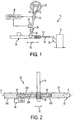
- FIGS. 1 and 2 show a steering system 10 for use in a vehicle (not shown).
- Steering system 10 allows the operator of the vehicle to control the direction of the vehicle through the manipulation of a steering column 12, which is mechanically connected to road wheels 14 (only one shown).
- Steering column 12 includes an upper steering shaft 16 and a lower steering shaft 18.
- a hand wheel 20 is disposed at upper steering shaft 16 and is positioned so that the operator can apply a rotational force to steering column 12.
- a torque sensor 22 and a position sensor 24 are located at upper steering column shaft 16 to detect the turning angle of hand wheel 20.
- torque sensor 22 and position sensor 24 are in electronic communication with a controller 26.
- a column universal joint 28 couples upper steering column shaft 16 to lower steering column shaft 18, which is secured at one end to column universal joint 28, and to a steering gear assembly 30 at the other end.
- Gear assembly 30 includes an elongate rack 32 having longitudinal axis A along which it linearly translates.
- rack 32 The opposed axial ends of rack 32 are coupled to the vehicle's road wheels 14 through steering linkage that includes tie rods 34 (only one shown) each secured to rack 32 at one end, and to one of a pair of steering knuckles 36 (only one shown) at the other end.
- Steering gear assembly 30 further includes a pinion gear 38 in mechanical connection with rack 32.
- Pinion gear 38 is positioned to make contact with a matching toothed portion 40 of rack 32 that extends along a segment of rack 32.
- Pinion gear 38 has teeth that are engaged with teeth of matching toothed portion 40.
- Rack 32 also includes an axially extending segment along which is provided generally cylindrical ball screw portion 44 centered about axis A. Toothed portion 40 and a ball screw portion 44 are integrated into rack 32, and ball screw 44 is in mechanical communication with a reversible servomotor 46.
- Ball screw 44 and motor 46 may be located axially along rack 32 on either first side 200 or opposite second side 202 of toothed portion 40. In addition, motor 46 may be located radially either on top side 204 or bottom side 206 of rack 32. Actuation of motor 46 is controlled by controller 26.
- pinion gear 38 When the vehicle operator turns hand wheel 20, a rotational force is applied to steering column 12 and pinion gear 38 is accordingly rotated.
- the movement of pinion gear 38 causes axial movement of rack 32 in the direction of arrows 52, which in turn manipulates tie rods 34 and knuckles 36 in order to reposition road wheels 14.
- pinion gear 38 and matching tooth portion 40 convert rotary motion of hand wheel 20 into linear motion of rack 32.
- motor 46 is energized and provides power assist to the movement of rack 32 through ball screw 44, thereby aiding in the steering of the vehicle.
- motor 46 is in operable communication with ball screw 44 through a ball nut assembly 48 rotatably disposed about ball screw 44.
- a shaft 50 extends from motor 46 substantially in parallel with rack 32, and is rotated in one of two opposite angular direction when motor 46 is energized.
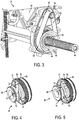
- a driving pulley 54 is rotatably fixed to shaft 50.
- a flexible, endless drive belt 58 is wrapped around driving pulley 54 such that a belt inner surface 60 is in frictional contact with pulley 54.
- Belt 58 also wraps around a driven pulley 62 defining the outer circumference of ball nut assembly 48 such that belt inner surface 60 is in frictional contact with driven pulley 62.
- Driven pulley 62 defines a central axis C about which it is radially centered and includes the radially outer surface of a generally cylindrical ball nut 66.
- motor 46 When motor 46 is actuated, movement of belt 58 linking pulleys 54 and 62 causes ball nut 66 to rotate about central axis C and ball screw 44.
- ball nut assembly 48 includes ball nut 66, a ball guide 68, a retainer 70, and a retaining nut 72.
- Ball nut 66 includes a first groove 74 to receive at least a portion of ball guide 68, a second groove 76 to receive at least a portion of retainer 70, and a keyway slot 78 configured to receive at least a portion of driven pulley 62, as is described herein in more detail.
- Ball guide 68 recirculates balls located in ball grooves (not shown) formed between ball screw 44 and ball nut 66.
- retainer 70 is a biasing member and is located in groove 76 to facilitate preloading driven pulley 62 to press against a ball screw bearing 80 (see FIG. 8 ).
- Retaining nut 72 is threaded into the steering system housing and abuts against bearing 80 to form a groove 82 therebetween.
- An elastomeric isolator member or O-ring 84 is positioned within groove 82 (see FIG. 8 ).
- FIG. 6 is a perspective view of driven pulley 62
- FIGS. 7 and 8 illustrate driven pulley 62 assembled onto ball nut 66.
- driven pulley 62 is positioned on ball nut 66 and concentrically locates itself by being pressed onto an outer diameter of ball nut 66.
- Retainer 70 and/or retaining nut 72 facilitate locating pulley 62 onto ball nut 66.
- other locating mechanisms may be used in addition to, or in place of, the mechanisms described above.
- pulley 62 is a generally cylindrical shape and includes an outer surface 86 and an inner surface 88. Outer surface includes a plurality of teeth 89 circumferentially spaced from each other to engage belt 58, and inner surface 88 is a generally smooth bore surface that includes at least one torque member 90 extending radially inward therefrom.
- torque member 90 is configured to extend into keyway slot 78 to facilitate transferring torque between ball nut 66 and driven pulley 62.
- pulley 62 includes a cut-out 92 formed in a portion 93 of inner surface 88, which is shaped and configured to provide proper clearance for ball guide 68 when inserting pulley 62 onto ball nut 66.
- Cut-out 92 is also shaped and configured to provide proper interference and retention of ball guide 68.
- cut-out 92 includes a centerpoint 95 and has a radius that is smaller than a radius of bore 94 defined by inner surface 88 and a centerpoint 97.
- Driven pulley 62 may be made from, for example, a polymer, including polyamides such as nylon resin.
- pulley 62 is fabricated from glass filled nylon. It is understood that these examples are non-exhaustive and non-limiting. Other suitable materials are envisioned as well for the construction of pulley 62. For example, other compressible materials, which may be pressed onto ball nut 66, may be suitable for the pulley 62.
- a flange 96 is coupled to driven pulley to complement a second flange 98 such that belt 58 is at least partially contained between flanges 96 and 98.
- Flange 96 may be fabricated from the same material as pulley 62 or may be fabricated from any suitable different material. Further, flange 96 may be coupled to pulley 62 by any suitable process (e.g., sonic welding). Alternatively, flange 96 may be formed integrally with driven pulley 62.
- a section 100 of driven pulley 62 deforms when pulley 62 is pressed onto ball nut 66.
- the deformation results in a substantially flat portion 102 along pulley outer surface 86 in the region of section 100.
- substantially flat portion refers to a portion that may present a flat or un-curved shape, or may be a portion that is deformed so that a radius of curvature is increased in that region.
- Power assist steering system 10 illustrated in FIGS. 1 and 2 includes a mechanical connection, via rack and pinion gear set 42, between hand wheel 20 and rack 32.
- rack and pinion gear set 42 there is no such direct mechanical connection between hand wheel 20 and rack 32.
- similarly sensed rotational movement of hand wheel 20 by the driver (and/or a signal form an equivalent driver control device) is input into controller 26 while motor 46 provides the necessary force to manipulate rack 32.
- the system described herein may be similarly utilized in steer-by-wire systems.
- a method of fabricating a ball nut assembly includes forming ball nut 66 with ball guide 68, first groove 68, second groove 70, and keyway slot 78. Grooves 68 and 70 and keyway slot 78 may be machined in a separate process.
- the method further includes forming driven pulley 62 from a polymer such as nylon resin. Pulley 62 is formed with teeth 89 on outer surface 86, cut-out 92, and at least one torque member 90 extending radially into bore 94 from inner surface 88.
- Retainer 70 may be pressed into second groove 70, and pulley 62 is assembled onto ball nut 66 such that torque member 90 is inserted into keyway slot 78 and cut-out 92 slides over ball guide 68.
- Section 100 may then be pressed such that section 100 deforms and produces flat portion 102 and secures pulley 62 to ball nut 66.
Landscapes
- Engineering & Computer Science (AREA)
- General Engineering & Computer Science (AREA)
- Mechanical Engineering (AREA)
- Chemical & Material Sciences (AREA)
- Combustion & Propulsion (AREA)
- Transportation (AREA)
- Manufacturing & Machinery (AREA)
- Power Steering Mechanism (AREA)
- Physics & Mathematics (AREA)
- Electromagnetism (AREA)
- Thermal Sciences (AREA)
- Transmission Devices (AREA)
Claims (12)
- Assemblage de transmission de couple, comprenant :un écrou à recirculation de billes (66) ayant un diamètre extérieur et une rainure à clavette (78) en lui-même ; etune poulie (62) positionnée sur l'écrou à recirculation de billes (66), la poulie (62) ayant une surface extérieure cylindrique (86), un perçage (94) s'étendant à travers la poulie (62) de telle façon que la poulie (62) inclut une surface intérieure (88), et au moins un élément de transmission de couple (90) formé sur la surface intérieure (88) et en projection radialement vers l'intérieur pour être reçu par la rainure à clavette (78),caractérisé en ce queune section (100) de la poulie (62) se déforme quand la poulie (62) est pressée sur l'écrou à recirculation de billes (66), la déformation ayant pour résultat une portion sensiblement plane (102) le long d'une surface extérieure (86) de la poulie (62) dans la région de la section (100).
- Assemblage de transmission de couple selon la revendication 1, dans lequel la poulie (62) est réalisée en un polymère.
- Assemblage de transmission de couple selon la revendication 1, dans lequel la poulie (62) est réalisée en un nylon chargé de verre.
- Assemblage de transmission de couple selon la revendication 1, dans lequel le perçage (94) comprend une première section ayant un premier rayon et une seconde section ayant un second rayon, le premier rayon étant plus grand que le second rayon.
- Assemblage de transmission de couple selon la revendication 4, dans lequel la surface intérieure de la poulie (88) est configurée pour se déformer dans la région de la seconde section lorsqu'elle est pressée sur l'écrou à recirculation de billes (66) pour présenter la portion sensiblement plane (102) le long de la surface extérieure (86).
- Assemblage de transmission de couple selon la revendication 1, comprenant en outre une pluralité de dents (87) espacées circonférentiellement le long de la surface extérieure (86) de la poulie.
- Assemblage de transmission de couple selon la revendication 1, dans lequel la surface intérieure (88) est configurée pour retenir des retours de billes de l'écrou à recirculation de billes (66).
- Assemblage de transmission de couple (selon la revendication 1, dans lequel l'écrou à recirculation de billes (66) inclut un guide de billes (68) et une gorge (74) recevant au moins partiellement le guide de billes (68), et dans lequel la poulie (62) inclut une découpe (92) formée dans la surface intérieure (88), la découpe (92) assurant un jeu pour le guide de billes (68) quand la poulie (62) est positionnée sur l'écrou à recirculation de billes (66).
- Procédé de fabrication d'un assemblage à recirculation de billes, le procédé comprenant les étapes consistant à :fournir un écrou à recirculation de billes (66) ayant une rainure à clavette (78) ;former une poulie (62) ayant une surface intérieure (88) définissant un perçage (94), une découpe (92) formée dans la surface intérieure (88), et un élément transmetteur de couple (90) s'étendant radialement vers l'intérieur depuis la surface intérieure (88), de sorte que la rainure à clavette (78) est configurée pour recevoir l'élément transmetteur de couple (90) à l'intérieur ;insérer la poulie (66) sur l'écrou à recirculation de billes (66) de telle façon que l'élément transmetteur de couple (90) est au moins partiellement à l'intérieur de la rainure à clavette (78),caractérisé en ce queune section (100) de la poulie (62) est déformée quand la poulie (62) est pressée sur l'écrou à recirculation de billes (66), la déformation ayant pour résultat une portion sensiblement plane (102) le long d'une surface extérieure (86) de la poulie (62) dans la région de la section (100).
- Procédé selon la revendication 9, dans lequel l'étape de formation de la poulie (62) comprend en outre l'opération consistant à fabriquer la poulie (62) en résine de nylon.
- Procédé selon la revendication 9, comprenant en outre l'opération consistant à former une gorge (76) sur une extrémité de l'écrou à recirculation de billes (66), et à insérer un élément de retenue (70) dans la gorge (76).
- Procédé selon la revendication 9, comprenant en outre l'opération consistant à former une bride (96) et à coupler la bride (96) sur la poulie (62).
Applications Claiming Priority (2)
| Application Number | Priority Date | Filing Date | Title |
|---|---|---|---|
| US201261707117P | 2012-09-28 | 2012-09-28 | |
| US14/038,976 US9637164B2 (en) | 2012-09-28 | 2013-09-27 | Nylon resin driven pulley |
Publications (2)
| Publication Number | Publication Date |
|---|---|
| EP2713078A1 EP2713078A1 (fr) | 2014-04-02 |
| EP2713078B1 true EP2713078B1 (fr) | 2016-03-30 |
Family
ID=49303771
Family Applications (1)
| Application Number | Title | Priority Date | Filing Date |
|---|---|---|---|
| EP13186625.3A Active EP2713078B1 (fr) | 2012-09-28 | 2013-09-30 | Poulie entraînée en résine de nylon |
Country Status (4)
| Country | Link |
|---|---|
| US (3) | US9637164B2 (fr) |
| EP (1) | EP2713078B1 (fr) |
| CN (1) | CN103707922B (fr) |
| PL (1) | PL2713078T3 (fr) |
Cited By (1)
| Publication number | Priority date | Publication date | Assignee | Title |
|---|---|---|---|---|
| DE102016007542A1 (de) | 2016-06-22 | 2017-12-28 | Thyssenkrupp Ag | Kugelgewindetrieb einer elektromechanischen Servolenkung mit Umlenkkörper für eine Kugelrückführung |
Families Citing this family (13)
| Publication number | Priority date | Publication date | Assignee | Title |
|---|---|---|---|---|
| US9021910B2 (en) * | 2012-08-17 | 2015-05-05 | Steering Solutions Ip Holding Corporation | Ball-screw assembly isolator having compressible members |
| US9637164B2 (en) | 2012-09-28 | 2017-05-02 | Steering Solutions Ip Holding Corporation | Nylon resin driven pulley |
| KR101699993B1 (ko) * | 2012-10-05 | 2017-01-25 | 주식회사 만도 | 벨트 타입 전동식 파워 스티어링 기어의 풀리 구조 |
| US20150336605A1 (en) * | 2014-05-23 | 2015-11-26 | Steering Solutions Ip Holding Corporation | Steering system with tilted motor axis |
| CN107207035B (zh) * | 2015-02-03 | 2019-12-03 | 株式会社捷太格特 | 转向装置 |
| US10160479B2 (en) * | 2015-07-09 | 2018-12-25 | Steering Solutions Ip Holding Corporation | Eccentric adjustment retainer |
| KR101783100B1 (ko) * | 2015-10-05 | 2017-09-28 | 주식회사 만도 | 랙구동형 동력 보조 조향장치 |
| JP6837233B2 (ja) * | 2017-01-11 | 2021-03-03 | 日立Astemo株式会社 | パワーステアリング装置 |
| JP2018176815A (ja) | 2017-04-04 | 2018-11-15 | 株式会社ジェイテクト | ステアリング装置 |
| JP2018202919A (ja) | 2017-05-31 | 2018-12-27 | 株式会社ジェイテクト | ステアリング装置 |
| EP3557096B1 (fr) * | 2018-04-20 | 2022-04-13 | SFS Group International AG | Méthode de compensation d'équilibrage et entraînement à vis à bille comprenant un élément de transmission de forces dimensionné avec cette méthode |
| US10865862B2 (en) * | 2018-08-27 | 2020-12-15 | Hitachi Automotive Systems Americas, Inc. | Pulley and ball nut assembly |
| CN211343906U (zh) * | 2019-11-08 | 2020-08-25 | 全球传动科技股份有限公司 | 直线传动系统 |
Family Cites Families (9)
| Publication number | Priority date | Publication date | Assignee | Title |
|---|---|---|---|---|
| US4195862A (en) * | 1978-05-01 | 1980-04-01 | Shim-A-Line, Inc. | Camber adjusting shim arrangement |
| DE102007049114B4 (de) | 2007-10-12 | 2018-02-15 | Volkswagen Ag | Zahnriemenrad einer elektromechanischen Lenkung mit Kugelgewindemutter |
| WO2010033788A1 (fr) | 2008-09-19 | 2010-03-25 | Delphi Technologies, Inc. | Mécanisme rotatif vers linéaire présentant un isolant |
| DE102009046386A1 (de) * | 2009-11-04 | 2011-05-05 | Zf Lenksysteme Gmbh | Servolenkung |
| US8307940B2 (en) | 2010-03-15 | 2012-11-13 | Trw Automotive U.S. Llc | Electric power steering assembly |
| DE102010003105A1 (de) | 2010-03-22 | 2011-09-22 | Zf Lenksysteme Gmbh | Servolenkung |
| US8496552B2 (en) | 2010-09-14 | 2013-07-30 | Ford Global Technologies, Llc | Angled spoke pulley design |
| DE102010054134B3 (de) * | 2010-12-10 | 2012-04-12 | Thyssenkrupp Presta Ag | Kugelgewindetrieb |
| US9637164B2 (en) | 2012-09-28 | 2017-05-02 | Steering Solutions Ip Holding Corporation | Nylon resin driven pulley |
-
2013
- 2013-09-27 US US14/038,976 patent/US9637164B2/en active Active
- 2013-09-30 EP EP13186625.3A patent/EP2713078B1/fr active Active
- 2013-09-30 PL PL13186625.3T patent/PL2713078T3/pl unknown
- 2013-09-30 CN CN201310596461.5A patent/CN103707922B/zh active Active
-
2017
- 2017-03-22 US US15/465,817 patent/US10526006B2/en active Active
-
2019
- 2019-12-06 US US16/705,995 patent/US10981593B2/en active Active
Cited By (3)
| Publication number | Priority date | Publication date | Assignee | Title |
|---|---|---|---|---|
| DE102016007542A1 (de) | 2016-06-22 | 2017-12-28 | Thyssenkrupp Ag | Kugelgewindetrieb einer elektromechanischen Servolenkung mit Umlenkkörper für eine Kugelrückführung |
| WO2017220713A1 (fr) | 2016-06-22 | 2017-12-28 | Thyssenkrupp Presta Ag | Mécanisme de vis-écrou à billes d'une direction assistée électromécanique comportant des corps de déviation pour un retour des billes |
| US10913484B2 (en) | 2016-06-22 | 2021-02-09 | Thyssenkrupp Presta Ag | Ball screw drive of an electromechanical power steering device with deflecting bodies for a ball return |
Also Published As
| Publication number | Publication date |
|---|---|
| US10981593B2 (en) | 2021-04-20 |
| US9637164B2 (en) | 2017-05-02 |
| US20140090921A1 (en) | 2014-04-03 |
| CN103707922B (zh) | 2019-05-28 |
| US10526006B2 (en) | 2020-01-07 |
| EP2713078A1 (fr) | 2014-04-02 |
| US20200108855A1 (en) | 2020-04-09 |
| US20170190353A1 (en) | 2017-07-06 |
| CN103707922A (zh) | 2014-04-09 |
| PL2713078T3 (pl) | 2016-12-30 |
Similar Documents
| Publication | Publication Date | Title |
|---|---|---|
| US10981593B2 (en) | Nylon resin driven pulley | |
| EP2344372B1 (fr) | Mécanisme rotatif vers linéaire présentant un isolant | |
| EP3388309B1 (fr) | Système de direction | |
| US7377194B2 (en) | Worm gear mechanism and electric power steering apparatus equipped with the worm gear mechanism | |
| EP1783031B1 (fr) | Direction assistée de voiture avec transmission à courroie | |
| US6848534B2 (en) | Electric power steering apparatus | |
| CN107031700B (zh) | 转向装置 | |
| US10322744B2 (en) | Road wheel actuator assembly | |
| KR20130048837A (ko) | 랙구동형 조향장치 및 이를 구비한 랙구동형 동력 보조 조향장치 | |
| US20180186398A1 (en) | Steering device | |
| EP2946986A1 (fr) | Système de direction avec axe de moteur incliné | |
| KR101393166B1 (ko) | 랙구동형 동력 보조 조향장치 | |
| US20220379949A1 (en) | Steer by wire type steering apparatus | |
| KR101393253B1 (ko) | 전동식 조향장치의 동력 전달 부재 | |
| EP2128470B1 (fr) | Ensemble de couplage de rotor et d'anneau | |
| JP4930771B2 (ja) | 電動パワーステアリング装置 | |
| US20210261186A1 (en) | Steering system | |
| JP2005205923A (ja) | 電動式パワーステアリング装置 | |
| EP3088771B1 (fr) | Sous-ensemble d'arbre de vis sans fin | |
| KR20170019613A (ko) | 랙구동형 동력 보조 조향장치 | |
| CN114987601A (zh) | 用于机动车辆的机电齿条小齿轮式转向系统和用于生产这种齿条小齿轮式转向系统的方法 | |
| KR20130084418A (ko) | 랙구동형 동력 보조 조향장치 | |
| KR20180039515A (ko) | 랙구동형 동력 보조 조향장치 | |
| KR20110114898A (ko) | 전동식 동력조향장치의 종동부 어셈블리 |
Legal Events
| Date | Code | Title | Description |
|---|---|---|---|
| PUAI | Public reference made under article 153(3) epc to a published international application that has entered the european phase |
Free format text: ORIGINAL CODE: 0009012 |
|
| AK | Designated contracting states |
Kind code of ref document: A1 Designated state(s): AL AT BE BG CH CY CZ DE DK EE ES FI FR GB GR HR HU IE IS IT LI LT LU LV MC MK MT NL NO PL PT RO RS SE SI SK SM TR |
|
| AX | Request for extension of the european patent |
Extension state: BA ME |
|
| 17P | Request for examination filed |
Effective date: 20141002 |
|
| RBV | Designated contracting states (corrected) |
Designated state(s): AL AT BE BG CH CY CZ DE DK EE ES FI FR GB GR HR HU IE IS IT LI LT LU LV MC MK MT NL NO PL PT RO RS SE SI SK SM TR |
|
| 17Q | First examination report despatched |
Effective date: 20150126 |
|
| GRAP | Despatch of communication of intention to grant a patent |
Free format text: ORIGINAL CODE: EPIDOSNIGR1 |
|
| INTG | Intention to grant announced |
Effective date: 20150917 |
|
| GRAS | Grant fee paid |
Free format text: ORIGINAL CODE: EPIDOSNIGR3 |
|
| GRAA | (expected) grant |
Free format text: ORIGINAL CODE: 0009210 |
|
| AK | Designated contracting states |
Kind code of ref document: B1 Designated state(s): AL AT BE BG CH CY CZ DE DK EE ES FI FR GB GR HR HU IE IS IT LI LT LU LV MC MK MT NL NO PL PT RO RS SE SI SK SM TR |
|
| REG | Reference to a national code |
Ref country code: GB Ref legal event code: FG4D |
|
| REG | Reference to a national code |
Ref country code: CH Ref legal event code: EP |
|
| REG | Reference to a national code |
Ref country code: AT Ref legal event code: REF Ref document number: 785759 Country of ref document: AT Kind code of ref document: T Effective date: 20160415 |
|
| REG | Reference to a national code |
Ref country code: IE Ref legal event code: FG4D |
|
| REG | Reference to a national code |
Ref country code: DE Ref legal event code: R096 Ref document number: 602013005876 Country of ref document: DE |
|
| REG | Reference to a national code |
Ref country code: LT Ref legal event code: MG4D |
|
| PG25 | Lapsed in a contracting state [announced via postgrant information from national office to epo] |
Ref country code: FI Free format text: LAPSE BECAUSE OF FAILURE TO SUBMIT A TRANSLATION OF THE DESCRIPTION OR TO PAY THE FEE WITHIN THE PRESCRIBED TIME-LIMIT Effective date: 20160330 Ref country code: GR Free format text: LAPSE BECAUSE OF FAILURE TO SUBMIT A TRANSLATION OF THE DESCRIPTION OR TO PAY THE FEE WITHIN THE PRESCRIBED TIME-LIMIT Effective date: 20160701 Ref country code: HR Free format text: LAPSE BECAUSE OF FAILURE TO SUBMIT A TRANSLATION OF THE DESCRIPTION OR TO PAY THE FEE WITHIN THE PRESCRIBED TIME-LIMIT Effective date: 20160330 Ref country code: NO Free format text: LAPSE BECAUSE OF FAILURE TO SUBMIT A TRANSLATION OF THE DESCRIPTION OR TO PAY THE FEE WITHIN THE PRESCRIBED TIME-LIMIT Effective date: 20160630 |
|
| REG | Reference to a national code |
Ref country code: NL Ref legal event code: MP Effective date: 20160330 |
|
| REG | Reference to a national code |
Ref country code: AT Ref legal event code: MK05 Ref document number: 785759 Country of ref document: AT Kind code of ref document: T Effective date: 20160330 |
|
| PG25 | Lapsed in a contracting state [announced via postgrant information from national office to epo] |
Ref country code: RS Free format text: LAPSE BECAUSE OF FAILURE TO SUBMIT A TRANSLATION OF THE DESCRIPTION OR TO PAY THE FEE WITHIN THE PRESCRIBED TIME-LIMIT Effective date: 20160330 Ref country code: LT Free format text: LAPSE BECAUSE OF FAILURE TO SUBMIT A TRANSLATION OF THE DESCRIPTION OR TO PAY THE FEE WITHIN THE PRESCRIBED TIME-LIMIT Effective date: 20160330 Ref country code: LV Free format text: LAPSE BECAUSE OF FAILURE TO SUBMIT A TRANSLATION OF THE DESCRIPTION OR TO PAY THE FEE WITHIN THE PRESCRIBED TIME-LIMIT Effective date: 20160330 Ref country code: SE Free format text: LAPSE BECAUSE OF FAILURE TO SUBMIT A TRANSLATION OF THE DESCRIPTION OR TO PAY THE FEE WITHIN THE PRESCRIBED TIME-LIMIT Effective date: 20160330 |
|
| PG25 | Lapsed in a contracting state [announced via postgrant information from national office to epo] |
Ref country code: NL Free format text: LAPSE BECAUSE OF FAILURE TO SUBMIT A TRANSLATION OF THE DESCRIPTION OR TO PAY THE FEE WITHIN THE PRESCRIBED TIME-LIMIT Effective date: 20160330 |
|
| PG25 | Lapsed in a contracting state [announced via postgrant information from national office to epo] |
Ref country code: EE Free format text: LAPSE BECAUSE OF FAILURE TO SUBMIT A TRANSLATION OF THE DESCRIPTION OR TO PAY THE FEE WITHIN THE PRESCRIBED TIME-LIMIT Effective date: 20160330 Ref country code: IS Free format text: LAPSE BECAUSE OF FAILURE TO SUBMIT A TRANSLATION OF THE DESCRIPTION OR TO PAY THE FEE WITHIN THE PRESCRIBED TIME-LIMIT Effective date: 20160730 |
|
| PG25 | Lapsed in a contracting state [announced via postgrant information from national office to epo] |
Ref country code: PT Free format text: LAPSE BECAUSE OF FAILURE TO SUBMIT A TRANSLATION OF THE DESCRIPTION OR TO PAY THE FEE WITHIN THE PRESCRIBED TIME-LIMIT Effective date: 20160801 Ref country code: SM Free format text: LAPSE BECAUSE OF FAILURE TO SUBMIT A TRANSLATION OF THE DESCRIPTION OR TO PAY THE FEE WITHIN THE PRESCRIBED TIME-LIMIT Effective date: 20160330 Ref country code: AT Free format text: LAPSE BECAUSE OF FAILURE TO SUBMIT A TRANSLATION OF THE DESCRIPTION OR TO PAY THE FEE WITHIN THE PRESCRIBED TIME-LIMIT Effective date: 20160330 Ref country code: SK Free format text: LAPSE BECAUSE OF FAILURE TO SUBMIT A TRANSLATION OF THE DESCRIPTION OR TO PAY THE FEE WITHIN THE PRESCRIBED TIME-LIMIT Effective date: 20160330 Ref country code: ES Free format text: LAPSE BECAUSE OF FAILURE TO SUBMIT A TRANSLATION OF THE DESCRIPTION OR TO PAY THE FEE WITHIN THE PRESCRIBED TIME-LIMIT Effective date: 20160330 Ref country code: RO Free format text: LAPSE BECAUSE OF FAILURE TO SUBMIT A TRANSLATION OF THE DESCRIPTION OR TO PAY THE FEE WITHIN THE PRESCRIBED TIME-LIMIT Effective date: 20160330 Ref country code: CZ Free format text: LAPSE BECAUSE OF FAILURE TO SUBMIT A TRANSLATION OF THE DESCRIPTION OR TO PAY THE FEE WITHIN THE PRESCRIBED TIME-LIMIT Effective date: 20160330 |
|
| PG25 | Lapsed in a contracting state [announced via postgrant information from national office to epo] |
Ref country code: IT Free format text: LAPSE BECAUSE OF FAILURE TO SUBMIT A TRANSLATION OF THE DESCRIPTION OR TO PAY THE FEE WITHIN THE PRESCRIBED TIME-LIMIT Effective date: 20160330 Ref country code: BE Free format text: LAPSE BECAUSE OF FAILURE TO SUBMIT A TRANSLATION OF THE DESCRIPTION OR TO PAY THE FEE WITHIN THE PRESCRIBED TIME-LIMIT Effective date: 20160330 |
|
| REG | Reference to a national code |
Ref country code: DE Ref legal event code: R097 Ref document number: 602013005876 Country of ref document: DE |
|
| PG25 | Lapsed in a contracting state [announced via postgrant information from national office to epo] |
Ref country code: DK Free format text: LAPSE BECAUSE OF FAILURE TO SUBMIT A TRANSLATION OF THE DESCRIPTION OR TO PAY THE FEE WITHIN THE PRESCRIBED TIME-LIMIT Effective date: 20160330 |
|
| PLBE | No opposition filed within time limit |
Free format text: ORIGINAL CODE: 0009261 |
|
| STAA | Information on the status of an ep patent application or granted ep patent |
Free format text: STATUS: NO OPPOSITION FILED WITHIN TIME LIMIT |
|
| 26N | No opposition filed |
Effective date: 20170103 |
|
| PG25 | Lapsed in a contracting state [announced via postgrant information from national office to epo] |
Ref country code: MC Free format text: LAPSE BECAUSE OF FAILURE TO SUBMIT A TRANSLATION OF THE DESCRIPTION OR TO PAY THE FEE WITHIN THE PRESCRIBED TIME-LIMIT Effective date: 20160330 |
|
| REG | Reference to a national code |
Ref country code: CH Ref legal event code: PL |
|
| PG25 | Lapsed in a contracting state [announced via postgrant information from national office to epo] |
Ref country code: SI Free format text: LAPSE BECAUSE OF FAILURE TO SUBMIT A TRANSLATION OF THE DESCRIPTION OR TO PAY THE FEE WITHIN THE PRESCRIBED TIME-LIMIT Effective date: 20160330 |
|
| REG | Reference to a national code |
Ref country code: IE Ref legal event code: MM4A |
|
| REG | Reference to a national code |
Ref country code: FR Ref legal event code: ST Effective date: 20170531 |
|
| PG25 | Lapsed in a contracting state [announced via postgrant information from national office to epo] |
Ref country code: IE Free format text: LAPSE BECAUSE OF NON-PAYMENT OF DUE FEES Effective date: 20160930 Ref country code: CH Free format text: LAPSE BECAUSE OF NON-PAYMENT OF DUE FEES Effective date: 20160930 Ref country code: LI Free format text: LAPSE BECAUSE OF NON-PAYMENT OF DUE FEES Effective date: 20160930 Ref country code: FR Free format text: LAPSE BECAUSE OF NON-PAYMENT OF DUE FEES Effective date: 20160930 |
|
| PG25 | Lapsed in a contracting state [announced via postgrant information from national office to epo] |
Ref country code: LU Free format text: LAPSE BECAUSE OF NON-PAYMENT OF DUE FEES Effective date: 20160930 |
|
| PG25 | Lapsed in a contracting state [announced via postgrant information from national office to epo] |
Ref country code: PL Free format text: LAPSE BECAUSE OF NON-PAYMENT OF DUE FEES Effective date: 20160930 |
|
| GBPC | Gb: european patent ceased through non-payment of renewal fee |
Effective date: 20170930 |
|
| PG25 | Lapsed in a contracting state [announced via postgrant information from national office to epo] |
Ref country code: HU Free format text: LAPSE BECAUSE OF FAILURE TO SUBMIT A TRANSLATION OF THE DESCRIPTION OR TO PAY THE FEE WITHIN THE PRESCRIBED TIME-LIMIT; INVALID AB INITIO Effective date: 20130930 Ref country code: CY Free format text: LAPSE BECAUSE OF FAILURE TO SUBMIT A TRANSLATION OF THE DESCRIPTION OR TO PAY THE FEE WITHIN THE PRESCRIBED TIME-LIMIT Effective date: 20160330 |
|
| PG25 | Lapsed in a contracting state [announced via postgrant information from national office to epo] |
Ref country code: MK Free format text: LAPSE BECAUSE OF FAILURE TO SUBMIT A TRANSLATION OF THE DESCRIPTION OR TO PAY THE FEE WITHIN THE PRESCRIBED TIME-LIMIT Effective date: 20160330 Ref country code: MT Free format text: LAPSE BECAUSE OF NON-PAYMENT OF DUE FEES Effective date: 20160930 |
|
| PG25 | Lapsed in a contracting state [announced via postgrant information from national office to epo] |
Ref country code: GB Free format text: LAPSE BECAUSE OF NON-PAYMENT OF DUE FEES Effective date: 20170930 Ref country code: BG Free format text: LAPSE BECAUSE OF FAILURE TO SUBMIT A TRANSLATION OF THE DESCRIPTION OR TO PAY THE FEE WITHIN THE PRESCRIBED TIME-LIMIT Effective date: 20160330 |
|
| PG25 | Lapsed in a contracting state [announced via postgrant information from national office to epo] |
Ref country code: TR Free format text: LAPSE BECAUSE OF FAILURE TO SUBMIT A TRANSLATION OF THE DESCRIPTION OR TO PAY THE FEE WITHIN THE PRESCRIBED TIME-LIMIT Effective date: 20160330 Ref country code: AL Free format text: LAPSE BECAUSE OF FAILURE TO SUBMIT A TRANSLATION OF THE DESCRIPTION OR TO PAY THE FEE WITHIN THE PRESCRIBED TIME-LIMIT Effective date: 20160330 |
|
| PGFP | Annual fee paid to national office [announced via postgrant information from national office to epo] |
Ref country code: DE Payment date: 20230927 Year of fee payment: 11 |