EP2712958A1 - Vorrichtung und Verfahren zur Herstellung einer Materialbahn - Google Patents
Vorrichtung und Verfahren zur Herstellung einer Materialbahn Download PDFInfo
- Publication number
- EP2712958A1 EP2712958A1 EP13198087.2A EP13198087A EP2712958A1 EP 2712958 A1 EP2712958 A1 EP 2712958A1 EP 13198087 A EP13198087 A EP 13198087A EP 2712958 A1 EP2712958 A1 EP 2712958A1
- Authority
- EP
- European Patent Office
- Prior art keywords
- fibrous web
- permeable
- press
- forming
- machine according
- Prior art date
- Legal status (The legal status is an assumption and is not a legal conclusion. Google has not performed a legal analysis and makes no representation as to the accuracy of the status listed.)
- Granted
Links
- 238000004519 manufacturing process Methods 0.000 title claims abstract description 13
- 238000003825 pressing Methods 0.000 claims abstract description 39
- 239000012530 fluid Substances 0.000 claims abstract description 12
- 239000004744 fabric Substances 0.000 claims description 17
- 238000001035 drying Methods 0.000 claims description 12
- 239000011248 coating agent Substances 0.000 claims description 9
- 238000000576 coating method Methods 0.000 claims description 9
- 239000002184 metal Substances 0.000 claims description 4
- 239000002131 composite material Substances 0.000 claims description 2
- 239000011087 paperboard Substances 0.000 claims description 2
- -1 spiral sieve Substances 0.000 claims 1
- 239000002657 fibrous material Substances 0.000 abstract description 6
- 238000000034 method Methods 0.000 abstract description 2
- 238000009499 grossing Methods 0.000 description 14
- 239000000123 paper Substances 0.000 description 4
- 238000013461 design Methods 0.000 description 3
- 238000011161 development Methods 0.000 description 3
- 230000035699 permeability Effects 0.000 description 2
- XLYOFNOQVPJJNP-UHFFFAOYSA-N water Substances O XLYOFNOQVPJJNP-UHFFFAOYSA-N 0.000 description 2
- 102100031952 Protein 4.1 Human genes 0.000 description 1
- 101710196266 Protein 4.1 Proteins 0.000 description 1
- 229920002472 Starch Polymers 0.000 description 1
- 238000005452 bending Methods 0.000 description 1
- 239000004918 carbon fiber reinforced polymer Substances 0.000 description 1
- 230000007423 decrease Effects 0.000 description 1
- 239000003292 glue Substances 0.000 description 1
- 238000013208 measuring procedure Methods 0.000 description 1
- 239000000049 pigment Substances 0.000 description 1
- 239000004033 plastic Substances 0.000 description 1
- 229920003023 plastic Polymers 0.000 description 1
- 238000012545 processing Methods 0.000 description 1
- 230000002787 reinforcement Effects 0.000 description 1
- 230000003252 repetitive effect Effects 0.000 description 1
- 238000000926 separation method Methods 0.000 description 1
- 235000019698 starch Nutrition 0.000 description 1
- 239000008107 starch Substances 0.000 description 1
- 239000000725 suspension Substances 0.000 description 1
- 238000012360 testing method Methods 0.000 description 1
- 238000004804 winding Methods 0.000 description 1
Images


Classifications
-
- D—TEXTILES; PAPER
- D21—PAPER-MAKING; PRODUCTION OF CELLULOSE
- D21F—PAPER-MAKING MACHINES; METHODS OF PRODUCING PAPER THEREON
- D21F9/00—Complete machines for making continuous webs of paper
- D21F9/003—Complete machines for making continuous webs of paper of the twin-wire type
- D21F9/006—Complete machines for making continuous webs of paper of the twin-wire type paper or board consisting of two or more layers
-
- D—TEXTILES; PAPER
- D21—PAPER-MAKING; PRODUCTION OF CELLULOSE
- D21F—PAPER-MAKING MACHINES; METHODS OF PRODUCING PAPER THEREON
- D21F11/00—Processes for making continuous lengths of paper, or of cardboard, or of wet web for fibre board production, on paper-making machines
- D21F11/02—Processes for making continuous lengths of paper, or of cardboard, or of wet web for fibre board production, on paper-making machines of the Fourdrinier type
- D21F11/04—Processes for making continuous lengths of paper, or of cardboard, or of wet web for fibre board production, on paper-making machines of the Fourdrinier type paper or board consisting on two or more layers
-
- D—TEXTILES; PAPER
- D21—PAPER-MAKING; PRODUCTION OF CELLULOSE
- D21F—PAPER-MAKING MACHINES; METHODS OF PRODUCING PAPER THEREON
- D21F3/00—Press section of machines for making continuous webs of paper
- D21F3/02—Wet presses
- D21F3/0272—Wet presses in combination with suction or blowing devices
Definitions
- the invention relates to a machine for producing a multilayer fibrous web, in particular a board web, having a forming region comprising at least two layer forming regions for forming the fibrous web layers for forming the multilayer fibrous web, and having a pressing region adjoining the forming region.
- the invention also relates to a method for producing a multilayer fibrous web, as well as the use of the machine.
- the document EP1780332 A1 describes a machine for producing a board web.
- the board web of 4 fibrous web layers, which are each formed in Lagenformier Schemeen, produced in the forming area.
- the further dewatering by roll pressing in a pressing area.
- the drying takes place in a subsequent drying section.
- a Yankee cylinder is provided within the dryer section.
- a broad nip calender is installed to further improve the smoothness of the board web. This is followed by a coating device for applying a stroke to one side of the board web, followed by final drying and reeling of the board web.
- the object of the present invention is to improve the known manufacturing process for a paper and board web in terms of their quality and its cost-effectiveness.
- Essential to the invention is that for dewatering a dewatering unit with a press zone, through which the fibrous web and / or a fibrous web position between a circumferential, permeable belt and a circumferential, permeable support belt is passed, is provided, and wherein the pressing zone is formed such that the permeable band, the fibrous web and / or a fibrous web ply and the permeable support band, at least on a part of the Length of the press zone, can be flowed through by a fluid and the pressing zone is formed by a permeable pressing member and a permeable counter element.
- the fibrous web is gently dewatered, wherein the applied mechanical dewatering pressure can be adjusted almost independent of the intensity of the flow through the fibrous web with the fluid.
- the strength values of the multilayer fibrous web in particular the splitting strength, are improved.
- the drainage is very volume-saving, so that the thickness of the fibrous web decreases less by the pressing process than in the known manufacturing processes. Since the thickness of the fibrous web substantially influences the mechanical strength, as for example in the case of a bending load, the mechanical strength of the fibrous web can be increased by the solution according to the invention or fiber material can be saved by reducing the basis weight with the same strength.
- the solution according to the invention makes it possible to produce a paper or board web, in particular a folding carton web with a high specific volume and at the same time good smoothness.
- the flow direction of the fluid is selected so that first the permeable pressing element, then the permeable band, the fibrous web or the fibrous web layer and then the permeable support band are flowed through.
- the permeable pressing element is preferably a mechanical pressing element for forming a mechanical pressure on the permeable band and thus on the fibrous web.
- the counter element is designed as a roller or a box with a curved or flat contact surface.
- the roller is preferably a suction roller.
- it has an internal suction box with one, preferably two or more suction zones. These extend essentially, as seen in the machine direction, to the length of the press zone.
- the suction roll can also be designed as a grooved or grooved and drilled roll.
- an external suction box may be provided for sucking the grooves. This results in an efficient flow guidance of the fluid through the press zone. Flow losses can be minimized.
- the permeable pressing element consists of a press belt and / or a press shoe. If only one press belt is used as the press element, then it is conceivable to use a further press element, for example in the form of a roller or a press shoe, within the press belt loop. Thus, the mechanical dewatering pressure can be increased locally within the press zone.
- the press shoe serves as a pressing element, it may be designed to be permeable or grooved and / or drilled in order to allow flow through the pressing zone with the fluid.
- the press belt consists of a screen mesh, a spiral screen, metal mesh, perforated metal strip or a band of composite material, such as carbon fiber reinforced plastic.
- the press belt has an air permeability of more than 100 cfm, in particular more than 200 cfm, where "cfm" indicates the cubic feet of air volume at a differential pressure of 125 Pa per square of the press belt in square feet per minute flows through the press belt.
- the measuring procedure is described in the TAPPI T251 standard.
- the area of the air permeability has the advantage that at a given differential pressure between the side facing away from the fibrous web side of the permeable support belt and the side facing away from the permeable belt side of the Pressbandes, a very high volume flow of fluid through the fibrous web can flow. Another advantage is that it keeps the mechanical pressure generated by the flow small.
- the press belt is designed so that a tensile stress of more than 30 kN / m, in particular of more than 40 kN / m, in particular of more than 45 kN / m in operation of the machine is possible.
- the dewatering unit is preferably configured so that the pressure on the fibrous web is less than 0.9 bar, in particular less than 0.5 bar, preferably less than 0.2 bar.
- the diameter of the counter element is advantageously greater than 1m, or the radius of curvature of the counter element is greater than 0.5m.
- the permeable tape may have a structured surface for structuring the fibrous web and / or at least one fibrous web layer. This is especially true for fibrous webs which only need to be smooth on one side or for fibrous web layers which form an inner fibrous web layer of the multilayer fibrous web. This allows a high specific volume without compromising the quality of the fibrous web in terms of the required smoothness.
- the permeable band is formed by a forming fabric.
- Forming screens are designed marking poor. This is achieved by known weaves.
- the weave structure has bases in relation to the fibrous web.
- weaves are used which have more than 1300 support points per cm 2 , in particular more than 1400 support points per cm 2 , preferably more than 1500 support points per cm 2 . This has the advantage that a good smoothness is achievable.
- the permeable band is formed by a felt.
- the permeable band can be formed by a nonwoven, permeable band, which is coated at least on the side which touches the fibrous web. It is also conceivable that the permeable band consists of a plastic band which preferably has an internal reinforcement made of a fabric band or a thread band.
- the permeable support band is preferably formed by a felt. This can absorb at least a portion of the originating from the fibrous web water.
- the permeable support band may also be formed by a forming fabric.
- the drainage unit is arranged in at least one layer forming area.
- three or more ply forming areas are provided in the machine.
- the dewatering unit is disposed in at least one sheet forming area for an inner layer, wherein the supporting tape is formed by a forming wire of the sheet forming area.
- This variant offers the possibility to produce a box with a high specific volume.
- the permeable band may be a coarse, textured sieve. Since the fibrous web is arranged in an inner layer and thus covered by an outer layer, this arrangement also allows a good smoothness.
- a hood may be provided within the loop of the press belt or the permeable belt.
- the hood is supplied with the preferably hot fluid.
- the hot fluid used is air and / or steam.
- the hot air can advantageously come from the exhaust air of a drying unit of the paper machine, such as the hood exhaust air of a Glättzylinders.
- the dewatering unit can increase the dry content of the fibrous web from, for example, 18% to 40%, while the dry content could be increased to only 39% by two roller presses with a higher pressing pressure.
- the invention thus brings in addition to the increase in the quality of the fibrous web thus also economic advantages.
- a steam blow pipe preferably be provided at the beginning of the press zone.
- the dewatering unit is arranged in the pressing area.
- the dewatering unit is arranged so that the fibrous web is taken from a preceding surface through the permeable belt and passed through the press zone.
- the dewatering unit is arranged so that the fibrous web is taken over by a preceding surface by the permeable support belt and passed through the press zone.
- the foregoing surface is preferably formed by a forming fabric of a sheet forming region.
- the dewatering unit is preceded by a press nip.
- the dewatering unit is preceded by a, in particular double-felted, separately standing press nip.
- the press zone of the dewatering unit is arranged downstream of at least one press nip.
- the fibrous web is expediently arranged between the permeable support band and the permeable band when passing through the at least one press nip arranged downstream of the press zone of the dewatering unit.
- the press nip downstream of the press zone of the dewatering unit is formed by a stand-alone roll press. It is possible that in this case the fibrous web is arranged between the permeable support band and the permeable band.
- the press zone of the dewatering unit is arranged according to ordered press nip by an arranged in the loop of the permeable belt press roll and the counter element of the dewatering unit.
- the counter element is preferably designed as a suction roll. It is possible that in this case the fibrous web is arranged between the permeable support band and the permeable band.
- downstream press nip is designed as a suction press, in which a press roll is designed as a suction press roll.
- At least one of the press zone of the dewatering unit downstream press nip is formed by a press roll and a smoothing roll and simply felted, wherein one side of the fibrous web is in contact with the smooth surface of the smoothing roll.
- At least one of the press zone of the dewatering unit downstream press nip is formed by two smoothing rolls, both sides of the fibrous web come into contact with the smooth surface of the associated smoothing roll.
- drying devices and a winding unit follow after the pressing area. Between the drying devices and / or after the drying devices is at least one coating unit for at least one-sided application of coating medium provided on the fibrous web.
- the coating medium may consist of pigmented coating color, starch and / or glue.
- the side of the higher smoothness fibrous web is painted.
- two or more fibrous web layers may be formed in a layer forming region.
- a multi-layer headbox is used, which is fed with different stock suspensions. These are separated until they leave the headbox and drained in a Lagenformier Scheme. The separation takes place through lamellae in the headbox nozzle.
- the object is also achieved by a method for producing a multilayer fibrous web, in particular a board web, in which the fibrous web is formed from at least two fibrous web layers, wherein the fibrous web layers are produced in a forming region comprising sheet forming regions and further dewatered in a pressing region adjoining the forming region , solved.
- a dewatering unit according to claim 1 is used in the forming area and / or in the pressing area, wherein in the pressing zone the fibrous web and / or at least one fibrous web layer is mechanically pressed and at the same time flows through a fluid.
- the paperboard machine is preferably used for the manufacture of cartonboard.
- the machine according to the invention is particularly suitable for the production of fibrous webs having a basis weight of more than 40 g / m 2 , in particular of more than 60 g / m 2 .
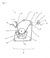
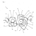
- the FIG. 1 shows a section of a first embodiment of a machine 1 according to the invention.
- the dewatering unit E is arranged in the pressing region of the machine 1.
- the pressing area is formed by a permeable pressing belt 5 and a suction roller 7.
- the fibrous web 2 is removed by means of the permeable support belt 3, which in this example is felt, by means of a suction roll from the surface of the preceding fabric, that is to say the forming fabric 6 and lying between the felt 3 and the permeable belt 4 through the press zone, guided.
- the fibrous web 2 is mechanically pressed due to the tension of the permeable press belt 5 and simultaneously flows through hot air.
- the hot air comes from the exhaust air of a drying unit of the paper machine, such as the hood exhaust air of a Glättzylinders and passes through the hood 9 via the fibrous web 2 in the suction zone 10 of the suction roller 7.
- a drying unit of the paper machine such as the hood exhaust air of a Glättzylinders
- the fibrous web 2 is traversed in the running direction over the entire length of the pressing zone of hot air.
- a steam blow pipe 8 is installed at the beginning of the press zone.
- the steam flows due to the pressure difference between the suction zone 10 and the hood 9 successively in addition by the permeable press belt 5, the permeable belt 4, the fibrous web 2 and through the felt in the suction zone 10 of the suction roller 7.
- the fibrous web 2 is heated and the Drainage favors.
- the permeable belt 4 is designed as felt or sieve. After passing through the press zone, the fibrous web 2 is passed through a downstream of the dewatering unit E press nip, which by the press roller 15 and the press roller 16 are formed.
- the pressure roller 15 lies in the loop of the permeable belt 4 and the pressure roller 16 is in the loop of the permeable support belt 3. This arrangement is characterized by the economy, since no additional clothing is required for the press nip.
- the fibrous web 2 is passed over a free train through another press nip. This is formed by a smoothing roll 11 and a press roll 12.
- the smoothing roll 11 is assigned to the upper side of the fibrous web 2. The top of the fibrous web 2 is thus smoothed.
- a coating application device which applies a pigment coating to the smoothed side of the fibrous web 2.
- This arrangement improves the surface quality of the fibrous web 2 in terms of further processing property, such as printability.
- the upper layer of the fibrous web the so-called ceiling layer.
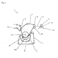
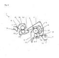
- the in the FIG. 2 illustrated embodiment is different from the FIG. 1 by the design of the downstream of the dewatering unit E press nip.
- the upper pressure roller 16 is again arranged in the loop of the support belt 3, while the lower pressure roller 15 is disposed outside the loop of the permeable belt 4 and is in direct contact with the underside of the fibrous web 2. This design also smoothes the bottom.
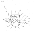
- the execution in the FIG. 3 shows a further variant of the dewatering unit E downstream press nip.
- the press nip is formed by a pressure roller 17 located in the loop of the permeable belt 4 and the suction roller 7 of the dewatering unit E.
- the suction roller 7 has in the region of the press nip to increase the dry content of the fibrous web 2, a further suction zone 10.1.
- This suction zone 10.1 is preferably evacuated independently of the suction zone 10.
- the press roll 17 is partially wrapped in common by the permeable band and the permeable support band. Thereafter, the permeable support belt 3 is separated from the fibrous web 2, which is guided on the permeable belt over a suction element 18.
- the press felt 13.1 takes the fibrous web 2 from the permeable belt 4 by means of a suction roll and guides them through a downstream smoothing nip formed by the press roll 12 and the smoothing roll 11.
- the smoothing roll 11 touches the bottom of the fibrous web 2 so that it is smoothed. This design has a convenient web guide for the horizontal continuation of the fibrous web.
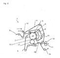
- the fibrous web 2 in contrast to the previous embodiments, removed by the permeable belt 4 by means of a suction roll from the surface of the preceding fabric 6 and passed through the press zone.
- FIG. 5 shows the mirrored drainage unit E of FIG. 3 ,
- the arrangements differ only in that the fibrous web 2 is removed by the permeable belt 4 by means of a suction roll from the surface of the preceding fabric 6 and passed through the press zone. In the subsequent smoothing gap, the underside of the fibrous web 2 is smoothed.
- the permeable belt 4 can be designed as felt or sieve.
- the permeable support band 3 is formed by a felt. The orderly press nip and smoothing gap is corresponding to the FIG. 3 described.
- the after-ordered press nip is a separate, ie stand-alone press nip, which is formed by the press rollers 15 and 16.
- FIGS. 7 and 8th shown arrangements of the dewatering unit E correspond to the arrangements of Figures 3 and 5 , The description therefore applies accordingly to the FIGS. 7 and 8th , The difference is that the drainage unit E is preceded by a separate, ie a stand-alone press nip, which is respectively formed by the press rolls 20 and 21.
- the lower press roller 21 is designed as a suction press roll.
- the fabrics 19 and 19.1 are formed as felts.
- the fibrous web 2 is in the case of FIG. 7 by the permeable support band 3, which is designed in this example as felt, and in the case of FIG. 8 through the permeable belt 4, which in this example is designed as a sieve, removed by means of a suction roller from the surface of the preceding clothing 19.1 and lying through the press zone between the felt 3 and the permeable belt 4, out.
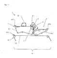
- the dewatering unit E is arranged in the forming area of the machine 1.
- the forming fabric 6 forms the permeable support band of the dewatering unit E.
- the permeable band can be embodied as a felt or as a sieve.
- the multilayer fibrous web 2 is removed directly from the forming fabric 6 by the felt of a subsequent machine section.
- the operation of the dewatering unit E is analogous to the previous descriptions.
- the dewatering unit is integrated into a layer forming area such that the forming fabric 6.1 forms the permeable band.
- the headbox 22 may be multi-layered, so that several fibrous web layers are formed on a Formiersieb 6.1.
- the thus formed fibrous web 2 can, as shown, be guided directly to the downstream smoothing nip, or be pored together with a fibrous web ply of another ply forming region and then guided to the downstream smoothing nip.
- the press roller 15.1 is designed as a shoe press roll.
- the press rollers 16 and 15.1 thus form an extended nip.
- the forming fabric 6.1 is designed as felt. This is particularly advantageous for lighter basis weights.
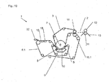
- the FIG. 11 shows a forming region IV with three Lagenformier Schemee I, II, III.
- the dewatering unit E is arranged in the layer forming region I, which forms the middle, ie an inner layer of the fibrous web 2.
- the operation of the drainage unit E is according to the description of the variant of FIG. 9 , However, the fibrous web layer formed is not transferred to a downstream machine section, but first with the on the Lagenformier Scheme II formed fibrous web layer and then sixteengegautscht with the formed on the Lagenformier Scheme III fibrous web layer.
- the Lagenformier Scheme I is formed from a fourdrinier screen 6.1 with attached Doppelsiebformêtieril 23 and a headbox 22.1.
- the Lagenformier Schemee II and III are designed as a long sieves 6.2 and 6.3 with the headboxes 22.2 and 22.3.
Landscapes
- Paper (AREA)
Abstract
Description
- Die Erfindung betrifft eine Maschine zur Herstellung einer mehrlagigen Faserstoffbahn, insbesondere einer Kartonbahn, mit einem, mindestens zwei Lagenformierbereiche zur Bildung der Faserstoffbahnlagen umfassenden Formierbereich zur Ausbildung der mehrlagigen Faserstoffbahn, sowie mit einem sich an den Formierbereich anschließenden Pressbereich. Die Erfindung betrifft auch ein Verfahren zur Herstellung einer mehrlagigen Faserstoffbahn, sowie die Verwendung der Maschine.
- Maschinen dieser Art sind bekannt. Das Dokument
EP1780332 A1 beschreibt eine Maschine zur Herstellung einer Kartonbahn. Dabei wird die Kartonbahn aus 4 Faserstoffbahnlagen, welche jeweils in Lagenformierbereichen gebildet werden, im Formierbereich hergestellt. Anschließend erfolgt die weitere Entwässerung durch Walzenpressen in einem Pressbereich. Die Trocknung erfolgt in einer darauffolgenden Trockenpartie. Zur Glättung einer Seite der Kartonbahn ist innerhalb der Trockenpartie ein Glättzylinder vorgesehen. Im Anschluss an die Trocknung ist ein Breitnipkalander zur weiteren Verbesserung der Glätte der Kartonbahn installiert. Danach folgt eine Streicheinrichtung zum Auftragen eines Strichs auf eine Seite der Kartonbahn mit anschließender Fertigtrocknung und Aufrollung der Kartonbahn. - Die Aufgabe der vorliegenden Erfindung liegt darin, den bekannten Herstellungsprozess für eine Papier- und Kartonbahn hinsichtlich deren Qualität und dessen Wirtschaftlichkeit zu verbessern.
- Die Aufgabe wird durch die Merkmale des Anspruches 1 gelöst. Erfindungswesentlich ist dabei, dass zur Entwässerung eine Entwässerungseinheit mit einer Presszone, durch die die Faserstoffbahn und/oder eine Faserstoffbahnlage zwischen einem umlaufenden, permeablen Band und einem umlaufenden, permeablen Stützband liegend, hindurchgeführt wird, vorgesehen ist und wobei die Presszone derart ausgebildet ist, dass das permeable Band, die Faserstoffbahn und/oder eine Faserstoffbahnlage und das permeable Stützband, zumindest auf einem Teil der Länge der Presszone, von einem Fluid durchströmt werden kann und die Presszone durch ein permeables Presselement und ein permeables Gegenelement gebildet ist.
- Durch den Einsatz der erfindungsgemäßen Entwässerungseinheit wird die Faserstoffbahn sanft entwässert, wobei der angewandte mechanische Entwässerungsdruck nahezu unabhängig von der Intensität der Durchströmung der Faserstoffbahn mit dem Fluid eingestellt werden kann. Dadurch werden die Festigkeitswerte der mehrlagigen Faserstoffbahn, insbesondere die Spaltfestigkeit, verbessert. Gleichzeitig erfolgt die Entwässerung sehr volumenschonend, sodass die Dicke der Faserstoffbahn durch den Pressvorgang weniger abnimmt als bei den bekannten Herstellungsprozessen. Da die Dicke der Faserstoffbahn die mechanische Beanspruchbarkeit, wie beispielsweise bei einer Biegebeanspruchung, wesentlich beeinflusst, kann durch die erfindungsgemäße Lösung die mechanische Beanspruchbarkeit der Faserstoffbahn gesteigert oder bei gleicher Beanspruchbarkeit Fasermaterial durch Reduzierung des Flächengewichts eingespart werden. Ebenso ermöglicht die erfindungsgemäße Lösung die Herstellung einer Papier- oder Kartonbahn, insbesondere einer Faltschachtelkartonbahn mit hohem spezifischem Volumen und gleichzeitig guter Glätte.
- Vorteilhafterweise wird die Durchströmrichtung des Fluids so gewählt, dass zuerst das permeable Presselement, danach das permeablen Band, die Faserstoffbahn beziehungsweise die Faserstoffbahnlage und anschließend das permeablen Stützband durchströmt werden.
- Das permeable Presselement ist vorzugsweise ein mechanisches Presselement zur Ausbildung eines mechanischen Druckes auf das permeable Band und somit auf die Faserstoffbahn.
- In praktischen Ausgestaltungsvarianten ist das Gegenelement als eine Walze oder einem Kasten mit gekrümmter oder ebener Kontaktfläche ausgeführt.
- Die Walze ist vorzugsweise eine Saugwalze. Vorteilhafterweise weist sie einen innen liegenden Saugkasten mit einer, vorzugsweise zwei oder mehr Saugzonen auf. Diese erstrecken sich im Wesentlichen, in Laufrichtung der Maschine gesehen, auf die Länge der Presszone.
- In weiteren Varianten kann die Saugwalze auch als gerillte oder als gerillte und gebohrte Walze ausgeführt sein. Für beide Varianten kann ein außen liegender Saugkasten zum Besaugen der Rillen vorgesehen sein. Dies ergibt eine effiziente Strömungsführung des Fluids durch die Presszone. Strömungsverluste können so minimiert werden.
- Zweckmäßigerweise besteht das permeable Presselement aus einem Pressband und/oder einem Pressschuh. Wird nur ein Pressband als Presselement verwendet, so ist es denkbar, innerhalb der Pressbandschlaufe ein weiteres Presselement, beispielsweise in Form einer Walze oder eines Pressschuhes, einzusetzen. So kann innerhalb der Presszone der mechanische Entwässerungsdruck lokal erhöht werden. Für den Fall dass der Pressschuh als Presselement dient, kann dieser permeabel oder gerillt und/oder gebohrt ausgeführt sein, um ein Durchströmen der Presszone mit dem Fluid zu ermöglichen.
- Ferner ist es von Vorteil, wenn das Pressband aus einem Siebgewebe, einem Spiralsieb, Metallsieb, perforiertem Metallband oder einem Band aus Verbundmaterial, wie beispielsweise aus Kohlefaser verstärktem Kunststoff, besteht.
- In einer praktischen Ausführung weist das Pressband eine Luftdurchlässigkeit von mehr als 100 cfm, insbesondere mehr als 200 cfm auf, wobei "cfm" das Luftvolumen in cubic feet angibt, das bei einem Differenzdruck von 125 Pa pro Fläche des Pressbandes in square foot und pro Minute durch das Pressband strömt. Das Messverfahren ist in der Norm TAPPI T251 beschrieben. Der Bereich der Luftdurchlässigkeit hat den Vorteil, dass bei einem gegebenen Differenzdruck zwischen der von der Faserstoffbahn abgewandten Seite des permeablen Stützbandes und der von dem permeablen Band abgewandten Seite des Pressbandes, ein möglichst hoher Volumenstrom des Fluids durch die Faserstoffbahn strömen kann. Ein weiterer Vorteil ist, dass dadurch der durch die Strömung erzeugte mechanische Druck klein bleibt.
- In einer weiteren Ausgestaltung der Erfindung ist das Pressband so gestaltet, dass eine Zugspannung von mehr als 30 kN/m, insbesondere von mehr als 40 kN/m, insbesondere von mehr als 45 kN/m im Betrieb der Maschine möglich ist.
- Die Entwässerungseinheit ist vorzugsweise so konfiguriert, dass der Pressdruck auf die Faserstoffbahn geringer als 0,9 bar insbesondere geringer als 0,5 bar, vorzugsweise geringer als 0,2 bar ist.
- Der Durchmesser des Gegenelements ist vorteilhafterweise größer als 1m, beziehungsweise der Krümmungsradius des Gegenelements ist größer als 0,5m.
- Für bestimmte Anwendungen kann das permeable Band eine strukturierte Oberfläche zur Strukturierung der Faserstoffbahn und/oder mindestens einer Faserstoffbahnlage aufweisen. Dies trifft insbesondere für Faserstoffbahnen zu, die nur einseitig glatt sein müssen oder für Faserstoffbahnlagen, welche eine innere Faserstoffbahnlage der mehrlagigen Faserstoffbahn bilden. Dies ermöglicht ein hohes spezifisches Volumen, ohne die Qualität der Faserstoffbahn hinsichtlich der erforderlichen Glätte zu beeinträchtigen.
- In einer weiteren Ausgestaltung der Erfindung wird das permeable Band durch ein Formiersieb gebildet. Formiersiebe sind dabei markierungsarm gestaltet. Dies wird durch bekannte Webarten erreicht. Die Webstruktur weist Stützpunkte in Bezug zur Faserstoffbahn auf. Vorzugsweise werden Webarten eingesetzt, welche mehr als 1300 Stützpunkte pro cm2, insbesondere mehr als 1400 Stützpunkte pro cm2, vorzugsweise mehr als 1500 Stützpunkte pro cm2 aufweisen. Dies hat den Vorteil, dass eine gute Glätte erreichbar ist.
- Es ist auch möglich, dass das permeable Band durch einen Filz gebildet ist.
- In einer Weiterentwicklung kann das permeable Band durch ein nicht gewobenes, permeables Band gebildet sein, welches zumindest auf der die Faserstoffbahn berührenden Seite beschichtet ist. Es ist auch denkbar, dass das permeable Band durch ein Kunststoffband, welches vorzugsweise eine innere Verstärkung aus einem Gewebeband oder einem Fadengelege aufweist, besteht.
- Das permeable Stützband ist vorzugsweise durch einen Filz gebildet. Dieser kann zumindest einen Teil des aus der Faserstoffbahn stammenden Wassers aufnehmen.
- In praktischen Anordnungen kann das permeable Stützband auch durch ein Formiersieb gebildet sein.
- In einer praktischen Ausführung ist die Entwässerungseinheit in mindestens einem Lagenformierbereich angeordnet.
- Zweckmäßigerweise sind in der Maschine drei oder mehr Lagenformierbereiche vorgesehen.
- Ferner ist es möglich, dass die Entwässerungseinheit in mindestens einem Lagenformierbereich für eine innere Lage angeordnet ist, wobei das Stützband durch ein Formiersieb des Lagenformierbereichs gebildet ist. Diese Variante bietet die Möglichkeit einen Karton mit einem hohen spezifischen Volumen zu erzeugen. Das permeable Band kann ein grobes, strukturiertes Sieb sein. Da die Faserstoffbahn in einer inneren Lage angeordnet ist und somit von einer äußeren Lage abgedeckt wird, ermöglicht diese Anordnung ebenfalls eine gute Glätte.
- Zur Verbesserung der Entwässerungsleistung der Entwässerungseinheit kann innerhalb der Schlaufe des Pressbandes oder des permeablen Bandes eine Haube vorgesehen sein. Der Haube wird das vorzugsweise heiße Fluid zugeführt. Vorteilhafterweise wird als heißes Fluid Luft und/oder Dampf eingesetzt. Die heiße Luft kann vorteilhafterweise aus der Abluft eines Trocknungsaggregates der Papiermaschine, wie beispielsweise der Haubenabluft eines Glättzylinders, stammen.
- Versuche haben gezeigt, dass durch die Entwässerungseinheit der Trockengehalt der Faserstoffbahn von beispielsweise 18% auf 40% gesteigert werden kann, während der Trockengehalt durch zwei Walzenpressen mit höherem Pressdruck auf lediglich 39% gesteigert werden konnte. Die Erfindung bringt neben der Steigerung der Qualität der Faserstoffbahn somit auch wirtschaftliche Vorteile.
- Innerhalb der Haube kann ein Dampfblasrohr, vorzugsweise am Beginn der Presszone vorgesehen sein.
- In einer weiteren Ausführungsform ist die Entwässerungseinheit im Pressbereich angeordnet.
- Ferner ist es möglich, dass die Entwässerungseinheit so angeordnet ist, dass die Faserstoffbahn von einer vorangehenden Oberfläche durch das permeable Band übernommen und durch die Presszone geführt wird.
- In einer weiteren Ausgestaltung ist es auch möglich, dass die Entwässerungseinheit so angeordnet ist, dass die Faserstoffbahn von einer vorangehenden Oberfläche durch das permeable Stützband übernommen und durch die Presszone geführt wird.
- Die vorangehende Oberfläche wird vorzugsweise durch ein Formiersieb eines Lagenformierbereichs gebildet.
- In einer praktischen Ausführungsform ist der Entwässerungseinheit ein Pressspalt vorgelagert.
- In einer weiteren praktischen Ausführungsform ist der Entwässerungseinheit ein, insbesondere doppelt befilzter, separat stehender Pressspalt vorgelagert.
- In einer vorteilhaften Weiterentwicklung ist der Presszone der Entwässerungseinheit mindestens ein Pressspalt nachgeordnet.
- Zweckmäßigerweise ist die Faserstoffbahn beim Durchlaufen des mindestens einen, der Presszone der Entwässerungseinheit nachgeordneten Pressspaltes, zwischen dem permeablen Stützband und dem permeablen Band angeordnet.
- Vorzugsweise ist der der Presszone der Entwässerungseinheit nachgeordnete Pressspalt durch eine separat stehende Walzenpresse gebildet. Es ist möglich, dass dabei die Faserstoffbahn zwischen dem permeablen Stützband und dem permeablen Band angeordnet ist.
- In einer praktischen Ausgestaltung ist der der Presszone der Entwässerungseinheit nach geordnete Pressspalt durch eine in der Schlaufe des permeablen Bandes angeordneten Presswalze und dem Gegenelement der Entwässerungseinheit gebildet. Das Gegenelement ist vorzugsweise als Saugwalze ausgebildet. Es ist möglich, dass dabei die Faserstoffbahn zwischen dem permeablen Stützband und dem permeablen Band angeordnet ist.
- In einer weiteren Ausgestaltung ist der nachgeordnete Pressspalt als Saugpresse ausgeführt, bei der eine Presswalze als eine Saugpresswalze ausgeführt ist.
- In einer weiteren möglichen Ausführung ist mindestens ein der Presszone der Entwässerungseinheit nachgeordneter Pressspalt durch eine Presswalze und eine Glättwalze gebildet und einfach befilzt, wobei eine Seite der Faserstoffbahn mit der glatten Oberfläche der Glättwalze in Kontakt ist.
- Es ist auch möglich, dass mindestens ein der Presszone der Entwässerungseinheit nachgeordneter Pressspalt durch zwei Glättwalzen gebildet ist, wobei beide Seiten der Faserstoffbahn mit der glatten Oberfläche der zugeordneten Glättwalze in Kontakt kommen.
- Vorteilhafterweise folgen nach dem Pressbereich Trocknungsvorrichtungen und eine Aufwickeleinheit. Zwischen den Trocknungsvorrichtungen und/oder nach den Trocknungsvorrichtungen ist mindestens ein Streichaggregat zum zumindest einseitigen Auftragen von Streichmedium auf die Faserstoffbahn vorgesehen. Das Streichmedium kann aus pigmentierter Streichfarbe, Stärke und/oder aus Leim bestehen.
- Vorzugsweise wird die Seite der Faserstoffbahn mit der höheren Glätte gestrichen.
- In einer praktischen Weiterentwicklung können zwei oder mehr Faserstoffbahnlagen in einem Lagenformierbereich gebildet sein. Hierfür wird ein Mehrschichtstoffauflauf eingesetzt, der mit unterschiedlichen Stoffsuspensionen gespeist wird. Diese werden bis zum Verlassen des Stoffauflaufes getrennt geführt und in einem Lagenformierbereich entwässert. Die Trennung erfolgt durch Lamellen in der Stoffauflaufdüse.
- Die Aufgabe wird auch durch ein Verfahren zur Herstellung einer mehrlagigen Faserstoffbahn, insbesondere einer Kartonbahn, in dem die Faserstoffbahn aus mindestens zwei Faserstoffbahnlagen gebildet wird, wobei die Faserstoffbahnlagen in einem Lagenformierbereiche umfassenden Formierbereich hergestellt werden und in einem sich an den Formierbereich anschließenden Pressbereich weiter entwässert wird, gelöst. Dabei ist erfindungswesentlich, dass im Formierbereich und/oder im Pressbereich eine Entwässerungseinheit nach Anspruch 1 verwendet wird, wobei in der Presszone die Faserstoffbahn und/oder mindestens eine Faserstoffbahnlage mechanisch gepresst und gleichzeitig von einem Fluid durchströmt wird.
- Die Maschine zur Herstellung von Karton findet vorzugsweise Verwendung für die Herstellung von Faltschachtelkarton.
- Die erfindungsgemäße Maschine ist besonders für die Herstellung von Faserstoffbahnen mit einem Flächengewicht von mehr als 40 g/m2, insbesondere von mehr als 60 g/m2 geeignet.
- Weitere Merkmale und Vorteile der Erfindung ergeben sich aus der nachfolgenden Beschreibung bevorzugter Ausführungsbeispiele unter Bezugnahme auf die Zeichnungen.
- Es zeigen
- Figur 1
- einen Ausschnitt einer ersten Ausführungsform einer erfindungsgemäßen Maschine, wobei die Entwässerungs-einheit im Pressbereich angeordnet ist.
- Figur 2
- einen Ausschnitt einer zweiten Ausführungsform einer erfindungsgemäßen Maschine, wobei die Entwässerungs-einheit im Pressbereich angeordnet ist.
- Figur 3
- einen Ausschnitt einer dritten Ausführungsform einer erfindungsgemäßen Maschine, wobei die Entwässerungs-einheit im Pressbereich angeordnet ist.
- Figur 4
- einen Ausschnitt einer vierten Ausführungsform einer erfindungsgemäßen Maschine, wobei die Entwässerungs-einheit im Pressbereich angeordnet ist.
- Figur 5
- einen Ausschnitt einer fünften Ausführungsform einer erfindungsgemäßen Maschine, wobei die Entwässerungs-einheit im Pressbereich angeordnet ist.
- Figur 6
- einen Ausschnitt einer sechsten Ausführungsform einer erfindungsgemäßen Maschine, wobei die Entwässerungs-einheit im Pressbereich angeordnet ist.
- Figur 7
- einen Ausschnitt einer siebten Ausführungsform einer erfindungsgemäßen Maschine, wobei die Entwässerungs-einheit im Pressbereich angeordnet ist.
- Figur 8
- einen Ausschnitt einer weiteren Ausführungsform einer erfindungsgemäßen Maschine, wobei die Entwässerungs-einheit im Pressbereich angeordnet ist.
- Figur 9
- einen Ausschnitt einer weiteren Ausführungsform einer erfindungsgemäßen Maschine, wobei die Entwässerungs-einheit im Formierbereich angeordnet ist.
- Figur 10
- einen Ausschnitt einer weiteren Ausführungsform einer erfindungsgemäßen Maschine, wobei die Entwässerungs-einheit im Formierbereich angeordnet ist.
- Figur 11
- einen Ausschnitt einer weiteren Ausführungsform einer erfindungsgemäßen Maschine, wobei die Entwässerungs-einheit im Formierbereich angeordnet ist.
- Die
Figur 1 zeigt einen Ausschnitt einer ersten Ausführungsform einer erfindungsgemäßen Maschine 1. Die Entwässerungseinheit E ist im Pressbereich der Maschine 1 angeordnet. Der Pressbereich ist durch ein permeables Pressband 5 und einer Saugwalze 7 gebildet. Die Faserstoffbahn 2 wird durch das permeable Stützband 3, welches in diesem Beispiel als Filz ausgeführt ist, mittels einer Saugwalze von der Oberfläche der vorausgehenden Bespannung, das heißt des Formiersiebes 6 abgenommen und durch die Presszone zwischen dem Filz 3 und dem permeablen Band 4 liegend, geführt. In der Presszone wird die Faserstoffbahn 2 infolge der Spannung des permeablen Pressbandes 5 mechanisch gepresst und gleichzeitig von heißer Luft durchströmt. Die heiße Luft stammt aus der Abluft eines Trocknungsaggregates der Papiermaschine, wie beispielsweise der Haubenabluft eines Glättzylinders und gelangt über die Haube 9 über die Faserstoffbahn 2 in die Saugzone 10 der Saugwalze 7. Dadurch werden Wärmeverluste im Herstellungsprozess reduziert. In diesem Beispiel wird die Faserstoffbahn 2 in Laufrichtung auf der gesamten Länge der Presszone von heißer Luft durchströmt. Am Beginn der Presszone ist ein Dampfblasrohr 8 installiert. Der Dampf strömt infolge der Druckdifferenz zwischen der Saugzone 10 und der Haube 9 nacheinander zusätzlich durch das permeable Pressband 5, das permeable Band 4, die Faserstoffbahn 2 und durch den Filz in die Saugzone 10 der Saugwalze 7. Dadurch wird die Faserstoffbahn 2 erwärmt und die Entwässerung begünstigt. Das permeable Band 4 ist als Filz oder Sieb ausgeführt. Nach Durchlaufen der Presszone wird die Faserstoffbahn 2 durch einen der Entwässerungseinheit E nachgeordneten Pressspalt geführt, welcher durch die Presswalze 15 und die Presswalze 16 gebildet ist. Die Presswalze 15 liegt dabei in der Schlaufe des permeablen Bandes 4 und die Presswalze 16 liegt in der Schlaufe des permeablen Stützbandes 3. Diese Anordnung zeichnet sich durch die Wirtschaftlichkeit aus, da für den Pressspalt keine zusätzlichen Bespannungen benötigt werden. Anschließend wird die Faserstoffbahn 2 über einen freien Zug durch einen weiteren Pressspalt geführt. Dieser wird durch eine Glättwalze 11 und einer Presswalze 12 gebildet. Die Glättwalze 11 ist der Oberseite der Faserstoffbahn 2 zugeordnet. Die Oberseite der Faserstoffbahn 2 wird somit geglättet. Im weiteren Verlauf des Herstellungsprozesses folgt eine Streichauftragseinrichtung, welche auf die geglättete Seite der Faserstoffbahn 2 einen Pigmentstrich aufträgt. Diese Anordnung verbessert die Oberflächenqualität der Faserstoffbahn 2 hinsichtlich der weiteren Verarbeitungseigenschaft, wie beispielsweise Bedruckbarkeit. Bei der Produktion von Faltschachtelkarton bildet bei dieser Anordnung die obere Lage der Faserstoffbahn die sogenannte Deckenlage. - Die in der
Figur 2 dargestellte Ausführung unterscheidet sich von derFigur 1 durch die Gestaltung des der Entwässerungseinheit E nachgeordneten Pressspaltes. Die obere Presswalze 16 ist wiederum in der Schlaufe des Stützbandes 3 angeordnet, während die untere Presswalze 15 außerhalb der Schlaufe des permeablen Bandes 4 angeordnet ist und in direktem Kontakt mit der Unterseite der Faserstoffbahn 2 steht. Diese Ausführung glättet auch die Unterseite. - Die Ausführung in der
Figur 3 zeigt eine weitere Variante des der Entwässerungseinheit E nachgeordneten Pressspaltes. Der Pressspalt wird durch eine in der Schlaufe des permeablen Bandes 4 liegenden Presswalze 17 und der Saugwalze 7 der Entwässerungseinheit E gebildet. Die Saugwalze 7 weist im Bereich des Pressspaltes zur Steigerung des Trockengehaltes der Faserstoffbahn 2 eine weitere Saugzone 10.1 auf. Diese Saugzone 10.1 ist vorzugsweise unabhängig von der Saugzone 10 besaugt. Die Presswalze 17 wird vom permeablen Band und vom permeablen Stützband teilweise gemeinsam umschlungen. Danach wird das permeable Stützband 3 von der Faserstoffbahn 2 getrennt, welche auf dem permeablen Band liegend über ein Saugelement 18 geführt wird. Der Pressfilz 13.1 nimmt die Faserstoffbahn 2 vom permeablen Band 4 mittels einer Saugwalze ab und führt sie durch einen nachgeordneten Glättspalt, der durch die Presswalze 12 und der Glättwalze 11 gebildet wird. Dabei berührt die Glättwalze 11 die Unterseite der Faserstoffbahn 2 so, dass sie geglättet wird. Diese Ausführung weist eine günstige Bahnführung zur horizontalen Weiterführung der Faserstoffbahn auf. - In der Anordnung der
Figur 4 wird die Faserstoffbahn 2, im Gegensatz zu den bisherigen Ausführungsvarianten, durch das permeable Band 4 mittels einer Saugwalze von der Oberfläche der vorausgehenden Bespannung 6 abgenommen und durch die Presszone geführt. - Die
Figur 5 zeigt die gespiegelte Entwässerungseinheit E derFigur 3 . Die Anordnungen unterscheiden sich lediglich dadurch, dass die Faserstoffbahn 2 durch das permeable Band 4 mittels einer Saugwalze von der Oberfläche der vorausgehenden Bespannung 6 abgenommen und durch die Presszone geführt wird. In dem nachfolgenden Glättspalt wird die Unterseite der Faserstoffbahn 2 geglättet. Das permeable Band 4 kann als Filz oder Sieb ausgeführt sein. Das permeable Stützband 3 wird durch einen Filz gebildet. Der nach geordnete Pressspalt und Glättspalt ist entsprechend bei derFigur 3 beschrieben. - In der Variante der
Figur 6 unterscheidet sich von der in derFigur 5 beschriebenen Anordnung dadurch, dass der nach geordnete Pressspalt ein separater, d.h. einzeln stehender Pressspalt ist, der durch die Presswalzen 15 und 16 gebildet ist. - Die in den
Figuren 7 und8 dargestellten Anordnungen der Entwässerungseinheit E entsprechen den Anordnungen derFiguren 3 und5 . Die Beschreibung gilt daher entsprechend für dieFiguren 7 und8 . Der Unterschied besteht darin, dass der Entwässerungseinheit E ein separater, d.h. ein einzeln stehender Pressspalt, der jeweils durch die Presswalzen 20 und 21 gebildet wird, vorgeschaltet ist. Dabei ist jeweils die untere Presswalze 21 als Saugpresswalze ausgeführt. Die Bespannungen 19 und 19.1 sind als Filze ausgebildet. Durch diese Anordnungen können große Wassermengen entwässert werden. Die Faserstoffbahn 2 wird im Falle derFigur 7 durch das permeable Stützband 3, welches in diesem Beispiel als Filz ausgeführt ist, und im Falle derFigur 8 durch das permeable Band 4, welches in diesem Beispiel als Sieb ausgeführt ist, mittels einer Saugwalze von der Oberfläche der vorausgehenden Bespannung 19.1 abgenommen und durch die Presszone zwischen dem Filz 3 und dem permeablen Band 4 liegend, geführt. - In den folgenden
Figuren 9 ,10 ,11 ist die Entwässerungseinheit E im Formierbereich der Maschine 1 angeordnet. In der Anordnung derFigur 9 bildet das Formiersieb 6 das permeable Stützband der Entwässerungseinheit E. Das permeable Band kann bei dieser Variante als Filz oder als Sieb ausgeführt sein. Die mehrlagige Faserstoffbahn 2 wird direkt durch den Filz einer nachfolgenden Maschinensektion vom Formiersieb 6 abgenommen. Die Funktionsweise der Entwässerungseinheit E ist analog den vorangegangenen Beschreibungen. - Die in der
Figur 10 dargestellten Variante ist die Entwässerungseinheit in einen Lagenformierbereich so integriert, dass das Formiersieb 6.1 das permeable Band bildet. Der Stoffauflauf 22 kann mehrschichtig ausgeführt sein, sodass mehrere Faserstoffbahnlagen auf einem Formiersieb 6.1 gebildet werden. Die so gebildete Faserstoffbahn 2 kann, wie dargestellt direkt zum nachgeordenten Glättspalt geführt werden, oder mit einer Faserstoffbahnlage eines anderen Lagenformierbereichs zusammengegautscht werden und danach zum nachgeordenten Glättspalt geführt werden. Die Presswalze 15.1 ist als Schuhpresswalze ausgeführt. Die Presswalzen 16 und 15.1 bilden somit einen Langspalt aus. In einer speziellen Ausgestaltung ist das Formiersieb 6.1 als Filz ausgeführt. Dies ist besonders für leichtere Flächengewichte von Vorteil. - Die
Figur 11 zeigt einen Formierbereich IV mit drei Lagenformierbereiche I, II, III. Die Entwässerungseinheit E ist im Lagenformierbereich I angeordnet, der die mittlere, d.h. eine innere Lage der Faserstoffbahn 2 bildet. Die Funktionsweise der Entwässerungseinheit E ist entsprechend der Beschreibung der Variante derFigur 9 . Allerdings wird die gebildete Faserstoffbahnlage nicht an eine nachgeordnete Maschinensektion übergeben, sondern zuerst mit der auf dem Lagenformierbereich II gebildeten Faserstoffbahnlage und anschließend mit der auf dem Lagenformierbereich III gebildeten Faserstoffbahnlage zusammengegautscht. Der Lagenformierbereich I wird aus einem Langsieb 6.1 mit aufgesetztem Doppelsiebformierteil 23 und einem Stoffauflauf 22.1 gebildet. Die Lagenformierbereiche II und III sind als Langsiebe 6.2 und 6.3 mit den Stoffaufläufen 22.2 und 22.3 ausgeführt. - Die allgemeinen Beschreibungen der Funktionsweise der Entwässerungseinheit E und der sich wiederholenden Elemente für die unterschiedlichen Ausführungen sind zwischen den entsprechenden Ausführungen übertragbar.
-
- 1
- Maschine
- 2
- Faserstoffbahn
- 3
- permeables Stützband
- 4
- permeables Band
- 4.1
- permeables Band
- 5
- Presselement, Pressband
- 6
- Formiersieb
- 6.1
- Formiersieb einer Faserstoffbahnlage
- 6.2
- Formiersieb einer Faserstoffbahnlage
- 6.3
- Formiersieb einer Faserstoffbahnlage
- 7
- Gegenelement, Saugwalze
- 8
- Dampfblasrohr
- 9
- Haube
- 10
- Saugzone
- 10.1
- Saugzone
- 11
- Glättwalze
- 12
- Presswalze
- 13
- Pressfilz, Band
- 13.1
- Pressfilz, Band
- 14
- pick up-Stelle
- 14.1
- pick up-Stelle
- 15
- Presswalze
- 15.1
- Schuhpresswalze
- 16
- Presswalze
- 17
- Presswalze
- 18
- Saugelement
- 19
- Pressfilz
- 19.1
- Pressfilz
- 20
- Presswalze
- 21
- Presswalze
- 22
- Stoffauflauf
- 22.1
- Stoffauflauf
- 22.2
- Stoffauflauf
- 22.3
- Stoffauflauf
- 23
- Doppelsiebformierteil
- I
- Lagenformierbereich
- II
- Lagenformierbereich
- III
- Lagenformierbereich
- IV
- Formierbereich
- E
- Entwässerungseinheit
Claims (12)
- Maschine (1) zur Herstellung einer mehrlagigen Faserstoffbahn (2), insbesondere einer Kartonbahn, mit einem, mindestens zwei Lagenformierbereiche (I, II, III) zur Bildung der Faserstoffbahnlagen umfassenden Formierbereich (IV) zur Ausbildung der mehrlagigen Faserstoffbahn (2), sowie mit einem sich an den Formierbereich (IV) anschließenden Pressbereich,
dadurch gekennzeichnet,
dass zur Entwässerung eine Entwässerungseinheit (E) mit einer Presszone, durch die eine Faserstoffbahnlage zwischen einem umlaufenden, permeablen Band (4, 4.1, 6.1) und einem umlaufenden, permeablen Stützband (3, 6, 6.1) liegend, hindurchgeführt wird, vorgesehen ist und wobei die Presszone derart ausgebildet ist, dass das permeable Band (4, 4.1, 6.1), eine Faserstoffbahnlage und das permeable Stützband (3, 6, 6.1), zumindest auf einem Teil der Länge der Presszone, von einem Fluid durchströmt werden kann und die Presszone durch ein permeables Presselement (5) und ein permeables Gegenelement (7) gebildet ist. - Maschine nach Anspruch 1,
dadurch gekennzeichnet,
dass das Gegenelement (7) aus einer Walze oder einem Kasten mit gekrümmter oder ebener Kontaktfläche besteht. - Maschine nach Anspruch 1 oder 2,
dadurch gekennzeichnet,
dass das permeable Presselement (5) aus einem Pressband und/oder einem Pressschuh besteht. - Maschine nach Anspruch 3,
dadurch gekennzeichnet,
dass das Pressband (5) aus einem Siebgewebe, Spiralsieb, Metallsieb,
perforiertem Metallband oder einem Band aus Verbundmaterial besteht. - Maschine nach einem der vorhergehenden Ansprüche,
dadurch gekennzeichnet,
dass das permeable Band (4, 4.1, 6.1) eine strukturierte Oberfläche zur Strukturierung mindestens einer Faserstoffbahnlage aufweist. - Maschine nach einem der vorhergehenden Ansprüche,
dadurch gekennzeichnet,
dass das permeable Band durch ein Formiersieb (6.1) gebildet ist. - Maschine nach einem der vorhergehenden Ansprüche,
dadurch gekennzeichnet,
dass die Entwässerungseinheit (E) in mindestens einem Lagenformierbereich (I, II, III) angeordnet ist. - Maschine nach einem der vorhergehenden Ansprüche,
dadurch gekennzeichnet,
dass drei oder mehr Lagenformierbereiche (I, II, III) vorgesehen sind. - Maschine nach Anspruch 8
dadurch gekennzeichnet,
dass die Entwässerungseinheit (E) in mindestens einem Lagenformierbereich (II) für eine innere Lage angeordnet ist, wobei das Stützband durch ein Formiersieb (6, 6.1) des Lagenformierbereichs (II) gebildet ist. - Maschine nach einem der vorhergehenden Ansprüche,
dadurch gekennzeichnet,
dass nach dem Pressbereich Trocknungsvorrichtungen folgen und dass zwischen den Trocknungsvorrichtungen und/oder nach den Trocknungsvorrichtungen mindestens ein Streichaggregat zum zumindest einseitigen Auftragen von Streichmedium auf die Faserstoffbahn (2) vorgesehen ist. - Verfahren zur Herstellung einer mehrlagigen Faserstoffbahn (2), insbesondere einer Kartonbahn, in dem die Faserstoffbahn (2) aus mindestens zwei Faserstoffbahnlagen gebildet wird, wobei die Faserstoffbahnlagen in einem Lagenformierbereiche (I, II, III) umfassenden Formierbereich (IV) hergestellt werden und in einem sich an den Formierbereich (IV) anschließenden Pressbereich weiter entwässert wird,
dadurch gekennzeichnet,
dass im Formierbereich (IV) und/oder im Pressbereich eine Entwässerungseinheit (E) nach Anspruch 1 verwendet wird, wobei in der Presszone mindestens eine Faserstoffbahnlage mechanisch gepresst und gleichzeitig von einem Fluid durchströmt wird. - Verwendung der Maschine 1 nach Anspruch 1 zur Herstellung von Karton, insbesondere von Faltschachtelkarton.
Applications Claiming Priority (2)
| Application Number | Priority Date | Filing Date | Title |
|---|---|---|---|
| DE201010044079 DE102010044079A1 (de) | 2010-11-17 | 2010-11-17 | Vorrichtung und Verfahren zur Herstellung einer Materialbahn |
| EP11773254.5A EP2640890B1 (de) | 2010-11-17 | 2011-10-21 | Vorrichtung und verfahren zur herstellung einer materialbahn |
Related Parent Applications (2)
| Application Number | Title | Priority Date | Filing Date |
|---|---|---|---|
| EP11773254.5A Division-Into EP2640890B1 (de) | 2010-11-17 | 2011-10-21 | Vorrichtung und verfahren zur herstellung einer materialbahn |
| EP11773254.5A Division EP2640890B1 (de) | 2010-11-17 | 2011-10-21 | Vorrichtung und verfahren zur herstellung einer materialbahn |
Publications (2)
| Publication Number | Publication Date |
|---|---|
| EP2712958A1 true EP2712958A1 (de) | 2014-04-02 |
| EP2712958B1 EP2712958B1 (de) | 2016-04-13 |
Family
ID=44862995
Family Applications (2)
| Application Number | Title | Priority Date | Filing Date |
|---|---|---|---|
| EP13198087.2A Not-in-force EP2712958B1 (de) | 2010-11-17 | 2011-10-21 | Vorrichtung und Verfahren zur Herstellung einer Materialbahn |
| EP11773254.5A Not-in-force EP2640890B1 (de) | 2010-11-17 | 2011-10-21 | Vorrichtung und verfahren zur herstellung einer materialbahn |
Family Applications After (1)
| Application Number | Title | Priority Date | Filing Date |
|---|---|---|---|
| EP11773254.5A Not-in-force EP2640890B1 (de) | 2010-11-17 | 2011-10-21 | Vorrichtung und verfahren zur herstellung einer materialbahn |
Country Status (4)
| Country | Link |
|---|---|
| EP (2) | EP2712958B1 (de) |
| CN (1) | CN103328723A (de) |
| DE (1) | DE102010044079A1 (de) |
| WO (1) | WO2012065804A1 (de) |
Families Citing this family (5)
| Publication number | Priority date | Publication date | Assignee | Title |
|---|---|---|---|---|
| WO2015000690A1 (de) * | 2013-07-04 | 2015-01-08 | Voith Patent Gmbh | Verfahren und kompakte vorrichtung zur herstellung von vliesstoff |
| WO2015000687A1 (de) * | 2013-07-04 | 2015-01-08 | Voith Patent Gmbh | Verfahren zum umrüsten und betreiben einer vorrichtung zum herstellen von vliesstoff |
| WO2016066375A1 (de) * | 2014-10-29 | 2016-05-06 | Voith Patent Gmbh | Vorrichtung zur entwässerung einer faserstoffbahn |
| CN105735026B (zh) * | 2014-12-11 | 2019-08-09 | 福伊特专利有限公司 | 用于制造纤维材料腹板的机器 |
| DE102022133436A1 (de) * | 2022-12-15 | 2024-06-20 | Voith Patent Gmbh | Vorrichtung zur Herstellung einer Faserstoffbahn und entsprechendes Herstellungsverfahren |
Citations (5)
| Publication number | Priority date | Publication date | Assignee | Title |
|---|---|---|---|---|
| EP1780332A1 (de) | 2005-10-28 | 2007-05-02 | Voith Patent GmbH | Vorrichtung und Verfahren zum Behandeln einer Faserstoffbahn, insbesondere einer Karton- oder Papierbahn |
| EP2085515A2 (de) * | 2008-02-04 | 2009-08-05 | Voith Patent GmbH | Vorrichtung zur Entwässerung von Tissuebahnen |
| DE102009027143A1 (de) * | 2008-06-27 | 2009-12-31 | Metso Paper, Inc. | Vorpresse, Formierpartie und Anlage zur Herstellung einer mehrlagigen Materialbahn |
| DE102008054990A1 (de) * | 2008-12-19 | 2010-06-24 | Voith Patent Gmbh | Vorrichtung und Verfahren zur Herstellung einer Materialbahn |
| WO2011151201A1 (de) * | 2010-06-01 | 2011-12-08 | Voith Patent Gmbh | Nasspartie einer maschine zur herstellung von faserstoffbahnen und verwendung einer derartigen nasspartie |
Family Cites Families (3)
| Publication number | Priority date | Publication date | Assignee | Title |
|---|---|---|---|---|
| US4879001A (en) * | 1988-09-12 | 1989-11-07 | Beloit Corporation | Twin wire former with roll press followed by extended nip press |
| US7416637B2 (en) * | 2004-07-01 | 2008-08-26 | Georgia-Pacific Consumer Products Lp | Low compaction, pneumatic dewatering process for producing absorbent sheet |
| US20100193149A1 (en) * | 2008-07-03 | 2010-08-05 | Quigley Scott D | Structured forming fabric, papermaking machine and method |
-
2010
- 2010-11-17 DE DE201010044079 patent/DE102010044079A1/de not_active Withdrawn
-
2011
- 2011-10-21 EP EP13198087.2A patent/EP2712958B1/de not_active Not-in-force
- 2011-10-21 CN CN2011800652419A patent/CN103328723A/zh active Pending
- 2011-10-21 EP EP11773254.5A patent/EP2640890B1/de not_active Not-in-force
- 2011-10-21 WO PCT/EP2011/068403 patent/WO2012065804A1/de not_active Ceased
Patent Citations (5)
| Publication number | Priority date | Publication date | Assignee | Title |
|---|---|---|---|---|
| EP1780332A1 (de) | 2005-10-28 | 2007-05-02 | Voith Patent GmbH | Vorrichtung und Verfahren zum Behandeln einer Faserstoffbahn, insbesondere einer Karton- oder Papierbahn |
| EP2085515A2 (de) * | 2008-02-04 | 2009-08-05 | Voith Patent GmbH | Vorrichtung zur Entwässerung von Tissuebahnen |
| DE102009027143A1 (de) * | 2008-06-27 | 2009-12-31 | Metso Paper, Inc. | Vorpresse, Formierpartie und Anlage zur Herstellung einer mehrlagigen Materialbahn |
| DE102008054990A1 (de) * | 2008-12-19 | 2010-06-24 | Voith Patent Gmbh | Vorrichtung und Verfahren zur Herstellung einer Materialbahn |
| WO2011151201A1 (de) * | 2010-06-01 | 2011-12-08 | Voith Patent Gmbh | Nasspartie einer maschine zur herstellung von faserstoffbahnen und verwendung einer derartigen nasspartie |
Also Published As
| Publication number | Publication date |
|---|---|
| DE102010044079A1 (de) | 2012-05-24 |
| EP2640890B1 (de) | 2015-09-23 |
| EP2640890A1 (de) | 2013-09-25 |
| EP2712958B1 (de) | 2016-04-13 |
| WO2012065804A1 (de) | 2012-05-24 |
| CN103328723A (zh) | 2013-09-25 |
Similar Documents
| Publication | Publication Date | Title |
|---|---|---|
| EP2699728B1 (de) | Vorrichtung und verfahren zur herstellung einer materialbahn | |
| EP1397587B1 (de) | Verfahren und vorrichtung zur herstellung einer mit einer dreidimensionalen oberflächenstruktur versehen faserstoffbahn | |
| EP1749934B1 (de) | Maschine zur Herstellung von Tissuepapier | |
| DE102008054990A1 (de) | Vorrichtung und Verfahren zur Herstellung einer Materialbahn | |
| DE102006062235A1 (de) | Verfahren und Vorrichtung zur Trocknung einer Faserstoffbahn | |
| WO2008077869A1 (de) | Verfahren und vorrichtung zur trocknung einer faserstoffbahn | |
| EP3835482B1 (de) | Maschine und verfahren zur herstellung einer faserstoffbahn | |
| EP2640890B1 (de) | Vorrichtung und verfahren zur herstellung einer materialbahn | |
| DE102016204969A1 (de) | Vorrichtung und Verfahren zur Herstellung einer Faserstoffbahn in einer Papiermaschine | |
| AT511561B1 (de) | Verfahren und Fertigungslinie zur Herstellung einer mehrschichtigen Materialbahn | |
| EP3152360B1 (de) | Einrichtung zum herstellen einer faserstoffbahn | |
| DE102010031440A1 (de) | Verfahren und Maschine zur Herstellung einer Faserstoffbahn | |
| DE102011077523A1 (de) | Maschine zur Herstellung einer einseitig-glatten Faserstoffbahn | |
| DE10159115A1 (de) | Pressenpartie | |
| DE102010031450A1 (de) | Verfahren und Maschine zur Herstellung einer Faserstoffbahn | |
| EP0863254B1 (de) | Verfahren und Papiermaschine zur Herstellung einer mehrlagigen Faserstoffbahn | |
| DE202017106978U1 (de) | Siebpartie, insbesondere eine umgebaute Siebpartie | |
| DE102010031320A1 (de) | Maschine mit einer Pressenpartie und Verfahren zur Herstellung einer Faserstoffbahn | |
| WO2017092931A1 (de) | Vorrichtung zur herstellung einer faserstoffbahn | |
| EP2235256A1 (de) | Vorrichtung zur herstellung und/oder behandlung einer faserstoffbahn | |
| EP3384083B1 (de) | Vorrichtung zur herstellung einer faserstoffbahn | |
| DE102010029582A1 (de) | Nasspartie einer Maschine zur Herstellung von Faserstoffbahnen und Verwendung einer derartigen Nasspartie | |
| DE102016218101A1 (de) | Vorrichtung und Verfahren zur Herstellung einer Faserstoffbahn in einer Papiermaschine | |
| DE102009045185A1 (de) | Maschine zur Herstellung einer Faserstoffbahn | |
| DE102010031447A1 (de) | Verfahren und Maschine zur Herstellung einer Faserstoffbahn |
Legal Events
| Date | Code | Title | Description |
|---|---|---|---|
| PUAI | Public reference made under article 153(3) epc to a published international application that has entered the european phase |
Free format text: ORIGINAL CODE: 0009012 |
|
| AC | Divisional application: reference to earlier application |
Ref document number: 2640890 Country of ref document: EP Kind code of ref document: P |
|
| AK | Designated contracting states |
Kind code of ref document: A1 Designated state(s): AL AT BE BG CH CY CZ DE DK EE ES FI FR GB GR HR HU IE IS IT LI LT LU LV MC MK MT NL NO PL PT RO RS SE SI SK SM TR |
|
| 17P | Request for examination filed |
Effective date: 20141002 |
|
| RBV | Designated contracting states (corrected) |
Designated state(s): AL AT BE BG CH CY CZ DE DK EE ES FI FR GB GR HR HU IE IS IT LI LT LU LV MC MK MT NL NO PL PT RO RS SE SI SK SM TR |
|
| GRAP | Despatch of communication of intention to grant a patent |
Free format text: ORIGINAL CODE: EPIDOSNIGR1 |
|
| INTG | Intention to grant announced |
Effective date: 20160108 |
|
| GRAS | Grant fee paid |
Free format text: ORIGINAL CODE: EPIDOSNIGR3 |
|
| GRAA | (expected) grant |
Free format text: ORIGINAL CODE: 0009210 |
|
| AC | Divisional application: reference to earlier application |
Ref document number: 2640890 Country of ref document: EP Kind code of ref document: P |
|
| AK | Designated contracting states |
Kind code of ref document: B1 Designated state(s): AL AT BE BG CH CY CZ DE DK EE ES FI FR GB GR HR HU IE IS IT LI LT LU LV MC MK MT NL NO PL PT RO RS SE SI SK SM TR |
|
| REG | Reference to a national code |
Ref country code: GB Ref legal event code: FG4D Free format text: NOT ENGLISH |
|
| REG | Reference to a national code |
Ref country code: AT Ref legal event code: REF Ref document number: 790305 Country of ref document: AT Kind code of ref document: T Effective date: 20160415 Ref country code: CH Ref legal event code: EP |
|
| REG | Reference to a national code |
Ref country code: IE Ref legal event code: FG4D Free format text: LANGUAGE OF EP DOCUMENT: GERMAN |
|
| REG | Reference to a national code |
Ref country code: DE Ref legal event code: R096 Ref document number: 502011009456 Country of ref document: DE |
|
| REG | Reference to a national code |
Ref country code: LT Ref legal event code: MG4D |
|
| REG | Reference to a national code |
Ref country code: NL Ref legal event code: MP Effective date: 20160413 |
|
| PG25 | Lapsed in a contracting state [announced via postgrant information from national office to epo] |
Ref country code: LT Free format text: LAPSE BECAUSE OF FAILURE TO SUBMIT A TRANSLATION OF THE DESCRIPTION OR TO PAY THE FEE WITHIN THE PRESCRIBED TIME-LIMIT Effective date: 20160413 Ref country code: NO Free format text: LAPSE BECAUSE OF FAILURE TO SUBMIT A TRANSLATION OF THE DESCRIPTION OR TO PAY THE FEE WITHIN THE PRESCRIBED TIME-LIMIT Effective date: 20160713 Ref country code: NL Free format text: LAPSE BECAUSE OF FAILURE TO SUBMIT A TRANSLATION OF THE DESCRIPTION OR TO PAY THE FEE WITHIN THE PRESCRIBED TIME-LIMIT Effective date: 20160413 Ref country code: FI Free format text: LAPSE BECAUSE OF FAILURE TO SUBMIT A TRANSLATION OF THE DESCRIPTION OR TO PAY THE FEE WITHIN THE PRESCRIBED TIME-LIMIT Effective date: 20160413 Ref country code: PL Free format text: LAPSE BECAUSE OF FAILURE TO SUBMIT A TRANSLATION OF THE DESCRIPTION OR TO PAY THE FEE WITHIN THE PRESCRIBED TIME-LIMIT Effective date: 20160413 |
|
| PG25 | Lapsed in a contracting state [announced via postgrant information from national office to epo] |
Ref country code: GR Free format text: LAPSE BECAUSE OF FAILURE TO SUBMIT A TRANSLATION OF THE DESCRIPTION OR TO PAY THE FEE WITHIN THE PRESCRIBED TIME-LIMIT Effective date: 20160714 Ref country code: PT Free format text: LAPSE BECAUSE OF FAILURE TO SUBMIT A TRANSLATION OF THE DESCRIPTION OR TO PAY THE FEE WITHIN THE PRESCRIBED TIME-LIMIT Effective date: 20160816 Ref country code: LV Free format text: LAPSE BECAUSE OF FAILURE TO SUBMIT A TRANSLATION OF THE DESCRIPTION OR TO PAY THE FEE WITHIN THE PRESCRIBED TIME-LIMIT Effective date: 20160413 Ref country code: SE Free format text: LAPSE BECAUSE OF FAILURE TO SUBMIT A TRANSLATION OF THE DESCRIPTION OR TO PAY THE FEE WITHIN THE PRESCRIBED TIME-LIMIT Effective date: 20160413 Ref country code: HR Free format text: LAPSE BECAUSE OF FAILURE TO SUBMIT A TRANSLATION OF THE DESCRIPTION OR TO PAY THE FEE WITHIN THE PRESCRIBED TIME-LIMIT Effective date: 20160413 Ref country code: ES Free format text: LAPSE BECAUSE OF FAILURE TO SUBMIT A TRANSLATION OF THE DESCRIPTION OR TO PAY THE FEE WITHIN THE PRESCRIBED TIME-LIMIT Effective date: 20160413 Ref country code: RS Free format text: LAPSE BECAUSE OF FAILURE TO SUBMIT A TRANSLATION OF THE DESCRIPTION OR TO PAY THE FEE WITHIN THE PRESCRIBED TIME-LIMIT Effective date: 20160413 |
|
| PG25 | Lapsed in a contracting state [announced via postgrant information from national office to epo] |
Ref country code: IT Free format text: LAPSE BECAUSE OF FAILURE TO SUBMIT A TRANSLATION OF THE DESCRIPTION OR TO PAY THE FEE WITHIN THE PRESCRIBED TIME-LIMIT Effective date: 20160413 |
|
| REG | Reference to a national code |
Ref country code: DE Ref legal event code: R097 Ref document number: 502011009456 Country of ref document: DE |
|
| PG25 | Lapsed in a contracting state [announced via postgrant information from national office to epo] |
Ref country code: DK Free format text: LAPSE BECAUSE OF FAILURE TO SUBMIT A TRANSLATION OF THE DESCRIPTION OR TO PAY THE FEE WITHIN THE PRESCRIBED TIME-LIMIT Effective date: 20160413 Ref country code: RO Free format text: LAPSE BECAUSE OF FAILURE TO SUBMIT A TRANSLATION OF THE DESCRIPTION OR TO PAY THE FEE WITHIN THE PRESCRIBED TIME-LIMIT Effective date: 20160413 Ref country code: EE Free format text: LAPSE BECAUSE OF FAILURE TO SUBMIT A TRANSLATION OF THE DESCRIPTION OR TO PAY THE FEE WITHIN THE PRESCRIBED TIME-LIMIT Effective date: 20160413 Ref country code: SK Free format text: LAPSE BECAUSE OF FAILURE TO SUBMIT A TRANSLATION OF THE DESCRIPTION OR TO PAY THE FEE WITHIN THE PRESCRIBED TIME-LIMIT Effective date: 20160413 Ref country code: CZ Free format text: LAPSE BECAUSE OF FAILURE TO SUBMIT A TRANSLATION OF THE DESCRIPTION OR TO PAY THE FEE WITHIN THE PRESCRIBED TIME-LIMIT Effective date: 20160413 |
|
| PLBE | No opposition filed within time limit |
Free format text: ORIGINAL CODE: 0009261 |
|
| STAA | Information on the status of an ep patent application or granted ep patent |
Free format text: STATUS: NO OPPOSITION FILED WITHIN TIME LIMIT |
|
| PG25 | Lapsed in a contracting state [announced via postgrant information from national office to epo] |
Ref country code: SM Free format text: LAPSE BECAUSE OF FAILURE TO SUBMIT A TRANSLATION OF THE DESCRIPTION OR TO PAY THE FEE WITHIN THE PRESCRIBED TIME-LIMIT Effective date: 20160413 Ref country code: BE Free format text: LAPSE BECAUSE OF NON-PAYMENT OF DUE FEES Effective date: 20161031 |
|
| 26N | No opposition filed |
Effective date: 20170116 |
|
| REG | Reference to a national code |
Ref country code: DE Ref legal event code: R119 Ref document number: 502011009456 Country of ref document: DE |
|
| PG25 | Lapsed in a contracting state [announced via postgrant information from national office to epo] |
Ref country code: SI Free format text: LAPSE BECAUSE OF FAILURE TO SUBMIT A TRANSLATION OF THE DESCRIPTION OR TO PAY THE FEE WITHIN THE PRESCRIBED TIME-LIMIT Effective date: 20160413 |
|
| REG | Reference to a national code |
Ref country code: CH Ref legal event code: PL |
|
| GBPC | Gb: european patent ceased through non-payment of renewal fee |
Effective date: 20161021 |
|
| REG | Reference to a national code |
Ref country code: IE Ref legal event code: MM4A |
|
| REG | Reference to a national code |
Ref country code: FR Ref legal event code: ST Effective date: 20170630 |
|
| PG25 | Lapsed in a contracting state [announced via postgrant information from national office to epo] |
Ref country code: LI Free format text: LAPSE BECAUSE OF NON-PAYMENT OF DUE FEES Effective date: 20161031 Ref country code: FR Free format text: LAPSE BECAUSE OF NON-PAYMENT OF DUE FEES Effective date: 20161102 Ref country code: CH Free format text: LAPSE BECAUSE OF NON-PAYMENT OF DUE FEES Effective date: 20161031 Ref country code: DE Free format text: LAPSE BECAUSE OF NON-PAYMENT OF DUE FEES Effective date: 20170503 Ref country code: GB Free format text: LAPSE BECAUSE OF NON-PAYMENT OF DUE FEES Effective date: 20161021 |
|
| PG25 | Lapsed in a contracting state [announced via postgrant information from national office to epo] |
Ref country code: LU Free format text: LAPSE BECAUSE OF NON-PAYMENT OF DUE FEES Effective date: 20161021 |
|
| PG25 | Lapsed in a contracting state [announced via postgrant information from national office to epo] |
Ref country code: IE Free format text: LAPSE BECAUSE OF NON-PAYMENT OF DUE FEES Effective date: 20161021 |
|
| REG | Reference to a national code |
Ref country code: BE Ref legal event code: MM Effective date: 20161031 |
|
| REG | Reference to a national code |
Ref country code: AT Ref legal event code: MM01 Ref document number: 790305 Country of ref document: AT Kind code of ref document: T Effective date: 20161021 |
|
| PG25 | Lapsed in a contracting state [announced via postgrant information from national office to epo] |
Ref country code: AT Free format text: LAPSE BECAUSE OF NON-PAYMENT OF DUE FEES Effective date: 20161021 |
|
| PG25 | Lapsed in a contracting state [announced via postgrant information from national office to epo] |
Ref country code: CY Free format text: LAPSE BECAUSE OF FAILURE TO SUBMIT A TRANSLATION OF THE DESCRIPTION OR TO PAY THE FEE WITHIN THE PRESCRIBED TIME-LIMIT Effective date: 20160413 Ref country code: HU Free format text: LAPSE BECAUSE OF FAILURE TO SUBMIT A TRANSLATION OF THE DESCRIPTION OR TO PAY THE FEE WITHIN THE PRESCRIBED TIME-LIMIT; INVALID AB INITIO Effective date: 20111021 |
|
| PG25 | Lapsed in a contracting state [announced via postgrant information from national office to epo] |
Ref country code: MC Free format text: LAPSE BECAUSE OF FAILURE TO SUBMIT A TRANSLATION OF THE DESCRIPTION OR TO PAY THE FEE WITHIN THE PRESCRIBED TIME-LIMIT Effective date: 20160413 Ref country code: MT Free format text: LAPSE BECAUSE OF FAILURE TO SUBMIT A TRANSLATION OF THE DESCRIPTION OR TO PAY THE FEE WITHIN THE PRESCRIBED TIME-LIMIT Effective date: 20160413 Ref country code: MK Free format text: LAPSE BECAUSE OF FAILURE TO SUBMIT A TRANSLATION OF THE DESCRIPTION OR TO PAY THE FEE WITHIN THE PRESCRIBED TIME-LIMIT Effective date: 20160413 Ref country code: IS Free format text: LAPSE BECAUSE OF FAILURE TO SUBMIT A TRANSLATION OF THE DESCRIPTION OR TO PAY THE FEE WITHIN THE PRESCRIBED TIME-LIMIT Effective date: 20160413 |
|
| PG25 | Lapsed in a contracting state [announced via postgrant information from national office to epo] |
Ref country code: BG Free format text: LAPSE BECAUSE OF FAILURE TO SUBMIT A TRANSLATION OF THE DESCRIPTION OR TO PAY THE FEE WITHIN THE PRESCRIBED TIME-LIMIT Effective date: 20160413 |
|
| PG25 | Lapsed in a contracting state [announced via postgrant information from national office to epo] |
Ref country code: AL Free format text: LAPSE BECAUSE OF FAILURE TO SUBMIT A TRANSLATION OF THE DESCRIPTION OR TO PAY THE FEE WITHIN THE PRESCRIBED TIME-LIMIT Effective date: 20160413 Ref country code: TR Free format text: LAPSE BECAUSE OF FAILURE TO SUBMIT A TRANSLATION OF THE DESCRIPTION OR TO PAY THE FEE WITHIN THE PRESCRIBED TIME-LIMIT Effective date: 20160413 |