EP2710646B1 - Thermoelectric energy harvesting system - Google Patents
Thermoelectric energy harvesting system Download PDFInfo
- Publication number
- EP2710646B1 EP2710646B1 EP12720023.6A EP12720023A EP2710646B1 EP 2710646 B1 EP2710646 B1 EP 2710646B1 EP 12720023 A EP12720023 A EP 12720023A EP 2710646 B1 EP2710646 B1 EP 2710646B1
- Authority
- EP
- European Patent Office
- Prior art keywords
- energy harvesting
- sheet
- thermocouples
- harvesting device
- metal
- Prior art date
- Legal status (The legal status is an assumption and is not a legal conclusion. Google has not performed a legal analysis and makes no representation as to the accuracy of the status listed.)
- Active
Links
- 238000003306 harvesting Methods 0.000 title claims description 107
- 239000002184 metal Substances 0.000 claims description 131
- 229910052751 metal Inorganic materials 0.000 claims description 131
- 238000000034 method Methods 0.000 claims description 32
- 239000004020 conductor Substances 0.000 claims description 21
- 238000012546 transfer Methods 0.000 claims description 9
- 238000007639 printing Methods 0.000 claims description 7
- 238000005452 bending Methods 0.000 claims description 6
- 238000005245 sintering Methods 0.000 claims description 6
- 238000005507 spraying Methods 0.000 claims description 6
- 238000005229 chemical vapour deposition Methods 0.000 claims description 4
- 239000003989 dielectric material Substances 0.000 claims description 4
- 238000010894 electron beam technology Methods 0.000 claims description 4
- 238000000407 epitaxy Methods 0.000 claims description 4
- 238000001451 molecular beam epitaxy Methods 0.000 claims description 4
- 239000003990 capacitor Substances 0.000 claims description 3
- 239000000463 material Substances 0.000 description 18
- 230000008569 process Effects 0.000 description 16
- 239000000919 ceramic Substances 0.000 description 13
- 239000012530 fluid Substances 0.000 description 11
- 238000004519 manufacturing process Methods 0.000 description 10
- 238000010586 diagram Methods 0.000 description 6
- 230000008859 change Effects 0.000 description 3
- 239000002131 composite material Substances 0.000 description 3
- 238000001816 cooling Methods 0.000 description 3
- 239000007788 liquid Substances 0.000 description 3
- 229910001092 metal group alloy Inorganic materials 0.000 description 3
- 230000004044 response Effects 0.000 description 3
- 239000007787 solid Substances 0.000 description 3
- 238000000151 deposition Methods 0.000 description 2
- 238000010438 heat treatment Methods 0.000 description 2
- 238000009434 installation Methods 0.000 description 2
- 239000007769 metal material Substances 0.000 description 2
- 150000002739 metals Chemical class 0.000 description 2
- 238000012986 modification Methods 0.000 description 2
- 230000004048 modification Effects 0.000 description 2
- 238000000926 separation method Methods 0.000 description 2
- OKTJSMMVPCPJKN-UHFFFAOYSA-N Carbon Chemical compound [C] OKTJSMMVPCPJKN-UHFFFAOYSA-N 0.000 description 1
- 239000004593 Epoxy Substances 0.000 description 1
- WHXSMMKQMYFTQS-UHFFFAOYSA-N Lithium Chemical compound [Li] WHXSMMKQMYFTQS-UHFFFAOYSA-N 0.000 description 1
- 239000000853 adhesive Substances 0.000 description 1
- 230000001070 adhesive effect Effects 0.000 description 1
- 239000000956 alloy Substances 0.000 description 1
- 239000002041 carbon nanotube Substances 0.000 description 1
- 229910021393 carbon nanotube Inorganic materials 0.000 description 1
- 239000002482 conductive additive Substances 0.000 description 1
- 238000013461 design Methods 0.000 description 1
- 239000010432 diamond Substances 0.000 description 1
- 229910003460 diamond Inorganic materials 0.000 description 1
- 238000005530 etching Methods 0.000 description 1
- 239000002828 fuel tank Substances 0.000 description 1
- -1 grapheme Substances 0.000 description 1
- 239000004519 grease Substances 0.000 description 1
- 229910052744 lithium Inorganic materials 0.000 description 1
- 238000012423 maintenance Methods 0.000 description 1
- 230000007246 mechanism Effects 0.000 description 1
- 238000002844 melting Methods 0.000 description 1
- 230000008018 melting Effects 0.000 description 1
- 239000013528 metallic particle Substances 0.000 description 1
- 238000012806 monitoring device Methods 0.000 description 1
- 238000012544 monitoring process Methods 0.000 description 1
- 238000010422 painting Methods 0.000 description 1
- 239000000843 powder Substances 0.000 description 1
- 239000011343 solid material Substances 0.000 description 1
- 239000011029 spinel Substances 0.000 description 1
- 229910052596 spinel Inorganic materials 0.000 description 1
- 238000003860 storage Methods 0.000 description 1
Images


Classifications
-
- H—ELECTRICITY
- H10—SEMICONDUCTOR DEVICES; ELECTRIC SOLID-STATE DEVICES NOT OTHERWISE PROVIDED FOR
- H10N—ELECTRIC SOLID-STATE DEVICES NOT OTHERWISE PROVIDED FOR
- H10N10/00—Thermoelectric devices comprising a junction of dissimilar materials, i.e. devices exhibiting Seebeck or Peltier effects
- H10N10/10—Thermoelectric devices comprising a junction of dissimilar materials, i.e. devices exhibiting Seebeck or Peltier effects operating with only the Peltier or Seebeck effects
- H10N10/17—Thermoelectric devices comprising a junction of dissimilar materials, i.e. devices exhibiting Seebeck or Peltier effects operating with only the Peltier or Seebeck effects characterised by the structure or configuration of the cell or thermocouple forming the device
-
- Y—GENERAL TAGGING OF NEW TECHNOLOGICAL DEVELOPMENTS; GENERAL TAGGING OF CROSS-SECTIONAL TECHNOLOGIES SPANNING OVER SEVERAL SECTIONS OF THE IPC; TECHNICAL SUBJECTS COVERED BY FORMER USPC CROSS-REFERENCE ART COLLECTIONS [XRACs] AND DIGESTS
- Y10—TECHNICAL SUBJECTS COVERED BY FORMER USPC
- Y10T—TECHNICAL SUBJECTS COVERED BY FORMER US CLASSIFICATION
- Y10T29/00—Metal working
- Y10T29/49—Method of mechanical manufacture
- Y10T29/49826—Assembling or joining
Definitions
- the present disclosure relates generally to energy and, in particular, to energy harvesting devices. Still more particularly, the present disclosure relates to a method and apparatus for generating electrical energy from thermal energy using thermoelectric energy harvesting devices.
- Electrical devices are often used in different platforms to perform various functions. For example, sensors, lighting elements, routers, switches, and/or other types of devices may be present on an aircraft. These devices use electrical power to function. Wires are typically used to connect these devices to power sources. Additionally, batteries also may be used with these types of devices.
- US2694098A describes that it relates, in general, to a thermoelectric generator, and has particular relation to a thermoelectric generator in the form of a thermopile comprising a plurality of thermocouples connected in series, and to a method for the production of such a thermoelectric generator.
- GB244733A describes that the cold junction of a thermoelectric device is mounted on a crease beam and attached to the interior of an aircraft body skin.
- the hot junction is attached to a finned heat exchanger which receives heat energy from cabin air which is vented through a vent in an interior cabin wall.
- the temperature difference between the cold outer aircraft body skin and the relatively warm cabin air is sufficient for low power applications.
- WO2009062635A1 describes that it relates to a monitoring device for the early identification of damage to the structural elements of the outer skin of an aircraft, said device automatically monitoring a structural element that forms part of the outer wall of an aircraft for damage, using a sensor module that can be fitted in or on the structural element.
- the sensor module can be wirelessly interrogated provided with an autonomous energy supply.
- Wiring increases the cost to design, install, maintain, and upgrade devices.
- the battery has a size selected to sufficiently power the device for some desired period of time. Further, these batteries may need replacement and/or recharging periodically. Further, the cost and maintenance for batteries may be greater than desired.
- Energy harvesting devices are hardware devices that generate energy from a source external to the hardware devices.
- these external sources may be solar power, thermal energy, wind energy, salinity gradients, kinetic energy, and/or other suitable types of sources.
- Energy harvesting devices use these sources and generate electrical energy for use by other devices.
- energy harvesting devices may be used to generate energy for electrical devices.
- Solar cells convert light into electrical energy. These devices generate electrical energy in the form of an electrical current that may be stored in a battery for later use or may be used directly by another device. When batteries are used for storage, these batteries may be smaller than when the electrical devices rely on a battery as the only source of power.
- thermoelectric energy harvesting devices use temperature gradients to generate electrical energy.
- vibrational energy may be converted by cantilevered piezoelectric beams into electrical currents.
- an apparatus comprises a structure and an energy harvesting device.
- the structure is configured to have a first portion and a second portion.
- the energy harvesting device is formed as part of the structure.
- the energy harvesting device is configured to generate an electrical current when a difference in temperature occurs between the first portion and the second portion.
- an apparatus may include a structure having a first portion and a second portion and an energy harvesting device formed as part of the structure, wherein the energy harvesting device is configured to generate an electrical current when a difference in temperature occurs between the first portion and the second portion.
- the one aspect the apparatus may further include a first part of the energy harvesting device is formed in the first portion of the structure and a second part of the energy harvesting device is formed in the second portion of the structure.
- the energy harvesting device may further include electrically conductive segments formed as part of the structure, wherein a first part of the electrically conductive segments are formed as part of the first portion of the structure and a second part of the electrically conductive segments are formed as part of the second portion of the structure in which the difference in temperature is sufficient to cause the electrically conductive segments to generate the electrical current and wherein an electrically conductive segment in the electrically conductive segments comprises a first metal section and a second metal section in which a first metal in the first metal section is different from a second metal in the second metal section and a junction at which the first metal section is associated with the second metal section.
- the apparatus may further include elements formed on the structure, wherein the elements increase heat transfer from the first portion of the structure to the second portion of the structure and wherein the elements comprise at least one of flexible elements and rigid elements.
- the apparatus may further include an object, wherein the object is configured to cause the difference in temperature between the first portion and the second portion of the structure and wherein the structure is associated with the object.
- the object may be electrically conductive and the structure is comprised of a dielectric material configured to electrically insulate electrically conductive segments from the structure.
- the apparatus may further include an electrical device electrically connected to the electrically conductive segments, wherein the electrically conductive segments supply the electrical current to the electrical device.
- the electrical device may be selected from one of a sensor, a camera, a capacitor, a thermometer, a switch, a fan, a pump, a battery, a radio device, and a wireless access port.
- the structure may further be comprised of an electrically conductive material and wherein a dielectric material is deposited onto the structure in a number of areas between locations for the electrically conductive segments before the electrically conductive segments are formed as part of the structure.
- the electrically conductive segments may be in a location selected from one of on a surface of the structure and inside an interior of the structure.
- the electrically conductive segments may be formed by at least one of spraying the first metal onto a surface of the structure, spraying the second metal onto the surface of the structure, chemical vapor deposition, electron beam epitaxy, molecular beam epitaxy, printing the first metal onto the surface of the structure, printing the second metal onto the surface of the structure, sintering a powdered form of the first metal onto the surface of the structure, and sintering a powdered form of the second metal onto the surface of the structure.
- an electrical current generation system may include a structure configured to conduct heat in a manner that generates a temperature gradient between a first portion of the structure and a second portion of the structure and a number of thermopiles formed as part of the structure, wherein the number of thermopiles generates an electrical current when a desired temperature gradient is present between the first portion and the second portion.
- the electrical current generation system may further include a first part of the number of thermopiles is formed as part of the first portion of the structure and a second part of the number of thermopiles is formed as part of the second portion of the structure.
- thermopiles may further include electrically conductive segments formed on a surface of the structure, wherein a first part of the electrically conductive segments are formed as part of the first portion of the structure and a second part of the electrically conductive segments are formed as part of the second portion of the structure in which the desired temperature gradient is sufficient to cause the electrically conductive segments to generate the electrical current and wherein an electrically conductive segment in the electrically conductive segments comprises a first metal section and a second metal section in which a first metal in the first metal section is different from a second metal in the second metal section and the first metal section is associated with the second metal section.
- a method for manufacturing an electrical current generation system may include forming a structure having a first portion and a second portion and forming an energy harvesting device as part of the structure, wherein the energy harvesting device is configured to generate an electrical current when a difference in temperature is present between the first portion and the second portion.
- the step of forming the energy harvesting device as part of the structure may further include depositing a number of materials in a location on the structure to form the energy harvesting device, wherein the number of materials is deposited by at least one of spraying the number of materials, chemical vapor deposition, electron beam epitaxy, molecular beam epitaxy, and sintering a powdered form of the number of materials and wherein the location is selected from one of on a surface of the structure and in an interior of the structure.
- the method of generating an electrical current may further include attaching an energy harvesting device to an object, the energy harvesting device being formed on a structure having a first portion and a second portion, receiving an electrical current from the energy harvesting device and powering an electrical system using the electrical current received from the energy harvesting device.
- the method may further include attaching an energy harvesting device is an exhaust manifold for an engine.
- the electrical system may further include a sensor device that operates using the electrical current received from the energy harvesting device.
- the method may further include the first portion has a higher temperature than the second portion and wherein the structure is configured to transfer thermal energy from the first portion to the second portion.
- the different advantageous embodiments recognize and take into account a number of different considerations.
- the different advantageous embodiments recognize and take into account that energy harvesting devices that generate electrical energy from thermal energy may be especially useful in platforms that have thermal gradients.
- a platform in which one location has a higher temperature than another location may provide a temperature difference that is large enough for an energy harvesting device to generate electrical current from the difference in temperature.
- thermopiles may be used to generate electrical current from these temperature differences.
- An energy harvesting device may have one or more thermopiles.
- a thermopile is an electronic device that converts thermal energy into electrical energy.
- a thermopile is often composed of several thermocouples that are usually connected in series, in parallel, or a combination of the two.
- a thermopile generates an output voltage that is related to the temperature of the thermopile.
- These types of energy harvesting devices may be used to generate electrical current when they are placed near or in contact with structures in a platform, such as a hot pipe, an engine exhaust, or some other suitable heat source.
- the energy harvesting device may have one portion connected to the heat source and another portion exposed to a cooler environment.
- thermopiles used in electrical harvesting devices are currently separate components that may be attached to a heat source.
- energy harvesting devices that generate electrical current from a heat source using a thermopile are typically in a plate or wafer form.
- the thermopiles in the electrical energy harvesting device are typically placed between ceramic plates. These ceramic plates are typically planar and are connected to components, such as a pipe, exhaust tube, or other heat source.
- thermopiles typically formed by placing the thermopiles between ceramic plates in a ceramic housing. The ceramic plates with the thermopiles are then connected to a heat source with a portion of the energy harvesting device being exposed to an environment with a cooler temperature than the heat source.
- thermopiles are typically formed so that they extend from one plate to another plate lengthwise. In other words, the thermopiles do not lay flat and extend from one edge to another edge of a ceramic plate.
- the different advantageous embodiments also recognize and take into account that in some cases, the size of the ceramic plates may result in inadequate generation of electrical currents if insufficient contact to the heat source occurs.
- the surface of these structures may be curved.
- the ceramic plate for the thermoelectric energy harvesting device which may be flat and not curved, may not have as much contact as desired with the pipe.
- One solution may be to employ smaller plate sizes so that the desired amount of contact occurs.
- the different advantageous embodiments recognize and take into account that another solution may use geometric adapter plates to conduct heat from a curved surface of a structure to the flat surface of the ceramic plates.
- a thermal interface material may be used to provide sufficient contact. This thermal interface material may be needed in more areas than desired to provide the sufficient contact.
- the thermal interface material may be needed in areas, such as, for example, between the curved surface of the structure and a geometric adapter plate, between the geometric adapter plate and a first ceramic plate, between a second ceramic plate and a heat sink, and/or in other suitable areas.
- the thermal interface material may be, for example, a thermal grease, a thermal epoxy, a thermal pad, or some other suitable type of material.
- an apparatus for generating an electrical current using thermal energy.
- an apparatus comprises a structure configured to generate heat and an energy harvesting device formed as part of the structure.
- the heat generated by the structure is generated in a first portion of the structure.
- a second portion of the structure is cooler than the first portion of the structure when the heat is generated.
- the energy harvesting device is configured to generate an electrical current when a sufficient temperature difference is present between the first portion of the structure and the second portion of the structure.
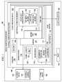
- Energy harvesting environment 100 is an example of one type of environment in which the different advantageous embodiments may be implemented to generate electrical energy 102 using thermal energy 104 .
- electrical energy 102 is generated from thermal energy 104 using structure 106 and energy harvesting device 108 in energy harvesting environment 100 .
- Structure 106 has first portion 110 and second portion 112 in these examples.
- Structure 106 may be any type of structure in which difference in temperature 114 may be generated.
- second portion 112 may be configured to be cooler than first portion 110 such that difference in temperature 114 is generated.
- Difference in temperature 114 may also be referred to as a temperature gradient. The temperature gradient is a gradual change in temperature.
- structure 106 takes the form of heat sink 116 .
- Heat sink 116 may be any object configured to transfer thermal energy 104 from first medium 118 having a higher temperature to second medium 120 having a cooler temperature.
- first medium 118 having the higher temperature takes the form of a solid medium
- second medium 120 having the cooler temperature takes the form of a fluid medium.
- the solid medium may be, for example, a metal material, a metal alloy material, plastic, and/or some other suitable type of solid material.
- the fluid medium may be, for example, a liquid, air, or some other type of fluid.
- first medium 118 may take the form of a fluid medium having a higher temperature than second medium 120 .
- second medium 120 may take the form of a solid medium.
- first medium 118 may be on or at a side of first portion 110 of heat sink 116, around first portion 110, and/or part of first portion 110.
- second medium 120 may be on or at a side of second portion 112 of heat sink 116, around second portion 112, and/or part of second portion 112.
- second portion 112 of heat sink 116 may comprise flexible elements 121 .
- Flexible elements 121 may be in the form of fins 123.
- a fin is a surface that extends from an object to increase the rate of heat transfer to or from the environment by increasing convection.
- fins 123 may be referred to as cooling fins when fins 123 are configured such that fins 123 have a cooler temperature than first portion 110 of heat sink 116 .
- Fins 123 may include straight fins, pin fins, curved fins, angled fins, and/or other suitable types of fins.
- difference in temperature 114 may be generated when a hot fluid flows near first portion 110 and a cold fluid is present around fins 123 .
- difference in temperature 114 may be generated when first portion 110 generates heat and fins 123 are surrounded by cold air.
- energy harvesting device 108 is formed as part of structure 106. Energy harvesting device 108 and structure 106 together form electrical current generation system 109 .
- energy harvesting device 108 is formed on surface 122 of structure 106 as part of structure 106 .
- Surface 122 may be an outer surface, inner surface, or some other suitable type of surface of structure 106 .
- Surface 122 may have a shape that is substantially planar or curved prior to energy harvesting device 108 being formed on surface 122.
- surface 122 may be substantially planar prior to energy harvesting device 108 being formed on surface 122 .
- structure 106 may be manipulated to change the shape of surface 122 to being curved.
- energy harvesting device 108 is configured to generate electrical energy 102 in the form of electrical current 124 when difference in temperature 114 between first portion 110 and second portion 112 of structure 106 is sufficient for generating electrical current 124 .
- energy harvesting device 108 when desired difference in temperature 126 is present between first portion 110 and second portion 112 , energy harvesting device 108 generates electrical current 124 .
- energy harvesting device 108 is formed on surface 122 of structure 106.
- first part 130 of energy harvesting device 108 may be formed on surface 122 of first portion 110 of structure 106
- second part 132 of energy harvesting device 108 may be formed on surface 122 of second portion 112 of structure 106.
- energy harvesting device 108 may comprise electrically conductive segments 128 .
- Electrically conductive segment 134 is an example of one of electrically conductive segments 128 .
- Electrically conductive segment 134 may comprise first metal section 136 and second metal section 138 .
- a first metal in first metal section 136 may be different from a second metal in second metal section 138 .
- first metal section 136 and second metal section 138 are comprised of dissimilar metals.
- first metal section 136 and second metal section 138 may be formed as part of structure 106 on surface 122 using a number of various processes. These processes may include at least one of spraying a first metal and a second metal onto surface 122 to form first metal section 136 and second metal section 138 , respectively, depositing the first metal and the second metal onto surface 122 , printing the first metal and the second metal onto surface 122 , sintering a powdered form of the first metal and the second metal onto surface 122 , chemical vapor deposition, electron beam epitaxy, molecular beam epitaxy, and/or some other suitable type of process.
- the phrase "at least one of”, when used with a list of items, means that different combinations of one or more of the listed items may be used and only one of each item in the list may be needed.
- “at least one of item A, item B, and item C” may include, for example, without limitation, item A, or item A and item B. This example also may include item A, item B, and item C, or item B and item C.
- First metal section 136 and second metal section 138 may have junction 140 at which first metal section 136 and second metal section 138 are connected to each other and/or placed near each other.
- a number of sections comprising various types of conductive material may be present between first metal section 136 and second metal section 138 at junction 140 .
- the temperature at the connection between first metal section 136 and the number of sections and the temperature at the connection between second metal section 138 and the number of sections is substantially the same.
- Junction 140 between first metal section 136 and second metal section 138 is configured such that the temperature of first metal section 136 and second metal section 138 changes along the length of these sections beginning at junction 140 .
- this change in temperature may be caused by difference in temperature 114 generated between first portion 110 and second portion 112 of structure 106 .
- electrically conductive segment 134 may have one or more additional junctions at which electrically conductive segment 134 is connected to another electrically conductive segment in electrically conductive segments 128 and/or an electrical device.
- desired difference in temperature 126 When desired difference in temperature 126 is present between first portion 110 and second portion 112, desired difference in temperature 126 is also present along first metal section 136 and second metal section 138 . A presence of desired difference in temperature 126 may cause electrically conductive segment 134 to generate electrical current 124 .
- electrically conductive segment 134 may take the form of a thermocouple.
- energy harvesting device 108 takes the form of a thermopile.
- a plurality of items means two or more items.
- a plurality of thermocouples means two or more thermocouples.
- the plurality of thermocouples may be connected to each other in parallel, in series, or in a combination of in parallel and in series.
- electrical system 142 may be electrically connected to electrically conductive segments 128 .
- first component such as electrical system 142
- second component such as one or more of electrically conductive segments 128
- the first component is connected to the second component such that an electrical signal can be sent from the first component to the second component, the second component to the first component, or a combination of the two.
- the first component may be electrically connected to the second component without any additional components between the two components.
- the first component also may be electrically connected to the second component by one or more other components.
- one electronic device may be electrically connected to a second electronic device without any additional electronic devices between the first electronic device and the second electronic device.
- another electronic device may be present between the two electronic devices that are electrically connected to each other.
- electrical system 142 may be connected to at least one of electrically conductive segments 128 .
- Electrical system 142 may be one or more electrical devices.
- an electrical device in electrical system 142 may take the form of, for example, without limitation, a sensor, a camera, a thermometer, a switch, a fan, a pump, a battery, a capacitor, a radio device, a wireless access port, and/or some other suitable type of electrical or electronic device.
- Electrically conductive segments 128 may supply electrical current 124 to electrical system 142 .
- electrical energy 102 in the form of electrical current 124 may be harvested by energy harvesting device 108 to supply power to electrical system 142 .
- structure 106 may be associated with another structure, such as object 144 .
- object 144 may be configured to generate heat to heat first portion 110 of structure 106.
- object 144 may be configured to transfer heat to first portion 110 of structure 106 such that first portion 110 has a higher temperature than second portion 112 .
- Object 144 may be associated with structure 106. For example, a portion of object 144 may be in contact with a portion of structure 106. As another example, object 144 may be placed near or close to structure 106 .
- structure 106 and object 144 may take various forms.
- structure 106 and/or object 144 may take the form of at least one of a pipe, a metal sheet, a tube, an exhaust tube, an engine exhaust, an engine intake, an exhaust manifold for an engine, a clamp, a band strap, a bulkhead, a beam, a floorboard, a floor beam, and/or some other suitable type of structure or object.
- structure 106 and/or object 144 may be associated with a platform.
- the platform may be selected from one of, for example, without limitation, a mobile platform, a stationary platform, a land-based structure, an aquatic-based structure, a space-based structure, an aircraft, a surface ship, a tank, a personnel carrier, a train, a spacecraft, a space station, a satellite, a submarine, an automobile, a power plant, a bridge, a dam, a manufacturing facility, a building, and/or some other suitable type of platform.
- second portion 112 of heat sink 116 may comprise rigid elements instead of flexible elements 121. These rigid elements may still be referred to as fins 123, depending on the implementation.
- more than one of energy harvesting device 108 may be formed as part of structure 106 .
- structure 106 may have additional portions in addition to first portion 110 and second portion 112, which are configured to have difference in temperature 114 .
- Additional energy harvesting devices may be formed as part of structure 106 to generate electrical current 124 based on the temperature difference between these other portions of structure 106 .
- more than one object 144 may be configured to generate heat to heat first portion 110 of structure 106 .
- more than one electrical device in electrical system 142 may be electrically connected to electrically conductive segments 128 .
- FIGS 2-15 illustrations of an energy harvesting device formed as part of a structure are depicted in accordance with an advantageous embodiment.
- Various configurations and uses of a structure with an energy harvesting device formed as part of the structure are shown in Figures 2-15 .
- the different components shown in these figures may be combined with components in Figure 1 , used with components in Figure 1 , or a combination of the two. Additionally, some of the components in these figures may be illustrative examples of how components shown in block form in Figure 1 can be implemented as physical structures.
- structure 200 is an example of one implementation for structure 106 in Figure 1 .
- Energy harvesting device 201 is an example of one implementation for energy harvesting device 108 in Figure 1 .
- structure 200 takes the form of metal sheet 202 in this example.
- Metal sheet 202 is substantially planar in this figure.
- Metal sheet 202 has side 203 and side 205 .
- Line 204 and line 206 indicate where metal sheet 202 may be bent when attaching structure 200 to another object.
- metal sheet 202 has first portion 208 and second portion 210 .
- First portion 208 is the area of metal sheet 202 between line 204 and line 206 .
- Second portion 210 includes the areas of metal sheet 202 extending outward from line 204 and line 206 .
- second portion 210 is non-contiguous and comprises different areas of metal sheet 202 .
- second portion 210 includes fins 212 .
- Fins 212 are examples of one implementation for flexible elements 121 in Figure 1 .
- metal sheet 202 may be cut to form fins 212 .
- energy harvesting device 201 is formed as part of metal sheet 202 .
- energy harvesting device 201 is formed as part of metal sheet 202 on surface 214 of metal sheet 202.
- Thermopile 215 is formed on surface 214 of metal sheet 202 such that first part 218 of thermopile 215 is formed on surface 214 of first portion 208 of metal sheet 202, and second part 220 of thermopile 215 is formed on surface 214 of second portion 210 of metal sheet 202.
- thermopile 215 comprises thermocouples 216.
- thermopile 215 may be formed on surface 214 by printing thermocouples 216 onto surface 214 of structure 200.
- Thermocouples 216 are connected in series in this illustrative example.
- thermocouple 224 and thermocouple 226 are connected in series on surface 214 of metal sheet 202.
- thermocouple 224 has first metal section 228 and second metal section 230 connected at junction 232.
- thermocouple 224 is connected to thermocouple 226 at junction 233.
- First metal section 228 is comprised of a different type of metal than then the type of metal comprising second metal section 230 in this illustrative example.
- first metal section 228 and second metal section 230 are comprised of dissimilar metals with respect to each other.
- thermocouples 216 also include thermocouple 234 , which may be connected to an electrical device in electrical system 142 in Figure 1 .
- thermocouple 234 may be connected to a sensor device in electrical system 142 in Figure 1 .
- FIG. 3 an illustration of a perspective view of structure 200 with energy harvesting device 201 formed on structure 200 associated with an object is depicted in accordance with an advantageous embodiment.
- structure 200 from Figure 2 is associated with object 300 .
- Object 300 is an example of one implementation for object 144 in Figure 1 .
- structure 200 is placed on object 300.
- Object 300 takes the form of duct tube 302 in this depicted example.
- duct tube 302 has curved surface 304.
- Structure 200 has been manipulated to conform to curved surface 304.
- metal sheet 202 has been bent along line 204 and line 206 such that first portion 208 of metal sheet 202 has a shape that conforms to curved surface 304 of duct tube 302 .
- the bending of metal sheet 202 along line 204 and line 206 causes second portion 210 of metal sheet 202 to extend away from curved surface 304 of duct tube 302 and away from first portion 208 of metal sheet 202. In this manner, fins 212 extend away from first portion 208 of metal sheet 202. Further, the bending of metal sheet 202 causes second part 220 of thermocouples 216 to extend away from first part 218 of thermocouples 216.
- hot fluid may flow through channel 306 of duct tube 302.
- the hot fluid may be, for example, a warm or hot liquid or warm or hot air.
- the hot fluid may cause duct tube 302 to heat. This heat may, in turn, heat first portion 208 of metal sheet 202.
- second portion 210 may be surrounded by cold air in this illustrative example.
- thermocouples 216 are configured to generate an electrical current. Thermocouples 216 may supply the electrical current to an electrical system such as, for example, a sensor device.
- FIG. 4 an illustration of a view of structure 200 from side 203 with energy harvesting device 201 formed on structure 200 associated with object 300 is depicted in accordance with an advantageous embodiment.
- energy harvesting device 201 may not be seen in this view.
- hot fluid may flow through channel 306 in duct tube 302.
- structure 200 is in the form of metal sheet 202 and has a different configuration as compared to the configuration of structure 200 in Figures 2-4 .
- metal sheet 202 has metal bands 500 , 502 , 504 , and 506 formed from metal sheet 202.
- Metal bands 500 , 502 , 504 , and 506 form third portion 508 of metal sheet 202 .
- Metal bands 500 , 502 , 504 , and 506 are bands configured to attach metal sheet 202 to an object, such as object 300 in Figure 3 .
- these metal bands may be referred to as attachment bands that allow metal sheet 202 to wrap around the object to attach metal sheet 202 to the object.
- FIG. 6 an illustration of structure 200 having metal bands 500 , 502 , 504 , and 506 attached to object 300 is depicted in accordance with an advantageous embodiment.
- metal bands 500 , 502 , 504 , and 506 are shown wrapped around object 300.
- Metal bands 500 , 502 , 504 , and 506 attach metal sheet 202 to object 300 .
- a component such as component 600 may be connected to thermocouples 216 at ends 602 of thermocouples 216.
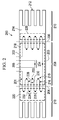
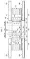
- lines 702 , 704 , 706 , and 708 are present for metal sheet 202 in addition to line 204 and line 206. Bending metal sheet 202 along lines 702 , 704 , 706, and 708 may form sections 710 , 712 , 714 , 716 , and 718 from first portion 208 of metal sheet 202 .
- FIG 8 an illustration of structure 200 bent along lines 702 , 704 , 706 , and 708 from Figure 7 and attached to object 300 is depicted in accordance with an advantageous embodiment.
- this bending of metal sheet 202 forms sections 710 , 712 , 714 , 716 , and 718 such that section 714 has separation 800 from curved surface 304 of object 300 in the form of duct tube 302 .
- Separation 800 allows a component, such as component 802 , to be mounted to section 714 of metal sheet 202 to remain thermally isolated from duct tube 302 .
- section 710 and section 718 of first portion 208 of metal sheet 202 are attached to curved surface 304 of duct tube 302 . This attachment allows heating of section 710 and section 718 when hot fluid passes through channel 306 of duct tube 302 .
- thermopiles in addition to or in place of thermopile 215 may be associated with structure 200.
- structure 200 may not take the form of metal sheet 202. Instead, structure 200 may be a sheet comprised of one or more materials in addition to and/or in place of metal.
- structure 200 may be comprised of materials comprising at least one of a metal, a metal alloy, a composite material, and/or any other suitable type of material that conducts heat with a desired level of thermal conductivity.
- a thermally conductive material is any material that conducts heat. These materials may include, for example, at least one of a composite material, a plastic comprising thermally conductive additives, a thermal paste, a metallic particle laced thermal paste, lithium, metal alloys, encapsulated liquids, carbon nanotube, formed ceramic, grapheme, diamond powder paste, and/or other suitable types of thermally conductive materials.
- a substantially non-electrically conductive material may be deposited between portions of structure 200 and thermocouples 216 .
- the substantially non-electrically conductive material may be deposited in a number of areas between locations for thermocouples 21 6 .
- This substantially non-electrically conductive material may reduce and/or prevent the possibility of an electrical short circuit between thermocouples 216 through the electrically conductive surface of structure 200 .
- the substantially non-electrically conductive material may be, for example, without limitation, a dielectric material, a ceramic, a spinel, and/or some other suitable type of material.
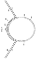
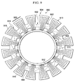
- structure 900 is an example of one implementation for structure 106 in Figure 1 .
- structure 900 takes the form of heat sink 902 .
- heat sink 902 is a metallic object that has circular shape 904 .
- Circular shape 904 allows heat sink 902 to slide over pipe 906.
- Pipe 906 is an example of one implementation for object 144 in Figure 1 .
- heat sink 902 has first portion 908 and second portion 910. Further, heat sink 902 has contact springs 912 connected to first portion 908. Contact springs 912 contact curved surface 914 of pipe 906 . Second portion 910 has fins 913 connected to first portion 908 of heat sink 902. Fins 913 are convection cooling fins in this illustrative example.
- thermopile 916 is printed or deposited on surface 918 of heat sink 902 .
- Thermopile 916 has sets of thermocouples connected in series in this example.
- Set of thermocouples 920 is an example of one of the sets of thermocouples in thermopile 916 .
- the thermocouples in set of thermocouples 920 are connected in series.
- thermopiles 916 may be connected to thermopiles 916 at terminals 922 to receive electrical current generated by thermopiles 916 .
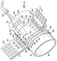
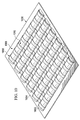
- object 1000 may be a metallic object.
- object 1000 may be comprised of other thermally conductive materials, such as composite materials.
- Supports 1002 are placed on surface 1004 of object 1000 .
- Supports 1002 provide a shape for forming thermally conductive strips using thermally conductive material.
- thermally conductive material 1006 has been sprayed over supports 1002 and surface 1004 of object 1000 to form thermally conductive strips 1008 .
- Thermally conductive material 1006 may be, for example, a metallic material and/or some other suitable type of thermally conductive material. These strips are formed substantially perpendicular to supports 1002. Further, as illustrated, supports 1002 are configured such that thermally conductive strips 1008 form curved shapes 1010.
- thermally conductive material 1006 may be deposited over supports 1002 and surface 1004 of object 1000 in some other suitable manner.
- thermally conductive material 1006 may be formed by printing or painting this material on surface 1004 and supports 1002 of object 1000 .
- Thermally conductive material 1006 may be a material that adheres to surface 1004 of object 1000 in locations where the material is sprayed on surface 1004 .
- a thermally conductive adhesive or some other type of mechanism may be used to adhere thermally conductive material 1006 to surface 1004 of object 1000 .
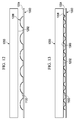
- FIG. 11 an illustration of object 1000 with springs extending from object 1000 is depicted in accordance with an advantageous embodiment.
- supports 1002 have been removed.
- Supports 1002 may be removed by, for example, without limitation, chemically dissolving supports 1002 , physically removing supports 1002 , melting supports 1002 , chemically etching supports 1002 , and/or performing some other suitable type of removal operation.
- thermally conductive strips 1008 form springs 1100 .
- Springs 1100 extend from surface 1004 of object 1000 . As depicted, more than one spring may be formed by each thermally conductive strip in thermally conductive strips 1008.
- FIG. 12 an illustration of a side view of springs 1100 extending from object 1000 is depicted in accordance with an advantageous embodiment.
- object 1000 has been moved into a position relative to object 1200 .
- springs 1100 are not in contact with surface 1202 of object 1200 .
- FIG. 13 an illustration of a side view of springs 1100 extending from object 1000 and in contact with object 1200 is depicted in accordance with an advantageous embodiment.
- object 1200 is placed over object 1000.
- surface 1202 of object 1200 contacts surface 1300 of springs 1100.
- installation of object 1000 causes contact between surface 1202 of object 1200 and surface 1300 of springs 1100 .
- This contact causes springs 1100 to deform and/or bend as shown such that locations of thermal contact between object 1200 and object 1000 may be formed.
- springs 1100 may be formed having other types of shapes other than curved shapes 1010 depicted in Figure 10 .
- aircraft 1400 has fuselage 1402. Further, aircraft 1400 also has floor beam 1404 that extends across fuselage 1402. For example, floor beam 1404 intersects with fuselage 1402 at section 1405.
- a difference in temperature is present between side 1406 of fuselage 1402 and side 1408 of fuselage 1402.
- the temperature inside of side 1406 of fuselage 1402 may be higher than the temperature on the outside of side 1408 of fuselage 1402 .
- a skin (not shown) may be present on side 1408 of fuselage 1402 for aircraft 1400 .
- side 1406 may be exposed to a first temperature.
- this first temperature is a temperature of the air inside fuselage 1402 or, in other words, the air inside the cabin of aircraft 1400. This first temperature may be about 20 degrees Celsius.
- Side 1408 of fuselage 1402 is exposed to a second temperature. This second temperature is a temperature of the air or environment around fuselage 1402 of aircraft 1400 . Side 1408 may be exposed to a second temperature that may be, for example, about negative 30 degrees Celsius.
- side 1406 is exposed to a first temperature that is higher than the second temperature to which side 1408 is exposed.
- the temperature may become cooler and cooler in a direction from side 1406 to side 1408 .
- This difference in temperature is a temperature gradient that may occur when aircraft 1400 is flying at high altitudes or is otherwise in use.
- FIG. 15 an illustration of an enlarged cross-sectional view of a section of an aircraft is depicted in accordance with an advantageous embodiment.
- section 1405 from Figure 15 is depicted in an enlarged view.
- thermopile 1500 and thermopile 1502 have been formed as part of fuselage 1402 and floor beam 1404.
- thermopile 1500 is formed as part of fuselage 1402.
- Thermopile 1500 may be deposited in an interior of fuselage 1402 during the manufacturing of fuselage 1402.
- the interior of fuselage 1402 is an interior of frame 1504 forming fuselage 1402.
- thermopile 1500 may be deposited on frame 1504 of fuselage 1402 before manufacturing of fuselage 1402 has been completed or as part of manufacturing fuselage 1402.
- Thermopile 1500 generates an electrical current in response to a temperature gradient caused by a difference in temperature between side 1406 and side 1408 of fuselage 1402.
- thermopile 1502 is formed as part of floor beam 1404 at or near an intersection of floor beam 1404 and frame 1504 of fuselage 1402 .
- thermopile 1502 may be deposited on a surface of floor beam 1404 in this illustrative example.
- Thermopile 1502 generates an electrical current in response to a temperature gradient caused by the difference in temperature between end 1506 of floor beam 1404 and portion 1508 of floor beam 1404 .
- Portion 1508 of floor beam 1404 is exposed to a first temperature that is higher than a second temperature to which end 1506 of floor beam 1404 is exposed.
- the air in the cabin inside fuselage 1402 has a higher temperature than the air outside fuselage 1402 .
- This difference in temperature may be greater when aircraft 1400 is flying at high altitudes and/or in use in some other manner as compared to when aircraft 1400 is flying at low altitudes, on the ground, and/or not in use.
- thermopiles may be formed in other locations within aircraft 1400 .
- thermopiles may be formed as part of an air vent, a wall, a door, a stringer, a rib, a bulkhead, an engine exhaust, an engine component, an engine mount, a floor truss, a fuel tank wall, a frame, and/or other suitable types of structures.
- FIG. 16 an illustration of a flowchart of a process for manufacturing an electrical current generation system is depicted in accordance with an advantageous embodiment. The process illustrated in Figure 16 may be implemented to form electrical current generation system 109 in Figure 1 .
- the process begins by forming a structure having a first portion and a second portion (operation 1600).
- the second portion is configured to have a lower temperature than a temperature of the first portion.
- the second portion of the structure may be exposed to a temperature that is lower than a temperature to which the first portion of the structure is exposed when the first portion of the structure is attached to a platform, connected to an object configured to generate heat, attached to a platform while the platform is in use, and/or heated in some other suitable manner.
- the process forms an energy harvesting device as part of the structure (operation 1602 ), with the process terminating thereafter.
- the energy harvesting device is configured to generate an electrical current when a desired difference in temperature is present between the first portion and the second portion. Operation 1602 may be performed in a number of different ways.
- the energy harvesting device may comprise electrically conductive segments that are sprayed onto a surface of the structure, deposited onto a surface of the structure, printed onto a surface of the structure, chemically applied to an interior of the structure, and/or formed as part of the structure in some other suitable manner.
- operation 1602 may be performed during operation 1600.
- operation 1602 may be performed to form the energy harvesting device in an interior of the structure prior to the forming of the structure being completed. Once the energy harvesting device has been formed, operation 1600 may then be completed to form the completed structure.
- FIG. 17 an illustration of a flowchart of a process for generating an electrical current is depicted in accordance with an advantageous embodiment.
- the process illustrated in Figure 17 may be implemented using electrical current generation system 109 in Figure 1 .
- the process begins by attaching an energy harvesting device to an object (operation 1700 ).
- the energy harvesting device is formed on a structure having a first portion and a second portion.
- the first portion of the structure has a higher temperature than the second portion.
- the structure is configured to transfer thermal energy from the first portion to the second portion.
- the process receives an electrical current from the energy harvesting device (operation 1702 ).
- the electrical current is generated in response to the transfer of thermal energy from the first portion of the structure to the second portion of the structure.
- the process then powers an electrical system using the electrical current received from the energy harvesting device (operation 1704 ), with the process terminating thereafter.
- the electrical system may, for example, comprise a sensor device that is connected to the energy harvesting system and configured to operate using the electrical current received from the energy harvesting device.
- each block in the flowchart or block diagrams may represent a module, segment, function, and/or a portion of an operation or step.
- one or more of the blocks may be implemented as program code, in hardware, or a combination of the program code and hardware.
- the hardware may, for example, take the form of integrated circuits that are manufactured or configured to perform one or more operations in the flowchart or block diagrams.
- the function or functions noted in the block may occur out of the order noted in the figures.
- two blocks shown in succession may be executed substantially concurrently, or the blocks may sometimes be executed in the reverse order, depending upon the functionality involved.
- other blocks may be added in addition to the illustrated blocks in a flowchart or block diagram.
- the different advantageous embodiments provide an apparatus comprising a structure.
- the structure is configured to have a first portion and a second portion in which the second portion has a lower temperature than a temperature of the first portion.
- the structure is configured to have an energy harvesting device formed as part of the structure.
- the energy harvesting device is configured to generate an electrical current when a desired difference in temperature is present between the first portion and the second portion.
- the different advantageous embodiments provide an energy harvesting device that is configured to span more widely-spaced temperature gradients as compared to currently used energy harvesting devices. Further, the different advantageous embodiments allow an energy harvesting device to be formed on both a first portion of a structure and a second portion of the structure that comprises cooling fins and has a lower temperature than the first portion.
Landscapes
- Measuring Temperature Or Quantity Of Heat (AREA)
- Cooling Or The Like Of Electrical Apparatus (AREA)
- Resistance Heating (AREA)
Applications Claiming Priority (2)
| Application Number | Priority Date | Filing Date | Title |
|---|---|---|---|
| US13/110,250 US8975503B2 (en) | 2011-05-18 | 2011-05-18 | Thermoelectric energy harvesting system |
| PCT/US2012/032326 WO2012158272A1 (en) | 2011-05-18 | 2012-04-05 | Thermoelectric energy harvesting system |
Publications (2)
| Publication Number | Publication Date |
|---|---|
| EP2710646A1 EP2710646A1 (en) | 2014-03-26 |
| EP2710646B1 true EP2710646B1 (en) | 2016-06-22 |
Family
ID=46051913
Family Applications (1)
| Application Number | Title | Priority Date | Filing Date |
|---|---|---|---|
| EP12720023.6A Active EP2710646B1 (en) | 2011-05-18 | 2012-04-05 | Thermoelectric energy harvesting system |
Country Status (6)
| Country | Link |
|---|---|
| US (1) | US8975503B2 (ja) |
| EP (1) | EP2710646B1 (ja) |
| JP (1) | JP6320916B2 (ja) |
| CN (1) | CN103534826B (ja) |
| ES (1) | ES2590490T3 (ja) |
| WO (1) | WO2012158272A1 (ja) |
Families Citing this family (19)
| Publication number | Priority date | Publication date | Assignee | Title |
|---|---|---|---|---|
| FR2977976A1 (fr) | 2011-07-13 | 2013-01-18 | St Microelectronics Rousset | Procede de generation d'energie electrique au sein d'une structure integree tridimensionnelle, et dispositif de liaison correspondant |
| US10283691B2 (en) | 2013-02-14 | 2019-05-07 | Dillard University | Nano-composite thermo-electric energy converter and fabrication method thereof |
| US9666781B2 (en) * | 2013-08-19 | 2017-05-30 | The Boeing Company | Methods for recovering waste energy from bleed air ducts |
| US10141492B2 (en) | 2015-05-14 | 2018-11-27 | Nimbus Materials Inc. | Energy harvesting for wearable technology through a thin flexible thermoelectric device |
| US10566515B2 (en) | 2013-12-06 | 2020-02-18 | Sridhar Kasichainula | Extended area of sputter deposited N-type and P-type thermoelectric legs in a flexible thin-film based thermoelectric device |
| US20180090660A1 (en) | 2013-12-06 | 2018-03-29 | Sridhar Kasichainula | Flexible thin-film based thermoelectric device with sputter deposited layer of n-type and p-type thermoelectric legs |
| US10367131B2 (en) | 2013-12-06 | 2019-07-30 | Sridhar Kasichainula | Extended area of sputter deposited n-type and p-type thermoelectric legs in a flexible thin-film based thermoelectric device |
| US10290794B2 (en) | 2016-12-05 | 2019-05-14 | Sridhar Kasichainula | Pin coupling based thermoelectric device |
| US11024789B2 (en) | 2013-12-06 | 2021-06-01 | Sridhar Kasichainula | Flexible encapsulation of a flexible thin-film based thermoelectric device with sputter deposited layer of N-type and P-type thermoelectric legs |
| US11276810B2 (en) | 2015-05-14 | 2022-03-15 | Nimbus Materials Inc. | Method of producing a flexible thermoelectric device to harvest energy for wearable applications |
| US11283000B2 (en) | 2015-05-14 | 2022-03-22 | Nimbus Materials Inc. | Method of producing a flexible thermoelectric device to harvest energy for wearable applications |
| EP3259189B1 (fr) * | 2015-06-02 | 2018-07-18 | Airbus Defence and Space SAS | Satellite artificiel |
| US20170005250A1 (en) * | 2015-06-30 | 2017-01-05 | The Boeing Company | Powering aircraft sensors using thermal capacitors |
| FR3039518B1 (fr) * | 2015-07-31 | 2018-05-04 | Airbus Helicopters | Stockage d'energie a piles thermiques pour aeronef a voilure tournante |
| JP6709040B2 (ja) * | 2015-11-18 | 2020-06-10 | 日東電工株式会社 | 半導体装置の製造方法 |
| US11616185B2 (en) | 2017-06-01 | 2023-03-28 | Qualcomm Incorporated | Energy harvesting device for electronic devices |
| CN114269406A (zh) * | 2019-04-05 | 2022-04-01 | 奇德尼实验室公司 | 用于肾脏治疗的吸着剂 |
| US11700682B2 (en) * | 2019-07-16 | 2023-07-11 | The Esab Group, Inc. | Thermoelectric cooling of consumables in a plasma torch |
| JP7468130B2 (ja) | 2020-05-14 | 2024-04-16 | 住友ゴム工業株式会社 | 二輪自動車用タイヤ |
Family Cites Families (19)
| Publication number | Priority date | Publication date | Assignee | Title |
|---|---|---|---|---|
| US1765563A (en) * | 1930-06-24 | Louis a | ||
| US2694098A (en) | 1950-05-23 | 1954-11-09 | Milwaukee Gas Specialty Co | Thermoelectric generator and method for production of same |
| US3284245A (en) | 1961-04-10 | 1966-11-08 | Lockheed Aircraft Corp | Thermoelectric generators |
| US3300840A (en) * | 1962-01-23 | 1967-01-31 | Marshall Maurice Bernard | Method of making thermoelectric generators |
| EP0190151B1 (en) * | 1984-05-24 | 1989-08-23 | SWARBRICK, Alan | Thermo-electric generator |
| JPH04252926A (ja) * | 1991-01-30 | 1992-09-08 | Ishikawajima Harima Heavy Ind Co Ltd | メタル温度計の取付方法 |
| JP2809299B2 (ja) * | 1993-09-16 | 1998-10-08 | 三菱電機株式会社 | 薄膜ヒータ型風速センサー |
| JPH11177154A (ja) * | 1997-12-09 | 1999-07-02 | Murata Mfg Co Ltd | 熱電変換基板及び当該熱電変換基板を用いた電気回路装置 |
| US6150601A (en) * | 1998-04-28 | 2000-11-21 | Halliburton Energy Services, Inc. | Method and apparatus for generating electric power downhole |
| US6075199A (en) * | 1998-04-29 | 2000-06-13 | National Research Council Of Canada | Body heat power generator |
| US7629531B2 (en) * | 2003-05-19 | 2009-12-08 | Digital Angel Corporation | Low power thermoelectric generator |
| JP2006300623A (ja) * | 2005-04-19 | 2006-11-02 | Matsushita Electric Works Ltd | 赤外線センサ |
| US7488888B2 (en) | 2006-09-15 | 2009-02-10 | The Boeing Company | Energy harvesting devices |
| JP2008192970A (ja) * | 2007-02-07 | 2008-08-21 | Tokai Rika Co Ltd | 熱電変換デバイス及びその製造方法 |
| GB2447333B (en) | 2007-03-09 | 2009-02-18 | Boeing Co | Energy harvesting devices |
| FR2917997B1 (fr) | 2007-06-29 | 2009-08-28 | Renault Sas | Systeme de regulation thermique de l'habitacle d'un vehicule |
| US7765811B2 (en) * | 2007-06-29 | 2010-08-03 | Laird Technologies, Inc. | Flexible assemblies with integrated thermoelectric modules suitable for use in extracting power from or dissipating heat from fluid conduits |
| DE102007055090B4 (de) | 2007-11-16 | 2013-03-14 | Eads Deutschland Gmbh | Überwachungsvorrichtung zur Überwachung der Außenhaut eines Luftfahrzeuges |
| FR2947529A1 (fr) | 2009-07-06 | 2011-01-07 | Airbus | Dispositif generateur d'energie electrique pour un avion, comprenant des generateurs thermoelectriques |
-
2011
- 2011-05-18 US US13/110,250 patent/US8975503B2/en active Active
-
2012
- 2012-04-05 CN CN201280023596.6A patent/CN103534826B/zh active Active
- 2012-04-05 JP JP2014511366A patent/JP6320916B2/ja active Active
- 2012-04-05 EP EP12720023.6A patent/EP2710646B1/en active Active
- 2012-04-05 WO PCT/US2012/032326 patent/WO2012158272A1/en active Application Filing
- 2012-04-05 ES ES12720023.6T patent/ES2590490T3/es active Active
Also Published As
| Publication number | Publication date |
|---|---|
| CN103534826A (zh) | 2014-01-22 |
| ES2590490T3 (es) | 2016-11-22 |
| JP6320916B2 (ja) | 2018-05-09 |
| US8975503B2 (en) | 2015-03-10 |
| WO2012158272A1 (en) | 2012-11-22 |
| EP2710646A1 (en) | 2014-03-26 |
| JP2014520499A (ja) | 2014-08-21 |
| CN103534826B (zh) | 2017-03-15 |
| US20120291425A1 (en) | 2012-11-22 |
Similar Documents
| Publication | Publication Date | Title |
|---|---|---|
| EP2710646B1 (en) | Thermoelectric energy harvesting system | |
| EP3525259B1 (en) | Aircraft or spacecraft having a structural component with a battery arrangement integrated therein | |
| US8294020B2 (en) | Energy harvesting devices | |
| US20190061970A1 (en) | Multi-rotor aerial drone with thermal energy harvesting | |
| CN105517899B (zh) | 用于热能采集和动力转换的系统 | |
| US20170170542A1 (en) | Vehicle Antenna Assembly With Cooling | |
| CN104466305B (zh) | 外承力筒飞行器蓄电池组热控装置 | |
| JPH1052077A (ja) | 熱電モジュール | |
| JP2007036178A (ja) | 熱電変換装置および冷暖装置 | |
| US20100091816A1 (en) | Temperature sensor | |
| GB2447333A (en) | Thermoelectric energy harvesting arrangement | |
| US10876456B2 (en) | Thermoelectric heat energy recovery module generator for application in a Stirling-electric hybrid automobile | |
| CN109326749B (zh) | 电池组模块和这种电池组模块的应用 | |
| EP3098898A1 (en) | Temperature control device for controlling the temperature of a battery, in particular of a motor vehicle | |
| Ancik et al. | Modeling, simulation and experimental testing of the MEMS thermoelectric generators in wide range of operational conditions | |
| JP2011254010A (ja) | 熱電変換装置 | |
| US11581466B2 (en) | Thermoelectric generator | |
| CA3039382C (en) | Variable band for thermoelectric modules | |
| EP3109910A1 (en) | Thermoelectric device | |
| US20180287232A1 (en) | Battery system | |
| US20240166358A1 (en) | System and method for generating electrical energy from thermal waste energy and removing thermal waste energy in an aircraft | |
| US20230225210A1 (en) | Powering sensor packages in moving platforms | |
| CN113453492A (zh) | 飞行器和用于热管理的方法 | |
| EP1980491A1 (en) | System and methods for power generation for spacecraft electronics | |
| KR20160081538A (ko) | 열전소자 및 축열소자를 구비한 차량 폐열 회수 시스템 |
Legal Events
| Date | Code | Title | Description |
|---|---|---|---|
| PUAI | Public reference made under article 153(3) epc to a published international application that has entered the european phase |
Free format text: ORIGINAL CODE: 0009012 |
|
| 17P | Request for examination filed |
Effective date: 20131218 |
|
| AK | Designated contracting states |
Kind code of ref document: A1 Designated state(s): AL AT BE BG CH CY CZ DE DK EE ES FI FR GB GR HR HU IE IS IT LI LT LU LV MC MK MT NL NO PL PT RO RS SE SI SK SM TR |
|
| DAX | Request for extension of the european patent (deleted) | ||
| GRAP | Despatch of communication of intention to grant a patent |
Free format text: ORIGINAL CODE: EPIDOSNIGR1 |
|
| INTG | Intention to grant announced |
Effective date: 20160107 |
|
| GRAS | Grant fee paid |
Free format text: ORIGINAL CODE: EPIDOSNIGR3 |
|
| GRAA | (expected) grant |
Free format text: ORIGINAL CODE: 0009210 |
|
| AK | Designated contracting states |
Kind code of ref document: B1 Designated state(s): AL AT BE BG CH CY CZ DE DK EE ES FI FR GB GR HR HU IE IS IT LI LT LU LV MC MK MT NL NO PL PT RO RS SE SI SK SM TR |
|
| REG | Reference to a national code |
Ref country code: GB Ref legal event code: FG4D |
|
| REG | Reference to a national code |
Ref country code: CH Ref legal event code: EP |
|
| REG | Reference to a national code |
Ref country code: IE Ref legal event code: FG4D |
|
| REG | Reference to a national code |
Ref country code: AT Ref legal event code: REF Ref document number: 808120 Country of ref document: AT Kind code of ref document: T Effective date: 20160715 |
|
| REG | Reference to a national code |
Ref country code: DE Ref legal event code: R096 Ref document number: 602012019740 Country of ref document: DE |
|
| REG | Reference to a national code |
Ref country code: LT Ref legal event code: MG4D |
|
| REG | Reference to a national code |
Ref country code: NL Ref legal event code: MP Effective date: 20160622 |
|
| PG25 | Lapsed in a contracting state [announced via postgrant information from national office to epo] |
Ref country code: LT Free format text: LAPSE BECAUSE OF FAILURE TO SUBMIT A TRANSLATION OF THE DESCRIPTION OR TO PAY THE FEE WITHIN THE PRESCRIBED TIME-LIMIT Effective date: 20160622 Ref country code: FI Free format text: LAPSE BECAUSE OF FAILURE TO SUBMIT A TRANSLATION OF THE DESCRIPTION OR TO PAY THE FEE WITHIN THE PRESCRIBED TIME-LIMIT Effective date: 20160622 Ref country code: NO Free format text: LAPSE BECAUSE OF FAILURE TO SUBMIT A TRANSLATION OF THE DESCRIPTION OR TO PAY THE FEE WITHIN THE PRESCRIBED TIME-LIMIT Effective date: 20160922 |
|
| REG | Reference to a national code |
Ref country code: AT Ref legal event code: MK05 Ref document number: 808120 Country of ref document: AT Kind code of ref document: T Effective date: 20160622 |
|
| REG | Reference to a national code |
Ref country code: ES Ref legal event code: FG2A Ref document number: 2590490 Country of ref document: ES Kind code of ref document: T3 Effective date: 20161122 |
|
| PG25 | Lapsed in a contracting state [announced via postgrant information from national office to epo] |
Ref country code: LV Free format text: LAPSE BECAUSE OF FAILURE TO SUBMIT A TRANSLATION OF THE DESCRIPTION OR TO PAY THE FEE WITHIN THE PRESCRIBED TIME-LIMIT Effective date: 20160622 Ref country code: SE Free format text: LAPSE BECAUSE OF FAILURE TO SUBMIT A TRANSLATION OF THE DESCRIPTION OR TO PAY THE FEE WITHIN THE PRESCRIBED TIME-LIMIT Effective date: 20160622 Ref country code: HR Free format text: LAPSE BECAUSE OF FAILURE TO SUBMIT A TRANSLATION OF THE DESCRIPTION OR TO PAY THE FEE WITHIN THE PRESCRIBED TIME-LIMIT Effective date: 20160622 Ref country code: NL Free format text: LAPSE BECAUSE OF FAILURE TO SUBMIT A TRANSLATION OF THE DESCRIPTION OR TO PAY THE FEE WITHIN THE PRESCRIBED TIME-LIMIT Effective date: 20160622 Ref country code: GR Free format text: LAPSE BECAUSE OF FAILURE TO SUBMIT A TRANSLATION OF THE DESCRIPTION OR TO PAY THE FEE WITHIN THE PRESCRIBED TIME-LIMIT Effective date: 20160923 Ref country code: RS Free format text: LAPSE BECAUSE OF FAILURE TO SUBMIT A TRANSLATION OF THE DESCRIPTION OR TO PAY THE FEE WITHIN THE PRESCRIBED TIME-LIMIT Effective date: 20160622 |
|
| PG25 | Lapsed in a contracting state [announced via postgrant information from national office to epo] |
Ref country code: EE Free format text: LAPSE BECAUSE OF FAILURE TO SUBMIT A TRANSLATION OF THE DESCRIPTION OR TO PAY THE FEE WITHIN THE PRESCRIBED TIME-LIMIT Effective date: 20160622 Ref country code: RO Free format text: LAPSE BECAUSE OF FAILURE TO SUBMIT A TRANSLATION OF THE DESCRIPTION OR TO PAY THE FEE WITHIN THE PRESCRIBED TIME-LIMIT Effective date: 20160622 Ref country code: IT Free format text: LAPSE BECAUSE OF FAILURE TO SUBMIT A TRANSLATION OF THE DESCRIPTION OR TO PAY THE FEE WITHIN THE PRESCRIBED TIME-LIMIT Effective date: 20160622 Ref country code: CZ Free format text: LAPSE BECAUSE OF FAILURE TO SUBMIT A TRANSLATION OF THE DESCRIPTION OR TO PAY THE FEE WITHIN THE PRESCRIBED TIME-LIMIT Effective date: 20160622 Ref country code: IS Free format text: LAPSE BECAUSE OF FAILURE TO SUBMIT A TRANSLATION OF THE DESCRIPTION OR TO PAY THE FEE WITHIN THE PRESCRIBED TIME-LIMIT Effective date: 20161022 Ref country code: SK Free format text: LAPSE BECAUSE OF FAILURE TO SUBMIT A TRANSLATION OF THE DESCRIPTION OR TO PAY THE FEE WITHIN THE PRESCRIBED TIME-LIMIT Effective date: 20160622 |
|
| PG25 | Lapsed in a contracting state [announced via postgrant information from national office to epo] |
Ref country code: PL Free format text: LAPSE BECAUSE OF FAILURE TO SUBMIT A TRANSLATION OF THE DESCRIPTION OR TO PAY THE FEE WITHIN THE PRESCRIBED TIME-LIMIT Effective date: 20160622 Ref country code: PT Free format text: LAPSE BECAUSE OF FAILURE TO SUBMIT A TRANSLATION OF THE DESCRIPTION OR TO PAY THE FEE WITHIN THE PRESCRIBED TIME-LIMIT Effective date: 20161024 Ref country code: AT Free format text: LAPSE BECAUSE OF FAILURE TO SUBMIT A TRANSLATION OF THE DESCRIPTION OR TO PAY THE FEE WITHIN THE PRESCRIBED TIME-LIMIT Effective date: 20160622 Ref country code: SM Free format text: LAPSE BECAUSE OF FAILURE TO SUBMIT A TRANSLATION OF THE DESCRIPTION OR TO PAY THE FEE WITHIN THE PRESCRIBED TIME-LIMIT Effective date: 20160622 Ref country code: BE Free format text: LAPSE BECAUSE OF FAILURE TO SUBMIT A TRANSLATION OF THE DESCRIPTION OR TO PAY THE FEE WITHIN THE PRESCRIBED TIME-LIMIT Effective date: 20160622 |
|
| REG | Reference to a national code |
Ref country code: DE Ref legal event code: R097 Ref document number: 602012019740 Country of ref document: DE |
|
| REG | Reference to a national code |
Ref country code: FR Ref legal event code: PLFP Year of fee payment: 6 |
|
| PLBE | No opposition filed within time limit |
Free format text: ORIGINAL CODE: 0009261 |
|
| STAA | Information on the status of an ep patent application or granted ep patent |
Free format text: STATUS: NO OPPOSITION FILED WITHIN TIME LIMIT |
|
| 26N | No opposition filed |
Effective date: 20170323 |
|
| PG25 | Lapsed in a contracting state [announced via postgrant information from national office to epo] |
Ref country code: DK Free format text: LAPSE BECAUSE OF FAILURE TO SUBMIT A TRANSLATION OF THE DESCRIPTION OR TO PAY THE FEE WITHIN THE PRESCRIBED TIME-LIMIT Effective date: 20160622 |
|
| PG25 | Lapsed in a contracting state [announced via postgrant information from national office to epo] |
Ref country code: SI Free format text: LAPSE BECAUSE OF FAILURE TO SUBMIT A TRANSLATION OF THE DESCRIPTION OR TO PAY THE FEE WITHIN THE PRESCRIBED TIME-LIMIT Effective date: 20160622 |
|
| REG | Reference to a national code |
Ref country code: CH Ref legal event code: PL |
|
| REG | Reference to a national code |
Ref country code: IE Ref legal event code: MM4A |
|
| PG25 | Lapsed in a contracting state [announced via postgrant information from national office to epo] |
Ref country code: MC Free format text: LAPSE BECAUSE OF FAILURE TO SUBMIT A TRANSLATION OF THE DESCRIPTION OR TO PAY THE FEE WITHIN THE PRESCRIBED TIME-LIMIT Effective date: 20160622 |
|
| PG25 | Lapsed in a contracting state [announced via postgrant information from national office to epo] |
Ref country code: LU Free format text: LAPSE BECAUSE OF NON-PAYMENT OF DUE FEES Effective date: 20170405 Ref country code: CH Free format text: LAPSE BECAUSE OF NON-PAYMENT OF DUE FEES Effective date: 20170430 Ref country code: LI Free format text: LAPSE BECAUSE OF NON-PAYMENT OF DUE FEES Effective date: 20170430 |
|
| REG | Reference to a national code |
Ref country code: FR Ref legal event code: PLFP Year of fee payment: 7 |
|
| PG25 | Lapsed in a contracting state [announced via postgrant information from national office to epo] |
Ref country code: IE Free format text: LAPSE BECAUSE OF NON-PAYMENT OF DUE FEES Effective date: 20170405 |
|
| PG25 | Lapsed in a contracting state [announced via postgrant information from national office to epo] |
Ref country code: MT Free format text: LAPSE BECAUSE OF NON-PAYMENT OF DUE FEES Effective date: 20170405 |
|
| PG25 | Lapsed in a contracting state [announced via postgrant information from national office to epo] |
Ref country code: AL Free format text: LAPSE BECAUSE OF FAILURE TO SUBMIT A TRANSLATION OF THE DESCRIPTION OR TO PAY THE FEE WITHIN THE PRESCRIBED TIME-LIMIT Effective date: 20160622 |
|
| PG25 | Lapsed in a contracting state [announced via postgrant information from national office to epo] |
Ref country code: HU Free format text: LAPSE BECAUSE OF FAILURE TO SUBMIT A TRANSLATION OF THE DESCRIPTION OR TO PAY THE FEE WITHIN THE PRESCRIBED TIME-LIMIT; INVALID AB INITIO Effective date: 20120405 |
|
| PG25 | Lapsed in a contracting state [announced via postgrant information from national office to epo] |
Ref country code: BG Free format text: LAPSE BECAUSE OF FAILURE TO SUBMIT A TRANSLATION OF THE DESCRIPTION OR TO PAY THE FEE WITHIN THE PRESCRIBED TIME-LIMIT Effective date: 20160622 |
|
| PG25 | Lapsed in a contracting state [announced via postgrant information from national office to epo] |
Ref country code: CY Free format text: LAPSE BECAUSE OF NON-PAYMENT OF DUE FEES Effective date: 20160622 |
|
| PG25 | Lapsed in a contracting state [announced via postgrant information from national office to epo] |
Ref country code: MK Free format text: LAPSE BECAUSE OF FAILURE TO SUBMIT A TRANSLATION OF THE DESCRIPTION OR TO PAY THE FEE WITHIN THE PRESCRIBED TIME-LIMIT Effective date: 20160622 |
|
| PG25 | Lapsed in a contracting state [announced via postgrant information from national office to epo] |
Ref country code: TR Free format text: LAPSE BECAUSE OF FAILURE TO SUBMIT A TRANSLATION OF THE DESCRIPTION OR TO PAY THE FEE WITHIN THE PRESCRIBED TIME-LIMIT Effective date: 20160622 |
|
| REG | Reference to a national code |
Ref country code: DE Ref legal event code: R082 Ref document number: 602012019740 Country of ref document: DE Representative=s name: KILBURN & STRODE LLP, NL |
|
| REG | Reference to a national code |
Ref country code: DE Ref legal event code: R079 Ref document number: 602012019740 Country of ref document: DE Free format text: PREVIOUS MAIN CLASS: H01L0035320000 Ipc: H10N0010170000 |
|
| P01 | Opt-out of the competence of the unified patent court (upc) registered |
Effective date: 20230516 |
|
| PGFP | Annual fee paid to national office [announced via postgrant information from national office to epo] |
Ref country code: GB Payment date: 20240429 Year of fee payment: 13 |
|
| PGFP | Annual fee paid to national office [announced via postgrant information from national office to epo] |
Ref country code: DE Payment date: 20240429 Year of fee payment: 13 |
|
| PGFP | Annual fee paid to national office [announced via postgrant information from national office to epo] |
Ref country code: ES Payment date: 20240503 Year of fee payment: 13 |
|
| PGFP | Annual fee paid to national office [announced via postgrant information from national office to epo] |
Ref country code: FR Payment date: 20240425 Year of fee payment: 13 |