EP2709796B1 - Dispositif oscillant à logement de pièce et à masse d'équilibrage, et procede - Google Patents
Dispositif oscillant à logement de pièce et à masse d'équilibrage, et procede Download PDFInfo
- Publication number
- EP2709796B1 EP2709796B1 EP12762520.0A EP12762520A EP2709796B1 EP 2709796 B1 EP2709796 B1 EP 2709796B1 EP 12762520 A EP12762520 A EP 12762520A EP 2709796 B1 EP2709796 B1 EP 2709796B1
- Authority
- EP
- European Patent Office
- Prior art keywords
- workpiece
- vibrating
- frequency
- receiving portion
- compensating mass
- Prior art date
- Legal status (The legal status is an assumption and is not a legal conclusion. Google has not performed a legal analysis and makes no representation as to the accuracy of the status listed.)
- Not-in-force
Links
- 238000000034 method Methods 0.000 title claims description 8
- 238000003754 machining Methods 0.000 claims description 16
- 238000003801 milling Methods 0.000 claims description 8
- 230000001105 regulatory effect Effects 0.000 claims description 8
- 238000002604 ultrasonography Methods 0.000 claims description 8
- 230000001133 acceleration Effects 0.000 claims description 7
- 239000000110 cooling liquid Substances 0.000 claims description 4
- 230000001276 controlling effect Effects 0.000 claims description 3
- 238000001816 cooling Methods 0.000 claims description 3
- 239000004519 grease Substances 0.000 claims 1
- 230000010355 oscillation Effects 0.000 description 9
- 238000012545 processing Methods 0.000 description 5
- 238000006073 displacement reaction Methods 0.000 description 4
- 239000000463 material Substances 0.000 description 4
- 238000005520 cutting process Methods 0.000 description 3
- 229910000760 Hardened steel Inorganic materials 0.000 description 2
- 229910010293 ceramic material Inorganic materials 0.000 description 2
- 150000001875 compounds Chemical class 0.000 description 2
- 230000000694 effects Effects 0.000 description 2
- 230000005284 excitation Effects 0.000 description 2
- 238000011010 flushing procedure Methods 0.000 description 2
- 239000000758 substrate Substances 0.000 description 2
- 238000012360 testing method Methods 0.000 description 2
- 229910052581 Si3N4 Inorganic materials 0.000 description 1
- VYPSYNLAJGMNEJ-UHFFFAOYSA-N Silicium dioxide Chemical compound O=[Si]=O VYPSYNLAJGMNEJ-UHFFFAOYSA-N 0.000 description 1
- 239000010426 asphalt Substances 0.000 description 1
- 230000015572 biosynthetic process Effects 0.000 description 1
- 239000003575 carbonaceous material Substances 0.000 description 1
- 239000000919 ceramic Substances 0.000 description 1
- 238000004891 communication Methods 0.000 description 1
- 238000010276 construction Methods 0.000 description 1
- 239000002826 coolant Substances 0.000 description 1
- 239000005068 cooling lubricant Substances 0.000 description 1
- 238000011161 development Methods 0.000 description 1
- 238000005553 drilling Methods 0.000 description 1
- 238000005516 engineering process Methods 0.000 description 1
- 238000002474 experimental method Methods 0.000 description 1
- 230000002349 favourable effect Effects 0.000 description 1
- 239000011521 glass Substances 0.000 description 1
- 238000000227 grinding Methods 0.000 description 1
- 238000002347 injection Methods 0.000 description 1
- 239000007924 injection Substances 0.000 description 1
- 238000004519 manufacturing process Methods 0.000 description 1
- 238000003913 materials processing Methods 0.000 description 1
- 230000003534 oscillatory effect Effects 0.000 description 1
- 238000000206 photolithography Methods 0.000 description 1
- 238000005498 polishing Methods 0.000 description 1
- 238000011160 research Methods 0.000 description 1
- 238000007789 sealing Methods 0.000 description 1
- HQVNEWCFYHHQES-UHFFFAOYSA-N silicon nitride Chemical compound N12[Si]34N5[Si]62N3[Si]51N64 HQVNEWCFYHHQES-UHFFFAOYSA-N 0.000 description 1
- 229910052814 silicon oxide Inorganic materials 0.000 description 1
- 239000002210 silicon-based material Substances 0.000 description 1
- 230000008093 supporting effect Effects 0.000 description 1
- 238000007514 turning Methods 0.000 description 1
Images


Classifications
-
- B—PERFORMING OPERATIONS; TRANSPORTING
- B23—MACHINE TOOLS; METAL-WORKING NOT OTHERWISE PROVIDED FOR
- B23Q—DETAILS, COMPONENTS, OR ACCESSORIES FOR MACHINE TOOLS, e.g. ARRANGEMENTS FOR COPYING OR CONTROLLING; MACHINE TOOLS IN GENERAL CHARACTERISED BY THE CONSTRUCTION OF PARTICULAR DETAILS OR COMPONENTS; COMBINATIONS OR ASSOCIATIONS OF METAL-WORKING MACHINES, NOT DIRECTED TO A PARTICULAR RESULT
- B23Q1/00—Members which are comprised in the general build-up of a form of machine, particularly relatively large fixed members
- B23Q1/25—Movable or adjustable work or tool supports
- B23Q1/26—Movable or adjustable work or tool supports characterised by constructional features relating to the co-operation of relatively movable members; Means for preventing relative movement of such members
- B23Q1/34—Relative movement obtained by use of deformable elements, e.g. piezoelectric, magnetostrictive, elastic or thermally-dilatable elements
-
- B—PERFORMING OPERATIONS; TRANSPORTING
- B24—GRINDING; POLISHING
- B24B—MACHINES, DEVICES, OR PROCESSES FOR GRINDING OR POLISHING; DRESSING OR CONDITIONING OF ABRADING SURFACES; FEEDING OF GRINDING, POLISHING, OR LAPPING AGENTS
- B24B41/00—Component parts such as frames, beds, carriages, headstocks
- B24B41/007—Weight compensation; Temperature compensation; Vibration damping
-
- B—PERFORMING OPERATIONS; TRANSPORTING
- B23—MACHINE TOOLS; METAL-WORKING NOT OTHERWISE PROVIDED FOR
- B23C—MILLING
- B23C9/00—Details or accessories so far as specially adapted to milling machines or cutter
-
- B—PERFORMING OPERATIONS; TRANSPORTING
- B23—MACHINE TOOLS; METAL-WORKING NOT OTHERWISE PROVIDED FOR
- B23Q—DETAILS, COMPONENTS, OR ACCESSORIES FOR MACHINE TOOLS, e.g. ARRANGEMENTS FOR COPYING OR CONTROLLING; MACHINE TOOLS IN GENERAL CHARACTERISED BY THE CONSTRUCTION OF PARTICULAR DETAILS OR COMPONENTS; COMBINATIONS OR ASSOCIATIONS OF METAL-WORKING MACHINES, NOT DIRECTED TO A PARTICULAR RESULT
- B23Q1/00—Members which are comprised in the general build-up of a form of machine, particularly relatively large fixed members
- B23Q1/25—Movable or adjustable work or tool supports
- B23Q1/64—Movable or adjustable work or tool supports characterised by the purpose of the movement
-
- B—PERFORMING OPERATIONS; TRANSPORTING
- B23—MACHINE TOOLS; METAL-WORKING NOT OTHERWISE PROVIDED FOR
- B23Q—DETAILS, COMPONENTS, OR ACCESSORIES FOR MACHINE TOOLS, e.g. ARRANGEMENTS FOR COPYING OR CONTROLLING; MACHINE TOOLS IN GENERAL CHARACTERISED BY THE CONSTRUCTION OF PARTICULAR DETAILS OR COMPONENTS; COMBINATIONS OR ASSOCIATIONS OF METAL-WORKING MACHINES, NOT DIRECTED TO A PARTICULAR RESULT
- B23Q3/00—Devices holding, supporting, or positioning work or tools, of a kind normally removable from the machine
- B23Q3/02—Devices holding, supporting, or positioning work or tools, of a kind normally removable from the machine for mounting on a work-table, tool-slide, or analogous part
- B23Q3/04—Devices holding, supporting, or positioning work or tools, of a kind normally removable from the machine for mounting on a work-table, tool-slide, or analogous part adjustable in inclination
-
- B—PERFORMING OPERATIONS; TRANSPORTING
- B23—MACHINE TOOLS; METAL-WORKING NOT OTHERWISE PROVIDED FOR
- B23Q—DETAILS, COMPONENTS, OR ACCESSORIES FOR MACHINE TOOLS, e.g. ARRANGEMENTS FOR COPYING OR CONTROLLING; MACHINE TOOLS IN GENERAL CHARACTERISED BY THE CONSTRUCTION OF PARTICULAR DETAILS OR COMPONENTS; COMBINATIONS OR ASSOCIATIONS OF METAL-WORKING MACHINES, NOT DIRECTED TO A PARTICULAR RESULT
- B23Q3/00—Devices holding, supporting, or positioning work or tools, of a kind normally removable from the machine
- B23Q3/02—Devices holding, supporting, or positioning work or tools, of a kind normally removable from the machine for mounting on a work-table, tool-slide, or analogous part
- B23Q3/10—Auxiliary devices, e.g. bolsters, extension members
-
- B—PERFORMING OPERATIONS; TRANSPORTING
- B30—PRESSES
- B30B—PRESSES IN GENERAL
- B30B15/00—Details of, or accessories for, presses; Auxiliary measures in connection with pressing
- B30B15/30—Feeding material to presses
- B30B15/302—Feeding material in particulate or plastic state to moulding presses
- B30B15/304—Feeding material in particulate or plastic state to moulding presses by using feed frames or shoes with relative movement with regard to the mould or moulds
-
- Y—GENERAL TAGGING OF NEW TECHNOLOGICAL DEVELOPMENTS; GENERAL TAGGING OF CROSS-SECTIONAL TECHNOLOGIES SPANNING OVER SEVERAL SECTIONS OF THE IPC; TECHNICAL SUBJECTS COVERED BY FORMER USPC CROSS-REFERENCE ART COLLECTIONS [XRACs] AND DIGESTS
- Y10—TECHNICAL SUBJECTS COVERED BY FORMER USPC
- Y10T—TECHNICAL SUBJECTS COVERED BY FORMER US CLASSIFICATION
- Y10T409/00—Gear cutting, milling, or planing
- Y10T409/30—Milling
- Y10T409/303752—Process
-
- Y—GENERAL TAGGING OF NEW TECHNOLOGICAL DEVELOPMENTS; GENERAL TAGGING OF CROSS-SECTIONAL TECHNOLOGIES SPANNING OVER SEVERAL SECTIONS OF THE IPC; TECHNICAL SUBJECTS COVERED BY FORMER USPC CROSS-REFERENCE ART COLLECTIONS [XRACs] AND DIGESTS
- Y10—TECHNICAL SUBJECTS COVERED BY FORMER USPC
- Y10T—TECHNICAL SUBJECTS COVERED BY FORMER US CLASSIFICATION
- Y10T409/00—Gear cutting, milling, or planing
- Y10T409/30—Milling
- Y10T409/303976—Milling with means to control temperature or lubricate
-
- Y—GENERAL TAGGING OF NEW TECHNOLOGICAL DEVELOPMENTS; GENERAL TAGGING OF CROSS-SECTIONAL TECHNOLOGIES SPANNING OVER SEVERAL SECTIONS OF THE IPC; TECHNICAL SUBJECTS COVERED BY FORMER USPC CROSS-REFERENCE ART COLLECTIONS [XRACs] AND DIGESTS
- Y10—TECHNICAL SUBJECTS COVERED BY FORMER USPC
- Y10T—TECHNICAL SUBJECTS COVERED BY FORMER US CLASSIFICATION
- Y10T409/00—Gear cutting, milling, or planing
- Y10T409/30—Milling
- Y10T409/304312—Milling with means to dampen vibration
-
- Y—GENERAL TAGGING OF NEW TECHNOLOGICAL DEVELOPMENTS; GENERAL TAGGING OF CROSS-SECTIONAL TECHNOLOGIES SPANNING OVER SEVERAL SECTIONS OF THE IPC; TECHNICAL SUBJECTS COVERED BY FORMER USPC CROSS-REFERENCE ART COLLECTIONS [XRACs] AND DIGESTS
- Y10—TECHNICAL SUBJECTS COVERED BY FORMER USPC
- Y10T—TECHNICAL SUBJECTS COVERED BY FORMER US CLASSIFICATION
- Y10T409/00—Gear cutting, milling, or planing
- Y10T409/30—Milling
- Y10T409/30868—Work support
- Y10T409/30896—Work support with angular adjustment
Definitions
- the invention relates to a device with a workpiece holder for receiving a workpiece to be machined, wherein at least one vibrating device is in communication with the workpiece holder and the vibrating device vibrates the workpiece holder, wherein the vibration of the workpiece holder has a frequency which is lower than the frequency of ultrasound, and a method of machining a workpiece, wherein the workpiece is vibrated and the frequency of the vibration of the workpiece is lower than the frequency of ultrasound.
- a tool is vibrated in the ultrasonic range, wherein as the oscillation frequency, preferably the natural frequency of the tool is selected so that deliberately resonant vibrations occur, which in particular during the machining of a workpiece, a supporting effect is achieved.
- a tool stimulated in the ultrasound field is known, for example, from the publication " Modeling of material removal rate in rotary ultrasonic machining: designed experiments "by P. Hu, JM Zhang, ZJ Pei, and Clyde Treadwell disclosed in the Journal of Materials Processing Technology 129, 2002, 339-344 has been published. Furthermore, from the publication “ Development of a Novel Ultrasound System for Implementing Flexible Ultrasonic Assisted Scattering "by T. Tavawoli, B. Azarhoushang, N. Jandaghi, published in the journal” Science & Research "2010, 28-33 , Various variants for vibrational excitation on the workpiece side known, which excite workpieces on resonators in the ultrasonic range.
- a frame is shown with a plate mounted therein including workpiece holder, wherein the plate is connected to the frame by piezoelectric elements.
- the plate and with her the workpiece can be placed in horizontal, vertical or rotating vibration.
- the intended frequency of the generated vibration is not more than 1500 Hz.
- the US 2004/008331 A1 shows a photolithography apparatus having a base frame and a substrate table which is moved relative to an exposure unit connected to the base frame.
- the substrate table is not directly, but connected via a balancing mass to the base frame, wherein the connection between the balancing mass and the base frame is elastic.
- the object of the present invention is to provide a method and a device for the mechanical machining of workpieces with which or which various mechanical machining operations can be performed on a workpiece by means of or with the aid of a swinging movement of the workpiece itself.
- a resonant oscillation should be avoided in the device according to the invention, as this could lead to damage of the device, and thus the frequency can be chosen freely without risk of damage.
- the oscillating device comprises a vibrating body, which is associated with a vibrating in the opposite direction balancing mass.
- the oscillating body of the oscillating device gegen Eisen oscillating balancing mass thus a pulse decoupling can be achieved, so that regardless of the natural frequency of the workpiece holder or the entire device any frequency for machining the workpiece can be adjusted.
- the device according to the invention in which the workpiece holder is vibrated by means of a vibrating device, which has a lower frequency than the frequency of ultrasound, can be used for a variety of purposes.
- a workpiece received in the workpiece holder can be subjected to a helical or a trochoidal machining by a corresponding control of the oscillating device.
- the device can also be used for hybrid processing, i. the vibration-assisted mechanical machining of workpieces mounted in the workpiece holder, are used.
- Mechanical operations in connection with the present invention are to be understood as meaning, in particular, any machining with geometrically defined or geometrically indefinite cutting edges; This includes in particular turning, drilling, milling, reaming and grinding, honing, lapping and polishing.
- the device can of course also be used for positioning the workpiece arranged in the workpiece holder with the aid of the oscillating device.
- the device may be similar to known devices in which, however, the tool is excited in the ultrasonic range to assist in the machining of difficult-to-machine materials, i. especially hard and / or brittle materials, e.g. Ceramics, glass, a variety of silicon materials such as silicon nitride or silicon oxide, but also hardened steel or the like can be used.
- the frequency of the vibration of the workpiece holder is less than 10 kHz, preferably less than 5 kHz, in particular less than 1 kHz, more preferably between 500 Hz and 50 Hz.
- the balancing mass may have an identical to the vibrating body mass; In this case, the balancing mass is vibrated at the same frequency and the same acceleration as the vibrating body, but in the opposite direction of movement. If the vibrating body and balancing mass do not have the same mass, a compensating inertia effect can be achieved by adjusting the acceleration. If the balancing mass has a lower mass than the oscillating body, it is therefore advantageous for pulse compensation if the compensating mass oscillates at the same frequency as and a larger amplitude than the vibrating body. Consequently, the balancing weight oscillates at the same frequency as the Oscillating, but has a higher acceleration and thus sets at the same frequency a greater way back.
- the oscillating device has at least one piezoelectric element.
- any type of vibration of the vibrating body in one plane i. e.g. a circular, diagonal, etc. shape of the oscillating movement
- piezoelectric elements are provided for displacement of the oscillating body in a plane.
- the piezoelectric elements can each be supported in a simple manner on the one hand on the outside on a housing surrounding the oscillating device and on the other hand on a preferably substantially centrally arranged abutment projection on the oscillating body.
- a control or regulating device is provided, with which opposite movements of the piezo elements, which are associated with the oscillating body, and those piezo elements, which are associated with the balancing mass, controlled or be managed. It is advantageous if associated with the oscillating body and the balancing mass displacement and / or acceleration sensors whose measured values are supplied as actual variables of the control or regulating device.
- the vibrating body and / or the balancing mass are mounted on at least one air bearing.
- a plate-shaped workpiece holder which is mounted on a cover plate of a base body, preferably by means of an air bearing.
- the plate-shaped workpiece holder also called machine table, mounted directly on an adjacent cover plate, so any tilting forces acting on the workpiece holder, no leverage is offered.
- the plate-shaped workpiece holder In order to further reduce the moments resulting from the movement forces, it is expedient for the plate-shaped workpiece holder to be fixedly connected to a counterplate, wherein the compensating mass is arranged between the plate-shaped workpiece holder and the counterplate.
- the device can, for example, only be moved in one plane, but at the same time a spatial change relative to the tool is achieved due to the differing direction of oscillation with respect to the movement of the tool.
- Tests have shown that it is particularly advantageous if a tool, preferably a milling tool, provided for machining, cooled by means of a coolant, is provided. It has been found that due to the vibrations of the workpiece received in or on the workpiece holder, a significantly improved flushing behavior of the chips mixed with chips is achieved, resulting in a significantly improved removal of the material already removed from the workpiece. Tests were in this case carried out in particular in connection with plate-shaped, ceramic materials.
- the method of the initially cited type is characterized in that, in order to avoid resonance vibrations of the workpiece and the machine tool, the pulse introduced to generate the oscillation is actively decoupled by means of a balancing mass oscillating in the opposite direction, preferably the frequency of the oscillation of the workpiece being less than 10 kHz, preferably below 5 kHz, in particular below 1 kHz, more preferably between 500 Hz and 50 Hz.
- a balancing mass oscillating in the opposite direction preferably the frequency of the oscillation of the workpiece being less than 10 kHz, preferably below 5 kHz, in particular below 1 kHz, more preferably between 500 Hz and 50 Hz.
- the balancing mass for impulse decoupling advantageously oscillates at the same frequency and a greater amplitude than the vibrating body.
- the impulse decoupling here is advantageously actively regulated, as already described in connection with the device according to the invention.
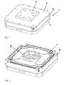
- Fig. 1 schematically a device 1 with a workpiece holder 2 is shown, wherein it can be seen that the device 1 has an upper cover plate 3 and a lower cover plate 4, between which a circumferential housing 5 is received.
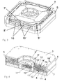
- a balance mass 7 added between the upper and lower cover plates 3, 4 and within the housing 5, as in Fig. 2 can be seen.
- the balancing mass 7 is intended to by a vibrating body 8 (see. Fig. 4 ) to decouple actively introduced inertia pulses, so that in particular resonant vibrations in a machine tool (see milling cutter 27 in Fig. 8a to 8d ), which is a tool 27 'for machining a workpiece 28 mounted on the device 1 (cf. Fig. 8a to 8d ) having, be avoided.
- the oscillating body 8 as well as the leveling compound 7 are part of a vibration device 9 accommodated in the housing 5, which is intended to cause the workpiece holder 2 to vibrate.
- a vibration device 9 accommodated in the housing 5, which is intended to cause the workpiece holder 2 to vibrate.
- the oscillating device 9 has rod-shaped piezo elements 10, 10 'as actuators, which in particular in FIG Fig. 3 can be seen.
- two rod-shaped piezo elements 10, 10 ' are provided on each side of the preferably substantially square housing 5.
- the piezoelectric elements 10 displace the oscillating body 8 (including the workpiece holder 2) into the desired oscillation, whereas the piezoelement 10 'arranged thereover displaces the leveling compound 7.
- the piezoelements 10, 10' are respectively supported on the housing 5 on the one hand Corner regions has a recess 5 ', and on the other hand at substantially centrally arranged contact projections 8' and 7 'of the oscillating body 8 and the balancing mass 7th
- the two arranged on one longitudinal side piezoelectric elements 10 and 10 ' are in this case interconnected such that they in the opposite direction of a control or regulating device 11 (see. Fig. 5 ).
- a control or regulating device 11 see. Fig. 5 .
- two so-called piezo stacks are combined in a rod-shaped piezoelectric element 10, 10'; Piezostacks of this kind are commercially available and are used, for example, for controlling injection nozzles in the automotive industry.
- piezoelectric elements 10, 10 ' which are composed of two piezo stacks, vibrations whose amplitude is up to +/- 60 microns, preferably +/- 20 microns, can be achieved.
- two piezo elements 10, 10 ' are provided, which are driven the same, as on the opposite side of the oscillating body 8 and the balancing mass 7 arranged piezo elements 10, 10 '.
- the piezoelectric elements 10, 10 'arranged substantially at a right angle thereto are controlled independently, so that the oscillating body 8 or the compensating mass 7 can execute any desired movement, for example a diagonal, or a circular movement.
- a recess 11 ' is provided in a support plate 11 of the oscillating body 8, in which a planar sliding bearing element 12', preferably made of a carbon material, is received.
- the balancing mass 7 is formed in cross-section substantially I-shaped, so that in the region between the two transverse legs, above and below a connecting leg 13 each have a receiving chamber 14 'is formed in the likewise each planar slide bearing elements 12' to form a Air bearing 12 are included.
- compressed air at a pressure of about 2 to 6 bar is introduced via a not shown in detail air supply line, so that the oscillating body 8 and the balancing mass 7 can swing substantially frictionless.
- the connecting element 2 'defined central recess can supply and discharge of compressed air into or out of the recesses 11', 14 'of the air bearing 12.
- a further actuator could be provided in this recess for the purpose of vibrational excitation in a vertical z-direction, so that not only the substantially parallel to the cover plates 3, 4 arranged piezo elements 10, 10 'in x and y with the help of the device
- any vibration eg a diagonal, a circular, sinusoidal vibration or the like, can be performed, but also in the normal direction to this level an additional vibration of the workpiece holder 2 in the z-direction can be achieved.
- the oscillating device 9 thus has four degrees of freedom - taking into account the rotation about the z-direction.
- the lower cover plate 4, the base plate 11, the housing 5 and the upper cover plate 3 are connected to each other via screws, not shown, which are screwed into the openings 16 provided for this purpose.
- the workpiece holder base is 2 'with the oscillating body 8 and the workpiece holder 2 via (not shown) screws which are screwed into the receiving openings 17, connected to each other.
- a control or regulating device 15 assigned to the device 1 via which a generator 15 'is driven, which supplies the piezoelectric elements 10, 10' with the corresponding electrical pulses, so that the oscillating device 9 with the desired frequency and the desired amplitude is vibrated.
- a generator 15 ' is driven, which supplies the piezoelectric elements 10, 10' with the corresponding electrical pulses, so that the oscillating device 9 with the desired frequency and the desired amplitude is vibrated.
- the path traveled by the balancing mass 7 and the vibrating body 8 and their acceleration is then transmitted via sensors, inter alia via a displacement sensor 15 '' (cf. Fig. 4 ), wherein via lines 15 '''the measured path or the measured acceleration is transmitted to the controller 15, so that a control loop is closed and thus an actively controlled pulse decoupling is achieved over which reliably desired resonance vibrations can be avoided.
- the control unit 15 is an operating unit 18 is switched, via which the operator can enter the desired frequency, amplitude, direction of vibration, etc.; Similarly, the control unit 15 is a numerical control 19 (NC unit) of a machine tool 27 switched on.
- Fig. 6 schematically a five-axis positioning device 20 is shown, on which the device 1 is positioned with the workpiece holder 2. Due to the five axes 21, over which the position device can be adjusted, a mechanical processing of complex 3D contours of the recorded on the workpiece holder 2 workpiece can be done.
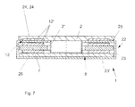
- a base body 22 is provided which Preferably, a housing 23 having a bottom surface 23 ', on which a cover plate 24 can be fastened.
- the plate-shaped workpiece holder 2 also called machine table, mounted by means of an air bearing 12;
- air bearing elements 12 'between the cover plate 24 and the workpiece holder 2 are arranged.
- a sealing element 25 between the workpiece holder 2 and the cover plate 24 is arranged to protect the air bearing 12 from the ingress of cooling lubricants and chips.
- the balance mass 7 is added, which oscillates in the opposite direction to the vibrating body 8 for momentum decoupling;
- the vibrating body 8 in this case has a base plate 26 which is connected via a preferably cylindrical connecting element 2 'with the plate-shaped workpiece holder, which is thus also part of the oscillating body 8.
- the vibrating body 8 and the balancing mass 7 are - as in connection with the principalsbespiel according to the FIGS. 1 to 5 already described in detail - connected to the oscillating device 9; ie on the oscillating body 8 and on the compensating mass 7 engage in the opposite direction vibrating piezoelectric elements 10, 10 '.
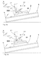
- FIGS. 8a to 8d various uses of the device 1 are shown, wherein the device is introduced in each case in a basic coordinate system (x, y, z).
- the oscillating device 9 itself has a relative coordinate system (x ', y', z ') in which the actuators oscillate.
- the device 1 can thus - as in the FIGS. 8a to 8d shown - tilted relative to the base coordinate system to be arranged; this is done by the angles ⁇ , ⁇ , ⁇ .
- the oscillatory movement then takes place in the direction of the relative coordinate system, whereas the tool 27 'of the machine tool 27 can be moved in any direction 29 in the base coordinate system, preferably along one of the coordinate main axes.
- a workpiece 28 fastened on the workpiece holder 2 can again be made by angular devices 30 along the orientation from the base coordinate system.
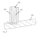
- a cooling liquid 31 (cf. Fig. 9 ), which is supplied for cooling the tool 27 'of a machine tool, such as a milling cutter 27, in the area to be machined, in the machining of hard plates 28, for example, hardened steel, ceramic materials or the like. Is vibrated. As a result, chips removed by the tool 27 'due to the vibrations of the cooling liquid 31 are transported much better.
- the cooling liquid 31 is in this case usually supplied to the area to be processed via a cooling channel 32 formed in the tool 27 '.
Landscapes
- Engineering & Computer Science (AREA)
- Mechanical Engineering (AREA)
- Auxiliary Devices For Machine Tools (AREA)
- Turning (AREA)
Claims (17)
- Dispositif (1) comprenant un logement pour pièces à usiner (2) servant à loger une pièce à usiner (28) à usiner mécaniquement, sachant qu'au moins un dispositif oscillant (9) est relié au logement pour pièces à usiner (2) et que le dispositif oscillant (9) entraîne l'oscillation du logement pour pièces à usiner (2), sachant que l'oscillation du logement pour pièces à usiner (2) présente une fréquence, qui est inférieure à la fréquence des ultrasons, caractérisé en ce que le dispositif d'oscillation (9) présente un corps oscillant (8), auquel est associée une masse d'équilibrage (7) qui oscille dans le sens opposé.
- Dispositif selon la revendication 1, caractérisé en ce que la fréquence de l'oscillation du logement pour pièces à usiner (2) est inférieure à 10 kHz, de préférence inférieure à 5 kHz, en particulier inférieure à 1 kHz, et de manière particulièrement préférée comprise entre 500 Hz et 50 Hz.
- Dispositif selon la revendication 1 ou 2, caractérisé en ce que la masse d'équilibrage (7) oscille à la même fréquence que le corps oscillant (8) et à une amplitude plus importante que celle du corps oscillant (8).
- Dispositif selon l'une quelconque des revendications 1 à 3, caractérisé en ce que le dispositif oscillant (9) présente au moins un élément piézoélectrique (10, 10').
- Dispositif selon la revendication 4, caractérisé en ce qu'au moins deux éléments piézoélectriques (10) présentant des sens de déplacement agencés de préférence de manière perpendiculaire les uns aux autres sont prévus aux fins du déplacement par coulissement du corps oscillant (8) dans un plan.
- Dispositif selon l'une quelconque de la revendication 4 ou 5, caractérisé en ce que sensiblement le même type et le même nombre d'éléments piézoélectriques (10') viennent en prise au niveau de la masse d'équilibrage (7) et au niveau du corps oscillant (8).
- Dispositif selon l'une quelconque des revendications 4 à 6, caractérisé en ce qu'un dispositif de commande ou de réglage (11) est prévu, lequel permet de commander ou de régler des mouvements diamétralement opposés des éléments piézoélectriques (10) qui sont associés au corps oscillant (8), et desdits éléments piézoélectriques (10') qui sont associés à la masse d'équilibrage (7).
- Dispositif selon la revendication 7, caractérisé en ce que des capteurs de trajectoire et/ou d'accélération sont associés au corps oscillant (8) et à la masse d'équilibrage (7), dont les valeurs de mesure sont fournies en tant que grandeurs réelles du dispositif de commande ou de réglage (11).
- Dispositif selon l'une quelconque des revendications 1 à 8, caractérisé en ce que le corps oscillant (8) et/ou la masse d'équilibrage (7) sont logés sur au moins un palier à air (12).
- Dispositif selon l'une quelconque des revendications 1 à 9, caractérisé en ce qu'un logement pour pièces à usiner (2) présentant une forme de plateau est prévu, lequel est logé sur un plateau de recouvrement (24) d'un corps de base, de préférence au moyen d'un palier à air (12).
- Dispositif selon la revendication 10, caractérisé en ce que le logement pour pièces à usiner (2) présentant une forme de plateau est relié de manière solidaire à un plateau complémentaire (26), sachant que la masse d'équilibrage (7) est disposée entre le logement pour pièces à usiner (2) présentant une forme de plateau et le plateau complémentaire.
- Dispositif selon l'une quelconque des revendications 1 à 11, caractérisé en ce que le dispositif (1) est disposé sur un dispositif de positionnement (20).
- Dispositif selon la revendication 12, caractérisé en ce qu'il est possible d'ajuster jusqu'à cinq axes du dispositif de positionnement (20).
- Dispositif (1) selon l'une quelconque des revendications 1 à 13, caractérisé en ce qu'au moins un sens d'oscillation (x', y', z') du dispositif oscillant (9) diverge d'un sens de déplacement (29) d'un outil (27') d'usinage par enlèvement de copeaux, de préférence d'une fraise.
- Dispositif (1) selon l'une quelconque des revendications 1 à 14, caractérisé en ce qu'est prévu un outil (27'), de préférence une fraise, prévu aux fins de l'usinage par enlèvement de copeaux, refroidi au moyen d'un liquide de refroidissement (31) ou au moyen d'un réfrigérant lubrifiant.
- Procédé servant à l'usinage mécanique d'une pièce à usiner (28), la pièce à usiner (28) étant amenée à osciller et la fréquence de l'oscillation de la pièce à usiner (28) étant inférieure à la fréquence des ultrasons, caractérisé en ce que l'impulsion donnée par l'oscillation à la pièce à usiner (28) est activement découplée au moyen d'une masse d'équilibrage (7) oscillant dans le sens opposé.
- Procédé selon la revendication 16, caractérisé en ce que la fréquence de l'oscillation de la pièce à usiner (28) est inférieure à 10 kHz, de préférence inférieure à 5 kHz, en particulier inférieure à 1 kHz, et de manière particulièrement préférée comprise entre 500 Hz et 50 Hz.
Applications Claiming Priority (2)
| Application Number | Priority Date | Filing Date | Title |
|---|---|---|---|
| ATA706/2011A AT511551B1 (de) | 2011-05-18 | 2011-05-18 | Vorrichtung und verfahren zur mechanischen bearbeitung eines werkstücks |
| PCT/AT2012/000137 WO2012167288A1 (fr) | 2011-05-18 | 2012-05-18 | Dispositif oscillant à logement de pièce et à masse d'équilibrage |
Publications (2)
| Publication Number | Publication Date |
|---|---|
| EP2709796A1 EP2709796A1 (fr) | 2014-03-26 |
| EP2709796B1 true EP2709796B1 (fr) | 2014-09-17 |
Family
ID=46207816
Family Applications (1)
| Application Number | Title | Priority Date | Filing Date |
|---|---|---|---|
| EP12762520.0A Not-in-force EP2709796B1 (fr) | 2011-05-18 | 2012-05-18 | Dispositif oscillant à logement de pièce et à masse d'équilibrage, et procede |
Country Status (5)
| Country | Link |
|---|---|
| US (1) | US9346139B2 (fr) |
| EP (1) | EP2709796B1 (fr) |
| CN (1) | CN103547412B (fr) |
| AT (1) | AT511551B1 (fr) |
| WO (1) | WO2012167288A1 (fr) |
Cited By (1)
| Publication number | Priority date | Publication date | Assignee | Title |
|---|---|---|---|---|
| DE102015101167A1 (de) | 2015-01-27 | 2016-07-28 | Technische Universität Wien | Spindelanordnung |
Families Citing this family (10)
| Publication number | Priority date | Publication date | Assignee | Title |
|---|---|---|---|---|
| WO2014033905A1 (fr) * | 2012-08-31 | 2014-03-06 | Minami Hironori | Procédé et dispositif de traitement d'un verre trempé |
| DE102013110728B4 (de) * | 2013-09-27 | 2021-08-19 | Ev Group E. Thallner Gmbh | System und Verfahren zum spanenden Bearbeiten eines Werkstücks |
| US9517512B2 (en) * | 2014-09-26 | 2016-12-13 | Chuan Liang Industrial Co., Ltd. | Ultrasonic positioning device for five-axis machine |
| EP3536451A1 (fr) * | 2018-03-07 | 2019-09-11 | Horst Knäbel | Procédé et dispositif d'amélioration de la coaxialité et de la capacité de charge d'un raccordement conique comportant un logement sous la forme d'anneau fermé et un manchon pouvant être élargi ou comprimé |
| CN108705329B (zh) * | 2018-08-22 | 2023-08-22 | 金陵科技学院 | 基于二自由度压电作动器的精密工作台及对应压电作动器 |
| DE102018127275B3 (de) * | 2018-10-31 | 2020-03-12 | Asm Assembly Systems Gmbh & Co. Kg | Bauelement-Zuführvorrichtung und Verfahren zum Bereitstellen von vereinzelten Bauelementen mittels Vibration, Bestücksystem |
| CN109894965B (zh) * | 2019-04-11 | 2023-12-01 | 哈尔滨汽轮机厂有限责任公司 | 一种用于数控铣床研磨环状工件的辅助装置及研磨方法 |
| CN111215644B (zh) * | 2020-02-17 | 2021-05-04 | 中国工程物理研究院机械制造工艺研究所 | 超声振动辅助切削反馈信号检测与补偿装置及方法、应用 |
| CN112405033B (zh) * | 2020-10-15 | 2022-06-14 | 渤海造船厂集团有限公司 | 一种垫片机加工用可调平台及其方法 |
| US12000455B2 (en) * | 2022-03-10 | 2024-06-04 | Taiwan Semiconductor Manufacturing Company, Ltd. | Systems and methods for reducing vibration of apparatuses |
Family Cites Families (14)
| Publication number | Priority date | Publication date | Assignee | Title |
|---|---|---|---|---|
| JPH0722876B2 (ja) * | 1987-06-24 | 1995-03-15 | 新技術事業団 | 研削用ワークテーブル装置 |
| DE4113667A1 (de) * | 1991-04-26 | 1992-11-05 | Fraunhofer Ges Forschung | Piezo-stellantrieb |
| US6241435B1 (en) * | 1998-03-25 | 2001-06-05 | Vought Aircraft Industries, Inc. | Universal adaptive machining chatter control fixture |
| JP3947501B2 (ja) * | 2002-06-07 | 2007-07-25 | エーエスエムエル ネザーランズ ビー.ブイ. | リソグラフィ用機器およびデバイスの製造方法 |
| DE10307308B4 (de) * | 2003-02-20 | 2006-11-30 | Siemens Ag | Einrichtung zum linearen Verfahren einer Nutzmasse |
| DK176725B1 (da) * | 2003-07-04 | 2009-05-04 | Kvm Industrimaskiner As | Fremgangsmåde til fremstilling af et vibrationsbord til betonstöbemaskiner samt et vibrationsbrod fremstillet ifölge fremgangsmåden |
| JP4396518B2 (ja) * | 2004-12-28 | 2010-01-13 | トヨタ自動車株式会社 | 姿勢制御装置および精密加工装置 |
| US7508116B2 (en) * | 2005-09-07 | 2009-03-24 | Panasonic Corporation | Method and apparatus for vibration machining with two independent axes |
| DE102005056603B4 (de) * | 2005-11-28 | 2019-02-21 | Siemens Aktiengesellschaft | Verfahren zur Reduktion von während eines Bearbeitungsvorgangs auftretenden Schwingungen eines Maschinenelementes und/oder eines Werkstücks |
| DE102005057175B4 (de) * | 2005-11-30 | 2009-03-26 | Siemens Ag | Verfahren zur Reduktion von Schwingungen eines Maschinenelements und/oder eines Werkstücks |
| CN101104244A (zh) | 2006-07-10 | 2008-01-16 | 宁波工程学院 | 超声波磁粒复合研磨方法及其装置 |
| DE102006049867B4 (de) * | 2006-10-23 | 2021-09-16 | Siemens Aktiengesellschaft | Werkzeugmaschine und Verfahren zur Unterdrückung von Ratterschwingungen |
| US7687975B2 (en) * | 2007-03-27 | 2010-03-30 | Panasonic Corporation | Vibration assisted machining system with stacked actuators |
| DE102010055288A1 (de) * | 2010-12-21 | 2012-06-21 | Ev Group Gmbh | Vorrichtung zum spanenden Bearbeiten eines Werkstücks |
-
2011
- 2011-05-18 AT ATA706/2011A patent/AT511551B1/de not_active IP Right Cessation
-
2012
- 2012-05-18 US US14/118,440 patent/US9346139B2/en not_active Expired - Fee Related
- 2012-05-18 EP EP12762520.0A patent/EP2709796B1/fr not_active Not-in-force
- 2012-05-18 CN CN201280023898.3A patent/CN103547412B/zh not_active Expired - Fee Related
- 2012-05-18 WO PCT/AT2012/000137 patent/WO2012167288A1/fr not_active Ceased
Cited By (2)
| Publication number | Priority date | Publication date | Assignee | Title |
|---|---|---|---|---|
| DE102015101167A1 (de) | 2015-01-27 | 2016-07-28 | Technische Universität Wien | Spindelanordnung |
| US11097391B2 (en) | 2015-01-27 | 2021-08-24 | Technische Universität Wien | Spindle arrangement |
Also Published As
| Publication number | Publication date |
|---|---|
| EP2709796A1 (fr) | 2014-03-26 |
| US20140093322A1 (en) | 2014-04-03 |
| AT511551B1 (de) | 2013-10-15 |
| WO2012167288A1 (fr) | 2012-12-13 |
| US9346139B2 (en) | 2016-05-24 |
| CN103547412A (zh) | 2014-01-29 |
| AT511551A1 (de) | 2012-12-15 |
| CN103547412B (zh) | 2016-05-04 |
Similar Documents
| Publication | Publication Date | Title |
|---|---|---|
| EP2709796B1 (fr) | Dispositif oscillant à logement de pièce et à masse d'équilibrage, et procede | |
| EP2655006B1 (fr) | Dispositif à deux composantes d'oscillation pour l'usinage par enlèvement de copeaux d'une pièce et procede pour celui-ci | |
| DE3879448T2 (de) | Vorrichtung, um ein zu schleifendes werkstueck ins schwingen zu bringen. | |
| DE3873765T2 (de) | Werkzeugmaschine zum ultraschallschleifen. | |
| WO1999048191A1 (fr) | Entrainement direct decouple des impulsions | |
| DE102010048636A1 (de) | Werkzeugmaschine, Werkstückbearbeitungsverfahren | |
| DE102010048638A1 (de) | Werkzeugmaschine, Werkstückbearbeitungsverfahren | |
| CN108145179A (zh) | 微纳结构加工机床及微纳结构加工方法 | |
| EP3210718A2 (fr) | Unité de traitement pour une machine-outil et machine-outil comprenant une telle unité de traitement | |
| WO2022232859A1 (fr) | Procédé et dispositif d'élimination de structures de support d'un objet | |
| WO2012052525A1 (fr) | Dispositif pour assurer mouvement hautement dynamique du point d'action d'un faisceau | |
| WO2011023185A2 (fr) | Dispositif de compensation de couples de rotation résultant de l'accélération d'axes supplémentaires redondants sur des machines-outils et des machines à mesurer, au moyen d'une pluralité de masses d'équilibrage à mouvement linéaire coordonné | |
| AT513094B1 (de) | Vorrichtung, insbesondere Spanwerkzeug | |
| EP2374574A1 (fr) | Machine à empierrer haute vitesse | |
| EP3509791B1 (fr) | Dispositif de polissage par vibration | |
| DE102014119141B4 (de) | Oszillierend antreibbare Werkzeugmaschine, Werkzeug, Koppelelement und System | |
| DE19945584A1 (de) | Mehrdimensionaler Antrieb für Arbeitsmaschinen | |
| DE10161243B4 (de) | Mikrostrukturierung mit ultraschallunterstütztem Schleifen | |
| DE102005038108A1 (de) | Vorrichtung und Verfahren zum Bearbeiten von Oberflächen | |
| EP4291387A1 (fr) | Procédé de prévention de dommages dus à la résonance lors du nettoyage d'un élément fabriqué au moins partiellement de manière additive, et dispositif de nettoyage | |
| CH655883A5 (en) | Method of producing tool electrodes for electrical discharge machining and apparatus for carrying it out |
Legal Events
| Date | Code | Title | Description |
|---|---|---|---|
| PUAI | Public reference made under article 153(3) epc to a published international application that has entered the european phase |
Free format text: ORIGINAL CODE: 0009012 |
|
| 17P | Request for examination filed |
Effective date: 20131118 |
|
| AK | Designated contracting states |
Kind code of ref document: A1 Designated state(s): AL AT BE BG CH CY CZ DE DK EE ES FI FR GB GR HR HU IE IS IT LI LT LU LV MC MK MT NL NO PL PT RO RS SE SI SK SM TR |
|
| GRAP | Despatch of communication of intention to grant a patent |
Free format text: ORIGINAL CODE: EPIDOSNIGR1 |
|
| INTG | Intention to grant announced |
Effective date: 20140422 |
|
| GRAS | Grant fee paid |
Free format text: ORIGINAL CODE: EPIDOSNIGR3 |
|
| GRAA | (expected) grant |
Free format text: ORIGINAL CODE: 0009210 |
|
| DAX | Request for extension of the european patent (deleted) | ||
| AK | Designated contracting states |
Kind code of ref document: B1 Designated state(s): AL AT BE BG CH CY CZ DE DK EE ES FI FR GB GR HR HU IE IS IT LI LT LU LV MC MK MT NL NO PL PT RO RS SE SI SK SM TR |
|
| REG | Reference to a national code |
Ref country code: GB Ref legal event code: FG4D Free format text: NOT ENGLISH |
|
| REG | Reference to a national code |
Ref country code: CH Ref legal event code: EP |
|
| REG | Reference to a national code |
Ref country code: IE Ref legal event code: FG4D Free format text: LANGUAGE OF EP DOCUMENT: GERMAN |
|
| REG | Reference to a national code |
Ref country code: AT Ref legal event code: REF Ref document number: 687455 Country of ref document: AT Kind code of ref document: T Effective date: 20141015 Ref country code: CH Ref legal event code: NV Representative=s name: RENTSCH PARTNER AG, CH |
|
| REG | Reference to a national code |
Ref country code: DE Ref legal event code: R096 Ref document number: 502012001285 Country of ref document: DE Effective date: 20141106 |
|
| PG25 | Lapsed in a contracting state [announced via postgrant information from national office to epo] |
Ref country code: FI Free format text: LAPSE BECAUSE OF FAILURE TO SUBMIT A TRANSLATION OF THE DESCRIPTION OR TO PAY THE FEE WITHIN THE PRESCRIBED TIME-LIMIT Effective date: 20140917 Ref country code: NO Free format text: LAPSE BECAUSE OF FAILURE TO SUBMIT A TRANSLATION OF THE DESCRIPTION OR TO PAY THE FEE WITHIN THE PRESCRIBED TIME-LIMIT Effective date: 20141217 Ref country code: GR Free format text: LAPSE BECAUSE OF FAILURE TO SUBMIT A TRANSLATION OF THE DESCRIPTION OR TO PAY THE FEE WITHIN THE PRESCRIBED TIME-LIMIT Effective date: 20141218 Ref country code: LT Free format text: LAPSE BECAUSE OF FAILURE TO SUBMIT A TRANSLATION OF THE DESCRIPTION OR TO PAY THE FEE WITHIN THE PRESCRIBED TIME-LIMIT Effective date: 20140917 Ref country code: SE Free format text: LAPSE BECAUSE OF FAILURE TO SUBMIT A TRANSLATION OF THE DESCRIPTION OR TO PAY THE FEE WITHIN THE PRESCRIBED TIME-LIMIT Effective date: 20140917 |
|
| REG | Reference to a national code |
Ref country code: NL Ref legal event code: VDEP Effective date: 20140917 |
|
| REG | Reference to a national code |
Ref country code: LT Ref legal event code: MG4D |
|
| PG25 | Lapsed in a contracting state [announced via postgrant information from national office to epo] |
Ref country code: LV Free format text: LAPSE BECAUSE OF FAILURE TO SUBMIT A TRANSLATION OF THE DESCRIPTION OR TO PAY THE FEE WITHIN THE PRESCRIBED TIME-LIMIT Effective date: 20140917 Ref country code: HR Free format text: LAPSE BECAUSE OF FAILURE TO SUBMIT A TRANSLATION OF THE DESCRIPTION OR TO PAY THE FEE WITHIN THE PRESCRIBED TIME-LIMIT Effective date: 20140917 Ref country code: CY Free format text: LAPSE BECAUSE OF FAILURE TO SUBMIT A TRANSLATION OF THE DESCRIPTION OR TO PAY THE FEE WITHIN THE PRESCRIBED TIME-LIMIT Effective date: 20140917 Ref country code: RS Free format text: LAPSE BECAUSE OF FAILURE TO SUBMIT A TRANSLATION OF THE DESCRIPTION OR TO PAY THE FEE WITHIN THE PRESCRIBED TIME-LIMIT Effective date: 20140917 |
|
| PG25 | Lapsed in a contracting state [announced via postgrant information from national office to epo] |
Ref country code: NL Free format text: LAPSE BECAUSE OF FAILURE TO SUBMIT A TRANSLATION OF THE DESCRIPTION OR TO PAY THE FEE WITHIN THE PRESCRIBED TIME-LIMIT Effective date: 20140917 |
|
| PG25 | Lapsed in a contracting state [announced via postgrant information from national office to epo] |
Ref country code: RO Free format text: LAPSE BECAUSE OF FAILURE TO SUBMIT A TRANSLATION OF THE DESCRIPTION OR TO PAY THE FEE WITHIN THE PRESCRIBED TIME-LIMIT Effective date: 20140917 Ref country code: ES Free format text: LAPSE BECAUSE OF FAILURE TO SUBMIT A TRANSLATION OF THE DESCRIPTION OR TO PAY THE FEE WITHIN THE PRESCRIBED TIME-LIMIT Effective date: 20140917 Ref country code: EE Free format text: LAPSE BECAUSE OF FAILURE TO SUBMIT A TRANSLATION OF THE DESCRIPTION OR TO PAY THE FEE WITHIN THE PRESCRIBED TIME-LIMIT Effective date: 20140917 Ref country code: IS Free format text: LAPSE BECAUSE OF FAILURE TO SUBMIT A TRANSLATION OF THE DESCRIPTION OR TO PAY THE FEE WITHIN THE PRESCRIBED TIME-LIMIT Effective date: 20150117 Ref country code: PT Free format text: LAPSE BECAUSE OF FAILURE TO SUBMIT A TRANSLATION OF THE DESCRIPTION OR TO PAY THE FEE WITHIN THE PRESCRIBED TIME-LIMIT Effective date: 20150119 Ref country code: CZ Free format text: LAPSE BECAUSE OF FAILURE TO SUBMIT A TRANSLATION OF THE DESCRIPTION OR TO PAY THE FEE WITHIN THE PRESCRIBED TIME-LIMIT Effective date: 20140917 Ref country code: SK Free format text: LAPSE BECAUSE OF FAILURE TO SUBMIT A TRANSLATION OF THE DESCRIPTION OR TO PAY THE FEE WITHIN THE PRESCRIBED TIME-LIMIT Effective date: 20140917 |
|
| PG25 | Lapsed in a contracting state [announced via postgrant information from national office to epo] |
Ref country code: PL Free format text: LAPSE BECAUSE OF FAILURE TO SUBMIT A TRANSLATION OF THE DESCRIPTION OR TO PAY THE FEE WITHIN THE PRESCRIBED TIME-LIMIT Effective date: 20140917 |
|
| REG | Reference to a national code |
Ref country code: DE Ref legal event code: R097 Ref document number: 502012001285 Country of ref document: DE |
|
| PLBE | No opposition filed within time limit |
Free format text: ORIGINAL CODE: 0009261 |
|
| STAA | Information on the status of an ep patent application or granted ep patent |
Free format text: STATUS: NO OPPOSITION FILED WITHIN TIME LIMIT |
|
| PG25 | Lapsed in a contracting state [announced via postgrant information from national office to epo] |
Ref country code: DK Free format text: LAPSE BECAUSE OF FAILURE TO SUBMIT A TRANSLATION OF THE DESCRIPTION OR TO PAY THE FEE WITHIN THE PRESCRIBED TIME-LIMIT Effective date: 20140917 |
|
| 26N | No opposition filed |
Effective date: 20150618 |
|
| PG25 | Lapsed in a contracting state [announced via postgrant information from national office to epo] |
Ref country code: IT Free format text: LAPSE BECAUSE OF FAILURE TO SUBMIT A TRANSLATION OF THE DESCRIPTION OR TO PAY THE FEE WITHIN THE PRESCRIBED TIME-LIMIT Effective date: 20140917 |
|
| PG25 | Lapsed in a contracting state [announced via postgrant information from national office to epo] |
Ref country code: SI Free format text: LAPSE BECAUSE OF FAILURE TO SUBMIT A TRANSLATION OF THE DESCRIPTION OR TO PAY THE FEE WITHIN THE PRESCRIBED TIME-LIMIT Effective date: 20140917 |
|
| PG25 | Lapsed in a contracting state [announced via postgrant information from national office to epo] |
Ref country code: LU Free format text: LAPSE BECAUSE OF FAILURE TO SUBMIT A TRANSLATION OF THE DESCRIPTION OR TO PAY THE FEE WITHIN THE PRESCRIBED TIME-LIMIT Effective date: 20150518 Ref country code: MC Free format text: LAPSE BECAUSE OF FAILURE TO SUBMIT A TRANSLATION OF THE DESCRIPTION OR TO PAY THE FEE WITHIN THE PRESCRIBED TIME-LIMIT Effective date: 20140917 |
|
| REG | Reference to a national code |
Ref country code: IE Ref legal event code: MM4A |
|
| PG25 | Lapsed in a contracting state [announced via postgrant information from national office to epo] |
Ref country code: IE Free format text: LAPSE BECAUSE OF NON-PAYMENT OF DUE FEES Effective date: 20150518 |
|
| REG | Reference to a national code |
Ref country code: FR Ref legal event code: PLFP Year of fee payment: 5 |
|
| PG25 | Lapsed in a contracting state [announced via postgrant information from national office to epo] |
Ref country code: MT Free format text: LAPSE BECAUSE OF FAILURE TO SUBMIT A TRANSLATION OF THE DESCRIPTION OR TO PAY THE FEE WITHIN THE PRESCRIBED TIME-LIMIT Effective date: 20140917 |
|
| GBPC | Gb: european patent ceased through non-payment of renewal fee |
Effective date: 20160518 |
|
| REG | Reference to a national code |
Ref country code: FR Ref legal event code: PLFP Year of fee payment: 6 |
|
| PG25 | Lapsed in a contracting state [announced via postgrant information from national office to epo] |
Ref country code: GB Free format text: LAPSE BECAUSE OF NON-PAYMENT OF DUE FEES Effective date: 20160518 Ref country code: BG Free format text: LAPSE BECAUSE OF FAILURE TO SUBMIT A TRANSLATION OF THE DESCRIPTION OR TO PAY THE FEE WITHIN THE PRESCRIBED TIME-LIMIT Effective date: 20140917 Ref country code: HU Free format text: LAPSE BECAUSE OF FAILURE TO SUBMIT A TRANSLATION OF THE DESCRIPTION OR TO PAY THE FEE WITHIN THE PRESCRIBED TIME-LIMIT; INVALID AB INITIO Effective date: 20120518 Ref country code: SM Free format text: LAPSE BECAUSE OF FAILURE TO SUBMIT A TRANSLATION OF THE DESCRIPTION OR TO PAY THE FEE WITHIN THE PRESCRIBED TIME-LIMIT Effective date: 20140917 |
|
| PG25 | Lapsed in a contracting state [announced via postgrant information from national office to epo] |
Ref country code: BE Free format text: LAPSE BECAUSE OF NON-PAYMENT OF DUE FEES Effective date: 20150531 |
|
| PG25 | Lapsed in a contracting state [announced via postgrant information from national office to epo] |
Ref country code: TR Free format text: LAPSE BECAUSE OF FAILURE TO SUBMIT A TRANSLATION OF THE DESCRIPTION OR TO PAY THE FEE WITHIN THE PRESCRIBED TIME-LIMIT Effective date: 20140917 |
|
| REG | Reference to a national code |
Ref country code: CH Ref legal event code: PCAR Free format text: NEW ADDRESS: BELLERIVESTRASSE 203 POSTFACH, 8034 ZUERICH (CH) |
|
| REG | Reference to a national code |
Ref country code: FR Ref legal event code: PLFP Year of fee payment: 7 |
|
| PG25 | Lapsed in a contracting state [announced via postgrant information from national office to epo] |
Ref country code: MK Free format text: LAPSE BECAUSE OF FAILURE TO SUBMIT A TRANSLATION OF THE DESCRIPTION OR TO PAY THE FEE WITHIN THE PRESCRIBED TIME-LIMIT Effective date: 20140917 |
|
| REG | Reference to a national code |
Ref country code: AT Ref legal event code: MM01 Ref document number: 687455 Country of ref document: AT Kind code of ref document: T Effective date: 20170518 |
|
| PG25 | Lapsed in a contracting state [announced via postgrant information from national office to epo] |
Ref country code: AT Free format text: LAPSE BECAUSE OF NON-PAYMENT OF DUE FEES Effective date: 20170518 |
|
| PG25 | Lapsed in a contracting state [announced via postgrant information from national office to epo] |
Ref country code: AL Free format text: LAPSE BECAUSE OF FAILURE TO SUBMIT A TRANSLATION OF THE DESCRIPTION OR TO PAY THE FEE WITHIN THE PRESCRIBED TIME-LIMIT Effective date: 20140917 |
|
| PGFP | Annual fee paid to national office [announced via postgrant information from national office to epo] |
Ref country code: FR Payment date: 20210521 Year of fee payment: 10 |
|
| PGFP | Annual fee paid to national office [announced via postgrant information from national office to epo] |
Ref country code: CH Payment date: 20210525 Year of fee payment: 10 |
|
| PGFP | Annual fee paid to national office [announced via postgrant information from national office to epo] |
Ref country code: DE Payment date: 20220519 Year of fee payment: 11 |
|
| REG | Reference to a national code |
Ref country code: CH Ref legal event code: PL |
|
| PG25 | Lapsed in a contracting state [announced via postgrant information from national office to epo] |
Ref country code: LI Free format text: LAPSE BECAUSE OF NON-PAYMENT OF DUE FEES Effective date: 20220531 Ref country code: CH Free format text: LAPSE BECAUSE OF NON-PAYMENT OF DUE FEES Effective date: 20220531 |
|
| PG25 | Lapsed in a contracting state [announced via postgrant information from national office to epo] |
Ref country code: FR Free format text: LAPSE BECAUSE OF NON-PAYMENT OF DUE FEES Effective date: 20220531 |
|
| P01 | Opt-out of the competence of the unified patent court (upc) registered |
Effective date: 20230630 |
|
| REG | Reference to a national code |
Ref country code: DE Ref legal event code: R119 Ref document number: 502012001285 Country of ref document: DE |
|
| PG25 | Lapsed in a contracting state [announced via postgrant information from national office to epo] |
Ref country code: DE Free format text: LAPSE BECAUSE OF NON-PAYMENT OF DUE FEES Effective date: 20231201 |