EP2709796B1 - Oscillating device with workpiece holder and compensating mass, and method - Google Patents
Oscillating device with workpiece holder and compensating mass, and method Download PDFInfo
- Publication number
- EP2709796B1 EP2709796B1 EP12762520.0A EP12762520A EP2709796B1 EP 2709796 B1 EP2709796 B1 EP 2709796B1 EP 12762520 A EP12762520 A EP 12762520A EP 2709796 B1 EP2709796 B1 EP 2709796B1
- Authority
- EP
- European Patent Office
- Prior art keywords
- workpiece
- vibrating
- frequency
- receiving portion
- compensating mass
- Prior art date
- Legal status (The legal status is an assumption and is not a legal conclusion. Google has not performed a legal analysis and makes no representation as to the accuracy of the status listed.)
- Not-in-force
Links
- 238000000034 method Methods 0.000 title claims description 8
- 238000003754 machining Methods 0.000 claims description 16
- 238000003801 milling Methods 0.000 claims description 8
- 230000001105 regulatory effect Effects 0.000 claims description 8
- 238000002604 ultrasonography Methods 0.000 claims description 8
- 230000001133 acceleration Effects 0.000 claims description 7
- 239000000110 cooling liquid Substances 0.000 claims description 4
- 230000001276 controlling effect Effects 0.000 claims description 3
- 238000001816 cooling Methods 0.000 claims description 3
- 239000004519 grease Substances 0.000 claims 1
- 230000010355 oscillation Effects 0.000 description 9
- 238000012545 processing Methods 0.000 description 5
- 238000006073 displacement reaction Methods 0.000 description 4
- 239000000463 material Substances 0.000 description 4
- 238000005520 cutting process Methods 0.000 description 3
- 229910000760 Hardened steel Inorganic materials 0.000 description 2
- 229910010293 ceramic material Inorganic materials 0.000 description 2
- 150000001875 compounds Chemical class 0.000 description 2
- 230000000694 effects Effects 0.000 description 2
- 230000005284 excitation Effects 0.000 description 2
- 238000011010 flushing procedure Methods 0.000 description 2
- 239000000758 substrate Substances 0.000 description 2
- 238000012360 testing method Methods 0.000 description 2
- 229910052581 Si3N4 Inorganic materials 0.000 description 1
- VYPSYNLAJGMNEJ-UHFFFAOYSA-N Silicium dioxide Chemical compound O=[Si]=O VYPSYNLAJGMNEJ-UHFFFAOYSA-N 0.000 description 1
- 239000010426 asphalt Substances 0.000 description 1
- 230000015572 biosynthetic process Effects 0.000 description 1
- 239000003575 carbonaceous material Substances 0.000 description 1
- 239000000919 ceramic Substances 0.000 description 1
- 238000004891 communication Methods 0.000 description 1
- 238000010276 construction Methods 0.000 description 1
- 239000002826 coolant Substances 0.000 description 1
- 239000005068 cooling lubricant Substances 0.000 description 1
- 238000011161 development Methods 0.000 description 1
- 238000005553 drilling Methods 0.000 description 1
- 238000005516 engineering process Methods 0.000 description 1
- 238000002474 experimental method Methods 0.000 description 1
- 230000002349 favourable effect Effects 0.000 description 1
- 239000011521 glass Substances 0.000 description 1
- 238000000227 grinding Methods 0.000 description 1
- 238000002347 injection Methods 0.000 description 1
- 239000007924 injection Substances 0.000 description 1
- 238000004519 manufacturing process Methods 0.000 description 1
- 238000003913 materials processing Methods 0.000 description 1
- 230000003534 oscillatory effect Effects 0.000 description 1
- 238000000206 photolithography Methods 0.000 description 1
- 238000005498 polishing Methods 0.000 description 1
- 238000011160 research Methods 0.000 description 1
- 238000007789 sealing Methods 0.000 description 1
- HQVNEWCFYHHQES-UHFFFAOYSA-N silicon nitride Chemical compound N12[Si]34N5[Si]62N3[Si]51N64 HQVNEWCFYHHQES-UHFFFAOYSA-N 0.000 description 1
- 229910052814 silicon oxide Inorganic materials 0.000 description 1
- 239000002210 silicon-based material Substances 0.000 description 1
- 230000008093 supporting effect Effects 0.000 description 1
- 238000007514 turning Methods 0.000 description 1
Images


Classifications
-
- B—PERFORMING OPERATIONS; TRANSPORTING
- B23—MACHINE TOOLS; METAL-WORKING NOT OTHERWISE PROVIDED FOR
- B23Q—DETAILS, COMPONENTS, OR ACCESSORIES FOR MACHINE TOOLS, e.g. ARRANGEMENTS FOR COPYING OR CONTROLLING; MACHINE TOOLS IN GENERAL CHARACTERISED BY THE CONSTRUCTION OF PARTICULAR DETAILS OR COMPONENTS; COMBINATIONS OR ASSOCIATIONS OF METAL-WORKING MACHINES, NOT DIRECTED TO A PARTICULAR RESULT
- B23Q1/00—Members which are comprised in the general build-up of a form of machine, particularly relatively large fixed members
- B23Q1/25—Movable or adjustable work or tool supports
- B23Q1/26—Movable or adjustable work or tool supports characterised by constructional features relating to the co-operation of relatively movable members; Means for preventing relative movement of such members
- B23Q1/34—Relative movement obtained by use of deformable elements, e.g. piezoelectric, magnetostrictive, elastic or thermally-dilatable elements
-
- B—PERFORMING OPERATIONS; TRANSPORTING
- B24—GRINDING; POLISHING
- B24B—MACHINES, DEVICES, OR PROCESSES FOR GRINDING OR POLISHING; DRESSING OR CONDITIONING OF ABRADING SURFACES; FEEDING OF GRINDING, POLISHING, OR LAPPING AGENTS
- B24B41/00—Component parts such as frames, beds, carriages, headstocks
- B24B41/007—Weight compensation; Temperature compensation; Vibration damping
-
- B—PERFORMING OPERATIONS; TRANSPORTING
- B23—MACHINE TOOLS; METAL-WORKING NOT OTHERWISE PROVIDED FOR
- B23C—MILLING
- B23C9/00—Details or accessories so far as specially adapted to milling machines or cutter
-
- B—PERFORMING OPERATIONS; TRANSPORTING
- B23—MACHINE TOOLS; METAL-WORKING NOT OTHERWISE PROVIDED FOR
- B23Q—DETAILS, COMPONENTS, OR ACCESSORIES FOR MACHINE TOOLS, e.g. ARRANGEMENTS FOR COPYING OR CONTROLLING; MACHINE TOOLS IN GENERAL CHARACTERISED BY THE CONSTRUCTION OF PARTICULAR DETAILS OR COMPONENTS; COMBINATIONS OR ASSOCIATIONS OF METAL-WORKING MACHINES, NOT DIRECTED TO A PARTICULAR RESULT
- B23Q1/00—Members which are comprised in the general build-up of a form of machine, particularly relatively large fixed members
- B23Q1/25—Movable or adjustable work or tool supports
- B23Q1/64—Movable or adjustable work or tool supports characterised by the purpose of the movement
-
- B—PERFORMING OPERATIONS; TRANSPORTING
- B23—MACHINE TOOLS; METAL-WORKING NOT OTHERWISE PROVIDED FOR
- B23Q—DETAILS, COMPONENTS, OR ACCESSORIES FOR MACHINE TOOLS, e.g. ARRANGEMENTS FOR COPYING OR CONTROLLING; MACHINE TOOLS IN GENERAL CHARACTERISED BY THE CONSTRUCTION OF PARTICULAR DETAILS OR COMPONENTS; COMBINATIONS OR ASSOCIATIONS OF METAL-WORKING MACHINES, NOT DIRECTED TO A PARTICULAR RESULT
- B23Q3/00—Devices holding, supporting, or positioning work or tools, of a kind normally removable from the machine
- B23Q3/02—Devices holding, supporting, or positioning work or tools, of a kind normally removable from the machine for mounting on a work-table, tool-slide, or analogous part
- B23Q3/04—Devices holding, supporting, or positioning work or tools, of a kind normally removable from the machine for mounting on a work-table, tool-slide, or analogous part adjustable in inclination
-
- B—PERFORMING OPERATIONS; TRANSPORTING
- B23—MACHINE TOOLS; METAL-WORKING NOT OTHERWISE PROVIDED FOR
- B23Q—DETAILS, COMPONENTS, OR ACCESSORIES FOR MACHINE TOOLS, e.g. ARRANGEMENTS FOR COPYING OR CONTROLLING; MACHINE TOOLS IN GENERAL CHARACTERISED BY THE CONSTRUCTION OF PARTICULAR DETAILS OR COMPONENTS; COMBINATIONS OR ASSOCIATIONS OF METAL-WORKING MACHINES, NOT DIRECTED TO A PARTICULAR RESULT
- B23Q3/00—Devices holding, supporting, or positioning work or tools, of a kind normally removable from the machine
- B23Q3/02—Devices holding, supporting, or positioning work or tools, of a kind normally removable from the machine for mounting on a work-table, tool-slide, or analogous part
- B23Q3/10—Auxiliary devices, e.g. bolsters, extension members
-
- B—PERFORMING OPERATIONS; TRANSPORTING
- B30—PRESSES
- B30B—PRESSES IN GENERAL
- B30B15/00—Details of, or accessories for, presses; Auxiliary measures in connection with pressing
- B30B15/30—Feeding material to presses
- B30B15/302—Feeding material in particulate or plastic state to moulding presses
- B30B15/304—Feeding material in particulate or plastic state to moulding presses by using feed frames or shoes with relative movement with regard to the mould or moulds
-
- Y—GENERAL TAGGING OF NEW TECHNOLOGICAL DEVELOPMENTS; GENERAL TAGGING OF CROSS-SECTIONAL TECHNOLOGIES SPANNING OVER SEVERAL SECTIONS OF THE IPC; TECHNICAL SUBJECTS COVERED BY FORMER USPC CROSS-REFERENCE ART COLLECTIONS [XRACs] AND DIGESTS
- Y10—TECHNICAL SUBJECTS COVERED BY FORMER USPC
- Y10T—TECHNICAL SUBJECTS COVERED BY FORMER US CLASSIFICATION
- Y10T409/00—Gear cutting, milling, or planing
- Y10T409/30—Milling
- Y10T409/303752—Process
-
- Y—GENERAL TAGGING OF NEW TECHNOLOGICAL DEVELOPMENTS; GENERAL TAGGING OF CROSS-SECTIONAL TECHNOLOGIES SPANNING OVER SEVERAL SECTIONS OF THE IPC; TECHNICAL SUBJECTS COVERED BY FORMER USPC CROSS-REFERENCE ART COLLECTIONS [XRACs] AND DIGESTS
- Y10—TECHNICAL SUBJECTS COVERED BY FORMER USPC
- Y10T—TECHNICAL SUBJECTS COVERED BY FORMER US CLASSIFICATION
- Y10T409/00—Gear cutting, milling, or planing
- Y10T409/30—Milling
- Y10T409/303976—Milling with means to control temperature or lubricate
-
- Y—GENERAL TAGGING OF NEW TECHNOLOGICAL DEVELOPMENTS; GENERAL TAGGING OF CROSS-SECTIONAL TECHNOLOGIES SPANNING OVER SEVERAL SECTIONS OF THE IPC; TECHNICAL SUBJECTS COVERED BY FORMER USPC CROSS-REFERENCE ART COLLECTIONS [XRACs] AND DIGESTS
- Y10—TECHNICAL SUBJECTS COVERED BY FORMER USPC
- Y10T—TECHNICAL SUBJECTS COVERED BY FORMER US CLASSIFICATION
- Y10T409/00—Gear cutting, milling, or planing
- Y10T409/30—Milling
- Y10T409/304312—Milling with means to dampen vibration
-
- Y—GENERAL TAGGING OF NEW TECHNOLOGICAL DEVELOPMENTS; GENERAL TAGGING OF CROSS-SECTIONAL TECHNOLOGIES SPANNING OVER SEVERAL SECTIONS OF THE IPC; TECHNICAL SUBJECTS COVERED BY FORMER USPC CROSS-REFERENCE ART COLLECTIONS [XRACs] AND DIGESTS
- Y10—TECHNICAL SUBJECTS COVERED BY FORMER USPC
- Y10T—TECHNICAL SUBJECTS COVERED BY FORMER US CLASSIFICATION
- Y10T409/00—Gear cutting, milling, or planing
- Y10T409/30—Milling
- Y10T409/30868—Work support
- Y10T409/30896—Work support with angular adjustment
Definitions
- the invention relates to a device with a workpiece holder for receiving a workpiece to be machined, wherein at least one vibrating device is in communication with the workpiece holder and the vibrating device vibrates the workpiece holder, wherein the vibration of the workpiece holder has a frequency which is lower than the frequency of ultrasound, and a method of machining a workpiece, wherein the workpiece is vibrated and the frequency of the vibration of the workpiece is lower than the frequency of ultrasound.
- a tool is vibrated in the ultrasonic range, wherein as the oscillation frequency, preferably the natural frequency of the tool is selected so that deliberately resonant vibrations occur, which in particular during the machining of a workpiece, a supporting effect is achieved.
- a tool stimulated in the ultrasound field is known, for example, from the publication " Modeling of material removal rate in rotary ultrasonic machining: designed experiments "by P. Hu, JM Zhang, ZJ Pei, and Clyde Treadwell disclosed in the Journal of Materials Processing Technology 129, 2002, 339-344 has been published. Furthermore, from the publication “ Development of a Novel Ultrasound System for Implementing Flexible Ultrasonic Assisted Scattering "by T. Tavawoli, B. Azarhoushang, N. Jandaghi, published in the journal” Science & Research "2010, 28-33 , Various variants for vibrational excitation on the workpiece side known, which excite workpieces on resonators in the ultrasonic range.
- a frame is shown with a plate mounted therein including workpiece holder, wherein the plate is connected to the frame by piezoelectric elements.
- the plate and with her the workpiece can be placed in horizontal, vertical or rotating vibration.
- the intended frequency of the generated vibration is not more than 1500 Hz.
- the US 2004/008331 A1 shows a photolithography apparatus having a base frame and a substrate table which is moved relative to an exposure unit connected to the base frame.
- the substrate table is not directly, but connected via a balancing mass to the base frame, wherein the connection between the balancing mass and the base frame is elastic.
- the object of the present invention is to provide a method and a device for the mechanical machining of workpieces with which or which various mechanical machining operations can be performed on a workpiece by means of or with the aid of a swinging movement of the workpiece itself.
- a resonant oscillation should be avoided in the device according to the invention, as this could lead to damage of the device, and thus the frequency can be chosen freely without risk of damage.
- the oscillating device comprises a vibrating body, which is associated with a vibrating in the opposite direction balancing mass.
- the oscillating body of the oscillating device gegen Eisen oscillating balancing mass thus a pulse decoupling can be achieved, so that regardless of the natural frequency of the workpiece holder or the entire device any frequency for machining the workpiece can be adjusted.
- the device according to the invention in which the workpiece holder is vibrated by means of a vibrating device, which has a lower frequency than the frequency of ultrasound, can be used for a variety of purposes.
- a workpiece received in the workpiece holder can be subjected to a helical or a trochoidal machining by a corresponding control of the oscillating device.
- the device can also be used for hybrid processing, i. the vibration-assisted mechanical machining of workpieces mounted in the workpiece holder, are used.
- Mechanical operations in connection with the present invention are to be understood as meaning, in particular, any machining with geometrically defined or geometrically indefinite cutting edges; This includes in particular turning, drilling, milling, reaming and grinding, honing, lapping and polishing.
- the device can of course also be used for positioning the workpiece arranged in the workpiece holder with the aid of the oscillating device.
- the device may be similar to known devices in which, however, the tool is excited in the ultrasonic range to assist in the machining of difficult-to-machine materials, i. especially hard and / or brittle materials, e.g. Ceramics, glass, a variety of silicon materials such as silicon nitride or silicon oxide, but also hardened steel or the like can be used.
- the frequency of the vibration of the workpiece holder is less than 10 kHz, preferably less than 5 kHz, in particular less than 1 kHz, more preferably between 500 Hz and 50 Hz.
- the balancing mass may have an identical to the vibrating body mass; In this case, the balancing mass is vibrated at the same frequency and the same acceleration as the vibrating body, but in the opposite direction of movement. If the vibrating body and balancing mass do not have the same mass, a compensating inertia effect can be achieved by adjusting the acceleration. If the balancing mass has a lower mass than the oscillating body, it is therefore advantageous for pulse compensation if the compensating mass oscillates at the same frequency as and a larger amplitude than the vibrating body. Consequently, the balancing weight oscillates at the same frequency as the Oscillating, but has a higher acceleration and thus sets at the same frequency a greater way back.
- the oscillating device has at least one piezoelectric element.
- any type of vibration of the vibrating body in one plane i. e.g. a circular, diagonal, etc. shape of the oscillating movement
- piezoelectric elements are provided for displacement of the oscillating body in a plane.
- the piezoelectric elements can each be supported in a simple manner on the one hand on the outside on a housing surrounding the oscillating device and on the other hand on a preferably substantially centrally arranged abutment projection on the oscillating body.
- a control or regulating device is provided, with which opposite movements of the piezo elements, which are associated with the oscillating body, and those piezo elements, which are associated with the balancing mass, controlled or be managed. It is advantageous if associated with the oscillating body and the balancing mass displacement and / or acceleration sensors whose measured values are supplied as actual variables of the control or regulating device.
- the vibrating body and / or the balancing mass are mounted on at least one air bearing.
- a plate-shaped workpiece holder which is mounted on a cover plate of a base body, preferably by means of an air bearing.
- the plate-shaped workpiece holder also called machine table, mounted directly on an adjacent cover plate, so any tilting forces acting on the workpiece holder, no leverage is offered.
- the plate-shaped workpiece holder In order to further reduce the moments resulting from the movement forces, it is expedient for the plate-shaped workpiece holder to be fixedly connected to a counterplate, wherein the compensating mass is arranged between the plate-shaped workpiece holder and the counterplate.
- the device can, for example, only be moved in one plane, but at the same time a spatial change relative to the tool is achieved due to the differing direction of oscillation with respect to the movement of the tool.
- Tests have shown that it is particularly advantageous if a tool, preferably a milling tool, provided for machining, cooled by means of a coolant, is provided. It has been found that due to the vibrations of the workpiece received in or on the workpiece holder, a significantly improved flushing behavior of the chips mixed with chips is achieved, resulting in a significantly improved removal of the material already removed from the workpiece. Tests were in this case carried out in particular in connection with plate-shaped, ceramic materials.
- the method of the initially cited type is characterized in that, in order to avoid resonance vibrations of the workpiece and the machine tool, the pulse introduced to generate the oscillation is actively decoupled by means of a balancing mass oscillating in the opposite direction, preferably the frequency of the oscillation of the workpiece being less than 10 kHz, preferably below 5 kHz, in particular below 1 kHz, more preferably between 500 Hz and 50 Hz.
- a balancing mass oscillating in the opposite direction preferably the frequency of the oscillation of the workpiece being less than 10 kHz, preferably below 5 kHz, in particular below 1 kHz, more preferably between 500 Hz and 50 Hz.
- the balancing mass for impulse decoupling advantageously oscillates at the same frequency and a greater amplitude than the vibrating body.
- the impulse decoupling here is advantageously actively regulated, as already described in connection with the device according to the invention.
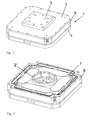
- Fig. 1 schematically a device 1 with a workpiece holder 2 is shown, wherein it can be seen that the device 1 has an upper cover plate 3 and a lower cover plate 4, between which a circumferential housing 5 is received.
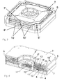
- a balance mass 7 added between the upper and lower cover plates 3, 4 and within the housing 5, as in Fig. 2 can be seen.
- the balancing mass 7 is intended to by a vibrating body 8 (see. Fig. 4 ) to decouple actively introduced inertia pulses, so that in particular resonant vibrations in a machine tool (see milling cutter 27 in Fig. 8a to 8d ), which is a tool 27 'for machining a workpiece 28 mounted on the device 1 (cf. Fig. 8a to 8d ) having, be avoided.
- the oscillating body 8 as well as the leveling compound 7 are part of a vibration device 9 accommodated in the housing 5, which is intended to cause the workpiece holder 2 to vibrate.
- a vibration device 9 accommodated in the housing 5, which is intended to cause the workpiece holder 2 to vibrate.
- the oscillating device 9 has rod-shaped piezo elements 10, 10 'as actuators, which in particular in FIG Fig. 3 can be seen.
- two rod-shaped piezo elements 10, 10 ' are provided on each side of the preferably substantially square housing 5.
- the piezoelectric elements 10 displace the oscillating body 8 (including the workpiece holder 2) into the desired oscillation, whereas the piezoelement 10 'arranged thereover displaces the leveling compound 7.
- the piezoelements 10, 10' are respectively supported on the housing 5 on the one hand Corner regions has a recess 5 ', and on the other hand at substantially centrally arranged contact projections 8' and 7 'of the oscillating body 8 and the balancing mass 7th
- the two arranged on one longitudinal side piezoelectric elements 10 and 10 ' are in this case interconnected such that they in the opposite direction of a control or regulating device 11 (see. Fig. 5 ).
- a control or regulating device 11 see. Fig. 5 .
- two so-called piezo stacks are combined in a rod-shaped piezoelectric element 10, 10'; Piezostacks of this kind are commercially available and are used, for example, for controlling injection nozzles in the automotive industry.
- piezoelectric elements 10, 10 ' which are composed of two piezo stacks, vibrations whose amplitude is up to +/- 60 microns, preferably +/- 20 microns, can be achieved.
- two piezo elements 10, 10 ' are provided, which are driven the same, as on the opposite side of the oscillating body 8 and the balancing mass 7 arranged piezo elements 10, 10 '.
- the piezoelectric elements 10, 10 'arranged substantially at a right angle thereto are controlled independently, so that the oscillating body 8 or the compensating mass 7 can execute any desired movement, for example a diagonal, or a circular movement.
- a recess 11 ' is provided in a support plate 11 of the oscillating body 8, in which a planar sliding bearing element 12', preferably made of a carbon material, is received.
- the balancing mass 7 is formed in cross-section substantially I-shaped, so that in the region between the two transverse legs, above and below a connecting leg 13 each have a receiving chamber 14 'is formed in the likewise each planar slide bearing elements 12' to form a Air bearing 12 are included.
- compressed air at a pressure of about 2 to 6 bar is introduced via a not shown in detail air supply line, so that the oscillating body 8 and the balancing mass 7 can swing substantially frictionless.
- the connecting element 2 'defined central recess can supply and discharge of compressed air into or out of the recesses 11', 14 'of the air bearing 12.
- a further actuator could be provided in this recess for the purpose of vibrational excitation in a vertical z-direction, so that not only the substantially parallel to the cover plates 3, 4 arranged piezo elements 10, 10 'in x and y with the help of the device
- any vibration eg a diagonal, a circular, sinusoidal vibration or the like, can be performed, but also in the normal direction to this level an additional vibration of the workpiece holder 2 in the z-direction can be achieved.
- the oscillating device 9 thus has four degrees of freedom - taking into account the rotation about the z-direction.
- the lower cover plate 4, the base plate 11, the housing 5 and the upper cover plate 3 are connected to each other via screws, not shown, which are screwed into the openings 16 provided for this purpose.
- the workpiece holder base is 2 'with the oscillating body 8 and the workpiece holder 2 via (not shown) screws which are screwed into the receiving openings 17, connected to each other.
- a control or regulating device 15 assigned to the device 1 via which a generator 15 'is driven, which supplies the piezoelectric elements 10, 10' with the corresponding electrical pulses, so that the oscillating device 9 with the desired frequency and the desired amplitude is vibrated.
- a generator 15 ' is driven, which supplies the piezoelectric elements 10, 10' with the corresponding electrical pulses, so that the oscillating device 9 with the desired frequency and the desired amplitude is vibrated.
- the path traveled by the balancing mass 7 and the vibrating body 8 and their acceleration is then transmitted via sensors, inter alia via a displacement sensor 15 '' (cf. Fig. 4 ), wherein via lines 15 '''the measured path or the measured acceleration is transmitted to the controller 15, so that a control loop is closed and thus an actively controlled pulse decoupling is achieved over which reliably desired resonance vibrations can be avoided.
- the control unit 15 is an operating unit 18 is switched, via which the operator can enter the desired frequency, amplitude, direction of vibration, etc.; Similarly, the control unit 15 is a numerical control 19 (NC unit) of a machine tool 27 switched on.
- Fig. 6 schematically a five-axis positioning device 20 is shown, on which the device 1 is positioned with the workpiece holder 2. Due to the five axes 21, over which the position device can be adjusted, a mechanical processing of complex 3D contours of the recorded on the workpiece holder 2 workpiece can be done.
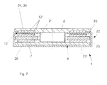
- a base body 22 is provided which Preferably, a housing 23 having a bottom surface 23 ', on which a cover plate 24 can be fastened.
- the plate-shaped workpiece holder 2 also called machine table, mounted by means of an air bearing 12;
- air bearing elements 12 'between the cover plate 24 and the workpiece holder 2 are arranged.
- a sealing element 25 between the workpiece holder 2 and the cover plate 24 is arranged to protect the air bearing 12 from the ingress of cooling lubricants and chips.
- the balance mass 7 is added, which oscillates in the opposite direction to the vibrating body 8 for momentum decoupling;
- the vibrating body 8 in this case has a base plate 26 which is connected via a preferably cylindrical connecting element 2 'with the plate-shaped workpiece holder, which is thus also part of the oscillating body 8.
- the vibrating body 8 and the balancing mass 7 are - as in connection with the principalsbespiel according to the FIGS. 1 to 5 already described in detail - connected to the oscillating device 9; ie on the oscillating body 8 and on the compensating mass 7 engage in the opposite direction vibrating piezoelectric elements 10, 10 '.
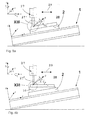
- FIGS. 8a to 8d various uses of the device 1 are shown, wherein the device is introduced in each case in a basic coordinate system (x, y, z).
- the oscillating device 9 itself has a relative coordinate system (x ', y', z ') in which the actuators oscillate.
- the device 1 can thus - as in the FIGS. 8a to 8d shown - tilted relative to the base coordinate system to be arranged; this is done by the angles ⁇ , ⁇ , ⁇ .
- the oscillatory movement then takes place in the direction of the relative coordinate system, whereas the tool 27 'of the machine tool 27 can be moved in any direction 29 in the base coordinate system, preferably along one of the coordinate main axes.
- a workpiece 28 fastened on the workpiece holder 2 can again be made by angular devices 30 along the orientation from the base coordinate system.
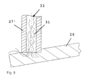
- a cooling liquid 31 (cf. Fig. 9 ), which is supplied for cooling the tool 27 'of a machine tool, such as a milling cutter 27, in the area to be machined, in the machining of hard plates 28, for example, hardened steel, ceramic materials or the like. Is vibrated. As a result, chips removed by the tool 27 'due to the vibrations of the cooling liquid 31 are transported much better.
- the cooling liquid 31 is in this case usually supplied to the area to be processed via a cooling channel 32 formed in the tool 27 '.
Landscapes
- Engineering & Computer Science (AREA)
- Mechanical Engineering (AREA)
- Auxiliary Devices For Machine Tools (AREA)
- Turning (AREA)
Description
Die Erfindung betrifft eine Vorrichtung mit einer Werkstückaufnahme zur Aufnahme eines mechanisch zu bearbeitenden Werkstücks, wobei mit der Werkstückaufnahme zumindest eine Schwingvorrichtung in Verbindung steht und die Schwingvorrichtung die Werkstückaufnahme in Schwingung versetzt, wobei die Schwingung der Werkstückaufnahme eine Frequenz aufweist, die niedriger ist als die Frequenz von Ultraschall, sowie ein Verfahren zur mechanischen Bearbeitung eines Werkstücks, wobei das Werkstück in Schwingung versetzt wird und die Frequenz der Schwingung des Werkstücks niedriger ist als die Frequenz von Ultraschall.The invention relates to a device with a workpiece holder for receiving a workpiece to be machined, wherein at least one vibrating device is in communication with the workpiece holder and the vibrating device vibrates the workpiece holder, wherein the vibration of the workpiece holder has a frequency which is lower than the frequency of ultrasound, and a method of machining a workpiece, wherein the workpiece is vibrated and the frequency of the vibration of the workpiece is lower than the frequency of ultrasound.
Im Stand der Technik sind verschiedenste Vorrichtungen und Verfahren zur sogenannten Hybridbearbeitung bzw. Ultraschall-unterstützten Bearbeitung bekannt. Hierbei wird üblicherweise ein Werkzeug im Ultraschallbereich in Schwingung versetzt, wobei als Schwingungsfrequenz vorzugsweise die Eigenfrequenz des Werkzeugs gewählt wird, sodass gewollterweise Resonanzschwingungen auftreten, durch welche insbesondere bei der spanenden Bearbeitung eines Werkstücks eine unterstützende Wirkung erzielt wird.In the prior art a variety of devices and methods for so-called hybrid processing or ultrasound-assisted processing are known. Here, usually a tool is vibrated in the ultrasonic range, wherein as the oscillation frequency, preferably the natural frequency of the tool is selected so that deliberately resonant vibrations occur, which in particular during the machining of a workpiece, a supporting effect is achieved.
Ein im Ultraschallbereich angeregtes Werkzeug ist beispielsweise aus der Publikation "
Weiters sind aus dem Stand der Technik, z.B. aus der
In der
Die
Aufgabe der vorliegenden Erfindung ist es, ein Verfahren und eine Vorrichtung zur mechanischen Bearbeitung von Werkstücken zu schaffen, mit welchem bzw. welcher verschiedenste mechanische Bearbeitungsvorgänge an einem Werkstück durch eine bzw. mit Hilfe einer schwingenden Bewegung des Werkstücks selbst durchgeführt werden können. Im Gegensatz zu bekannten Schwingvorrichtungen, bei welchen oftmals die Erzielung einer Resonanzschwingung gewünscht ist, soll bei der erfindungsgemäßen Vorrichtung eine Resonanzschwingung vermieden werden, da dies zur Beschädigung der Vorrichtung führen könnte, und demnach die Frequenz ohne Gefahr einer Beschädigung frei gewählt werden können.The object of the present invention is to provide a method and a device for the mechanical machining of workpieces with which or which various mechanical machining operations can be performed on a workpiece by means of or with the aid of a swinging movement of the workpiece itself. In contrast to known oscillating devices, in which the achievement of a resonant oscillation is often desired, a resonant oscillation should be avoided in the device according to the invention, as this could lead to damage of the device, and thus the frequency can be chosen freely without risk of damage.
Dies wird erfindungsgemäß dadurch erzielt, dass die Schwingvorrichtung einen Schwingkörper aufweist, dem eine in entgegengesetzter Richtung schwingende Ausgleichsmasse zugeordnet ist. Mit Hilfe der zum Schwingkörper der Schwingvorrichtung gegengleich schwingenden Ausgleichsmasse kann somit eine Impulsentkoppelung erzielt werden, sodass unabhängig von der Eigenfrequenz der Werkstückaufnahme bzw. der gesamten Vorrichtung jede beliebige Frequenz zur Bearbeitung des Werkstücks eingestellt werden kann.This is inventively achieved in that the oscillating device comprises a vibrating body, which is associated with a vibrating in the opposite direction balancing mass. With the help of the oscillating body of the oscillating device gegengleich oscillating balancing mass thus a pulse decoupling can be achieved, so that regardless of the natural frequency of the workpiece holder or the entire device any frequency for machining the workpiece can be adjusted.
Die erfindungsgemäße Vorrichtung, bei welcher die Werkstückaufnahme mittels einer Schwingvorrichtung in Schwingung versetzt wird, die eine niedrigere Frequenz als die Frequenz von Ultraschall aufweist, kann zu verschiedensten Zwecken eingesetzt werden.The device according to the invention, in which the workpiece holder is vibrated by means of a vibrating device, which has a lower frequency than the frequency of ultrasound, can be used for a variety of purposes.
Einerseits kann ein in der Werkstückaufnahme aufgenommenes Werkstück durch eine entsprechende Ansteuerung der Schwingvorrichtung einer helikalen oder trochoiden Bearbeitung unterzogen werden.On the one hand, a workpiece received in the workpiece holder can be subjected to a helical or a trochoidal machining by a corresponding control of the oscillating device.
Weiters kann die Vorrichtung auch zur Hybridbearbeitung, d.h. dem schwingungsunterstützten mechanischen Bearbeiten von in der Werkstückaufnahme befestigten Werkstücken, eingesetzt werden. Unter mechanischen Bearbeitungen im Zusammenhang mit der vorliegenden Erfindung sind insbesondere jede spanende Bearbeitung mit geometrisch bestimmter oder geometrisch unbestimmter Schneide zu verstehen; dies umfasst insbesondere Drehen, Bohren, Fräsen, Reiben sowie Schleifen, Honen, Läppen und Polieren.Furthermore, the device can also be used for hybrid processing, i. the vibration-assisted mechanical machining of workpieces mounted in the workpiece holder, are used. Mechanical operations in connection with the present invention are to be understood as meaning, in particular, any machining with geometrically defined or geometrically indefinite cutting edges; This includes in particular turning, drilling, milling, reaming and grinding, honing, lapping and polishing.
Sofern die Frequenz entsprechend niedrig gewählt wird, kann mit Hilfe der Schwingvorrichtung die Vorrichtung selbstverständlich auch zur Positionierung des in der Werkstückaufnahme angeordneten Werkstücks verwendet werden.If the frequency is selected to be correspondingly low, the device can of course also be used for positioning the workpiece arranged in the workpiece holder with the aid of the oscillating device.
Insbesondere kann die Vorrichtung - ähnlich bekannten Vorrichtungen, bei welchen jedoch das Werkzeug im Ultraschallbereich angeregt wird - zur Unterstützung der mechanischen Bearbeitung von schwierig zu bearbeitenden Materialien, d.h. insbesondere harten und/oder spröden Materialien, wie z.B. Keramik, Glas, verschiedenste Silizium-Werkstoffe, wie Siliziumnitrid oder Siliziumoxid, aber auch gehärtetem Stahl oder dergl, eingesetzt werden. Für die verschiedensten Anwendungen hat es sich als günstig herausgestellt, wenn die Frequenz der Schwingung der Werkstückaufnahme unter 10 kHz, vorzugsweise unter 5 kHz, insbesondere unter 1 kHz, besonders bevorzugt zwischen 500 Hz und 50 Hz beträgt.In particular, the device may be similar to known devices in which, however, the tool is excited in the ultrasonic range to assist in the machining of difficult-to-machine materials, i. especially hard and / or brittle materials, e.g. Ceramics, glass, a variety of silicon materials such as silicon nitride or silicon oxide, but also hardened steel or the like can be used. For a variety of applications, it has proved to be advantageous if the frequency of the vibration of the workpiece holder is less than 10 kHz, preferably less than 5 kHz, in particular less than 1 kHz, more preferably between 500 Hz and 50 Hz.
Zur Kompensation der Trägheitskräfte des Schwingkörpers, kann die Ausgleichsmasse eine zum Schwingkörper idente Masse aufweisen; in diesem Fall wird die Ausgleichsmasse mit der gleichen Frequenz und der gleichen Beschleunigung wie der Schwingkörper, jedoch mit entgegengesetzter Bewegungsrichtung in Schwingung versetzt. Wenn Schwingkörper und Ausgleichsmasse nicht die gleiche Masse aufweisen, kann ein kompensierender Trägheitseffekt über eine Anpassung der Beschleunigung erzielt werden. Sofern die Ausgleichsmasse eine geringere Masse als der Schwingkörper aufweist, ist es zum Impulsausgleich demzufolge vorteilhaft, wenn die Ausgleichsmasse mit der gleichen Frequenz wie und einer größeren Amplitude als der Schwingkörper schwingt. Demzufolge schwingt die Ausgleichsmasse mit der gleichen Frequenz wie der Schwingkörper, weist jedoch eine höhere Beschleunigung auf und legt somit bei gleicher Frequenz einen größeren Weg zurück.To compensate for the inertial forces of the vibrating body, the balancing mass may have an identical to the vibrating body mass; In this case, the balancing mass is vibrated at the same frequency and the same acceleration as the vibrating body, but in the opposite direction of movement. If the vibrating body and balancing mass do not have the same mass, a compensating inertia effect can be achieved by adjusting the acceleration. If the balancing mass has a lower mass than the oscillating body, it is therefore advantageous for pulse compensation if the compensating mass oscillates at the same frequency as and a larger amplitude than the vibrating body. Consequently, the balancing weight oscillates at the same frequency as the Oscillating, but has a higher acceleration and thus sets at the same frequency a greater way back.
Aufgrund der konstruktiven Gegebenheiten hat sich insbesondere als vorteilhaft herausgestellt, wenn das Verhältnis der Amplituden der Schwingungen der Ausgleichsmasse und des Schwingkörpers zwischen [1]:[5] und [5]:[1], im Wesentlichen [1]:[1], beträgt.Due to the structural conditions, it has proven particularly advantageous if the ratio of the amplitudes of the oscillations of the balancing mass and the vibrating body between [1]: [5] and [5]: [1], essentially [1]: [1] is.
Um Schwingungen der Werkstückaufnahme im gewünschten Frequenzbereich auf einfache und zuverlässige Weise zu erzielen, ist es von Vorteil, wenn die Schwingvorrichtung zumindest ein Piezoelement aufweist.In order to achieve vibrations of the workpiece holder in the desired frequency range in a simple and reliable manner, it is advantageous if the oscillating device has at least one piezoelectric element.
Um auf einfache Art und Weise jede beliebige Art der Schwingung des Schwingkörpers in einer Ebene erzielen zu können, d.h. z.B. eine kreisende, diagonale, etc. Form der Schwingbewegung, ist es von Vorteil, wenn zur Verschiebung des Schwingkörpers in einer Ebene zumindest zwei, vorzugsweise senkrecht zueinander angeordnete Bewegungsrichtungen aufweisende, Piezoelemente vorgesehen sind. Hinsichtlich einer konstruktiv einfachen Ausgestaltung der Vorrichtung, bei welcher mittels der Piezoelemente die gewünschten Amplituden erzielt werden können, ist es günstig, wenn zur Verschiebung des Schwingkörpers in eine Richtung dem Schwingkörper zumindest jeweils zwei Piezoelemente zugeordnet sind. Hierbei können sich die Piezoelemente jeweils auf einfache Weise einerseits außenseitig an einem die Schwingvorrichtung umgebenden Gehäuse und andererseits an einem vorzugsweise im Wesentlichen mittig angeordneten Anlagevorsprung am Schwingkörper abstützten.In order to be able to achieve in a simple manner any type of vibration of the vibrating body in one plane, i. e.g. a circular, diagonal, etc. shape of the oscillating movement, it is advantageous if at least two, preferably arranged perpendicular to each other movement directions, piezoelectric elements are provided for displacement of the oscillating body in a plane. With regard to a structurally simple embodiment of the device in which the desired amplitudes can be achieved by means of the piezoelectric elements, it is favorable if, for the displacement of the oscillating body in one direction, at least two piezoelements are assigned to the oscillating body. In this case, the piezoelectric elements can each be supported in a simple manner on the one hand on the outside on a housing surrounding the oscillating device and on the other hand on a preferably substantially centrally arranged abutment projection on the oscillating body.
Zur Erzielung der gewünschten Trägheitsimpulsentkopplung ist es hinsichtlich einer einfachen Regelung von Vorteil, wenn an der Ausgleichsmasse im Wesentlichen die gleiche Art und Anzahl an Piezoelementen angreift wie an dem Schwingkörper.In order to achieve the desired inertial pulse decoupling, it is advantageous in terms of simple control if substantially the same type and number of piezo elements act on the balancing mass as on the vibrating body.
Um die gewünschte Impulsentkoppelung der Schwingvorrichtung zu erzielen, ist es von Vorteil, wenn eine Steuer- bzw. Regelvorrichtung vorgesehen ist, mit welcher gegengleiche Bewegungen der Piezoelemente, welche dem Schwingkörper zugeordnet sind, und jener Piezoelemente, die der Ausgleichsmasse zugeordnet sind, gesteuert bzw. geregelt werden. Hierbei ist es von Vorteil, wenn dem Schwingkörper und der Ausgleichsmasse Weg- und/oder Beschleunigungssensoren zugeordnet sind, deren Messwerte als Ist-Größen der Steuer- bzw. Regelvorrichtung zugeführt werden.In order to achieve the desired momentum decoupling of the oscillating device, it is advantageous if a control or regulating device is provided, with which opposite movements of the piezo elements, which are associated with the oscillating body, and those piezo elements, which are associated with the balancing mass, controlled or be managed. It is advantageous if associated with the oscillating body and the balancing mass displacement and / or acceleration sensors whose measured values are supplied as actual variables of the control or regulating device.
Um Reibungsverluste bei den Schwingungsbewegungen des Schwingkörpers und der Ausgleichsmasse möglichst gering zu halten, ist es günstig, wenn der Schwingkörper und/oder die Ausgleichsmasse auf zumindest einem Luftlager gelagert sind.In order to minimize friction losses in the vibration movements of the vibrating body and the balancing mass, it is advantageous if the vibrating body and / or the balancing mass are mounted on at least one air bearing.
Um auf das Werkstück bzw. die Werkstückaufnahme eingeleitete Drehmomente zweckmäßig aufnehmen zu können, ist es günstig, wenn eine plattenförmige Werkstückaufnahme vorgesehen ist, die auf einer Deckplatte eines Grundkörpers, vorzugsweise mittels eines Luftlagers, gelagert ist. Somit ist die plattentförmige Werkstückaufnahme, auch Maschinentisch genannt, direkt auf einer benachbarten Deckplatte gelagert, sodass etwaigen Kippkräften, die auf die Werkstückaufnahme wirken, kein Hebel geboten wird.In order to be able to absorb torques introduced on the workpiece or the workpiece holder, it is advantageous if a plate-shaped workpiece holder is provided, which is mounted on a cover plate of a base body, preferably by means of an air bearing. Thus, the plate-shaped workpiece holder, also called machine table, mounted directly on an adjacent cover plate, so any tilting forces acting on the workpiece holder, no leverage is offered.
Um die aus den Bewegungskräften resultierenden Momente weiter zu reduzieren, ist es günstig, wenn die plattenförmige Werkstückaufnahme mit einer Gegenplatte fest verbunden ist, wobei zwischen der plattenförmigen Werkstückaufnahme und der Gegenplatte die Ausgleichmasse angeordnet ist.In order to further reduce the moments resulting from the movement forces, it is expedient for the plate-shaped workpiece holder to be fixedly connected to a counterplate, wherein the compensating mass is arranged between the plate-shaped workpiece holder and the counterplate.
Hinsichtlich der Verwendung bei der mechanischen Bearbeitung von Werkstücken ist es zwecks Ausrichtung der Werkstückaufnahme in verschiedensten Orientierungen von Vorteil, wenn die Vorrichtung auf einer Positioniervorrichtung angeordnet ist. Hierbei ist es insbesondere günstig, wenn bis zu fünf Achsen der Positioniervorrichtung verstellbar sind, da hierdurch eine beliebige Ausrichtung der Werkstückaufnahme in alle erdenklichen Richtungen möglich ist.With regard to the use in the machining of workpieces, it is advantageous for aligning the workpiece holder in various orientations when the device is arranged on a positioning device. It is particularly advantageous if up to five axes of the positioning device can be adjusted, as this arbitrary alignment of the workpiece holder in all imaginable directions is possible.
Wenn zumindest eine Schwingungsrichtung der Schwingvorrichtung abweichend von einer Bewegungsrichtung eines spanenden Werkzeugs, vorzugsweise Fräswerkzeugs, ist, kann die Vorrichtung beispielsweise nur in einer Ebene bewegt werden, zugleich wird jedoch aufgrund der abweichenden Schwingungsrichtung gegenüber der Bewegung des Werkzeugs eine räumliche Veränderung gegenüber dem Werkzeug erzielt.If at least one direction of oscillation of the oscillating device deviates from a direction of movement of a cutting tool, preferably a milling tool, the device can, for example, only be moved in one plane, but at the same time a spatial change relative to the tool is achieved due to the differing direction of oscillation with respect to the movement of the tool.
Tests haben gezeigt, dass es insbesondere vorteilhaft ist, wenn ein mittels einer Kühlflüssigkeit gekühltes zur spanenden Bearbeitung vorgesehenes Werkzeug, vorzugsweise Fräswerkzeug, vorgesehen ist. Dabei hat sich herausgestellt, dass aufgrund der Schwingungen des in bzw. auf der Werkstückaufnahme aufgenommenen Werkstücks ein deutlich verbessertes Spülverhalten der mit Spänen versetzten Kühlflüssigkeit erzielt wird, sodass es zu einem deutlich verbesserten Abtransport des von dem Werkstück bereits abgetragenen Materials kommt. Tests wurden hierbei insbesondere im Zusammenhang mit plattenförmigen, keramischen Materialien durchgeführt.Tests have shown that it is particularly advantageous if a tool, preferably a milling tool, provided for machining, cooled by means of a coolant, is provided. It has been found that due to the vibrations of the workpiece received in or on the workpiece holder, a significantly improved flushing behavior of the chips mixed with chips is achieved, resulting in a significantly improved removal of the material already removed from the workpiece. Tests were in this case carried out in particular in connection with plate-shaped, ceramic materials.
Das Verfahren der eingangs angeführten Art ist dadurch gekennzeichnet, dass zur Vermeidung von Resonanzschwingungen des Werkstücks und der Werkzeugmaschine der zur Erzeugung der Schwingung eingeleitete Impuls mittels einer in entgegengesetzter Richtung schwingenden Ausgleichsmasse aktiv entkoppelt wird, wobei vorzugsweise die Frequenz der Schwingung des Werkstücks unter 10 kHz, vorzugsweise unter 5 kHz, insbesondere unter 1 kHz, besonders bevorzugt zwischen 500 Hz und 50 Hz beträgt. Die im Zusammenhang mit dem erfindungsgemäßen Verfahren erzielten vorteilhaften Effekte sind bereits im Zusammenhang mit der korrespondierenden Vorrichtung erläutert, sodass zwecks Vermeidung von Wiederholungen hierauf verwiesen wird.The method of the initially cited type is characterized in that, in order to avoid resonance vibrations of the workpiece and the machine tool, the pulse introduced to generate the oscillation is actively decoupled by means of a balancing mass oscillating in the opposite direction, preferably the frequency of the oscillation of the workpiece being less than 10 kHz, preferably below 5 kHz, in particular below 1 kHz, more preferably between 500 Hz and 50 Hz. The advantageous effects achieved in connection with the method according to the invention are already explained in connection with the corresponding device, so that reference is made to avoid repetition.
Wenn die Ausgleichsmasse eine geringere Masse als der Schwingkörper aufweist, schwingt die Ausgleichsmasse zur Impulsentkopplung vorteilhafterweise mit der gleichen Frequenz und einer größeren Amplitude als der Schwingkörper. Die Impulsentkopplung ist hierbei vorteilhafterweise aktiv geregelt, wie bereits im Zusammenhang mit der erfindungsgemäßen Vorrichtung beschrieben.If the balancing mass has a lower mass than the vibrating body, the balancing mass for impulse decoupling advantageously oscillates at the same frequency and a greater amplitude than the vibrating body. The impulse decoupling here is advantageously actively regulated, as already described in connection with the device according to the invention.
Die Erfindung wird nachstehend anhand von in den Zeichnungen dargestellten bevorzugten Ausführungsbeispielen, auf die sie jedoch nicht beschränkt sein soll, noch näher erläutert. Im Einzelnen zeigen in den Zeichnungen:
-
Fig. 1 eine perspektivische Ansicht der Vorrichtung mit einer Werkstückaufnahme; -
Fig. 2 eine perspektivische Ansicht der Vorrichtung gemäßFig. 1 mit abgenommener Werkstückaufnahme und einer abgenommenen Deckplatte; -
Fig. 3 eine perspektivische Ansicht gemäßFig. 2 mit einer teilweise aufgebrochenen Seitenwand eines Gehäuses; -
Fig. 4 eine perspektivische Schnittansicht der Vorrichtung gemäß denFig. 1 bis 3 ; -
Fig. 5 eine schematische Ansicht eines Regelkreises zur Regelung einer Impulsentkoppelung; -
Fig. 6 eine schematische Ansicht einer Positioniervorrichtung, auf welcher eine erfindungsgemäße Vorrichtung angeordnet ist; -
Fig. 7 eine Schnittansicht eines alternativen Aufbaus der erfindungsgemäßen Vorrichtung; -
Fig. 8a bis 8d schematische Seitenansichten eines auf der Vorrichtung aufgenommenen Werkstücks, welches über eine Fräsvorrichtung bearbeitet wird; und -
Fig. 9 eine schematische Detailansicht gemäß Detail VIII inFig. 8a .
-
Fig. 1 a perspective view of the device with a workpiece holder; -
Fig. 2 a perspective view of the device according toFig. 1 with removed workpiece holder and a removed cover plate; -
Fig. 3 a perspective view according toFig. 2 with a partially broken sidewall of a housing; -
Fig. 4 a sectional perspective view of the device according to theFig. 1 to 3 ; -
Fig. 5 a schematic view of a control circuit for controlling a pulse decoupling; -
Fig. 6 a schematic view of a positioning device on which a device according to the invention is arranged; -
Fig. 7 a sectional view of an alternative construction of the device according to the invention; -
Fig. 8a to 8d schematic side views of a recorded on the device workpiece, which is processed via a milling device; and -
Fig. 9 a schematic detail view according to detail VIII inFig. 8a ,
In
Zwischen der oberen und unteren Deckplatte 3, 4 und innerhalb des Gehäuses 5 ist, wie in
Der Schwingkörper 8 wie auch die Ausgleichsmasse 7 sind Teil einer in dem Gehäuse 5 aufgenommenen Schwingvorrichtung 9, die dazu vorgesehen ist, die Werkstückaufnahme 2 in Schwingung zu versetzen. Hierzu ist die in
Die Schwingvorrichtung 9 weist als Aktuatoren stabförmige Piezoelemente 10, 10' auf, die insbesondere in
Die Piezoelemente 10 versetzen hierbei den Schwingkörper 8 (einschließlich der Werkstückaufnahme 2) in die gewünschte Schwingung, die darüber angeordneten Piezoelement 10' hingegen die Ausgleichsmasse 7. Die Piezoelemente 10, 10' stützen sich jeweils einerseits an dem Gehäuse 5 ab, welches hiefür in den Eckbereichen eine Einbuchtung 5' aufweist, und andererseits an im Wesentlichen mittig angeordneten Anlagevorsprüngen 8' bzw. 7' des Schwingkörpers 8 bzw. der Ausgleichsmasse 7.The
Die beiden an einer Längsseite angeordneten Piezoelemente 10 bzw. 10' sind hierbei derart zusammengeschaltet, dass sie in entgegengesetzter Richtung von einer Steuer- bzw. Regelvorrichtung 11 (vgl.
Zur Ausbildung von Luftlagern 12 ist in einer Auflageplatte 11 des Schwingkörpers 8 eine Ausnehmung 11' vorgesehen, in welcher ein planares Gleitlager-Element 12', vorzugsweise aus einem Karbon-Material, aufgenommen ist. Die Ausgleichsmasse 7 ist im Querschnitt im Wesentlichen I-förmig ausgebildet, sodass in dem Bereich zwischen den beiden Querschenkeln, ober- und unterhalb eines Verbindungsschenkels 13 jeweils eine Aufnahmekammer 14' ausgebildet ist, in der ebenfalls jeweils planare Gleitlager-Elemente 12' zur Ausbildung eines Luftlagers 12 aufgenommen sind. In den Aufnahmekammern 11' bzw. 14' wird über eine nicht näher gezeigte Luftzufuhrleitung Druckluft mit einem Druck von ca. 2 bis 6 bar eingeleitet, sodass der Schwingkörper 8 und die Ausgleichsmasse 7 im Wesentlichen reibungsfrei schwingen können.For the formation of
In einer von dem Verbindungselement 2' definierten mittigen Ausnehmung kann eine Zu- und Abfuhr von Druckluft in die bzw. aus den Ausnehmungen 11', 14' der Luftlager 12 erfolgen. Zudem könnte in dieser Ausnehmung auch noch ein weiterer Aktuator zwecks Schwingungsanregung in einer vertikalen z-Richtung vorgesehen sein, sodass mit Hilfe der Vorrichtung nicht nur über die im Wesentlichen parallel zu den Deckplatten 3, 4 angeordneten Piezoelemente 10, 10' in x- und y-Richtung jede beliebige Schwingung, z.B. eine diagonale, eine kreisförmige, sinusförmige Schwingung oder dergl, durchgeführt werden kann, sondern zudem auch in Normalrichtung auf diese Ebene eine zusätzliche Schwingung der Werkstückaufnahme 2 in z-Richtung erzielt werden kann. Die Schwingvorrichtung 9 weist somit vier Freiheitsgrade auf - mit Berücksichtigung der Rotation um die z-Richtung.In one of the connecting element 2 'defined central recess can supply and discharge of compressed air into or out of the recesses 11', 14 'of the
Wie der Schnittdarstellung in
In
Der von der Ausgleichsmasse 7 und dem Schwingkörper 8 zurückgelegte Weg und deren Beschleunigung wird sodann über Sensoren, u.a. über einen Weggeber 15'' (vgl.
In
In
In dem Grundkörper 23 ist die Ausgleichsmasse 7 aufgenommen, die zur Impulsentkoppelung in entgegengesetzter Richtung zum Schwingkörper 8 schwingt; der Schwingkörper 8 weist hierbei eine Grundplatte 26 auf, die über ein vorzugsweise zylindrisches Verbindungselement 2' mit der plattenförmigen Werkstückaufnahme verbunden ist, die somit ebenfalls Teil des Schwingkörpers 8 ist. Der Schwingkörper 8 sowie die Ausgleichsmasse 7 sind - wie im Zusammenhang mit dem Ausführungsbespiel gemäß den
In den
Insbesondere hat sich hierbei als vorteilhaft herausgestellt, dass eine Kühlflüssigkeit 31 (vgl.
Claims (17)
- A device (1) with a workpiece-receiving portion (2) for receiving a workpiece (28) to be mechanically machined, wherein at least one vibrating device (9) is connected to the workpiece-receiving portion (2), and the vibrating device (9) causes the workpiece-receiving portion (2) to vibrate, wherein the vibration of the workpiece-receiving portion (2) has a frequency that is lower than the frequency of ultrasound, characterised in that the vibrating device (9) has a vibrating body (8) to which a compensating mass (7) vibrating in the opposite direction is associated.
- The device according to claim 1, characterised in that the frequency of the vibration of the workpiece-receiving portion (2) is below 10 kHz, preferably below 5 kHz, in particular below 1 kHz, especially preferably between 500 Hz and 50 Hz.
- The device according to claim 1 or 2, characterised in that the compensating mass (7) vibrates at the same frequency as and with a higher amplitude than the vibrating body (8).
- The device according to any one of claims 1 to 3, characterised in that the vibrating device (9) has at least one piezo element (10, 10').
- The device according to claim 4, characterised in that for moving the vibrating body (8) in a plane, at least two piezo elements (10) having directions of movement that are preferably arranged vertically to one another are provided.
- The device according to claim 4 or 5, characterised in that substantially the same type and number of piezo elements (10') engage the compensating mass (7) and the vibrating body (8).
- The device according to any one of claims 4 to 6, characterised in that a control and/or regulating device (11) is provided for controlling and/or regulating opposite movements of the piezo elements (10) associated to the vibrating body (8) and the piezo elements (10') associated to the compensating mass (7).
- The device according to claim 7, characterised in that distance and/or acceleration sensors are associated with the vibrating body (8) and the compensating mass (7), with the values measured being supplied to the control and/or regulating device (11) as actual values.
- The device according to any one of claims 1 to 8, characterised in that the vibrating body (8) and/or the compensating mass (7) are supported on at least one air bearing (12).
- The device according to any one of claims 1 to 9, characterised in that a plate-shaped workpiece-receiving portion (2) that is supported on a cover plate (24) of a base body, preferably by an air bearing (12), is provided.
- The device according to claim 10, characterised in that the plate-shaped workpiece-receiving portion (2) is firmly connected to a counter plate (26), with the compensating mass (7) being arranged between the plate-shaped workpiece-receiving portion (2) and the counter plate.
- The device according to any one of claims 1 to 11, characterised in that the device (1) is arranged on a positioning device (20).
- The device according to claim 12, characterised in that up to five axes of the positioning device (20) are adjustable.
- The device (1) according to any one of claims 1 to 13, characterised in that at least one vibrating direction (x', y', z') of the vibrating device (9) deviates from a direction of movement (29) of a chip-removing tool (27'), preferably a milling tool.
- The device (1) according to any one of claims 1 to 14, characterised in that a tool (27'), preferably a milling tool, provided for chip-removing machining is provided, which is cooled by a cooling liquid (31) and/or a cooling grease.
- A method for mechanically machining a workpiece (28), wherein the workpiece (28) is caused to vibrate and the frequency of the vibration of the workpiece (28) is lower than the frequency of ultrasound, characterised in that the momentum introduced into the workpiece (28) by the vibration is actively decoupled by means of a compensating mass (7) vibrating in the opposite direction.
- The method according to claim 16, characterised in that the frequency of the vibration of the workpiece (28) is below 10 kHz, preferably below 5 kHz, in particular below 1 kHz, especially preferably between 500 Hz and 50 Hz.
Applications Claiming Priority (2)
| Application Number | Priority Date | Filing Date | Title |
|---|---|---|---|
| ATA706/2011A AT511551B1 (en) | 2011-05-18 | 2011-05-18 | DEVICE AND METHOD FOR MECHANICAL MACHINING OF A WORKPIECE |
| PCT/AT2012/000137 WO2012167288A1 (en) | 2011-05-18 | 2012-05-18 | Vibrating device with workpiece receiving portion and compensating mass |
Publications (2)
| Publication Number | Publication Date |
|---|---|
| EP2709796A1 EP2709796A1 (en) | 2014-03-26 |
| EP2709796B1 true EP2709796B1 (en) | 2014-09-17 |
Family
ID=46207816
Family Applications (1)
| Application Number | Title | Priority Date | Filing Date |
|---|---|---|---|
| EP12762520.0A Not-in-force EP2709796B1 (en) | 2011-05-18 | 2012-05-18 | Oscillating device with workpiece holder and compensating mass, and method |
Country Status (5)
| Country | Link |
|---|---|
| US (1) | US9346139B2 (en) |
| EP (1) | EP2709796B1 (en) |
| CN (1) | CN103547412B (en) |
| AT (1) | AT511551B1 (en) |
| WO (1) | WO2012167288A1 (en) |
Cited By (1)
| Publication number | Priority date | Publication date | Assignee | Title |
|---|---|---|---|---|
| DE102015101167A1 (en) | 2015-01-27 | 2016-07-28 | Technische Universität Wien | spindle assembly |
Families Citing this family (9)
| Publication number | Priority date | Publication date | Assignee | Title |
|---|---|---|---|---|
| WO2014033905A1 (en) * | 2012-08-31 | 2014-03-06 | Minami Hironori | Method for processing toughened glass and processing device for toughened glass |
| DE102013110728B4 (en) * | 2013-09-27 | 2021-08-19 | Ev Group E. Thallner Gmbh | System and method for machining a workpiece |
| US9517512B2 (en) * | 2014-09-26 | 2016-12-13 | Chuan Liang Industrial Co., Ltd. | Ultrasonic positioning device for five-axis machine |
| EP3536451A1 (en) * | 2018-03-07 | 2019-09-11 | Horst Knäbel | Method and apparatus for improving the concentricity and stress-tolerance of conical joint made up of an annularly closed container and a compressible and expandable sleeve |
| CN108705329B (en) * | 2018-08-22 | 2023-08-22 | 金陵科技学院 | Precision workbench based on two-degree-of-freedom piezoelectric actuator and corresponding piezoelectric actuator |
| DE102018127275B3 (en) * | 2018-10-31 | 2020-03-12 | Asm Assembly Systems Gmbh & Co. Kg | Component feeder and method for providing isolated components by means of vibration, placement system |
| CN109894965B (en) * | 2019-04-11 | 2023-12-01 | 哈尔滨汽轮机厂有限责任公司 | Auxiliary device and grinding method for grinding annular workpiece by numerical control milling machine |
| CN111215644B (en) * | 2020-02-17 | 2021-05-04 | 中国工程物理研究院机械制造工艺研究所 | Ultrasonic vibration assisted cutting feedback signal detection and compensation device and method and application |
| CN112405033B (en) * | 2020-10-15 | 2022-06-14 | 渤海造船厂集团有限公司 | Adjustable platform for machining gasket and method thereof |
Family Cites Families (14)
| Publication number | Priority date | Publication date | Assignee | Title |
|---|---|---|---|---|
| JPH0722876B2 (en) * | 1987-06-24 | 1995-03-15 | 新技術事業団 | Work table device for grinding |
| DE4113667A1 (en) * | 1991-04-26 | 1992-11-05 | Fraunhofer Ges Forschung | Piezoelectric positioning drive for machine tools - uses copper@ heat sink and Peltier-effect modules to reduce operating temp. |
| US6241435B1 (en) * | 1998-03-25 | 2001-06-05 | Vought Aircraft Industries, Inc. | Universal adaptive machining chatter control fixture |
| US6906786B2 (en) | 2002-06-07 | 2005-06-14 | Asml Netherlands B.V. | Lithographic apparatus and device manufacturing method |
| DE10307308B4 (en) * | 2003-02-20 | 2006-11-30 | Siemens Ag | Device for the linear method of a useful mass |
| DK176725B1 (en) * | 2003-07-04 | 2009-05-04 | Kvm Industrimaskiner As | Method for making a vibration table for concrete casting machines and a vibration loaf made according to the method |
| JP4396518B2 (en) * | 2004-12-28 | 2010-01-13 | トヨタ自動車株式会社 | Attitude control device and precision processing device |
| US7508116B2 (en) * | 2005-09-07 | 2009-03-24 | Panasonic Corporation | Method and apparatus for vibration machining with two independent axes |
| DE102005056603B4 (en) * | 2005-11-28 | 2019-02-21 | Siemens Aktiengesellschaft | Method for reducing vibrations occurring during a machining process of a machine element and / or a workpiece |
| DE102005057175B4 (en) * | 2005-11-30 | 2009-03-26 | Siemens Ag | Method for reducing vibrations of a machine element and / or a workpiece |
| CN101104244A (en) | 2006-07-10 | 2008-01-16 | 宁波工程学院 | Ultrasonic magnetic-granular composite milling method and its device |
| DE102006049867B4 (en) * | 2006-10-23 | 2021-09-16 | Siemens Aktiengesellschaft | Machine tool and method for suppressing chatter vibrations |
| US7687975B2 (en) * | 2007-03-27 | 2010-03-30 | Panasonic Corporation | Vibration assisted machining system with stacked actuators |
| DE102010055288A1 (en) * | 2010-12-21 | 2012-06-21 | Ev Group Gmbh | Device for machining a workpiece |
-
2011
- 2011-05-18 AT ATA706/2011A patent/AT511551B1/en not_active IP Right Cessation
-
2012
- 2012-05-18 EP EP12762520.0A patent/EP2709796B1/en not_active Not-in-force
- 2012-05-18 CN CN201280023898.3A patent/CN103547412B/en not_active Expired - Fee Related
- 2012-05-18 US US14/118,440 patent/US9346139B2/en active Active
- 2012-05-18 WO PCT/AT2012/000137 patent/WO2012167288A1/en active Application Filing
Cited By (2)
| Publication number | Priority date | Publication date | Assignee | Title |
|---|---|---|---|---|
| DE102015101167A1 (en) | 2015-01-27 | 2016-07-28 | Technische Universität Wien | spindle assembly |
| US11097391B2 (en) | 2015-01-27 | 2021-08-24 | Technische Universität Wien | Spindle arrangement |
Also Published As
| Publication number | Publication date |
|---|---|
| AT511551B1 (en) | 2013-10-15 |
| CN103547412A (en) | 2014-01-29 |
| WO2012167288A1 (en) | 2012-12-13 |
| EP2709796A1 (en) | 2014-03-26 |
| AT511551A1 (en) | 2012-12-15 |
| US20140093322A1 (en) | 2014-04-03 |
| US9346139B2 (en) | 2016-05-24 |
| CN103547412B (en) | 2016-05-04 |
Similar Documents
| Publication | Publication Date | Title |
|---|---|---|
| EP2709796B1 (en) | Oscillating device with workpiece holder and compensating mass, and method | |
| WO2012084779A1 (en) | System having two oscillation components for machining a workpiece | |
| CN102120214B (en) | Three-degree-of-freedom series and parallel connection vibrating screen | |
| DE102010048636B4 (en) | Machine tool and method for machining a workpiece with a tool | |
| EP1247613B1 (en) | Drive system for a load in a machine, with a reaction part | |
| WO1999048191A1 (en) | Impulse-decoupled direct drive mechanism | |
| DE102010048638A1 (en) | Machine tool, workpiece machining process | |
| EP3250340B1 (en) | Spindle arrangement | |
| EP3210718A2 (en) | Processing unit of a machine tool and machine tool with such a processing unit | |
| WO2012052525A1 (en) | Device for the highly dynamic movement of the working point of a beam | |
| WO2011023185A2 (en) | Device for compensating torque resulting from the acceleration of redundant additional axes in measuring machines and machine tools, by means of a plurality of compensation masses which move in a coordinated linear manner | |
| EP2374574A1 (en) | High speed honing machine | |
| EP3509791B1 (en) | Vibration polishing device | |
| AT513094B1 (en) | Device, in particular chip tool | |
| DE102005038108A1 (en) | Surface polishing assembly for e.g. glass, metal, paint, previous stones has two oscillating frames operating in a predefined phase sequence | |
| DE19945584A1 (en) | Multi-dimensional drive for work machines | |
| DE102011003009A1 (en) | Processing machine for producing tear line in airbag cover, has fourth linear guide unit that is attached with tool head and connected to control unit for controlling movement of tool along specific axis | |
| EP4159331B1 (en) | Cleaning device with oscillating object holder | |
| DE10161243B4 (en) | Microstructuring with ultrasound-assisted grinding | |
| EP4334062A1 (en) | Method and device for removing supporting structures from an object | |
| DE102021201170A1 (en) | Method for avoiding resonance damage during cleaning of an at least partially additively manufactured component, and cleaning device | |
| DE2659975C2 (en) | Method and device for cutting surfaces such as metal surfaces, surfaces of structures or the like. | |
| DE102012105948A1 (en) | Oscillation platform for manufacturing system for machining or abrasive machining of workpiece, has tool arranged on swinging receiving plate that is arranged on support plate by resilient intermediate part | |
| CH655883A5 (en) | Method of producing tool electrodes for electrical discharge machining and apparatus for carrying it out | |
| WO2015149754A1 (en) | Computer-controlled machine tool for producing small workpieces |
Legal Events
| Date | Code | Title | Description |
|---|---|---|---|
| PUAI | Public reference made under article 153(3) epc to a published international application that has entered the european phase |
Free format text: ORIGINAL CODE: 0009012 |
|
| 17P | Request for examination filed |
Effective date: 20131118 |
|
| AK | Designated contracting states |
Kind code of ref document: A1 Designated state(s): AL AT BE BG CH CY CZ DE DK EE ES FI FR GB GR HR HU IE IS IT LI LT LU LV MC MK MT NL NO PL PT RO RS SE SI SK SM TR |
|
| GRAP | Despatch of communication of intention to grant a patent |
Free format text: ORIGINAL CODE: EPIDOSNIGR1 |
|
| INTG | Intention to grant announced |
Effective date: 20140422 |
|
| GRAS | Grant fee paid |
Free format text: ORIGINAL CODE: EPIDOSNIGR3 |
|
| GRAA | (expected) grant |
Free format text: ORIGINAL CODE: 0009210 |
|
| DAX | Request for extension of the european patent (deleted) | ||
| AK | Designated contracting states |
Kind code of ref document: B1 Designated state(s): AL AT BE BG CH CY CZ DE DK EE ES FI FR GB GR HR HU IE IS IT LI LT LU LV MC MK MT NL NO PL PT RO RS SE SI SK SM TR |
|
| REG | Reference to a national code |
Ref country code: GB Ref legal event code: FG4D Free format text: NOT ENGLISH |
|
| REG | Reference to a national code |
Ref country code: CH Ref legal event code: EP |
|
| REG | Reference to a national code |
Ref country code: IE Ref legal event code: FG4D Free format text: LANGUAGE OF EP DOCUMENT: GERMAN |
|
| REG | Reference to a national code |
Ref country code: AT Ref legal event code: REF Ref document number: 687455 Country of ref document: AT Kind code of ref document: T Effective date: 20141015 Ref country code: CH Ref legal event code: NV Representative=s name: RENTSCH PARTNER AG, CH |
|
| REG | Reference to a national code |
Ref country code: DE Ref legal event code: R096 Ref document number: 502012001285 Country of ref document: DE Effective date: 20141106 |
|
| PG25 | Lapsed in a contracting state [announced via postgrant information from national office to epo] |
Ref country code: FI Free format text: LAPSE BECAUSE OF FAILURE TO SUBMIT A TRANSLATION OF THE DESCRIPTION OR TO PAY THE FEE WITHIN THE PRESCRIBED TIME-LIMIT Effective date: 20140917 Ref country code: NO Free format text: LAPSE BECAUSE OF FAILURE TO SUBMIT A TRANSLATION OF THE DESCRIPTION OR TO PAY THE FEE WITHIN THE PRESCRIBED TIME-LIMIT Effective date: 20141217 Ref country code: GR Free format text: LAPSE BECAUSE OF FAILURE TO SUBMIT A TRANSLATION OF THE DESCRIPTION OR TO PAY THE FEE WITHIN THE PRESCRIBED TIME-LIMIT Effective date: 20141218 Ref country code: LT Free format text: LAPSE BECAUSE OF FAILURE TO SUBMIT A TRANSLATION OF THE DESCRIPTION OR TO PAY THE FEE WITHIN THE PRESCRIBED TIME-LIMIT Effective date: 20140917 Ref country code: SE Free format text: LAPSE BECAUSE OF FAILURE TO SUBMIT A TRANSLATION OF THE DESCRIPTION OR TO PAY THE FEE WITHIN THE PRESCRIBED TIME-LIMIT Effective date: 20140917 |
|
| REG | Reference to a national code |
Ref country code: NL Ref legal event code: VDEP Effective date: 20140917 |
|
| REG | Reference to a national code |
Ref country code: LT Ref legal event code: MG4D |
|
| PG25 | Lapsed in a contracting state [announced via postgrant information from national office to epo] |
Ref country code: LV Free format text: LAPSE BECAUSE OF FAILURE TO SUBMIT A TRANSLATION OF THE DESCRIPTION OR TO PAY THE FEE WITHIN THE PRESCRIBED TIME-LIMIT Effective date: 20140917 Ref country code: HR Free format text: LAPSE BECAUSE OF FAILURE TO SUBMIT A TRANSLATION OF THE DESCRIPTION OR TO PAY THE FEE WITHIN THE PRESCRIBED TIME-LIMIT Effective date: 20140917 Ref country code: CY Free format text: LAPSE BECAUSE OF FAILURE TO SUBMIT A TRANSLATION OF THE DESCRIPTION OR TO PAY THE FEE WITHIN THE PRESCRIBED TIME-LIMIT Effective date: 20140917 Ref country code: RS Free format text: LAPSE BECAUSE OF FAILURE TO SUBMIT A TRANSLATION OF THE DESCRIPTION OR TO PAY THE FEE WITHIN THE PRESCRIBED TIME-LIMIT Effective date: 20140917 |
|
| PG25 | Lapsed in a contracting state [announced via postgrant information from national office to epo] |
Ref country code: NL Free format text: LAPSE BECAUSE OF FAILURE TO SUBMIT A TRANSLATION OF THE DESCRIPTION OR TO PAY THE FEE WITHIN THE PRESCRIBED TIME-LIMIT Effective date: 20140917 |
|
| PG25 | Lapsed in a contracting state [announced via postgrant information from national office to epo] |
Ref country code: RO Free format text: LAPSE BECAUSE OF FAILURE TO SUBMIT A TRANSLATION OF THE DESCRIPTION OR TO PAY THE FEE WITHIN THE PRESCRIBED TIME-LIMIT Effective date: 20140917 Ref country code: ES Free format text: LAPSE BECAUSE OF FAILURE TO SUBMIT A TRANSLATION OF THE DESCRIPTION OR TO PAY THE FEE WITHIN THE PRESCRIBED TIME-LIMIT Effective date: 20140917 Ref country code: EE Free format text: LAPSE BECAUSE OF FAILURE TO SUBMIT A TRANSLATION OF THE DESCRIPTION OR TO PAY THE FEE WITHIN THE PRESCRIBED TIME-LIMIT Effective date: 20140917 Ref country code: IS Free format text: LAPSE BECAUSE OF FAILURE TO SUBMIT A TRANSLATION OF THE DESCRIPTION OR TO PAY THE FEE WITHIN THE PRESCRIBED TIME-LIMIT Effective date: 20150117 Ref country code: PT Free format text: LAPSE BECAUSE OF FAILURE TO SUBMIT A TRANSLATION OF THE DESCRIPTION OR TO PAY THE FEE WITHIN THE PRESCRIBED TIME-LIMIT Effective date: 20150119 Ref country code: CZ Free format text: LAPSE BECAUSE OF FAILURE TO SUBMIT A TRANSLATION OF THE DESCRIPTION OR TO PAY THE FEE WITHIN THE PRESCRIBED TIME-LIMIT Effective date: 20140917 Ref country code: SK Free format text: LAPSE BECAUSE OF FAILURE TO SUBMIT A TRANSLATION OF THE DESCRIPTION OR TO PAY THE FEE WITHIN THE PRESCRIBED TIME-LIMIT Effective date: 20140917 |
|
| PG25 | Lapsed in a contracting state [announced via postgrant information from national office to epo] |
Ref country code: PL Free format text: LAPSE BECAUSE OF FAILURE TO SUBMIT A TRANSLATION OF THE DESCRIPTION OR TO PAY THE FEE WITHIN THE PRESCRIBED TIME-LIMIT Effective date: 20140917 |
|
| REG | Reference to a national code |
Ref country code: DE Ref legal event code: R097 Ref document number: 502012001285 Country of ref document: DE |
|
| PLBE | No opposition filed within time limit |
Free format text: ORIGINAL CODE: 0009261 |
|
| STAA | Information on the status of an ep patent application or granted ep patent |
Free format text: STATUS: NO OPPOSITION FILED WITHIN TIME LIMIT |
|
| PG25 | Lapsed in a contracting state [announced via postgrant information from national office to epo] |
Ref country code: DK Free format text: LAPSE BECAUSE OF FAILURE TO SUBMIT A TRANSLATION OF THE DESCRIPTION OR TO PAY THE FEE WITHIN THE PRESCRIBED TIME-LIMIT Effective date: 20140917 |
|
| 26N | No opposition filed |
Effective date: 20150618 |
|
| PG25 | Lapsed in a contracting state [announced via postgrant information from national office to epo] |
Ref country code: IT Free format text: LAPSE BECAUSE OF FAILURE TO SUBMIT A TRANSLATION OF THE DESCRIPTION OR TO PAY THE FEE WITHIN THE PRESCRIBED TIME-LIMIT Effective date: 20140917 |
|
| PG25 | Lapsed in a contracting state [announced via postgrant information from national office to epo] |
Ref country code: SI Free format text: LAPSE BECAUSE OF FAILURE TO SUBMIT A TRANSLATION OF THE DESCRIPTION OR TO PAY THE FEE WITHIN THE PRESCRIBED TIME-LIMIT Effective date: 20140917 |
|
| PG25 | Lapsed in a contracting state [announced via postgrant information from national office to epo] |
Ref country code: LU Free format text: LAPSE BECAUSE OF FAILURE TO SUBMIT A TRANSLATION OF THE DESCRIPTION OR TO PAY THE FEE WITHIN THE PRESCRIBED TIME-LIMIT Effective date: 20150518 Ref country code: MC Free format text: LAPSE BECAUSE OF FAILURE TO SUBMIT A TRANSLATION OF THE DESCRIPTION OR TO PAY THE FEE WITHIN THE PRESCRIBED TIME-LIMIT Effective date: 20140917 |
|
| REG | Reference to a national code |
Ref country code: IE Ref legal event code: MM4A |
|
| PG25 | Lapsed in a contracting state [announced via postgrant information from national office to epo] |
Ref country code: IE Free format text: LAPSE BECAUSE OF NON-PAYMENT OF DUE FEES Effective date: 20150518 |
|
| REG | Reference to a national code |
Ref country code: FR Ref legal event code: PLFP Year of fee payment: 5 |
|
| PG25 | Lapsed in a contracting state [announced via postgrant information from national office to epo] |
Ref country code: MT Free format text: LAPSE BECAUSE OF FAILURE TO SUBMIT A TRANSLATION OF THE DESCRIPTION OR TO PAY THE FEE WITHIN THE PRESCRIBED TIME-LIMIT Effective date: 20140917 |
|
| GBPC | Gb: european patent ceased through non-payment of renewal fee |
Effective date: 20160518 |
|
| REG | Reference to a national code |
Ref country code: FR Ref legal event code: PLFP Year of fee payment: 6 |
|
| PG25 | Lapsed in a contracting state [announced via postgrant information from national office to epo] |
Ref country code: GB Free format text: LAPSE BECAUSE OF NON-PAYMENT OF DUE FEES Effective date: 20160518 Ref country code: BG Free format text: LAPSE BECAUSE OF FAILURE TO SUBMIT A TRANSLATION OF THE DESCRIPTION OR TO PAY THE FEE WITHIN THE PRESCRIBED TIME-LIMIT Effective date: 20140917 Ref country code: HU Free format text: LAPSE BECAUSE OF FAILURE TO SUBMIT A TRANSLATION OF THE DESCRIPTION OR TO PAY THE FEE WITHIN THE PRESCRIBED TIME-LIMIT; INVALID AB INITIO Effective date: 20120518 Ref country code: SM Free format text: LAPSE BECAUSE OF FAILURE TO SUBMIT A TRANSLATION OF THE DESCRIPTION OR TO PAY THE FEE WITHIN THE PRESCRIBED TIME-LIMIT Effective date: 20140917 |
|
| PG25 | Lapsed in a contracting state [announced via postgrant information from national office to epo] |
Ref country code: BE Free format text: LAPSE BECAUSE OF NON-PAYMENT OF DUE FEES Effective date: 20150531 |
|
| PG25 | Lapsed in a contracting state [announced via postgrant information from national office to epo] |
Ref country code: TR Free format text: LAPSE BECAUSE OF FAILURE TO SUBMIT A TRANSLATION OF THE DESCRIPTION OR TO PAY THE FEE WITHIN THE PRESCRIBED TIME-LIMIT Effective date: 20140917 |
|
| REG | Reference to a national code |
Ref country code: CH Ref legal event code: PCAR Free format text: NEW ADDRESS: BELLERIVESTRASSE 203 POSTFACH, 8034 ZUERICH (CH) |
|
| REG | Reference to a national code |
Ref country code: FR Ref legal event code: PLFP Year of fee payment: 7 |
|
| PG25 | Lapsed in a contracting state [announced via postgrant information from national office to epo] |
Ref country code: MK Free format text: LAPSE BECAUSE OF FAILURE TO SUBMIT A TRANSLATION OF THE DESCRIPTION OR TO PAY THE FEE WITHIN THE PRESCRIBED TIME-LIMIT Effective date: 20140917 |
|
| REG | Reference to a national code |
Ref country code: AT Ref legal event code: MM01 Ref document number: 687455 Country of ref document: AT Kind code of ref document: T Effective date: 20170518 |
|
| PG25 | Lapsed in a contracting state [announced via postgrant information from national office to epo] |
Ref country code: AT Free format text: LAPSE BECAUSE OF NON-PAYMENT OF DUE FEES Effective date: 20170518 |
|
| PG25 | Lapsed in a contracting state [announced via postgrant information from national office to epo] |
Ref country code: AL Free format text: LAPSE BECAUSE OF FAILURE TO SUBMIT A TRANSLATION OF THE DESCRIPTION OR TO PAY THE FEE WITHIN THE PRESCRIBED TIME-LIMIT Effective date: 20140917 |
|
| PGFP | Annual fee paid to national office [announced via postgrant information from national office to epo] |
Ref country code: FR Payment date: 20210521 Year of fee payment: 10 |
|
| PGFP | Annual fee paid to national office [announced via postgrant information from national office to epo] |
Ref country code: CH Payment date: 20210525 Year of fee payment: 10 |
|
| PGFP | Annual fee paid to national office [announced via postgrant information from national office to epo] |
Ref country code: DE Payment date: 20220519 Year of fee payment: 11 |
|
| REG | Reference to a national code |
Ref country code: CH Ref legal event code: PL |
|
| PG25 | Lapsed in a contracting state [announced via postgrant information from national office to epo] |
Ref country code: LI Free format text: LAPSE BECAUSE OF NON-PAYMENT OF DUE FEES Effective date: 20220531 Ref country code: CH Free format text: LAPSE BECAUSE OF NON-PAYMENT OF DUE FEES Effective date: 20220531 |
|
| PG25 | Lapsed in a contracting state [announced via postgrant information from national office to epo] |
Ref country code: FR Free format text: LAPSE BECAUSE OF NON-PAYMENT OF DUE FEES Effective date: 20220531 |
|
| P01 | Opt-out of the competence of the unified patent court (upc) registered |
Effective date: 20230630 |
|
| REG | Reference to a national code |
Ref country code: DE Ref legal event code: R119 Ref document number: 502012001285 Country of ref document: DE |
|
| PG25 | Lapsed in a contracting state [announced via postgrant information from national office to epo] |
Ref country code: DE Free format text: LAPSE BECAUSE OF NON-PAYMENT OF DUE FEES Effective date: 20231201 |