EP2709415A1 - Maximierung der Planungsgelegenheiten in vorrichtungsinternen Koexistenz-Interferenzszenarien - Google Patents
Maximierung der Planungsgelegenheiten in vorrichtungsinternen Koexistenz-Interferenzszenarien Download PDFInfo
- Publication number
- EP2709415A1 EP2709415A1 EP12184833.7A EP12184833A EP2709415A1 EP 2709415 A1 EP2709415 A1 EP 2709415A1 EP 12184833 A EP12184833 A EP 12184833A EP 2709415 A1 EP2709415 A1 EP 2709415A1
- Authority
- EP
- European Patent Office
- Prior art keywords
- cell
- activation
- mobile terminal
- communication
- deactivation
- Prior art date
- Legal status (The legal status is an assumption and is not a legal conclusion. Google has not performed a legal analysis and makes no representation as to the accuracy of the status listed.)
- Withdrawn
Links
Images


Classifications
-
- H—ELECTRICITY
- H04—ELECTRIC COMMUNICATION TECHNIQUE
- H04W—WIRELESS COMMUNICATION NETWORKS
- H04W24/00—Supervisory, monitoring or testing arrangements
- H04W24/10—Scheduling measurement reports ; Arrangements for measurement reports
-
- H—ELECTRICITY
- H04—ELECTRIC COMMUNICATION TECHNIQUE
- H04W—WIRELESS COMMUNICATION NETWORKS
- H04W72/00—Local resource management
- H04W72/12—Wireless traffic scheduling
- H04W72/1215—Wireless traffic scheduling for collaboration of different radio technologies
-
- H—ELECTRICITY
- H04—ELECTRIC COMMUNICATION TECHNIQUE
- H04B—TRANSMISSION
- H04B15/00—Suppression or limitation of noise or interference
-
- H—ELECTRICITY
- H04—ELECTRIC COMMUNICATION TECHNIQUE
- H04L—TRANSMISSION OF DIGITAL INFORMATION, e.g. TELEGRAPHIC COMMUNICATION
- H04L5/00—Arrangements affording multiple use of the transmission path
- H04L5/003—Arrangements for allocating sub-channels of the transmission path
- H04L5/0058—Allocation criteria
- H04L5/0062—Avoidance of ingress interference, e.g. ham radio channels
-
- H—ELECTRICITY
- H04—ELECTRIC COMMUNICATION TECHNIQUE
- H04L—TRANSMISSION OF DIGITAL INFORMATION, e.g. TELEGRAPHIC COMMUNICATION
- H04L5/00—Arrangements affording multiple use of the transmission path
- H04L5/0091—Signaling for the administration of the divided path
- H04L5/0096—Indication of changes in allocation
- H04L5/0098—Signalling of the activation or deactivation of component carriers, subcarriers or frequency bands
-
- H—ELECTRICITY
- H04—ELECTRIC COMMUNICATION TECHNIQUE
- H04W—WIRELESS COMMUNICATION NETWORKS
- H04W76/00—Connection management
- H04W76/20—Manipulation of established connections
-
- H—ELECTRICITY
- H04—ELECTRIC COMMUNICATION TECHNIQUE
- H04L—TRANSMISSION OF DIGITAL INFORMATION, e.g. TELEGRAPHIC COMMUNICATION
- H04L5/00—Arrangements affording multiple use of the transmission path
- H04L5/0001—Arrangements for dividing the transmission path
- H04L5/0003—Two-dimensional division
- H04L5/0005—Time-frequency
- H04L5/0007—Time-frequency the frequencies being orthogonal, e.g. OFDM(A), DMT
- H04L5/001—Time-frequency the frequencies being orthogonal, e.g. OFDM(A), DMT the frequencies being arranged in component carriers
-
- H—ELECTRICITY
- H04—ELECTRIC COMMUNICATION TECHNIQUE
- H04L—TRANSMISSION OF DIGITAL INFORMATION, e.g. TELEGRAPHIC COMMUNICATION
- H04L5/00—Arrangements affording multiple use of the transmission path
- H04L5/003—Arrangements for allocating sub-channels of the transmission path
- H04L5/0044—Arrangements for allocating sub-channels of the transmission path allocation of payload
-
- H—ELECTRICITY
- H04—ELECTRIC COMMUNICATION TECHNIQUE
- H04W—WIRELESS COMMUNICATION NETWORKS
- H04W72/00—Local resource management
- H04W72/50—Allocation or scheduling criteria for wireless resources
- H04W72/54—Allocation or scheduling criteria for wireless resources based on quality criteria
- H04W72/542—Allocation or scheduling criteria for wireless resources based on quality criteria using measured or perceived quality
-
- H—ELECTRICITY
- H04—ELECTRIC COMMUNICATION TECHNIQUE
- H04W—WIRELESS COMMUNICATION NETWORKS
- H04W76/00—Connection management
- H04W76/20—Manipulation of established connections
- H04W76/28—Discontinuous transmission [DTX]; Discontinuous reception [DRX]
-
- H—ELECTRICITY
- H04—ELECTRIC COMMUNICATION TECHNIQUE
- H04W—WIRELESS COMMUNICATION NETWORKS
- H04W88/00—Devices specially adapted for wireless communication networks, e.g. terminals, base stations or access point devices
- H04W88/08—Access point devices
Definitions
- the invention relates methods for avoiding in-device coexistence, IDC, interference by a mobile terminal in a mobile communication system.
- the invention is also providing apparatus for performing the methods described herein, as well as computer readable media the instructions of which cause the apparatus and system to perform the methods described herein.
- LTE Long Term Evolution
- High-Speed Downlink Packet Access HSDPA
- HSUPA High Speed Uplink Packet Access
- LTE Long Term Evolution
- LTE Long-Term Evolution
- UTRA Evolved UMTS Terrestrial Radio Access
- UTRAN UMTS Terrestrial Radio Access Network
- LTE Rel. 8 The LTE system represents efficient packet-based radio access and radio access networks that provide full IP-based functionalities with low latency and low cost.
- scalable multiple transmission bandwidths are specified such as 1.4, 3.0, 5.0, 10.0, 15.0, and 20.0 MHz, in order to achieve flexible system deployment using a given spectrum.
- Orthogonal Frequency Division Multiplexing OFDM
- OFDM Orthogonal Frequency Division Multiplexing
- SC-FDMA Single-carrier frequency division multiple access
- UE user equipment
- MIMO multiple-input multiple-output
- the E-UTRAN consists of an eNodeB, providing the E-UTRA user plane (PDCP/RLC/MAC/PHY) and control plane (RRC) protocol terminations towards the user equipment (UE).
- the eNodeB hosts the Physical (PHY), Medium Access Control (MAC), Radio Link Control (RLC) and Packet Data Control Protocol (PDCP) layers that include the functionality of user-plane header-compression and encryption. It also offers Radio Resource Control (RRC) functionality corresponding to the control plane.
- RRC Radio Resource Control
- the eNodeBs are interconnected with each other by means of the X2 interface.
- the eNodeBs are also connected by means of the S1 interface to the EPC (Evolved Packet Core), more specifically to the MME (Mobility Management Entity) by means of the S1-MME and to the Serving Gateway (SGW) by means of the S1-U.
- EPC Evolved Packet Core
- MME Mobility Management Entity
- SGW Serving Gateway
- the S1 interface supports a many-to-many relation between MMEs/Serving Gateways and eNodeBs.
- the SGW routes and forwards user data packets, while also acting as the mobility anchor for the user plane during inter-eNodeB handovers and as the anchor for mobility between LTE and other 3GPP technologies (terminating S4 interface and relaying the traffic between 2G/3G systems and PDN GW).
- the SGW terminates the downlink data path and triggers paging when downlink data arrives for the user equipment. It manages and stores user equipment contexts, e.g. parameters of the IP bearer service, network internal routing information. It also performs replication of the user traffic in case of lawful interception.
- user equipment contexts e.g. parameters of the IP bearer service, network internal routing information. It also performs replication of the user traffic in case of lawful interception.
- the MME is the key control-node for the LTE access-network. It is responsible for idle mode user equipment tracking and paging procedure including retransmissions. It is involved in the bearer activation/deactivation process and is also responsible for choosing the SGW for a user equipment at the initial attach and at time of intra-LTE handover involving Core Network (CN) node relocation. It is responsible for authenticating the user (by interacting with the HSS).
- NAS Non-Access Stratum
- the Non-Access Stratum (NAS) signaling terminates at the MME and it is also responsible for generation and allocation of temporary identities to user equipments. It checks the authorization of the user equipment to camp on the service provider's Public Land Mobile Network (PLMN) and enforces user equipment roaming restrictions.
- PLMN Public Land Mobile Network
- the MME is the termination point in the network for ciphering/integrity protection for NAS signaling and handles the security key management. Lawful interception of signaling is also supported by the MME.
- the MME also provides the control plane function for mobility between LTE and 2G/3G access networks with the S3 interface terminating at the MME from the SGSN.
- the MME also terminates the S6a interface towards the home HSS for roaming user equipments.
- the frequency spectrum for IMT-Advanced was decided at the World Radiocommunication Conference 2007 (WRC-07). Although the overall frequency spectrum for IMT-Advanced was decided, the actual available frequency bandwidth is different according to each region or country. Following the decision on the available frequency spectrum outline, however, standardization of a radio interface started in the 3rd Generation Partnership Project (3GPP). At the 3GPP TSG RAN #39 meeting, the Study Item description on "Further Advancements for E-UTRA (LTE-Advanced)" was approved. The study item covers technology components to be considered for the evolution of E-UTRA, e.g. to fulfill the requirements on IMT-Advanced. Two major technology components are described in the following.
- carrier aggregation two or more component carriers (component carriers) are aggregated in order to support wider transmission bandwidths up to 100MHz.
- component carriers component carriers
- Several cells in the LTE system are aggregated into one wider channel in the LTE-Advanced system which is wide enough for 100 MHz even though these cells in LTE are in different frequency bands.
- All component carriers can be configured to be LTE Rel. 8/9 compatible, at least when the aggregated numbers of component carriers in the uplink and the downlink are the same. Not all component carriers aggregated by a user equipment may necessarily be Rel. 8/9 compatible. Existing mechanism (e.g. barring) may be used to avoid Rel-8/9 user equipments to camp on a component carrier.
- a user equipment may simultaneously receive or transmit one or multiple component carriers (corresponding to multiple serving cells) depending on its capabilities.
- a LTE-A Rel. 10 user equipment with reception and/or transmission capabilities for carrier aggregation can simultaneously receive and/or transmit on multiple serving cells, whereas an LTE Rel. 8/9 user equipment can receive and transmit on a single serving cell only, provided that the structure of the component carrier follows the Rel. 8/9 specifications.
- Carrier aggregation is supported for both contiguous and non-contiguous component carriers with each component carrier limited to a maximum of 110 Resource Blocks in the frequency domain using the 3GPP LTE (Release 8/9) numerology.
- a 3GPP LTE-A (Release 10) compatible user equipment to aggregate a different number of component carriers originating from the same eNodeB (base station) and of possibly different bandwidths in the uplink and the downlink.
- the number of downlink component carriers that can be configured depends on the downlink aggregation capability of the UE.
- the number of uplink component carriers that can be configured depends on the uplink aggregation capability of the UE. It may not be possible to configure a mobile terminal with more uplink component carriers than downlink component carriers.
- the number of component carriers and the bandwidth of each component carrier in uplink and downlink is the same.
- Component carriers originating from the same eNodeB need not to provide the same coverage.
- the spacing between centre frequencies of contiguously aggregated component carriers shall be a multiple of 300 kHz. This is in order to be compatible with the 100 kHz frequency raster of 3GPP LTE (Release 8/9) and at the same time preserve orthogonality of the subcarriers with 15 kHz spacing. Depending on the aggregation scenario, the n x 300 kHz spacing can be facilitated by insertion of a low number of unused subcarriers between contiguous component carriers.
- the Layer 2 structure with activated carrier aggregation is shown in Fig. 5 and Fig. 6 for the downlink and uplink respectively.
- the transport channels are described between MAC and Layer 1; the logical channels are described between MAC and RLC.
- the mobile terminal When carrier aggregation is configured, the mobile terminal only has one RRC connection with the network.
- one cell At RRC connection establishment/re-establishment, one cell provides the security input (one ECGI, one PCI and one ARFCN) and the non-access stratum mobility information (e.g. TAI) similarly as in LTE Rel. 8/9.
- the component carrier corresponding to that cell is referred to as the downlink Primary Cell (PCell).
- PCell Downlink Primary Cell
- DL PCell downlink PCell
- UL PCell uplink PCell
- the carrier corresponding to the PCell is the Downlink Primary Component Carrier (DL PCC), while in the uplink it is the Uplink Primary Component Carrier (UL PCC).
- DL PCC Downlink Primary Component Carrier
- U PCC Uplink Primary Component Carrier
- SCells can be configured to form together with the PCell a set of serving cells.
- the carrier corresponding to an SCell is a Downlink Secondary Component Carrier (DL SCC), while in the uplink it is an Uplink Secondary Component Carrier (UL SCC).
- DL SCC Downlink Secondary Component Carrier
- UL SCC Uplink Secondary Component Carrier
- the configuration and reconfiguration of component carriers can be performed by RRC. Activation and deactivation is done via MAC control elements.
- RRC can also add, remove, or reconfigure SCells for usage in the target cell.
- dedicated RRC signaling is used for sending the system information of the SCell, the information being necessary for transmission / reception (similarly as in Rel-8/9 for handover). In other words, while in connected mode, UEs need not acquire broadcast system information directly from the SCells.
- the downlink component carrier of that pair might be also referred to as 'DL anchor carrier'. Same applies also for the uplink.
- a user equipment When carrier aggregation is configured, a user equipment may be scheduled over multiple component carriers simultaneously but at most one random access procedure shall be ongoing at any time.
- Cross-carrier scheduling allows the PDCCH of a component carrier to schedule resources on another component carrier.
- a component carrier identification field is introduced in the respective DCI formats, called CIF.
- a linking between uplink and downlink component carriers allows identifying the uplink component carrier for which the grant applies when there is no-cross-carrier scheduling.
- the linkage of downlink component carriers to uplink component carrier does not necessarily need to be one to one. In other words, more than one downlink component carrier can link to the same uplink component carrier. At the same time, a downlink component carrier can only link to one uplink component carrier.
- L1/L2 control signaling is transmitted on the downlink along with the data.
- L1/L2 control signaling is multiplexed with the downlink data in a subframe, assuming that the user allocation can change from subframe to subframe.
- user allocation might also be performed on a TTI (Transmission Time Interval) basis, where the TTI length is a multiple of the sub-frames.
- TTI length may be fixed in a service area for all users, may be different for different users, or may even by dynamic for each user.
- the L1/2 control signaling need only be transmitted once per TTI.
- the L1/L2 control signaling is transmitted on the Physical Downlink Control Channel (PDCCH).
- a PDCCH carries a message as a Downlink Control Information (DCI), which includes resource assignments and other control information for a mobile terminal or groups of UEs.
- DCI Downlink Control Information
- several PDCCHs can be transmitted in one subframe.
- uplink scheduling grants or uplink resource assignments are also transmitted on the PDCCH.
- the information sent on the L1/L2 control signaling may be separated into the following two categories, Shared Control Information (SCI) carrying Cat 1 information and Downlink Control Information (DCI) carrying Cat 2/3 information.
- SCI Shared Control Information
- DCI Downlink Control Information
- the shared control information part of the L1/L2 control signaling contains information related to the resource allocation (indication).
- the shared control information typically contains the following information:
- the shared control information may additionally contain information such as ACK/NACK for uplink transmission, uplink scheduling information, information on the DCI (resource, MCS, etc.).
- DCI Downlink Control Information
- the downlink control information part of the L1/L2 control signaling contains information related to the transmission format (Cat 2 information) of the data transmitted to a scheduled user indicated by the Cat 1 information. Moreover, in case of using (Hybrid) ARQ as a retransmission protocol, the Cat 2 information carries HARQ (Cat 3) information.
- the downlink control information needs only to be decoded by the user scheduled according to Cat 1.
- the downlink control information typically contains information on:
- L1/L2 control signaling is transmitted on a separate physical channel (PDCCH), along with the downlink packet data transmission.
- This L1/L2 control signaling typically contains information on:
- L1/L2 control signaling is transmitted on the downlink (PDCCH) to tell the user equipment about the transmission details.
- This L1/L2 control signaling typically contains information on:
- the L1/L2 control information may also contain additional information or may omit some of the information. For example:
- the L1/L2 control information does not contain a HARQ process number, since a synchronous HARQ protocol is employed for LTE uplink.
- the HARQ process to be used for an uplink transmission is given by the timing.
- the redundancy version (RV) information is jointly encoded with the transport format information, i.e. the RV info is embedded in the transport format (TF) field.
- the Transport Format (TF) respectively modulation and coding scheme (MCS) field has for example a size of 5 bits, which corresponds to 32 entries.
- 3 TF/MCS table entries are reserved for indicating redundancy versions (RVs) 1, 2 or 3.
- the remaining MCS table entries are used to signal the MCS level (TBS) implicitly indicating RV0.
- the size of the CRC field of the PDCCH is 16 bits.
- PDSCH Downlink assignments
- RV Redundancy Version
- transport format information Similar to the uplink case there is 5 bit MCS field signaled on PDCCH. 3 of the entries are reserved to signal an explicit modulation order, providing no Transport format (Transport block) info. For the remaining 29 entries modulation order and Transport block size info are signaled.
- DRX functionality can be configured for RRC_IDLE, in which case the UE uses either the specific or default DRX value (defaultPagingCycle); the default is broadcasted in the System Information, and can have values of 32, 64, 128 and 256 radio frames. If both specific and default values are available, the shorter value of the two is chosen by the UE. The UE needs to wake up for one paging occasion per DRX cycle, the paging occasion being one subframe.
- DRX functionality can be also configured for an "RRC_CONNECTED" UE, so that it does not always need to monitor the downlink channels.
- 3GPP LTE Release 8/9
- 3GPP LTE-A Release 10
- DRX discontinuous reception
- the following parameters are available to define the DRX UE behavior; i.e. the On-Duration periods at which the mobile node is active, and the periods where the mobile node is in a DRX mode.
- the total duration that the UE is awake is called "Active time".
- the Active Time includes the on-duration of the DRX cycle, the time UE is performing continuous reception while the inactivity timer has not expired and the time UE is performing continuous reception while waiting for a downlink retransmission after one HRQ RTT.
- the UE is awake at the subframes where uplink retransmission grants can be received, i.e. every 8ms after initial uplink transmission until maximum number of retransmissions is reached.
- the minimum active time is of length equal to on-duration, and the maximum is undefined (infinite).
- DRX gives the mobile terminal the opportunity to deactivate the radio circuits repeatedly (according to the currently active DRX cycle) in order to save power.
- Whether the UE indeed remains in DRX (i.e. is not active) during the DRX period may be decided by the UE; for example, the UE usually performs inter-frequency measurements which cannot be conducted during the On-Duration, and thus need to be performed some other time, during the DRX opportunity of time, as exemplary illustrated in Fig. 5 .
- the parameterization of the DRX cycle involves a trade-off between battery saving and latency. For example, in case of a web browsing service, it is usually a waste of resources for a UE to continuously receive downlink channels while the user is reading a downloaded web page. On the one hand, a long DRX period is beneficial for lengthening the UE's battery life. On the other hand, a short DRX period is better for faster response when data transfer is resumed - for example when a user requests another web page.
- two DRX cycles - a short cycle and a long cycle - can be configured for each UE; the short DRX cycle is optional, i.e. only the long DRX cycle is used.
- the transition between the short DRX cycle, the long DRX cycle and continuous reception is controlled either by a timer or by explicit commands from the eNodeB.
- the short DRX cycle can be considered as a confirmation period in case a late packet arrives, before the UE enters the long DRX cycle. If data arrives at the eNodeB while the UE is in the short DRX cycle, the data is scheduled for transmission at the next on-duration time, and the UE then resumes continuous reception. On the other hand, if no data arrives at the eNodeB during the short DRX cycle, the UE enters the long DRX cycle, assuming that the packet activity is finished for the time being.
- the UE monitors PDCCH, reports SRS (Sounding Reference Signal) as configured and reports CQI (Channel Quality Information)/PMI (Precoding Matrix Indicator)/RI (Rank Indicator)/PTI (Precoder Type Indication) on PUCCH.
- SRS Sounding Reference Signal
- CQI Channel Quality Information
- PMI Precoding Matrix Indicator
- RI Rank Indicator
- PTI Precoder Type Indication
- type-0-triggered SRS and CQI/PMI/RI/PTI on PUCCH may not be reported. If CQI masking is set up for the UE, the reporting of CQI/PMI/RI/PTI on PUCCH is limited to On Duration.
- Available DRX values are controlled by the network and start from non-DRX up to x seconds.
- Value x may be as long as the paging DRX used in RRC_IDLE. Measurement requirements and reporting criteria can differ according to the length of the DRX interval, i.e. long DRX intervals may have more relaxed requirements (for more details see further below).
- periodic CQI reports can only be sent by the UE during "active-time”. RRC can further restrict periodic CQI reports so that they are only sent during the on-duration.
- a per-subframe example of the DRX cycle is shown.
- the UE checks for scheduling messages (indicated by its C-RNTI, cell radio network temporary identity, on the PDCCH) during the "on duration" period, which is the same for the long DRX cycle and the short DRX cycle.
- the UE starts an "inactivity timer" and monitors the PDCCH in every subframe while the Inactivity Timer is running. During this period, the UE can be regarded as being in a continuous reception mode.
- the UE Whenever a scheduling message is received while the Inactivity Timer is running, the UE restarts the Inactivity Timer, and when it expires the UE moves into a short DRX cycle and starts a "short DRX cycle timer".
- the short DRX cycle may also be initiated by means of a MAC Control Element. When the short DRX cycle timer expires, the UE moves into a long DRX cycle.
- a 'HARQ Round Trip Time (RTT) timer' is defined with the aim of allowing the UE to sleep during the HARQ RTT.
- RTT Round Trip Time
- the UE can assume that the next retransmission of the transport block will occur after at least 'HARQ RTT' subframes. While the HARQ RTT timer is running, the UE does not need to monitor the PDCCH. At the expiry of the HARQ RTT timer, the UE resumes reception of the PDCCH as normal.
- UEs For ubiquitous network access user equipments (UEs) are equipped with multiple radio transceivers, i.e. LTE, WiFi, and Bluetooth transceivers, and GNSS receivers.
- radio transceivers i.e. LTE, WiFi, and Bluetooth transceivers
- GNSS receivers One resulting challenge lies in trying to avoid coexistence interference between those collocated radio transceivers.
- Fig. 7 shows an example of coexistence interference.
- the transmit power of one transmitter may be much higher than the received power level of another receiver.
- the transmit signal may not result in significant interference, but for some scenarios, e.g. different transceivers within the same user equipment operating on adjacent frequencies, current state-of-the-art filter technology might not provide sufficient protection against spurious emission.
- An illustration of an exemplary problem is shown in Fig. 8 .
- Exemplarily shown here are coexistence interference scenarios between LTE radio and other radio technologies concerning the 3GPP frequency bands around the 2.4GHz ISM band.
- the band layout is shown in Fig. 9 .
- Each channel has 5 MHz separation from the adjacent channels (with an exception of channel 14).
- the number of allowed channels for WiFi varies between countries (mostly 1 to 13 are allowed).
- the LTE transmitter will affect the WiFi receiver and vice-versa.
- Band 7 is only used for UL communications in LTE, the WiFi receiver will be affected by LTE UL transmitter.
- Bluetooth operates in 79 channels of 1 MHz each in the ISM band between 2402 MHz and 2480 MHz. Similar as WiFi case, the activities of LTE band 40 and BT will disturb each other, and the transmission of LTE in band 7 will affect the BT reception as well.
- GNSS Global System for Mobile Communications
- GNSS systems as GPS, Modernized GPS, Galileo, GLONASS, Space Based Augmentation Systems (SBAS), and Quasi Zenith Satellite System (QZSS)
- SBAS Space Based Augmentation Systems
- QZSS Quasi Zenith Satellite System
- the problematic cases for collocation of LTE and GNSS include Band 13 (UL: 777-787 MHz) /14 (UL: 788-798 MHz) which can cause interference to L1/E1 frequency of GNSS (1575.42 MHz) as it is close to the second harmonics of band 13/14 (1554-1574 MHz for band 13, 1576-1596 MHz for band 14), Galileo might support 2.5 GHz for GNSS, which will be affected by band 7 LTE and Indian Regional Navigation Satellite System uses IRNSS standard position and restricted services which are transmitted on L5 (1164-1215 MHz) and S (2483.5-2500 MHz) bands, which will be affected by band 7 LTE.
- the user equipment judges an LTE frequency as unusable when the ongoing IDC problem on this frequency between collocated LTE and ISM radio cannot be solved by the UE itself.
- the user equipment Upon triggering, the user equipment (UE) can send an indication to the network to report the IDC problem(s). It will not be specified when exactly the UE will send this indication. Only ongoing IDC interference on the serving or non-serving frequencies is indicated, this means assumptions or predictions of potential interference is not triggering an IDC problem.
- an eNodeB may respond according to two possible approaches, namely by means of frequency division multiplexing or time division multiplexing reconfiguration of the UE affected by the IDC problem.
- the UE will be re-allocated to a LTE frequency band not affected by the ISM interference.
- TDM time division multiplexing
- the LTE Rel-8/9/10 DRX mechanism is considered as a baseline to provide varying time division multiplexing (TDM) patterns (i.e. LTE scheduling and unscheduled periods) for resolving the IDC issues.
- TDM time division multiplexing
- a DRX based TDM solution should be used in a predictable way, i.e. the eNB should ensure a predictable pattern of unscheduled periods by means of the DRX mechanism.
- the IDC indication is conveyed in a new UL-DCCH Message (i.e. RRC signaling) and can also be reused to send the updated assistant information, including the case that there is no longer an IDC problem.
- RRC signaling i.e. RRC signaling
- the UE signaling for the IDC problem indication is shown in Fig. 10 .
- a user equipment can autonomously deny LTE transmission to protect ISM rare cases if other solutions cannot be used. It is assumed that the UE would deny ISM transmission in order to ensure connectivity with the eNodeB to perform necessary mechanisms to resolve IDC issues.
- a prohibit mechanism is used to restrict the interval at which the UE may send IDC indications. It is for further study (FFS) whether the network indicates via dedicated signaling if the UE is allowed to trigger and send an IDC indication. It is also FFS whether the network indicates for which frequencies the UE may trigger an IDC indication and if so, how this information is provided.
- FFS FFS
- a UE when experiencing in-device coexistence problems a UE is provided with two mechanisms for temporarily deactivating the affected carrier(s).
- the two mechanisms allow the UE to maintain the affected carrier(s) as “aggregated” or “configured” carrier(s) and are, hence, advantageous over the approach of "de-configuring" the affected carrier(s) completely.
- the first mechanism includes an UE deactivating the affected carriers for the time during which the in-device coexistence problem persists; the second mechanism includes a UE applying a DRX scheme that solves the IDC problem by configuring the DRX opportunities so as to avoid coexistence interference.
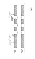
- the first mechanism is shown in Fig. 11 .
- a scenario is depicted where the UE aggregates two carriers, namely a first carrier on frequency f1 of a first cell and a second carrier on frequency f2 of a second cell.
- a case shall be considered in the following where the frequency of the aggregated carrier from the first cell is affected by the IDC problem.
- the eNB After the UE detects an IDC problem, the eNB is informed by the UE indicating the interference condition. In response thereto, the eNB commands the UE to deactivate the carrier of the first cell. Subsequent to the reception of the deactivation command from the eNB, the UE processes and deactivates the carrier. Processing of a deactivation command may result in a processing delay ( ⁇ Tproc). In response to processing the deactivation command, the UE deactivates the carrier of the first cell
- the eNB commands the UE to re-activate the carrier of the first cell. Subsequent to the reception and processing of the re-activation command, the carrier is reactivated again by the UE. Also the processing of the deactivation command may result in a processing delay.
- deactivation and reactivation of the affected carrier(s) is commanded by the eNB to the UE using activation / deactivation mechanism of LTE Rel10.
- the processing delay at the UE may amount to 8 subframes (8ms).
- a scenario is illustrated where the UE aggregates two carriers, namely a first carrier on frequency f1 of the first cell and a second carrier on frequency f2 of the second cell.
- a case shall be considered in the following where the frequency of the aggregated carrier of the first cell is affected by the IDC problem.
- the UE detects an IDC problem and indicates it to the eNB by reporting an IDC interference indication. Yet, upon notification of the IDC problem,the eNB configures an appropriate DRX scheme, as described in the prior art section. Also in this case, coexistence interference can be avoided.
- the off-duration ( ⁇ T off) during which no scheduling of the UE is not possible, amounts to the time between the deactivation command by the eNB and the elapse of the processing delay after the activation command by the eNB.
- the described mechanism suffers from the drawback of lost scheduling opportunities on the first cell.
- scheduling opportunities are lost due to the fact that the eNB leaves knowledge of an exact access pattern of the interfering radio technology out of consideration when signaling the activation / deactivation command to the UE. It may be assumed that the knowledge of the exact pattern of the interfering radio technology is reported to the eNB as part of the IDC interference indication message.
- the missed scheduling opportunities result in a loss of throughput for the UE.
- a DRX scheme may only be configured for all carriers aggregated by an UE solution and does not allow for exceptions of certain carriers of the cells, respective.
- the DRX opportunities equally apply to the carrier(s) affected by coexistence interference as well as those carrier(s) not affected by coexistence interference.
- the carrier of the first cell is deactivated by the UE during the configured DRX opportunity indicated as off-duration ( ⁇ Toff) but also the carrier of the second cell is deactivated by the UE during the same configured DRX opportunity.
- the eNB may only utilize the existing scheduling opportunities (i.e. excluding the off-duration) for both, the affected and the unaffected carriers. Hence, also in this case scheduling opportunities are lost, as denoted by the dashed line in Fig. 14 , on the unaffected carriers and throughput is degraded.
- the eNB signals an activation and deactivation command to avoid in-device coexistence interference. Extending this mechanism to reduce losses of scheduling opportunities, the eNB could potentially make use of the additional knowledge of the exact access pattern of the interfering radio technology reported as part of the IDC interference indication message.
- the eNB could be adapted to signal a deactivation command for time periods when interference for communication on the affected carrier(s) is to be expected, and by signaling an activation command for time periods where no interference for communication on the affected carrier(s) is to be expected.
- the eNB could activate and deactivate the affected carrier(s) based on the LTE-on / LTE-off pattern that was suggested by the UE in the IDC interference indication or based on an adaptation of this pattern that the eNB considers suitable.
- the extended mechanism requires control by the eNB to command the UE to activate and deactivate communications on the affected carrier(s). Every deactivation and subsequent re-activation of communication by the UE on the affected carrier(s) requires transmission of two commands, namely a respective activation and deactivation command.
- activation /deactivation commands require a processing time delay ( ⁇ Tproc) at the UE.
- ⁇ Tproc processing time delay
- the eNB cannot rely on an instantaneous activation/ deactivation of communication on the affected carrier(s).
- the eNB has to consider network delays and according guard times before the eNB can expect the UE to have applied the activation/ deactivation command and can schedule the UE by the eNB is possible.
- Network delays may result from possible retransmissions of the activation / deactivation command; the eNB does not know in advance the exact point in time where the carrier is activated or deactivated by the UE.
- the processing delay of the transmitted activation / deactivation command theoretically limits the shortness of the opportunity of scheduling the UE on the affected carrier(s) by the eNB such that it can never be less than twice the processing time ( ⁇ Ton ⁇ 2* ⁇ Tproc).
- ⁇ Ton the processing delay of the transmitted activation / deactivation command
- the present invention strives to avoid the various disadvantages mentioned above.
- One object of the invention is to propose an improved in-device coexistence interference avoiding mechanism for a mobile terminal that has aggregated more than one carrier in order to maximize scheduling opportunities.
- an improved in-device interference avoiding mechanism for a mobile terminal is suggested that reduces the signaling overhead in transmitting an activation/deactivation pattern.
- the invention suggests an improved in-device coexistence interference avoiding mechanism that differentiates between affected and non-affected carrier(s), which a mobile terminal has aggregated, and uses an IDC interference indication for configuring an activation/deactivation pattern for the affected carrier(s).
- Configuring a mobile terminal with the activation/deactivation pattern allows the mobile terminal to autonomously deactivate and re-activate communication via the affected carriers at subframes avoiding the access pattern of an interfering radio technology.
- the IDC interference indication message exemplary includes information on the interfering radio technology and an access pattern of that interfering radio technology.
- the IDC interference indication message may directly be used for determining an activation/deactivation pattern for the mobile terminal.
- the approach of the invention to provide the mobile terminal and not the base station with sufficient information such that the mobile terminal is enabled to autonomously perform deactivation and re-activation of communication via the affected carrier(s). Accordingly, the deactivation and re-activation of affected carrier(s) by the mobile terminal does not require transmission of separate activation and deactivation commands and is not delayed due to the processing of the commands by the mobile terminal.
- the invention provides for a method for avoiding in-device coexistence, IDC, interference by a mobile terminal in a mobile communication system.
- the mobile terminal is in communication with an aggregation access point via a first cell and a second cell and is in communication with a wireless communication device.
- the mobile terminal detects an interference condition between the communication with the aggregation access point via one of the first or second cell and the communication with the wireless communication device.
- the mobile terminal reports, to the aggregation access point, an IDC interference indication for the one of the first or second cell on which the interference condition is detected.
- the mobile terminal then receives, from the aggregation access point, an activation/deactivation pattern for the one of the first or second cell for which the IDC interference indication is reported, the activation/deactivation pattern indicating an off-duration and an offset specifying a time-period during which communication via the one of the first or second cell is to be deactivated. Based on the off-duration and the offset indicated in the received activation/deactivation pattern the mobile terminal determines a first subframe from which on communication via the one of the first or second cell is to be deactivated and a second subframe, succeeding the first subframe, from which on communication via the one of the first or second cell is to be re-activated. The mobile terminal thereafter deactivates and re-activates the one of the first or second cell at the determined first and second subframe, respectively, for avoiding IDC interference between communication with the aggregation access point and communication with the wireless communication device.
- the activation/deactivation pattern additionally includes an ID of the one of the first or second cell, and optionally IDs of other cells, indicating the cells for which the determining step and the deactivation and re-activation step is to be performed.
- the activation/deactivation pattern additionally indicates an on-duration which together with the off-duration and the offset specifies a time-period during which communication via the one of the first or second cell is to be re-activated.
- the mobile terminal determines further subframes, succeeding the second subframe, from which on communication via the one of the first and second cell is alternatively deactivated and re-activated. Then, the mobile terminal subsequently deactivates and re-activates the one of the first or second cell alternatively at the determined further subframes.
- the mobile terminal in case the mobile terminal receives, from the aggregation access point, a medium access control, MAC, control element, ordering an activation/deactivation for the one of the first or second cell after the mobile terminal has received the activation/deactivation pattern and after it has determined the first and second subframes for the one of the first or second cell, the mobile terminal ignores the MAC control element ordering the activation/deactivation and the mobile terminal performs deactivation and re-activation at the determined first and second subframe, respectively.
- a medium access control, MAC, control element ordering an activation/deactivation for the one of the first or second cell after the mobile terminal has received the activation/deactivation pattern and after it has determined the first and second subframes for the one of the first or second cell
- the mobile terminal in case the mobile terminal receives, from the aggregation access point, a medium access control, MAC, control element, ordering a deactivation of the one of the first or second cell, the mobile terminal deactivates communication via the one of the first or second cell after processing the received MAC control element, and the mobile terminal the at least one deactivation and re-activation of communication is only performed at the determined subframes for the one of the first or second cell after the mobile terminal has received, from the aggregation access point, and after the mobil terminal has processed another MAC control element ordering the activation of the one of the first or second cell.
- the mobile terminal in case the activation/deactivation pattern additionally indicates an on-duration, and in case the processing by the mobile terminal of the other received MAC control element, ordering the activation of the one of the first or second cell, is completed at a time for which the received activation/deactivation pattern specifies that communication via the one of the first or second cell is to be re-activated, the mobile terminal additionally activates communication via the one of the first or second cell is performed by the mobile terminal after completion of the processing of the other MAC control element.
- the mobile terminal triggers a power headroom report, PHR, prior to the re-activation of the one of the first or second cell at the determined second subframe.
- the reconfigured activation/deactivation pattern triggers reconfiguration by the mobile terminal of the deactivating and re-activating step by excluding the one of the first or second cell from being deactivated and re-activated at the determined first and second subframe, respectively.
- the activation/deactivation pattern is signalled from the aggregation access point to the mobile terminal as a radio resource control, RRC, message.
- RRC radio resource control
- the offset indicated in the received activation/deactivation pattern is based on the reported IDC interference condition.
- the IDC interference indication includes a desired time division multiplex, TDM, pattern indicating a periodicity of the TDM pattern and a scheduling period or an unscheduled period.
- the mobile terminal deactivates the one of the first or second cell including: stopping transmission of SRS, stopping reporting of CQI/PMI/RI/PTI, stopping UL-SCH transmissions and stopping monitoring of PDCCH.
- the aggregation access point receives, from the mobile terminal, an IDC interference indication for the one of the first or second cell on which the interference condition is detected by the mobile terminal. Based on the received IDC interference indication, the aggregation access point determines an activation/deactivation pattern for the mobile terminal, the activation/deactivation pattern indicating an off-duration and an offset specifying a time-period during which communication by the mobile terminal via the one of the first or second cell is to be deactivated. Then, the aggregation access point reports the determined activation/deactivation pattern to the mobile terminal.
- the invention additionally provides for a method for avoiding in-device coexistence, IDC, interference by a mobile terminal in a mobile communication system.
- the mobile terminal is in communication with an aggregation access point via a first cell and a second cell, and is in communication with a wireless communication device.
- the mobile terminal detects an interference condition between the communication with the aggregation access point via one of the first or second cell and the communication with the wireless communication device.
- the mobile terminal reports an IDC interference indication for the one of the first or second cell on which the interference condition is detected, the IDC interference indication including a desired activation/deactivation pattern for the one of the first or second cell indicating an off-duration and an offset specifying a time-period during which communication via the one of the first or second cell is to be deactivated.
- the mobile terminal determines a first subframe from which on communication via the one of the first or second cell is to be deactivated and a second subframe, succeeding the first subframe, from which on communication via the one of the first or second cell is to be re-activated. Then, the mobile terminal deactivates and re-activates the one of the first or second cell at the determined first and second subframe, respectively, for avoiding IDC interference between communication with the aggregation access point and communication with the wireless communication device.
- the mobile terminal only deactivates and re-activates communication for the one of the first or second cell on which the interference condition is detected, after elapse of a predetermined time-duration starting from the step of reporting the IDC interference indication.
- the mobile terminal does not deactivate and re-activate communication, in case the mobile terminal receives a medium access control, MAC, control element including the R-bit equal one prior to the elapse of the predetermined time-duration.
- MAC medium access control
- the mobile terminal receives another activation/deactivation pattern for the one of the first or second cell for which the IDC interference indication is reported, the activation/deactivation pattern indicating another off-duration and another offset specifying another time-period during which communication via the one of the first or second cell is to be deactivated.
- the mobile terminal determines, based on the other off-duration and the other offset indicated in the received other activation/deactivation pattern, the first and second subframe and the mobile terminal performs deactivation and the re-activation using the first and second subframe.
- the invention further provides for a mobile terminal for avoiding in-device coexistence, IDC, interference in a mobile communication system, the mobile terminal being in communication with an aggregation access point via a first cell and a second cell, the mobile terminal additionally being in communication with a wireless communication device, the method comprising the steps.
- a processor of the mobile terminal is configured to detect an interference condition between the communication with the aggregation access point via one of the first or second cell and the communication with the wireless communication device
- a transmitting circuit of the mobile terminal is configured to report, to the aggregation access point, an IDC interference indication for the one of the first or second cell on which the interference condition is detected.
- a receiving circuit of the mobile terminal is configured to receive, from the aggregation access point, an activation/deactivation pattern for the one of the first or second cell for which the IDC interference indication is reported, the activation/deactivation pattern indicating an off-duration and an offset specifying a time-period during which communication via the one of the first or second cell is to be deactivated.
- the processor of the mobile terminal is further configured to determine, based on the off-duration and the offset indicated in the received activation/deactivation pattern, a first subframe from which on communication via the one of the first or second cell is to be deactivated and a second subframe, succeeding the first subframe, from which on communication via the one of the first or second cell is to be re-activated.
- the processor of the mobile terminal is additionally configured to deactivate and re-activate the one of the first or second cell at the determined first and second subframe, respectively, for avoiding IDC interference between communication with the aggregation access point and communication with the wireless communication device
- activation/deactivation pattern additionally includes an ID of the one of the first or second cell, and optionally IDs of other cells, indicating the cells for which the processor of the mobile terminal is configured to determine the first and second subframe and is further configured to deactivate and re-activate communication at the determined first and second subframe.
- the activation/deactivation pattern additionally indicates an on-duration which together with the off-duration and the offset specifies a time-period during which communication via the one of the first or second cell is to be re-activated.
- the processor of the mobile terminal is additionally configured to determine succeeding the second subframe, from which on communication via the one of the first and second cell is alternatively deactivated and re-activated.
- the processor of the mobile terminal is additionally configured to deactivate and re-activate the one of the first or second cell alternatively at the determined further subframes.
- the receiving circuit of the mobile terminal receives, from the aggregation access point, a medium access control, MAC, control element, ordering an activation/deactivation for the one of the first or second cell after having received the activation/deactivation pattern and after the processor of the mobile terminal has determined the first and second subframes for the one of the first or second cell
- the receiving circuit and the processor of the mobile terminal accordinglye additionally configured to ignore the MAC control element ordering the activation/deactivation and to perform the deactivation and re-activation at the determined first and second subframe, respectively.
- the processor of the mobile terminal in case the receiving circuit of the mobile terminal receives, from the aggregation access point, of a medium access control, MAC, control element, ordering a deactivation of the one of the first or second cell, the processor of the mobile terminal is additionally configured to deactivate the communication via the one of the first or second cell after processing the received MAC control element, and the processor of the mobile terminal is additionally configured to only deactivate and re-activate communication at the determined subframes for the one of the first or second cell after the receiving circuit of the mobile terminal receives, from the aggregation access point, and after the processor of the mobile terminal processes another MAC control element ordering the activation of the one of the first or second cell.
- the processor of the mobile terminal in case the activation/deactivation pattern additionally indicates an on-duration, and in case processing, by the processor of the mobile terminal, of the other by the receiving circuit received MAC control element, ordering the activation of the one of the first or second cell, is completed at a time for which the by the receiving circuit received activation/deactivation pattern specifies that communication via the one of the first or second cell is to be re-activated, the processor of the mobile terminal is additionally configured to activate communication via the one of the first or second cell after completion of the processing of the other MAC control element.
- the processor of the mobile terminal is further configured to triggering a power headroom report, PHR, prior to the re-activation of the one of the first or second cell at the determined second subframe.
- the processor of the mobile terminal is additionally configured to trigger, based on the received reconfigured activation/deactivation pattern, reconfiguration of the deactivation and re-activation of communication by excluding the one of the first or second cell from being deactivated and re-activated at the determined first and second subframe, respectively.
- the activation/deactivation pattern is signalled from the aggregation access point to the mobile terminal as a radio resource control, RRC, message.
- RRC radio resource control
- the offset indicated in the received activation/deactivation pattern is based on the reported IDC interference condition.
- the IDC interference indication includes a desired time division multiplex, TDM, pattern indicating a periodicity of the TDM pattern and a scheduling period or an unscheduled period.
- the processor of the mobile terminal is additionally configured to deactivate the one of the first or second cell includes stopping transmission of SRS, stopping reporting of CQI/PMI/RI/PTI, stopping UL-SCH transmissions and stopping monitoring of PDCCH.
- the invention also provides for a mobile terminal for avoiding in-device coexistence, IDC, interference in a mobile communication system
- the mobile terminal is in communication with an aggregation access point via a first cell and a second cell, and is in communication with a wireless communication device.
- a processor of the mobile terminal is configured to detect an interference condition between the communication with the aggregation access point via one of the first or second cell and the communication with the wireless communication device.
- a transmitting circuit of the mobile terminal is configured to report an IDC interference indication for the one of the first or second cell on which the interference condition is detected, the IDC interference indication including a desired activation/deactivation pattern for the one of the first or second cell indicating an off-duration and an offset specifying a time-period during which communication via the one of the first or second cell is to be deactivated.
- the processor of the mobile terminal is further configured to determine, based on the off-duration and the offset indicated in the desired activation/deactivation pattern, a first subframe from which on communication via the one of the first or second cell is to be deactivated and a second subframe, succeeding the first subframe, from which on communication via the one of the first or second cell is to be re-activated.
- the processor of the mobile terminal is additionally configure to deactivate and re-activate the one of the first or second cell at the determined first and second subframe, respectively, for avoiding IDC interference between communication with the aggregation access point and communication with the
- the processor of the mobile terminal is configured to deactivate and re-activating step are only performed for the one of the first or second cell on which the interference condition is detected, after elapse of a predetermined time-duration starting from the step of reporting the IDC interference indication.
- the processor of the mobile terminal is configured not to perform deactivating and re-activating communication, in case of a reception of a medium access control, MAC, control element including the R-bit equal one prior to the elapse of the predetermined time-duration.
- the receiving circuit of the mobile terminal is further configured to receive another activation/deactivation pattern for the one of the first or second cell for which the IDC interference indication is reported, the activation/deactivation pattern indicating another off-duration and another offset specifying another time-period during which communication via the one of the first or second cell is to be deactivate.
- the processor of the mobile terminal is additionally configured to determine, based on the other off-duration and the other offset indicated in the received other activation/deactivation pattern, the first and second subframe and the processor of the mobile terminal is additionally configured to deactivate and to re-activate communication using the first and second subframe.
- the invention further provides for an aggregation access point for assisting a mobile terminal to avoid in-device coexistence, IDC, interference in a mobile communication system.
- the aggregation access point is in communication with to mobile terminal via a first cell and a second cell.
- a receiving circuit of the aggregation access point is configured to receive, from the mobile terminal, an IDC interference indication for one of the first or second cell on which an interference condition is detected by the mobile terminal.
- a processor of the aggregation access point is configured to determine, based on the received IDC interference indication, an activation/deactivation pattern for the mobile terminal, the activation/deactivation pattern indicating an off-duration and an offset specifying a time-period during which communication by the mobile terminal via the one of the first or second cell is to be deactivated.
- a transmitting circuit of the aggregation access point is configured to report the determined activation/deactivation pattern to the mobile terminal.
- mobile terminal corresponds to the mobile terminal previously described.
- the invention even further provides for a computer readable medium storing instructions that, when executed by a processor of a mobile terminal, cause the mobile terminal to avoiding in-device coexistence, IDC, interference, the mobile terminal being in communication with an aggregation access point via a first cell and a second cell, the mobile terminal additionally being in communication with a wireless communication device, by: detecting an interference condition between the communication with the aggregation access point via one of the first or second cell and the communication with the wireless communication device; reporting, to the aggregation access point, an IDC interference indication for the one of the first or second cell on which the interference condition is detected; receiving, from the aggregation access point, an activation/deactivation pattern for the one of the first or second cell for which the IDC interference indication is reported, the activation/deactivation pattern indicating an off-duration and an offset specifying a time-period during which communication via the one of the first or second cell is to be deactivated; determining, based on the off-duration and the offset indicated
- the invention additionally provides for a computer readable medium storing instructions that, when executed by a processor of a mobile terminal, cause the mobile terminal to avoiding in-device coexistence, IDC, interference, the mobile terminal being in communication with an aggregation access point via a first cell and a second cell, the mobile terminal additionally being in communication with a wireless communication device, by: detecting an interference condition between the communication with the aggregation access point via one of the first or second cell and the communication with the wireless communication device; reporting an IDC interference indication for the one of the first or second cell on which the interference condition is detected, the IDC interference indication including a desired activation/deactivation pattern for the one of the first or second cell indicating an off-duration and an offset specifying a time-period during which communication via the one of the first or second cell is to be deactivated; determining, based on the off-duration and the offset indicated in the desired activation/deactivation pattern, a first subframe from which on communication via the one of the first or second cell is to be
- the computer readable medium is storing instructions that, when executed by a processor of a mobile terminal, cause the mobile terminal to perform the steps of the method for avoiding in-device coexistence, IDC, interference, according to one of the various exemplary embodiments described herein.
- the invention also provides for a computer readable medium storing instructions that, when executed by a processor of a aggregation access point, cause the aggregation access point to assist a mobile terminal to avoid in-device coexistence, IDC, interference in a mobile communication system, the aggregation access point being in communication with to mobile terminal via a first cell and a second cell, by: receiving, from the mobile terminal, an IDC interference indication for one of the first or second cell on which an interference condition is detected by the mobile terminal; determining, based on the received IDC interference indication, an activation/deactivation pattern for the mobile terminal, the activation/deactivation pattern indicating an off-duration and an offset specifying a time-period during which communication by the mobile terminal via the one of the first or second cell is to be deactivated; a transmitting circuit configured to report the determined activation/deactivation pattern to the mobile terminal.
- the invention may be advantageously used for example in a mobile communication system such as 3GPP LTE (Release 8/9) and LTE-A (Release 10/11) communication systems as described in the technical background section above, but the invention is not limited to its use in this particular exemplary communication network.
- a mobile communication system such as 3GPP LTE (Release 8/9) and LTE-A (Release 10/11) communication systems as described in the technical background section above, but the invention is not limited to its use in this particular exemplary communication network.
- wireless communication device is used in the following description to refer to any kind of device allowing for wireless communication with the mobile terminal according to the invention.
- the “wireless communication device” may be a device enabled for communication via ISM/GSSN frequency bands.
- devices can be a WIFI access point or WIFI router, a Bluetooth headset, a Bluetooth stereo system, or even a GSSN satellite.
- the invention aims to provide for a maximization of scheduling opportunities of the mobile terminal (user equipment in the 3GPP context) by a base station (eNodeB or Node B in the 3GPP context) in a scenario where the mobile terminal is assumed to operate multiple in-device transceiver modules for different radio technologies in a same transmission time interval (e.g. one or more sub-frames).
- the invention separately regards in-device coexistence interference for a plurality of carriers which the mobile terminal has aggregated of different cells.
- the mobile terminal Upon the mobile terminal detecting an interference condition between one or a sub-set of the plurality of aggregated carriers and communications via the different (i.e. interfering) radio technology, the mobile terminal is to be configured to perform communication on the affected of the plurality of carrier(s) according to an activation/deactivation pattern so as to avoid in-device coexistence interference. At the same time, the mobile terminal may continue communicating on the non-affected of the plurality of cell(s).
- the activation/deactivation pattern is determined for the affected of the plurality of carriers of the mobile terminal in order to mask the access pattern of the different (i.e. interfering) radio technology which has resulted in the interference condition.
- Configuring the mobile terminal with the activation/deactivation pattern allows the mobile terminal to deactivate and re-activate communication via the affected of the plurality of carriers at subframes avoiding the access pattern of an interfering radio technology.
- IDC interference procedure is already specified for mobile terminals in 3GPP LTE (Release 11).
- the IDC interference procedure prescribes the mobile terminal to report an IDC interference indication for assistance to the base station in order to avoid an interference condition.
- This IDC interference indication includes information on interfering radio technology and an access pattern of the interfering radio technology.
- an aspect of the invention is to adapt the in-device coexistence avoidance mechanism to separately consider affected and non-affected carrier(s), which a mobile terminal has aggregated.
- an activation/deactivation pattern is suggested, based on an existing IDC interference indication, which can be configured at the mobile terminal for the affected carrier(s) only.
- the activation/deactivation pattern allows the mobile terminal to deactivate and re-activate communication via the affected carriers at subframes avoiding the access pattern of an interfering radio technology.
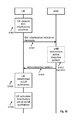
- FIG. 16 a sequence diagram of an improved in-device coexistence interference avoiding mechanism to be performed by a mobile terminal (UE) according to a first embodiment of the invention is shown.
- the mobile terminal utilizes a received activation/deactivation pattern for avoiding in-device coexistence interference on affected carriers. This behavior will be described in more detail below.
- the mobile terminal detects an in-device coexistence interference condition between communication on one or a subset of a plurality of aggregated carriers of different cells and communication with the wireless communication device.
- an interference condition is detected for at least one of the plurality of aggregated carriers and at least another one of the aggregated carriers is not-affected by the communication with the wireless communication device.
- the mobile terminal reports, in step S1602, an in-device coexistence, IDC, interference indication for the affected of the plurality of subcarriers on which the interference condition is detected to the base station.
- the IDC interference indication includes a desired time division multiplex, TDM, pattern indicating a periodicity of the TDM pattern and a scheduling period or an unscheduled period.
- TDM time division multiplex
- Alternative implementations of the IDC interference indication are also possible such that the above implementation should not be understood as limiting the invention.
- the base station determines, in step S1603, an activation/deactivation pattern for the mobile terminal to avoid on the affected carrier(s) ongoing or reoccurring interference conditions.
- the activation/deactivation pattern includes an off-duration and offset. Both values, the off-duration and the offset, specify a time-period during which communication on the affected carrier(s) is to be deactivated by the mobile terminal.
- the offset specifies an alignment of the off-duration, i.e. when the deactivation and the successive re-activation are to be performed. The offset may be based on the reported IDC interference condition. This implementation of the activation/deactivation pattern focuses on avoiding an ongoing interference condition.
- the activation/deactivation pattern includes an off-duration, an on-duration and an offset. All three values, namely off-duration, on-duration and offset, specify a time period during which the communication on the affected carrier(s) is to be deactivated and another time period during which the communication is to be re-activated. Also in this implementation, the offset specifies an alignment of the off-duration and the successive on-duration. Further, the mobile terminal is adapted to alternatively deactivate and re-activated communication on the affected carrier(s) such that this implementation of the activation/deactivation pattern focuses on avoiding a reoccurring interference condition.
- the activation/deactivation pattern includes ID(s) of cell(s) indicating respective carrier(s) aggregated by the mobile terminal.
- the ID(s) of cell(s), included in the activation/deactivation pattern may indicated the carrier(s) affected by the interference condition.
- the ID(s) of cell(s) may not only be restricted to carrier(s) affected by the interference condition, but, may precautionary indicate additional carrier(s) which are also likely to be affected by the interference condition.
- the base station transmits, in step S1604, the activation/deactivation pattern to the mobile terminal.
- the activation/deactivation pattern is conveyed in a new UL-DCCH Message (i.e. RRC signaling) and can also be reused to send the updated assistant information, including the case where a carrier is to be excluded from the one or subset of carriers for which communication is deactivated / re-activated by the mobile terminal according to the activation/deactivation pattern.
- RRC signaling i.e. RRC signaling
- Other signaling procedures like MAC CE can also be utilized to convey to the mobile terminal the activation/deactivation pattern.
- step S1605 the mobile terminal determines, based on the received activation/deactivation pattern at least two subframes, namely a first subframe from which on communication via the affected carrier(s) is to be deactivated and a second subframe, succeeding the first subframe, from which on communication via the one of the first or second cell is to be re-activated.
- a determination by the mobile terminal of the two subframes corresponds to the implementation of the activation/deactivation pattern including the off-duration and the offset.
- the mobile terminal determines a plurality of subframes, namely a first subframe from which on communication via the affected carrier(s) is to be deactivated and a second subframe, succeeding the first subframe, from which on communication via the one of the first or second cell is to be re-activated, a third subframe, succeeding the second subframe, from which on communication via the affected carrier(s) is to be activated, etc., in order to alternatively deactivate and re-activated communication on the affected carrier(s) according to the received activation/deactivation pattern.
- the mobile terminal determines a plurality of subframes corresponding to start- and end-times of the time-periods during which communication on the affected carrier(s) is to be alternatively deactivated and re-activated by the mobile terminal.
- step S1606 the mobile terminal deactivates and re-activates the affected carrier(s) at the determined first and second subframe, respectively, for avoiding IDC interference between communication with the base station and communication with the wireless communication device.
- the mobile terminal performs, in addition to deactivating and re-activating the affected carrier(s) at the determined first and second subframe, subsequent deactivating and re-activating steps for alternatively deactivating and re-activating the affected carrier(s) at further determined subframes (i.e. including the third subframe), succeeding the second subframe.
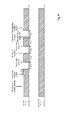
- the short but repetitive type of interference with respect to communication on the first carrier of the first cell is denoted by the dashed line in Fig. 17 .
- the previously described improved in-device coexistence interference avoiding mechanism according to the first embodiment of the invention is applied in the exemplary scenario of the invention.
- the mobile terminal is "configured" with the pattern by the base station.
- the term “configured” refers, in the context of the invention, to a state of the mobile terminal in which it is provided with an activation/deactivation pattern but has not necessarily started performing deactivation and re-activation of communication on the affected carrier(s).
- the offset value included in the received activation/deactivation pattern may prescribe a delay ( ⁇ Toffset) between time-point when the mobile terminal is "configured” and the time-point when the mobile terminal deactivates communication on the affected carrier(s) for the first time.
- the off-duration ( ⁇ Toff) enacted (actually carried out) by the mobile terminal i.e. the time period between the time-point when the mobile terminal deactivates and subsequently re-activates, due to the "configured" pattern, communication on the affected carrier(s), as shown in Fig. 17 , corresponds to the time-period indicated by the activation/deactivation pattern during which communication on the affected carrier(s) is to be deactivated.
- there is no delay requirements e.g. due to a processing of activation/deactivation commands from the base station which forces unduly extending the off-duration actually carried out by the mobile terminal (as is, for instance, the case in the extended mechanism illustrated in Fig. 15 ).
- the improved in-device coexistence interference avoiding mechanism allows minimizing the off-duration actually carried out by the mobile terminal.
- the off-duration is reduced to the time-period indicated in the received activation/deactivation pattern and, thereby, scheduling opportunities are maximized for the mobile terminal.
- the on-duration i.e. scheduling opportunity ( ⁇ Ton) enacted (actually carried out) by the mobile terminal (i.e. the time period between the time-point when the mobile terminal re-activates and de-activates, due to the "configured" pattern, communication on the affected carrier(s), as shown in Fig. 17 ) also corresponds to the time-period indicated by the activation/deactivation pattern, i.e. in case of the second implementation of the activation/deactivation pattern. Also for the on-duration, there is no delay requirement which would result in losing on-duration time i.e. loosing scheduling opportunities for the mobile terminal.
- the mobile terminal may wait for the next activation of communication on the previously affected carrier(s), to then report on said carrier(s) to the base station an IDC interference indication that the problem is solved.
- the base station then reconfigures the activation/ deactivation pattern to exclude at least the carrier, for which the "problem solved" IDC interference indication is reported, from deactivation / re-activation by the mobile terminal.
- the mobile terminal may not wait for the next activation of communication on the previously affected carrier(s) but instead report on a non-affected carrier(s) to the base station an IDC interference indication that the problem is solved.
- the base station then reconfigures the activation/deactivation pattern to exclude at least the carrier from activation/deactivation by the mobile terminal at an earlier point in time.
- the following fields are included in the activation/deactivation pattern received by the mobile terminal from the base station:
- the base station configures the mobile terminal with the above values by using for example an RRC message. After receiving the configuration, the mobile terminal derives exact subframe numbers for activation and deactivation and applies them to the identified carrier(s). The mobile terminal then periodically repeats the configured activation/deactivation pattern until the network/base station reconfigures the mobile terminal or revokes the activation/deactivation configuration.
- the term "deactivation of a carrier” or “deactivate communication on a carrier” refers to the time-period of a mobile terminal where: no transmission of SRS is performed, no CQI/PMI/RI/PTI are reported, no UL-SCH transmission are carried out, and no monitoring of PDCCH is performed.
- the mobile terminal behavior during the deactivated time-period is the same as the behavior currently defined for deactivated SCells.
- Fig. 18 a variation of the improved in-device coexistence interference avoiding mechanism according to the first embodiment of the invention is shown. This variation focuses on improving the scheduling decision of carrier(s) affected by an IDC interference condition by the base station for affected carriers(s) i.e. for which an IDC interference indication has been reported.
- the mobile terminal In response to the reception of the activation/deactivation pattern by the mobile terminal, the mobile terminal not only deactivates and reactivates communication on the affected carrier(s) but also triggers a power headroom report, PHR, prior to the re-activation of the affected carrier(s) of the respective cell at the determined subframe.
- PHR power headroom report
- a new or additional PHR trigger is configured based on the subframes determined for re-activation of the affected subcarrier(s).
- the PHR trigger triggers a power headroom report, PHR, on the respective affected carrier(s) a predefined number of subframes prior to the re-activation of communication on the cell (i.e. prior to the time-point of change from deactivated to activated state).
- the predefined number of subframes is 6 subframes prior to the state change.
- the mobile terminal may assist the bases station with a PHR that closely resembles available power headroom of the mobile terminal at the time of re-activation of communication on the affected carrier(s) of the respective cell(s).
- the base station i.e. network
- Another sub-aspect of the invention focuses the interrelationship between the application of the activation/deactivation pattern by the mobile terminal, as part of the improved in-device coexistence interference avoiding mechanism according to the first embodiment, and a reception of activation/deactivation commands by the mobile terminal.
- Activation/deactivation commands are transmitted by a base station to a mobile terminal for commanding the activation / deactivation of indicated carrier(s) by the mobile terminal.
- the activation/deactivation commands are commonly transmitted in the form of MAC control elements and have been already discussed in the technical background section.
- an activation/deactivation command is similar to the application of the activation/deactivation pattern by the mobile terminal.
- the activation/deactivation commands are transmitted by a base station for various reasons (e.g. power saving) and are not restricted to IDC interference conditions as is the case of application of activation/deactivation patterns.
- the activation/deactivation commands are disadvantageous for avoiding IDC interference conditions as has been explained in the technical background section, e.g. with respect to Fig. 13 and 15 .
- the application of the activation/deactivation pattern takes precedence over the reception of activation/deactivation commands sent by the base station via MAC CE to the mobile terminal. Accordingly, the mobile terminal ignores for a carrier that is currently configured with an activation/deactivation pattern any activation/deactivation commands received in form of a MAC CE.
- the mobile terminal receives, from the base station, a medium access control, MAC, control element, ordering an activation/deactivation for the affected carrier(s) of respective cells after having received, in step S1604 of Fig. 16 , the activation/deactivation pattern and after having determined, in step S1605 of Fig. 16 , the first and second subframe for the affected carrier(s), the MAC control element ordering the activation/deactivation is ignored by the mobile terminal and the deactivation and re-activation, in step S1606, are performed at the determined first and second subframe, respectively.
- a medium access control, MAC, control element ordering an activation/deactivation for the affected carrier(s) of respective cells after having received, in step S1604 of Fig. 16 , the activation/deactivation pattern and after having determined, in step S1605 of Fig. 16 , the first and second subframe for the affected carrier(s), the MAC control element ordering the activation/deactivation is ignored by the mobile terminal and the deactivation and
- the base station first needs to remove the carrier from the configured activation/deactivation pattern before it can entirely deactivate the carrier with an activation/deactivation command in form of MAC CE.
- activated carrier(s) may always be configured, by the base station, with an activation / deactivation pattern.
- the reception of activation/deactivation commands sent by the base station via MAC CE to the mobile terminal take precedence over the application of the activation/deactivation pattern.
- the application of the activation/deactivation pattern is interrupted by a deactivation/activation command according this other variation of the first embodiment is shown in Fig. 19 .
- the mobile terminal interrupts after reception of an activation/deactivation command indicating the deactivation of affected carrier(s) for which also an activation/deactivation pattern is configured, any re-activations and deactivations to be performed by the mobile terminal in response to the activation/deactivation pattern.
- the mobile terminal deactivates communication via the affected carrier(s) after processing ( ⁇ Tproc) of the received MAC control element, and the mobile terminal resumes deactivating and re-activating at the determined subframes communication on the affected carrier(s) after a reception and after processing ( ⁇ Tproc) of another MAC control element ordering the activation of the affected carrier(s).
- the mobile terminal proceeds with (e.g. immediately) activating the communication on the affected carrier(s) after the completion of the processing of the other received MAC control element.
- communication on the affected carrier(s) is deactivated by the deactivation command received from the base station until the subsequent activation by the activation command from the base station for a time-duration ( ⁇ Toff) corresponding to the time between reception of the deactivation command and reception of the activation command plus the processing delay. This case is shown in Fig. 19 .
- the mobile terminal proceeds with activating the communication on the affected carrier(s), not necessarily immediately, but at a subframe for which the received activation/deactivation pattern specifies that communication on the affected carrier(s) is to be subsequently re-activated.
- a mobile terminal configured with the activation/deactivation pattern for an affected carrier would start following the pattern and, only on reception of an deactivation command via MAC CE; the mobile terminal would deactivate the affected carrier on a longer time frame (i.e. not following the pattern anymore) until reception of an activation command via MAC CE for the same affected carrier.
- This other variation the improved in-device coexistence interference avoiding mechanism according to the first embodiment, as illustrated in Fig. 19 , provides the mobile terminal with further power saving opportunities.
- FIG. 20 a sequence diagram of an improved in-device coexistence interference avoiding mechanism to be performed by a mobile terminal (UE) according to a second embodiment of the invention is shown.
- the mobile terminal suggests a desired activation/deactivation pattern for avoiding in-device interference on affected carriers only and autonomously applies the desired activation/deactivation pattern without approval by the base station. This behavior will be described in more detail below.
- the mobile terminal detects an in-device coexistence interference condition between communication on one or a subset of a plurality of aggregated carriers of different cells and communication with the wireless communication device.
- an interference condition is detected for at least one of the plurality of aggregated carriers and at least another one of the aggregated carriers is not-affected by the communication with the wireless communication device.
- all advantages of the invention can be appreciated.
- the mobile terminal reports, in step S2002, an in-device coexistence, IDC, interference indication for the affected of the plurality of subcarriers on which the interference condition is detected to the base station including a desired activation/deactivation pattern.
- the specified implementation of an IDC interference indication includes means to suggest a desired an on-period and/or off-period determining an activation/deactivation pattern.
- the specified implementation of the IDC interference indication includes a desired time division multiplex, TDM, pattern indicating a periodicity of the TDM pattern (i.e. sum of the off-period and the on-period), and a scheduling period (i.e. on-period) or an unscheduled period (i.e. off-period).
- TDM time division multiplex
- pattern indicating a periodicity of the TDM pattern i.e. sum of the off-period and the on-period
- a scheduling period i.e. on-period
- an unscheduled period i.e. off-period
- the base station After reporting the IDC interference indication to the base station, the base station optionally determines, for instance in step S2304 of Fig. 23 , an (other) activation/deactivation pattern for the mobile terminal to avoid on the affected carrier(s) ongoing or reoccurring interference conditions.
- the base station it is important that the base station has the possibilities of determining an activation/deactivation pattern, however, the base station must not carry out the step of determining the activation/deactivation pattern for actually avoiding IDC interference conditions.
- the base station determines, in step S2003, activation/deactivation pattern for the mobile terminal to avoid on the affected carrier(s) ongoing or reoccurring interference conditions.
- the mobile terminal determines, in step S2004, based on the determined activation/deactivation pattern at least two subframes, namely a first subframe from which on communication on the affected carrier(s) is to be deactivated and a second subframe, succeeding the first subframe, from which on communication via the one of the first or second cell is to be re-activated.
- the mobile terminal After elapse of a predetermined time-duration ( ⁇ T in Fig. 20 ) starting from the step of reporting the IDC interference indication, in step S2002, the mobile terminal deactivates and re-activates, in step S2005, the affected carrier(s) at least at the determined first and second subframe, respectively, for avoiding IDC interference between communication with the base station and communication with the wireless communication device.
- the predetermined time duration ( ⁇ T) amounts to 20 subframes. This time duration allows the base station to respond with a configuration message before the mobile terminal starts deactivating and re-activating, in step S2005, the affected carrier(s) at least at the determined first and second subframe, as will be described below with respect to Fig. 21 and Fig. 22 .
- step S2005 the mobile terminal after elapse of a predetermined time-duration performs, in addition to deactivating and re-activating the affected carrier(s) at the determined first and second subframe, in step S2004, subsequent deactivating and re-activating steps for alternatively deactivating and re-activating the affected carrier(s) at further determined subframes, succeeding the second subframe.
- autonomous application of a desired activation/deactivation pattern by the mobile terminal according to the second embodiment maximizes scheduling opportunities in case of ongoing or reoccurring in-device coexistence interference. Thereby, signaling overhead for configuring the activation/deactivation pattern is reduced.
- FIG. 21 another sequence diagram of the improved in-device coexistence interference avoiding mechanism to be performed by a mobile terminal (UE) including a network objection message according to the second embodiment of the invention is shown.
- the mobile terminal of Fig. 21 performs the same detection step, a same IDC interference indication reporting step, and same determination steps for the activation/deactivation pattern and for the first and second subframe described with respect to Fig 20 such that the repetition thereof has been omitted for conciseness reasons.
- the base station responds by transmitting, in step S2105, a network objection to the mobile terminal.
- the mobile terminal proceeds with not applying the desired activation/deactivation pattern, i.e. the mobile terminal does not deactivate and does not re-activate, in step S2106, the affected carrier(s) at the determined first and second subframe, respectively.
- the network objection is sent in form of a MAC control element where the R-bit is 1.
- the Activation/Deactivation MAC CE is used to convey the network objection information by setting the currently reserved bit (R-bit) to one as shown in Fig. 22 .
- the network objection is sent as an RRC message.
- FIG. 23 yet another sequence diagram of the improved in-device coexistence interference avoiding mechanism to be performed by a mobile terminal (UE) including a network objection message according to the second embodiment of the invention is shown.
- the mobile terminal of Fig. 23 performs the same detection step, a same IDC interference indication reporting step, and same determination steps for the activation/deactivation pattern and for the first and second subframe described with respect to Fig 20 such that the repetition thereof has been omitted for conciseness reasons.
- the base station responds by transmitting, in step S2105, another activation/deactivation pattern for the affected carrier(s) for which the IDC interference indication is reported, the activation/deactivation pattern indicating another off-duration and another offset specifying another time-period during which communication on the affected carrier(s) is to be deactivated.
- step S2305 In case the other activation/deactivation pattern is received, in step S2305, prior to the elapse of the predetermined time duration ( ⁇ T), the determining step is reconfigured to determine, in step S2305, based on the other off-duration and the other offset indicated in the received other activation/deactivation pattern, the first and second subframe and the deactivation and the re-activation step, in step S2307, is performed using the first and second subframe.
- the reception of activation/deactivation commands sent by the base station via MAC CE to the mobile terminal take precedence over the application of the activation/deactivation pattern. Accordingly, after applying the activation/deactivation pattern should the mobile terminal receive a deactivation/activation command in form of a MAC CE as indicated above, it will stop the autonomously applied deactivation/activation pattern. The pattern is also stopped when the mobile terminal detects that the IDC problem is over.
- Another embodiment of the invention relates to the implementation of the above described various embodiments using hardware and software.
- the invention provides a user equipment (mobile terminal) and a eNodeB (base station).
- the user equipment is adapted to perform the methods described herein.
- a computing device or processor may for example be general purpose processors, digital signal processors (DSP), application specific integrated circuits (ASIC), field programmable gate arrays (FPGA) or other programmable logic devices, etc.
- DSP digital signal processors
- ASIC application specific integrated circuits
- FPGA field programmable gate arrays
- the various embodiments of the invention may also be performed or embodied by a combination of these devices.
- the various embodiments of the invention may also be implemented by means of software modules, which are executed by a processor or directly in hardware. Also a combination of software modules and a hardware implementation may be possible.
- the software modules may be stored on any kind of computer readable storage media, for example RAM, EPROM, EEPROM, flash memory, registers, hard disks, CD-ROM, DVD, etc.
Landscapes
- Engineering & Computer Science (AREA)
- Signal Processing (AREA)
- Computer Networks & Wireless Communication (AREA)
- Mobile Radio Communication Systems (AREA)
Priority Applications (5)
| Application Number | Priority Date | Filing Date | Title |
|---|---|---|---|
| EP12184833.7A EP2709415A1 (de) | 2012-09-18 | 2012-09-18 | Maximierung der Planungsgelegenheiten in vorrichtungsinternen Koexistenz-Interferenzszenarien |
| US14/425,308 US9655160B2 (en) | 2012-09-18 | 2013-07-22 | Maximization of scheduling opportunities in in-device coexistence interference scenarios |
| EP13742006.3A EP2898741B1 (de) | 2012-09-18 | 2013-07-22 | Maximierung der planungsgelegenheiten in vorrichtungsinternen koexistenz-interferenzszenarien |
| PCT/EP2013/065428 WO2014044436A1 (en) | 2012-09-18 | 2013-07-22 | Maximization of scheduling opportunities in in-device coexistence interference scenarios |
| JP2015531499A JP6364010B2 (ja) | 2012-09-18 | 2013-07-22 | 装置内共存干渉シナリオにおけるスケジューリング機会の最大化 |
Applications Claiming Priority (1)
| Application Number | Priority Date | Filing Date | Title |
|---|---|---|---|
| EP12184833.7A EP2709415A1 (de) | 2012-09-18 | 2012-09-18 | Maximierung der Planungsgelegenheiten in vorrichtungsinternen Koexistenz-Interferenzszenarien |
Publications (1)
| Publication Number | Publication Date |
|---|---|
| EP2709415A1 true EP2709415A1 (de) | 2014-03-19 |
Family
ID=46875681
Family Applications (2)
| Application Number | Title | Priority Date | Filing Date |
|---|---|---|---|
| EP12184833.7A Withdrawn EP2709415A1 (de) | 2012-09-18 | 2012-09-18 | Maximierung der Planungsgelegenheiten in vorrichtungsinternen Koexistenz-Interferenzszenarien |
| EP13742006.3A Not-in-force EP2898741B1 (de) | 2012-09-18 | 2013-07-22 | Maximierung der planungsgelegenheiten in vorrichtungsinternen koexistenz-interferenzszenarien |
Family Applications After (1)
| Application Number | Title | Priority Date | Filing Date |
|---|---|---|---|
| EP13742006.3A Not-in-force EP2898741B1 (de) | 2012-09-18 | 2013-07-22 | Maximierung der planungsgelegenheiten in vorrichtungsinternen koexistenz-interferenzszenarien |
Country Status (4)
| Country | Link |
|---|---|
| US (1) | US9655160B2 (de) |
| EP (2) | EP2709415A1 (de) |
| JP (1) | JP6364010B2 (de) |
| WO (1) | WO2014044436A1 (de) |
Cited By (7)
| Publication number | Priority date | Publication date | Assignee | Title |
|---|---|---|---|---|
| WO2015157450A1 (en) * | 2014-04-11 | 2015-10-15 | Qualcomm Incorporated | Discontinuous reception (drx)-aware carrier sense adaptive transmission (csat) in shared spectrum |
| WO2016074629A1 (en) * | 2014-11-13 | 2016-05-19 | Qualcomm Incorporated | Control signaling for discontinuous transmission (dtx) in shared spectrum |
| WO2016126383A1 (en) * | 2015-02-02 | 2016-08-11 | Qualcomm Incorporated | Coexistence interference mitigation management for multi-user mimo systems |
| CN107113918A (zh) * | 2015-04-21 | 2017-08-29 | 联发科技股份有限公司 | Wi‑fi p2p及lte数据流量的协调 |
| EP3140938A4 (de) * | 2014-05-08 | 2017-12-20 | Intel Corporation | Systeme und verfahren zur koexistenz-interferenzvermeidung in einer vorrichtung für duale konnektivität |
| CN107950052A (zh) * | 2015-09-02 | 2018-04-20 | 株式会社Ntt都科摩 | 用户终端、无线基站、无线通信方法以及无线通信系统 |
| WO2024172721A1 (en) * | 2023-02-15 | 2024-08-22 | Telefonaktiebolaget Lm Ericsson (Publ) | Handling cell deactivation |
Families Citing this family (29)
| Publication number | Priority date | Publication date | Assignee | Title |
|---|---|---|---|---|
| EP2693815A1 (de) * | 2012-08-03 | 2014-02-05 | Panasonic Corporation | Energiereserven-Berichterstattung zur Vermeidung von Interferenzen bei einer In-Gerätekoexistenz |
| WO2014022959A1 (en) * | 2012-08-06 | 2014-02-13 | Broadcom Corporation | Apparatuses, methods and computer program products related to improvements in autonomous denial prohibition mechanisms |
| US8923880B2 (en) * | 2012-09-28 | 2014-12-30 | Intel Corporation | Selective joinder of user equipment with wireless cell |
| WO2014048498A1 (en) * | 2012-09-28 | 2014-04-03 | Nokia Siemens Networks Oy | Method, apparatuses and computer program for reporting in- device coexistence information |
| US9907094B2 (en) * | 2013-09-16 | 2018-02-27 | Lg Electronics Inc. | Random access procedures in a wireless network employing TDD scheme |
| WO2015041407A1 (en) | 2013-09-20 | 2015-03-26 | Lg Electronics Inc. | Triggering power headroom reporting in tdd system |
| US9474089B2 (en) * | 2013-10-22 | 2016-10-18 | Acer Incorporated | User equipment and base station with configurable carrier |
| WO2015109503A1 (zh) * | 2014-01-23 | 2015-07-30 | 华为技术有限公司 | 终端调度方法、站点与终端 |
| US9955477B2 (en) * | 2014-05-01 | 2018-04-24 | Samsung Electronics Co., Ltd. | Method and apparatus for controlling cell state at subframe level in wireless network |
| US10477482B2 (en) * | 2014-05-13 | 2019-11-12 | Acer Incorporated | Method of handling on-off state of a cell and related communication device |
| JP6613239B2 (ja) * | 2014-09-26 | 2019-11-27 | 株式会社Nttドコモ | 基地局及び処理方法 |
| WO2016068569A2 (en) * | 2014-10-30 | 2016-05-06 | Lg Electronics Inc. | Method and apparatus for handling abnormal situations at cell of unlicensed carrier in wireless communication system |
| JP6442235B2 (ja) * | 2014-11-07 | 2018-12-19 | 株式会社Nttドコモ | ユーザ装置及び基地局 |
| WO2016072443A1 (ja) * | 2014-11-07 | 2016-05-12 | 株式会社Nttドコモ | ユーザ装置、基地局及びアップリンクキャリアアグリゲーション通信方法 |
| US10039148B2 (en) | 2014-12-12 | 2018-07-31 | Apple Inc. | Application-aware multiple wireless radio-access technology coexistence solution and time sharing between multiple radio-access technologies for in-device coexistence |
| US9954668B2 (en) | 2015-03-23 | 2018-04-24 | Qualcomm Incorporated | Co-existence system synchronization on a shared communication medium |
| US20160330697A1 (en) * | 2015-05-08 | 2016-11-10 | Qualcomm Incorporated | Physical uplink control channel management for pucch secondary cell in carrier aggregation |
| WO2017030480A1 (en) * | 2015-08-14 | 2017-02-23 | Telefonaktiebolaget Lm Ericsson (Publ) | Signaling of idc problems |
| JP6773109B2 (ja) | 2016-03-11 | 2020-10-21 | 富士通株式会社 | 無線通信システム及び端末装置 |
| CN108024352A (zh) * | 2016-11-03 | 2018-05-11 | 索尼公司 | 用于资源管理装置、数据库和对象的电子设备和方法 |
| GB2559339A (en) * | 2017-01-31 | 2018-08-08 | Fujitsu Ltd | Measurement configuration signalling in 5G |
| CN109995457A (zh) * | 2017-12-29 | 2019-07-09 | 维沃移动通信有限公司 | 一种干扰处理方法、用户终端和网络侧设备 |
| CN110011752B (zh) * | 2018-01-04 | 2021-10-22 | 维沃移动通信有限公司 | 一种cqi上报方法、终端设备及网络设备 |
| US11483768B2 (en) | 2019-03-28 | 2022-10-25 | Qualcomm Incorporated | Methods and apparatus to facilitate PDCCH monitoring in carrier aggregation for lower power consumption |
| US11658792B2 (en) * | 2019-03-28 | 2023-05-23 | Qualcomm Incorporated | Methods and apparatus to facilitate PDCCH monitoring in carrier aggregation for lower power consumption |
| US10993118B2 (en) * | 2019-05-30 | 2021-04-27 | Ford Global Technologies, Llc | Spectrum sharing infrastructure |
| CN110087326B (zh) * | 2019-05-31 | 2022-06-17 | 中国联合网络通信集团有限公司 | 一种降低谐波干扰的方法及装置 |
| US20230105796A1 (en) * | 2021-10-04 | 2023-04-06 | Charter Communications Operating, Llc | Methods and Apparatus for Supporting Coexistence of Multiple Receiver/Transmitters In A Device Supporting One or More Communications Standards |
| WO2023197175A1 (en) * | 2022-04-12 | 2023-10-19 | Nec Corporation | Method, device and computer readable medium for communications |
Citations (2)
| Publication number | Priority date | Publication date | Assignee | Title |
|---|---|---|---|---|
| US20100322173A1 (en) * | 2009-06-18 | 2010-12-23 | Interdigital Patent Holdings, Inc. | Method and apparatus for operating in a discontinuous reception mode employing carrier aggregation |
| US20120231836A1 (en) * | 2011-03-07 | 2012-09-13 | Innovative Sonic Corporation | Method and apparatus to avoid in-device coexistence interference in a wireless communication system |
Family Cites Families (13)
| Publication number | Priority date | Publication date | Assignee | Title |
|---|---|---|---|---|
| JP5401324B2 (ja) * | 2006-12-19 | 2014-01-29 | テレフオンアクチーボラゲット エル エム エリクソン(パブル) | 通信システムにおけるアイドルギャップコマンドの処理 |
| CN106411350A (zh) * | 2010-06-18 | 2017-02-15 | 联发科技股份有限公司 | 协调多重无线收发器的装置及方法 |
| US8838046B2 (en) * | 2010-06-18 | 2014-09-16 | Mediatek Inc. | System and method of hybrid FDM/TDM coexistence interference avoidance |
| CA2808274C (en) * | 2010-08-13 | 2020-02-25 | Interdigital Patent Holdings, Inc. | Methods and systems for in-device interference mitigation |
| US8780880B2 (en) * | 2010-10-01 | 2014-07-15 | Mediatek Singapore Pte, Ltd. | Method of TDM in-device coexistence interference avoidance |
| CA2823749C (en) * | 2011-01-07 | 2016-07-12 | Nokia Siemens Networks Oy | Channel quality indicator reporting |
| US20130329681A1 (en) | 2011-01-10 | 2013-12-12 | Nokia Siemens Networks Oy | Method and Apparatus |
| KR20120081923A (ko) | 2011-01-12 | 2012-07-20 | 주식회사 팬택 | 무선통신 시스템에서 기기내 공존 간섭을 조정하는 장치 및 방법 |
| WO2012096527A2 (ko) | 2011-01-12 | 2012-07-19 | 주식회사 팬택 | 무선통신 시스템에서 기기내 공존 간섭을 조정하는 장치 및 방법 |
| WO2012122676A1 (en) * | 2011-03-16 | 2012-09-20 | Nokia Siemens Networks Oy | A method and apparatus |
| KR101832261B1 (ko) * | 2011-04-01 | 2018-02-27 | 주식회사 팬택 | 단말내 공존 간섭 회피를 위한 핸드오버 장치 및 방법 |
| US9820159B2 (en) * | 2012-10-29 | 2017-11-14 | Telefonaktiebolaget Lm Ericsson (Publ) | Radio resource management in inter-operator time sharing of frequency spectrum |
| US10524148B2 (en) * | 2014-04-17 | 2019-12-31 | Qualcomm Incorporated | Utilizing in-device coexistence message for interference management in unlicensed bands |
-
2012
- 2012-09-18 EP EP12184833.7A patent/EP2709415A1/de not_active Withdrawn
-
2013
- 2013-07-22 JP JP2015531499A patent/JP6364010B2/ja not_active Expired - Fee Related
- 2013-07-22 US US14/425,308 patent/US9655160B2/en active Active
- 2013-07-22 WO PCT/EP2013/065428 patent/WO2014044436A1/en active Application Filing
- 2013-07-22 EP EP13742006.3A patent/EP2898741B1/de not_active Not-in-force
Patent Citations (2)
| Publication number | Priority date | Publication date | Assignee | Title |
|---|---|---|---|---|
| US20100322173A1 (en) * | 2009-06-18 | 2010-12-23 | Interdigital Patent Holdings, Inc. | Method and apparatus for operating in a discontinuous reception mode employing carrier aggregation |
| US20120231836A1 (en) * | 2011-03-07 | 2012-09-13 | Innovative Sonic Corporation | Method and apparatus to avoid in-device coexistence interference in a wireless communication system |
Non-Patent Citations (1)
| Title |
|---|
| MEDIATEK: "Investigation on Applying DRX Mechanism for In-Device Coexistence", 3GPP DRAFT; R2-105452 DRX INVESTIGATION, 3RD GENERATION PARTNERSHIP PROJECT (3GPP), MOBILE COMPETENCE CENTRE ; 650, ROUTE DES LUCIOLES ; F-06921 SOPHIA-ANTIPOLIS CEDEX ; FRANCE, vol. RAN WG2, no. Xi'an; 20101011, 5 October 2010 (2010-10-05), XP050452607 * |
Cited By (14)
| Publication number | Priority date | Publication date | Assignee | Title |
|---|---|---|---|---|
| CN107079303A (zh) * | 2014-04-11 | 2017-08-18 | 高通股份有限公司 | 共享频谱中非连续接收(drx)感知的载波侦听自适应传输(csat) |
| WO2015157450A1 (en) * | 2014-04-11 | 2015-10-15 | Qualcomm Incorporated | Discontinuous reception (drx)-aware carrier sense adaptive transmission (csat) in shared spectrum |
| US9756679B2 (en) | 2014-04-11 | 2017-09-05 | Qualcomm Incorporated | Discontinuous reception (DRX)-aware carrier sense adaptive transmission (CSAT) in shared spectrum |
| EP3140938A4 (de) * | 2014-05-08 | 2017-12-20 | Intel Corporation | Systeme und verfahren zur koexistenz-interferenzvermeidung in einer vorrichtung für duale konnektivität |
| WO2016074629A1 (en) * | 2014-11-13 | 2016-05-19 | Qualcomm Incorporated | Control signaling for discontinuous transmission (dtx) in shared spectrum |
| US10993151B2 (en) | 2014-11-13 | 2021-04-27 | Qualcomm Incorporated | Cell switching for discontinuous transmission (DTX) in shared spectrum |
| WO2016126383A1 (en) * | 2015-02-02 | 2016-08-11 | Qualcomm Incorporated | Coexistence interference mitigation management for multi-user mimo systems |
| US10063292B2 (en) | 2015-02-02 | 2018-08-28 | Qualcomm Incorporated | Multi-user operation management |
| CN107113918A (zh) * | 2015-04-21 | 2017-08-29 | 联发科技股份有限公司 | Wi‑fi p2p及lte数据流量的协调 |
| EP3262894A4 (de) * | 2015-04-21 | 2018-04-04 | MediaTek Inc. | Koordination von wi-fi-p2p- und lte-datenverkehr |
| CN107950052A (zh) * | 2015-09-02 | 2018-04-20 | 株式会社Ntt都科摩 | 用户终端、无线基站、无线通信方法以及无线通信系统 |
| EP3346756A4 (de) * | 2015-09-02 | 2019-04-03 | NTT DoCoMo, Inc. | Benutzerendgerät, funkbasisstation, funkkommunikationsverfahren und funkkommunikationssystem |
| US11153868B2 (en) | 2015-09-02 | 2021-10-19 | Ntt Docomo, Inc. | User equipment, wireless base station, and wireless communication method using multiple Transmission Time Interval (TTI) lengths |
| WO2024172721A1 (en) * | 2023-02-15 | 2024-08-22 | Telefonaktiebolaget Lm Ericsson (Publ) | Handling cell deactivation |
Also Published As
| Publication number | Publication date |
|---|---|
| WO2014044436A1 (en) | 2014-03-27 |
| JP6364010B2 (ja) | 2018-07-25 |
| JP2015534341A (ja) | 2015-11-26 |
| US9655160B2 (en) | 2017-05-16 |
| EP2898741A1 (de) | 2015-07-29 |
| EP2898741B1 (de) | 2017-04-26 |
| US20150230286A1 (en) | 2015-08-13 |
Similar Documents
| Publication | Publication Date | Title |
|---|---|---|
| EP2898741B1 (de) | Maximierung der planungsgelegenheiten in vorrichtungsinternen koexistenz-interferenzszenarien | |
| US11750353B2 (en) | Controlling UE behavior for CSI/SRS reporting during DRX | |
| US10813164B2 (en) | Discontinuous reception operation for licensed-assisted access | |
| EP2848025B1 (de) | Verbesserter mechanismus zur koexistenz-interferenzberichterstattung | |
| US10440756B2 (en) | Techniques for downlink scheduling and uplink scheduling in a shared radio frequency spectrum band |
Legal Events
| Date | Code | Title | Description |
|---|---|---|---|
| PUAI | Public reference made under article 153(3) epc to a published international application that has entered the european phase |
Free format text: ORIGINAL CODE: 0009012 |
|
| AK | Designated contracting states |
Kind code of ref document: A1 Designated state(s): AL AT BE BG CH CY CZ DE DK EE ES FI FR GB GR HR HU IE IS IT LI LT LU LV MC MK MT NL NO PL PT RO RS SE SI SK SM TR |
|
| AX | Request for extension of the european patent |
Extension state: BA ME |
|
| STAA | Information on the status of an ep patent application or granted ep patent |
Free format text: STATUS: THE APPLICATION IS DEEMED TO BE WITHDRAWN |
|
| 18D | Application deemed to be withdrawn |
Effective date: 20140920 |