EP2709269A2 - Handgeführtes Arbeitsgerät mit einer Ansteuerschaltung für einen oszillierende Werkzeuge antreibenden Elektromotor - Google Patents
Handgeführtes Arbeitsgerät mit einer Ansteuerschaltung für einen oszillierende Werkzeuge antreibenden Elektromotor Download PDFInfo
- Publication number
- EP2709269A2 EP2709269A2 EP13004331.8A EP13004331A EP2709269A2 EP 2709269 A2 EP2709269 A2 EP 2709269A2 EP 13004331 A EP13004331 A EP 13004331A EP 2709269 A2 EP2709269 A2 EP 2709269A2
- Authority
- EP
- European Patent Office
- Prior art keywords
- electric motor
- value
- rotation
- control variable
- tool according
- Prior art date
- Legal status (The legal status is an assumption and is not a legal conclusion. Google has not performed a legal analysis and makes no representation as to the accuracy of the status listed.)
- Granted
Links
Images

Classifications
-
- H—ELECTRICITY
- H02—GENERATION; CONVERSION OR DISTRIBUTION OF ELECTRIC POWER
- H02P—CONTROL OR REGULATION OF ELECTRIC MOTORS, ELECTRIC GENERATORS OR DYNAMO-ELECTRIC CONVERTERS; CONTROLLING TRANSFORMERS, REACTORS OR CHOKE COILS
- H02P1/00—Arrangements for starting electric motors or dynamo-electric converters
- H02P1/16—Arrangements for starting electric motors or dynamo-electric converters for starting dynamo-electric motors or dynamo-electric converters
- H02P1/18—Arrangements for starting electric motors or dynamo-electric converters for starting dynamo-electric motors or dynamo-electric converters for starting an individual DC motor
- H02P1/22—Arrangements for starting electric motors or dynamo-electric converters for starting dynamo-electric motors or dynamo-electric converters for starting an individual DC motor in either direction of rotation
-
- B—PERFORMING OPERATIONS; TRANSPORTING
- B25—HAND TOOLS; PORTABLE POWER-DRIVEN TOOLS; MANIPULATORS
- B25F—COMBINATION OR MULTI-PURPOSE TOOLS NOT OTHERWISE PROVIDED FOR; DETAILS OR COMPONENTS OF PORTABLE POWER-DRIVEN TOOLS NOT PARTICULARLY RELATED TO THE OPERATIONS PERFORMED AND NOT OTHERWISE PROVIDED FOR
- B25F5/00—Details or components of portable power-driven tools not particularly related to the operations performed and not otherwise provided for
-
- A—HUMAN NECESSITIES
- A01—AGRICULTURE; FORESTRY; ANIMAL HUSBANDRY; HUNTING; TRAPPING; FISHING
- A01D—HARVESTING; MOWING
- A01D46/00—Picking of fruits, vegetables, hops, or the like; Devices for shaking trees or shrubs
- A01D46/26—Devices for shaking trees or shrubs; Fruit catching devices to be used therewith
- A01D46/264—Devices for beating or vibrating the foliage; Fruit catching devices to be used therewith
-
- A—HUMAN NECESSITIES
- A01—AGRICULTURE; FORESTRY; ANIMAL HUSBANDRY; HUNTING; TRAPPING; FISHING
- A01D—HARVESTING; MOWING
- A01D46/00—Picking of fruits, vegetables, hops, or the like; Devices for shaking trees or shrubs
- A01D46/26—Devices for shaking trees or shrubs; Fruit catching devices to be used therewith
- A01D2046/266—Portable devices to shake branches
-
- A—HUMAN NECESSITIES
- A01—AGRICULTURE; FORESTRY; ANIMAL HUSBANDRY; HUNTING; TRAPPING; FISHING
- A01G—HORTICULTURE; CULTIVATION OF VEGETABLES, FLOWERS, RICE, FRUIT, VINES, HOPS OR SEAWEED; FORESTRY; WATERING
- A01G3/00—Cutting implements specially adapted for horticultural purposes; Delimbing standing trees
- A01G3/04—Apparatus for trimming hedges, e.g. hedge shears
- A01G3/047—Apparatus for trimming hedges, e.g. hedge shears portable
- A01G3/053—Apparatus for trimming hedges, e.g. hedge shears portable motor-driven
-
- H—ELECTRICITY
- H02—GENERATION; CONVERSION OR DISTRIBUTION OF ELECTRIC POWER
- H02P—CONTROL OR REGULATION OF ELECTRIC MOTORS, ELECTRIC GENERATORS OR DYNAMO-ELECTRIC CONVERTERS; CONTROLLING TRANSFORMERS, REACTORS OR CHOKE COILS
- H02P6/00—Arrangements for controlling synchronous motors or other dynamo-electric motors using electronic commutation dependent on the rotor position; Electronic commutators therefor
- H02P6/20—Arrangements for starting
- H02P6/22—Arrangements for starting in a selected direction of rotation
Definitions
- the invention relates to a hand-held implement with an electric motor and a drive circuit for the electric motor according to the preamble of claim 1.
- Such tools such.
- the gearbox converts the rotational movement into a reciprocating movement of the working tools.
- the electric motor is located in a circuit of at least the electric motor and a switch, via which the electric motor is put into operation on a network or a battery pack.
- the invention has for its object to reduce the wear of a arranged between a rotating electric motor and an oscillating working tool gearbox.
- the control device automatically selects, without direct intervention by the user, one of the two possible directions of rotation of the electric motor on the basis of a control variable whose value is interrogated before the start of the electric motor.
- control variable - changes its value before a restart of the electric motor, so that when the electric motor restarts in a following operating cycle, another value of the control variable may be present. If another value is present, an inverted direction of rotation is predetermined by the control device and the electric motor is put into operation in the other direction of rotation. This ensures that the direction of rotation of the electric motor is repeatedly changed over a longer period of operation of the implement in the successive operating cycles of the electric motor, so that the transmission is not only loaded in one direction, but is charged in both directions of rotation. This repeated switching the direction of the electric motor driving the working tool leads to a more uniform wear of the transmission, resulting in the same constructive design overall longer life for the transmission itself. This also opens up the possibility of using simpler gearboxes of preferably lightweight materials, so that the handling and the ergonomics of the implement are improved by saving weight.
- the direction of rotation reversal of the electric motor does not change the oscillating movement (reciprocating motion, wiper movement, translatory movement and the like) of the working tool itself. In that regard, there are no disadvantages in working with the oscillating work tools of the implement by the reversal of direction.
- control variable changes its value in a time window after starting the electric motor and before a next restart of the electric motor.
- control variable changes between two predefined values, wherein a first value is assigned to a first direction of rotation of the electric motor (eg clockwise rotation) and a second value is assigned to a second direction of rotation of the electric motor (eg counterclockwise rotation)
- control variable z. B between the values "0" and "1", according to the binary coding commercially available memory.
- control variable changes its value from one to the next operating cycle periodically, that is, the direction of rotation is inverted in each case.
- control variable may change its value at random.
- This can be implemented by a simple random number generator, which can be integrated in the drive circuit, for example.
- a simple random number generator can be a counter that counts during operation of the electric motor with a fixed or variable clock frequency; in the case of even meter readings, the electric motor is started clockwise, with odd numbers the electric motor is started clockwise. Even a random reversal of direction of the driving electric motor leads to a more uniform wear of the transmission.
- a signal can already be derived from the mechanical actuation of the operating switch, which signal is used to change the value of the control variable. He follows the change of the control variable with each actuation of the operating switch or switching on the electric motor, there is a periodic change in the direction of rotation of the electric motor.
- the value of the control variable is changed in dependence on a comparison of the running time of the electric motor in one direction of rotation and the running time of the electric motor in the other direction of rotation. This ensures that the motor is always started in the direction of rotation, whose running time is lower.
- control variable may also be expedient to change the value of the control variable as a function of a comparison of the power consumed by the electric motor in the one direction of rotation and the power received by the electric motor in the other direction of rotation.
- the motor is started in the direction of rotation, the accumulated power absorbed is less.
- the summed up in one direction of electrical power correspond approximately to the work done in this direction.
- the value of the control variable is stored in a memory of the drive circuit.
- the memory may be formed, for example, an EPROM memory module or as EEPROM, FRAM, DRAM or as a bistable or monostable flip-flop (flip-flop).
- control device is provided with a microprocessor, wherein the memory may be formed in the microprocessor.
- This memory may be a volatile memory, wherein it is provided that the electric motor is started with the memory cleared or with an undefined memory content in an impressed, predetermined direction of rotation. The electric motor thus always runs at deleted memory or in undefined memory contents in the same direction of rotation, z. B. in the clockwise direction.
- a battery pack accommodated in the housing of the implement is provided as the energy source for operating the electric motor.
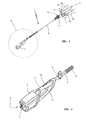
- FIG. 1 shown hand-held implement 1 is a harvester with oscillating moving working tool 2, z. B. rakes that move in the direction of the double arrow 3 about their pivot axes 45.
- the oscillating work tools 2 perform wiper movements about the axes 45.
- the tool movement is generated via a gear 4, which converts the rotational movement of an electric motor M arranged in the transmission housing into an oscillating movement of the working tool 2.
- the transmission 4 with the electric motor is provided at the one end of a guide rod 6 of the working device 1, wherein at the other end of the guide rod 6, a housing 5 with a power source, in the embodiment, a battery pack 11 is provided.
- the battery pack 11 can be accommodated as a replaceable battery pack 11 in a shaft of the housing 5 or consist of firmly provided in the housing 5 single cells.
- the user holds and guides the implement 1 via a handle 5 formed on the housing 5 and a handle portion 8 on the guide rod 6. It may be appropriate, the implement 1 via an attached to the guide rod 6 eyelet 9 on a support belt, a support beam or the like to mount.
- Fig. 1 In the illustrated embodiment according to Fig. 1 is in the housing 5, the power source 10 for the electric motor M ( Fig. 3 ), in the embodiment of the battery pack 11 inserted, the - as in particular Fig. 2 shows - is substantially completely absorbed in the housing 5 of the implement 1.
- a power switch 18 ( Fig. 3 ), which may be formed as a potentiometer, micro-switch or the like .
- the operation switch 18 ( Fig. 3 ) is to operate via a throttle-like actuator 12.
- the actuator 12 is secured via an actuating lock 13, after the depression of which the actuator 12 and provided in the handle 7 operating switch 18 can be actuated.
- the control of the electric motor M is in Fig. 3 illustrated by the example of an electronically commutated motor (EC motor) with a Anberichtmaschine 14.
- EC motor electronically commutated motor
- DC motor brush-driven DC motor
- z. B. an H-bridge to reverse the direction of rotation can be used.
- the electronically commutated electric motor M is controlled via a drive bridge 14 pulse width modulated (PWM).
- PWM pulse width modulated
- the drive bridge 14 consists essentially of three parallel branches 15, 16 and 17, in each of which two series-connected electronic switches 25, 35; 26, 36; 27, 37 are provided. Between the electronic switches 25 and 35, 26 and 36 and 27 and 37, respectively, the voltage tap for the phases U, V and W of the electronically commutated electric motor M (EC motor) is provided.
- the electronic switches 25, 26, 27 and 35, 36, 37 are preferably power transistors, in particular MOSFETs or the like. Electronic components.
- the electronic switches 25, 26, 27, 35, 36, 37 of the drive bridge 14 are driven by a drive circuit 20, wherein the drive circuit 20 includes a microprocessor 21, which in dependence on the position of the rotor of the electric motor M, the associated electronic switch 25, 26, 27, 35, 36, 37 operated.
- the microprocessor 21 of the drive circuit 20 Via a signal line 19, the microprocessor 21 of the drive circuit 20, the mechanical position of the operating switch 18 and thus its transmission is transmitted, whereupon the drive circuit 20 is provided as a main switch 38 in the circuit 39 MOSFET turns on and the supply voltage U V of the battery pack 11 aufschaltet on the drive bridge 14 , Thereafter, the drive bridge 14 is put into operation and the electric motor M started in a selected direction of rotation right or left around.
- the main switch 38 may also be formed as a mechanical switch, which is directly switched by depression of an actuator by the user.
- a capacitor 22 is also connected, which is preferably an electrolytic capacitor.
- the capacitor 22 serves the system as an energy store, which smoothes a peak current load of the battery pack 11 that occurs due to the PWM drive.
- the drive circuit 20 includes a control device 30 for operating the electric motor M in a predetermined direction of rotation, ie, either clockwise in the direction of rotation L or clockwise in the direction of rotation R.
- the direction of rotation L, R of the electric motor M is selected by the control device 30 as a function of the value of a control variable 31, as shown by way of example in FIG Fig. 5 is reproduced.
- the control variable 31 changes between two predetermined values, for. Between the binary values "0" and "1".
- a first value of the control variable 31 is assigned to a first direction of rotation of the electric motor M and a second value of the control variable 31 to a second direction of rotation of the electric motor M.
- the direction of rotation "right” is assigned to the first value “0” and the direction of rotation "left” to the second value “1” ( Fig. 5 ).
- the value "0" or "1" of the control variable 31 is stored in a memory 33, which is preferably provided in the drive circuit 20.
- the operation of the operating switch 18 is communicated via the signal line 19 to the microprocessor 21 of the control circuit 20.
- the microprocessor 21 turns off the MOSFET main switch 38.
- the integrated in the embodiment of the microprocessor 21 control device 30 queries via the signal line 32 from the value of the control variable 31, which is stored in the memory 33. Is z. For example, if a "0" is stored, the controller 30 will set the direction "right". The predetermined running direction "right” is converted by the microprocessor 21 of the drive circuit 20 by the electric motor M in the direction "right” is put into operation via the drive bridge 14. The implement is in operating condition.
- control variable 31 changes its value in a time window after starting the electric motor M and before a restart of the electric motor M.
- This can be z. B. such that the microprocessor 21 randomly changes the value stored in the memory 33 of the control variable.
- a corresponding random generator may be provided in the microprocessor 21 and outputs a value which is stored in the memory 33.
- the electric motor M When the operating switch 18 opens, the electric motor M is actively or passively stopped by the drive circuit 20.
- the microprocessor 21 again queries the value of the memory 33; if the value is "0", again a start in the right direction of rotation takes place; if, on the other hand, a value "1" is stored in the memory 33, the electric motor M is put into operation counterclockwise by the drive circuit 20.
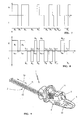
- This change of the operating cycles B 1 , B 2 , ??, B n-1 , B n is in the Fig. 7 schematically represented, where n is any natural number.
- the electric motor is operated clockwise in the direction of rotation; in the operating cycles B 2 , B 4 , B 6 , B 8 , and B 2n the electric motor is operated in the direction of rotation to the left.
- the direction of rotation is inverted, ie the direction of rotation L and R periodically changed.
- the query of the value of the control variable 31 occurs at the latest shortly before starting the electric motor M.
- the engine is initially off or is in standby.
- the electric motor is then started, that is, put into operation in one or the other direction of rotation by the control device 30 as a function of the value of the control variable 31.
- the engine is running (arrow B).
- the electric motor M can be actively or passively brought to a standstill via the drive circuit 20 (arrow C);
- the change or the change of the value of the control variable 31 can be made in the time window from the beginning of the arrow B to the tip of the arrow A, ie from the start of the electric motor M until the start of the electric motor M.
- the mechanical actuation of the operating switch 18 is communicated to the microprocessor 21 via the signal line 19.
- the value of the control variable 31 can be changed.
- the microprocessor 21 may write a new value of the control quantity to the memory 33.
- the microprocessor 21 Upon a first actuation of the operating switch 18, the microprocessor 21 z. For example, a "1" in the memory 33 from; when the operating switch 18 is pressed again, the microprocessor 21 stores the value "0" in the memory 33.
- the value of the control variable changes with each actuation of the operating switch 18, so that, for example, given a first actuation of the operating switch 18 and starting of the electric motor M, the direction of rotation R (right) is given. Since the value of the control variable 31 is read out only directly at the start of the electric motor M, it can come during operation of the implement 1 when the electric motor M even with a change in the value of the control variable 31 to no reversal of the direction of the electric motor M. Only with a second actuation of the operating switch 18 and starting the electric motor M, the inverted rotational direction L (left) is executed. In a third actuation of the operating switch 18 for starting the electric motor M, this in turn rotates clockwise.
- the value of the control variable in dependence on a comparison of the transit times t R , t L of the electric motor M in the one direction of rotation and in the other direction of rotation is changed.
- the transit time t R of the clockwise-rotating electric motor M is added up in a summing element 41.
- the running time t L of the left-handed electric motor is summed in a summing element 42.
- the output signals of the summers 41 and 42 are supplied to a comparator 40, which is designed so that either "0" or "1" is output as the output signal. Is z. B.
- the control variable 31 is thus set to the value "1", so that when the electric motor M is started again, the electric motor is put into operation counterclockwise, since the value "1" is assigned to the control variable 31 in the exemplary embodiment of the "left" direction of rotation. If the motor now rotates in the direction of rotation to the left, the summing element 42 will show a greater output signal than the summing element 41 after a certain transit time; the output signal of the comparator changes to "0".
- the control variable 31 is set to the value "0", so that when the electric motor M is restarted, it is now started in a dextrorotatory manner as a function of the control variable 31.
- the change in the direction of rotation thus achieved is thus dependent on the sums of the transit times in one or the other direction of rotation L, R.
- FIG Fig. 8 This is illustrated in FIG Fig. 8 in which the operating cycles are shown with their times t R1 , t R2 to t Rn-1 , t Rn and t L1 , t L2 to t Ln-1 , t Ln .
- the operating cycles in Fig. 8 are chosen arbitrarily, are thus an example of a random value of the control variable 31.
- the change of the value of the control variable 31 can also be carried out on the basis of the power consumption of the electric motor M in one direction and in the other direction of rotation.
- Fig. 4 is the recorded electric power of the electric motor M in the one direction of rotation R and the recorded electrical power of the electric motor in the other direction of rotation L summed in summers 41 and 42 and fed to a comparator 40. Is z. B.
- the comparator 40 changes the value of the control variable in "1"; If the output quantity of the summing element 41 (clockwise rotation) is smaller than the output value of the summing element 42 (left-hand rotation), the comparator 40 changes the value of the control variable to "0".
- the in Fig. 3 The memory 33 shown in the drive circuit 20 may be expediently provided within the microprocessor 21, wherein the memory may be in particular a volatile memory, that is, that in the currentless drive circuit 20, the stored value of the control variable 31 is lost.
- the control device 30 expediently integrated in the microprocessor 21 queries the value of the control variable 31; Since the memory 33 is cleared or contains an undefined memory contents, the electric motor M starts in an impressed, predetermined direction of rotation, for. To the right.
- a predetermined value of the control variable 31 can be written in the memory 33; the memory 33 is initialized in this way.
- the written in the memory 33 value of the control variable 31 sets z. B. after a change of the battery pack 11 to be executed at the first start of the electric motor M rotational direction L or R firmly.
- the memory 33 can also be designed, for example, as a flash memory, as an EPROM, as an EEPROM, as an FRAM, as a DRAM or the like.
- a further embodiment of the invention can be provided in an electronically commutated electric motor M, the value of the control variable 31 and stored in the memory 33 value of the control variable 31 regardless of switching on and off of the operating switch 18 whenever z. B. one of the electronic switches 25, 26, 27, 35, 36, 37 of the An Kunststoffmaschine 14 is actuated. Although this leads in operation to a repeated change in the value of the control variable, but it results in a simple manner, a random value of the control variable, with over a prolonged use of the implement of the electric motor randomly clockwise or counterclockwise is put into operation. At each restart, the control quantity will have a random value "0" or "1", which will be started correspondingly to the electric motor M right or left. It can be provided that the value of the control variable is only changed when a selected, certain switch 25, 26, 27, 35, 36, 37 of the drive bridge 14 is actuated. One possible sequence of such operating cycles is in Fig. 8 played.
- the drive circuit according to the invention is also in a working device 1 according to Fig. 9 advantageous, which represents a hedge trimmer.
- a battery pack 11 is inserted, the power source 10 ( Fig. 3 ) for a housing 5 arranged in the electric motor M ( Fig. 3 ).
- the electric motor drives a transmission 4 arranged in the housing, which converts the rotational movement of the electric motor into a reciprocating movement of the working tool 2, in the exemplary embodiment of the knife blades 51 and 52, which are moved translationally in the direction of the double arrow 50.
Landscapes
- Engineering & Computer Science (AREA)
- Mechanical Engineering (AREA)
- Life Sciences & Earth Sciences (AREA)
- Environmental Sciences (AREA)
- Power Engineering (AREA)
- Harvester Elements (AREA)
- Control Of Electric Motors In General (AREA)
- Control Of Direct Current Motors (AREA)
- Toys (AREA)
Description
- Die Erfindung betrifft ein handgeführtes Arbeitsgerät mit einem Elektromotor und einer Ansteuerschaltung für den Elektromotor nach dem Oberbegriff des Anspruchs 1.
- Derartige Arbeitsgeräte wie z. B. Olivenemter, Heckenscheren oder dgl. weisen einen Elektromotor auf, dessen drehende Antriebswelle über ein Getriebe ein Arbeitswerkzeug oszillierend antreibt. Das Getriebe setzt dabei die rotatorische Bewegung in eine Hin- und Herbewegung der Arbeitswerkzeuge um.
- Der Elektromotor liegt in einem Stromkreis aus zumindest dem Elektromotor und einem Schalter, über den der Elektromotor an einem Netz oder einem Akkupack in Betrieb genommen wird.
- Es hat sich gezeigt, dass die Umsetzung der drehenden Antriebsbewegung des Elektromotors in eine oszillierende Arbeitsbewegung der Arbeitswerkzeuge das Getriebe belastet und einseitig verschleißt. Um einen Ausfall des Getriebes zu vermeiden, muss dieses entsprechend robust und für die bevorzugte Drehrichtung ausgelegt werden. Dies führt zu einem aufwendigen Getriebe und daher zu einem hohen Gewicht, einer schlechten Ergonomie und einem schlechten Handling des Arbeitsgerätes.
- Der Erfindung liegt die Aufgabe zugrunde, den Verschleiß eines zwischen einem drehenden Elektromotor und einem oszillierenden Arbeitswerkzeug angeordneten Getriebes zu senken.
- Die Aufgabe wird nach den kennzeichnenden Merkmalen des Anspruchs 1 gelöst.
- Es ist eine Steuervorrichtung zum Betrieb des Elektromotors in einer von zwei Drehrichtungen vorgesehen. Die Steuervorrichtung wählt selbstständig ohne direkten Eingriff durch den Benutzer eine der beiden möglichen Drehrichtungen des Elektromotors anhand einer Steuergröße aus, dessen Wert vor dem Start des Elektromotors abgefragt wird. So können z. B. ein erster Wert der Steuergröße einer ersten Drehrichtung des Elektromotors und ein zweiter Wert der Steuergröße einer zweiten Drehrichtung des Elektromotors zugeordnet sein. Wird der Elektromotor gestartet, wird von der Steuervorrichtung die Drehrichtung des Elektromotors bestimmt und der Elektromotor in der ausgewählten Drehrichtung in Betrieb genommen, die dem abgefragten Wert der Steuergröße entspricht.
- Es ist erfindungswesentlich vorgesehen, dass die Steuergröße - nach vorgegebenen Kriterien - vor einem Wiederstart des Elektromotors ihren Wert wechselt, so dass bei einem Wiederstart des Elektromotors in einem folgenden Betriebszyklus ein anderer Wert der Steuergröße vorliegen kann. Liegt ein anderer Wert vor, wird von der Steuervorrichtung eine invertierte Drehrichtung vorgegeben und der Elektromotor in der anderen Drehrichtung in Betrieb genommen. Dadurch wird erreicht, dass die Drehrichtung des Elektromotors über eine längere Betriebszeit des Arbeitsgerätes in den aufeinanderfolgenden Betriebszyklen des Elektromotors wiederholt selbstständig gewechselt ist, so dass das Getriebe nicht nur in einer Drehrichtung belastet wird, sondern in beiden Drehrichtungen belastet wird. Dieses wiederholte Umschalten der Laufrichtung des das Arbeitswerkzeug antreibenden Elektromotors führt zu einem gleichmäßigeren Verschleiß des Getriebes, wodurch sich bei gleicher konstruktiver Auslegung insgesamt längere Standzeiten für das Getriebe selbst ergeben. Dies eröffnet auch die Möglichkeit, einfacher gestaltete Getriebe aus vorzugsweise leichten Materialien einzusetzen, so dass durch Einsparung von Gewicht das Handling und die Ergonomie des Arbeitsgerätes verbessert sind.
- Die Drehrichtungsumkehr des Elektromotors ändert die oszillierende Bewegung (Hin- und Herbewegung, Wischerbewegung, translatorische Bewegung und dgl.) des Arbeitswerkzeuges selbst nicht. Insoweit ergeben sich durch die Drehrichtungsumkehr keine Nachteile bei der Arbeit mit den oszillierenden Arbeitswerkzeugen des Arbeitsgerätes.
- Vorzugsweise ist vorgesehen, dass die Steuergröße in einem Zeitfenster nach dem Starten des Elektromotors und vor einem nächsten Wiederstart des Elektromotors ihren Wert wechselt. Dabei ist insbesondere vorgesehen, dass die Steuergröße zwischen zwei vorgegebenen Werten wechselt, wobei ein erster Wert einer ersten Drehrichtung des Elektromotors (z. B. Rechtslauf) zugeordnet ist und ein zweiter Wert einer zweiten Drehrichtung des Elektromotors (z. B. Linkslauf) zugeordnet ist. Vorteilhaft wechselt die Steuergröße z. B. zwischen den Werten "0" und "1 ", entsprechend der Binärcodierung handelsüblicher Speicher.
- In besonderer Ausgestaltung der Erfindung ist vorgesehen, dass die Steuergröße ihren Wert von einem zum nächsten Betriebszyklus periodisch wechselt, also die Drehrichtung jeweils invertiert wird. Nach einem Betriebszyklus mit rechtsdrehendem Elektromotor folgt ein Betriebszyklus mit linksdrehendem Elektromotor, dem wieder ein Betriebszyklus mit rechtsdrehendem Elektromotor folgt usw..
- In einer einfachen Ausgestaltung kann die Steuergröße ihren Wert zufällig wechseln. Dies kann durch einen einfachen Zufallsgenerator ausgeführt sein, der beispielsweise in der Ansteuerschaltung integriert sein kann. Ein einfacher Zufallsgenerator kann ein im Betrieb des Elektromotors mit einer festen oder variablen Taktfrequenz zählender Zähler sein; bei geradem Zählerstand wird der Elektromotor rechtslaufend gestartet, bei ungeraden Zahlen wird der Elektromotor linkslaufend gestartet. Bereits eine zufällige Drehrichtungsumkehr des antreibenden Elektromotors führt zu einem gleichmäßigeren Verschleiß des Getriebes.
- Vorteilhaft kann bereits aus dem mechanischen Betätigen des Betriebsschalters ein Signal abgeleitet werden, das dazu genutzt wird, den Wert der Steuergröße zu wechseln. Erfolgt der Wechsel der Steuergröße mit jedem Betätigen des Betriebsschalters bzw. Einschalten des Elektromotors, ergibt sich ein periodischer Wechsel der Drehrichtung des Elektromotors.
- In einer bevorzugten Ausführungsform der Erfindung ist vorgesehen, dass der Wert der Steuergröße in Abhängigkeit eines Vergleichs der Laufzeit des Elektromotors in der einen Drehrichtung und der Laufzeit des Elektromotors in der anderen Drehrichtung gewechselt wird. So wird sichergestellt, dass der Motor immer in der Drehrichtung gestartet wird, deren Laufzeit geringer ist.
- Es kann auch zweckmäßig sein, den Wert der Steuergröße in Abhängigkeit eines Vergleichs der vom Elektromotor in der einen Drehrichtung aufgenommenen Leistung und der vom Elektromotor in der anderen Drehrichtung aufgenommenen Leistung zu wechseln. Der Motor wird in der Drehrichtung gestartet, deren aufsummierte aufgenommene Leistung geringer ist. Die in einer Drehrichtung aufsummierten elektrischen Leistungen entsprechen etwa der in dieser Drehrichtung geleisteten Arbeit.
- Zweckmäßig ist vorgesehen, dass der Wert der Steuergröße in einem Speicher der Ansteuerschaltung abgespeichert ist. Der Speicher kann beispielsweise ein EPROM Speicherbaustein oder auch als EEPROM, FRAM, DRAM oder als bistabile oder monostabile Kippstufe (Flipflop) ausgebildet sein.
- Vorteilhaft ist die Steuervorrichtung mit einem Mikroprozessor versehen, wobei der Speicher in dem Mikroprozessor ausgebildet sein kann. Dieser Speicher kann ein flüchtiger Speicher sein, wobei vorgesehen ist, dass der Elektromotor bei gelöschtem Speicher bzw. bei undefiniertem Speicherinhalt in einer eingeprägten, vorgegebenen Drehrichtung gestartet wird. Der Elektromotor läuft somit bei gelöschtem Speicher bzw. bei undefiniertem Speicherinhalt immer in der gleichen Drehrichtung an, z. B. im Rechtslauf.
- Vorteilhaft ist als Energiequelle zum Betrieb des Elektromotors ein im Gehäuse des Arbeitsgerätes aufgenommener Akkupack vorgesehen.
- Weitere Merkmale der Erfindung ergeben sich aus den weiteren Ansprüchen, der Beschreibung und Zeichnung, in der ein nachfolgend im Einzelnen beschriebenes Ausführungsbeispiel der Erfindung dargestellt ist. Es zeigen:
- Fig. 1
- eine perspektivische Ansicht eines Erntewerkzeuges,
- Fig. 2
- eine vergrößerte Ansicht des Details II in
Fig. 1 , - Fig. 3
- eine schematische Darstellung einer Ansteuerschaltung für einen elektronisch kommutierten Elektromotor,
- Fig. 4
- eine schematische Darstellung einer Vergleichsschaltung zur Auswertung der Laufzeiten in der einen und der anderen Drehrichtung des Elektromotors,
- Fig. 5
- ein Ausgangssignal der Vergleichsschaltung nach
Fig. 4 , - Fig. 6
- ein Ablaufdiagramm zum Betrieb des Elektromotors,
- Fig. 7
- ein Schaubild der über eine Zeitachse aufgetragenen Betriebszyklen,
- Fig. 8
- ein Schaubild der über eine Zeitachse aufgetragenen Betriebszeiten,
- Fig. 9
- eine perspektivische Ansicht eines weiteren Arbeitsgerätes am Beispiel einer Heckenschere.
- Das in
Fig. 1 dargestellte handgeführte Arbeitsgerät 1 ist ein Erntegerät mit oszillierend bewegten Arbeitswerkzeug 2, z. B. Rechen, die sich in Richtung des Doppelpfeils 3 um ihre Anlenkachsen 45 bewegen. Die oszillierenden Arbeitswerkzeuge 2 führen Wischerbewegungen um die Achsen 45 aus. Die Werkzeugbewegung wird über ein Getriebe 4 erzeugt, welches die Drehbewegung eines im Getriebegehäuse angeordneten Elektromotors M in eine oszillierende Bewegung des Arbeitswerkzeugs 2 umsetzt. Das Getriebe 4 mit dem Elektromotor ist an dem einen Ende einer Führungsstange 6 des Arbeitsgeräts 1 vorgesehen, wobei an dem anderen Ende der Führungsstange 6 ein Gehäuse 5 mit einer Energiequelle, im Ausführungsbeispiel ein Akkupack 11 vorgesehen ist. Der Akkupack 11 kann als auswechselbarer Akkupack 11 in einem Schacht des Gehäuses 5 aufgenommen sein oder auch aus fest im Gehäuse 5 vorgesehenen Einzelzellen bestehen. - Der Benutzer hält und führt das Arbeitsgerät 1 über einen am Gehäuse 5 ausgebildeten Handgriff 7 sowie einen Griffbereich 8 an der Führungsstange 6. Es kann zweckmäßig sein, das Arbeitsgerät 1 über eine an der Führungsstange 6 befestigte Öse 9 an einem Traggurt, einem Tragbaum oder dgl. einzuhängen.
- Im gezeigten Ausführungsbeispiel nach
Fig. 1 ist im Gehäuse 5 die Energiequelle 10 für den Elektromotor M (Fig. 3 ), im Ausführungsbeispiel der Akkupack 11 eingeschoben, der - wie insbesondereFig. 2 zeigt - im Wesentlichen vollständig im Gehäuse 5 des Arbeitsgerätes 1 aufgenommen ist. - Im Handgriff 7 ist ein Betriebsschalter 18 (
Fig. 3 ) angeordnet, der als Potentiometer, Mikroschalter oder dgl. ausgebildet sein kann. Der Betriebsschalter 18 (Fig. 3 ) ist über ein gashebelähnliches Betätigungsglied 12 zu bedienen. Das Betätigungsglied 12 ist über eine Betätigungssperre 13 gesichert, nach deren Niederdrücken das Betätigungsglied 12 und der im Handgriff 7 vorgesehene Betriebsschalter 18 betätigt werden können. - Die Ansteuerung des Elektromotors M ist in
Fig. 3 am Beispiel eines elektronisch kommutierten Motors (EC-Motor) mit einer Ansteuerbrücke 14 dargestellt. Alternativ kann auch ein bürstenbetriebener Gleichstrommotor (DC-Motor) mit entsprechend vereinfachter Ansteuerung, z. B. einer H-Brücke zur Drehrichtungsumkehr, verwendet werden. - Im Ausführungsbeispiel wird der elektronisch kommutierte Elektromotor M über eine Ansteuerbrücke 14 pulsweitenmoduliert (PWM) angesteuert. Die Ansteuerbrücke 14 besteht im Wesentlichen aus drei Parallelzweigen 15, 16 und 17, in denen jeweils zwei in Reihe geschaltete elektronische Schalter 25, 35; 26, 36; 27, 37 vorgesehen sind. Zwischen den elektronischen Schaltern 25 und 35, 26 und 36 und 27 und 37 ist jeweils der Spannungsabgriff für die Phasen U, V und W des elektronisch kommutierten Elektromotors M (EC-Motor) vorgesehen.
- Die elektronischen Schalter 25, 26, 27 bzw. 35, 36, 37 sind bevorzugt Leistungstransistoren, insbesondere MOSFET's oder dgl. elektronische Bauelemente.
- Die elektronischen Schalter 25, 26, 27, 35, 36, 37 der Ansteuerbrücke 14 werden von einer Ansteuerschaltung 20 angesteuert, wobei die Ansteuerschaltung 20 einen Mikroprozessor 21 umfasst, der in Abhängigkeit von der Stellung des Rotors des Elektromotors M die zugeordneten elektronischen Schalter 25, 26, 27, 35, 36, 37 betätigt.
- Über eine Signalleitung 19 wird dem Mikroprozessor 21 der Ansteuerschaltung 20 die mechanische Stellung des Betriebsschalters 18 und somit dessen Betätigung übermittelt, worauf die Ansteuerschaltung 20 einen als Hauptschalter 38 im Stromkreis 39 vorgesehenen MOSFET durchschaltet und die Versorgungsspannung UV des Akkupacks 11 auf die Ansteuerbrücke 14 aufschaltet. Danach wird die Ansteuerbrücke 14 in Betrieb genommen und der Elektromotor M in eine ausgewählte Drehrichtung rechts oder links herum gestartet.
- Der Hauptschalter 38 kann auch als mechanischer Schalter ausgebildet sein, der durch Niederdrücken eines Betätigungsgliedes vom Benutzer unmittelbar geschaltet wird.
- Parallel zur Ansteuerbrücke 14 ist ferner ein Kondensator 22 geschaltet, der bevorzugt ein Elektrolytkondensator ist. Der Kondensator 22 dient dem System als Energiespeicher, der eine aufgrund der PWM-Ansteuerung auftretende Spitzenstrombelastung des Akkupacks 11 glättet.
- Die Ansteuerschaltung 20 umfasst eine Steuervorrichtung 30 zum Betrieb des Elektromotors M in einer vorgegebenen Drehrichtung, also entweder in der Drehrichtung L linkslaufend oder in der Drehrichtung R rechtslaufend. Die Drehrichtung L, R des Elektromotors M wird von der Steuervorrichtung 30 in Abhängigkeit des Wertes einer Steuergröße 31 gewählt, wie sie beispielhaft in
Fig. 5 wiedergegeben ist. Im gezeigten Ausführungsbeispiel wechselt die Steuergröße 31 zwischen zwei vorgegebenen Werten, z. B. zwischen den binären Werten "0" und "1 ". - Ein erster Wert der Steuergröße 31 ist einer ersten Drehrichtung des Elektromotors M und ein zweiter Wert der Steuergröße 31 einer zweiten Drehrichtung des Elektromotors M zugeordnet. Im gezeigten Ausführungsbeispiel nach
Fig. 5 ist dem ersten Wert "0" die Drehrichtung "rechts" und dem zweiten Wert "1" die Drehrichtung "links" zugeordnet (Fig. 5 ). Im gezeigten Ausführungsbeispiel ist ferner vorgesehen, dass der Wert "0" oder "1" der Steuergröße 31 in einem Speicher 33 abgelegt ist, der bevorzugt in der Ansteuerschaltung 20 vorgesehen ist. - Wird von einem Benutzer das Arbeitsgerät 1 durch Niederdrücken des Betätigungsgliedes 12 und somit durch Einschalten des Betriebsschalters 18 in Betrieb genommen, so wird die Betätigung des Betriebsschalters 18 über die Signalleitung 19 dem Mikroprozessor 21 der Ansteuerschaltung 20 mitgeteilt. Der Mikroprozessor 21 schaltet den als MOSFET ausgeführten Hauptschalter 38 durch. Die im Ausführungsbeispiel im Mikroprozessor 21 integrierte Steuervorrichtung 30 fragt über die Signalleitung 32 den Wert der Steuergröße 31 ab, die im Speicher 33 gespeichert ist. Ist z. B. eine "0" gespeichert, wird die Steuervorrichtung 30 die Laufrichtung "rechts" vorgeben. Die vorgegebene Laufrichtung "rechts" wird vom Mikroprozessor 21 der Ansteuerschaltung 20 umgesetzt, indem über die Ansteuerbrücke 14 der Elektromotor M in der Laufrichtung "rechts" in Betrieb genommen wird. Das Arbeitsgerät ist im Betriebszustand.
- Es ist vorgesehen, dass die Steuergröße 31 in einem Zeitfenster nach dem Starten des Elektromotors M und vor einem Wiederstart des Elektromotors M ihren Wert wechselt. Dies kann z. B. derart erfolgen, dass der Mikroprozessor 21 den im Speicher 33 abgespeicherten Wert der Steuergröße zufällig wechselt. Ein entsprechender Zufallsgenerator kann im Mikroprozessor 21 vorgesehen sein und gibt einen Wert aus, der im Speicher 33 abgespeichert wird.
- Öffnet der Betriebsschalter 18, wird der Elektromotor M von der Ansteuerschaltung 20 aktiv oder passiv gestoppt. Bei einem Wiederstart des Elektromotors M fragt der Mikroprozessor 21 erneut den Wert des Speichers 33 ab; ist der Wert "0", erfolgt wiederum ein Start in rechter Drehrichtung; ist hingegen im Speicher 33 ein Wert "1" abgespeichert, wird der Elektromotor M von der Ansteuerschaltung 20 linksdrehend in Betrieb genommen.
- Dieser Wechsel der Betriebszyklen B1, B2,....., Bn-1, Bn, ist in den
Fig. 7 schematisch wiedergegeben, wobei n eine beliebige natürliche Zahl ist. In den Betriebszyklen B1, B3, B5, B7, und B2n+1 ist der Elektromotor in Drehrichtung rechts betrieben; in den Betriebszyklen B2, B4, B6, B8, und B2n ist der Elektromotor in Drehrichtung links betrieben. NachFig. 7 wird nach jedem Stopp des Elektromotors M die Drehrichtung invertiert, also die Drehrichtung L und R periodisch gewechselt. - In der Darstellung nach
Fig. 8 erfolgt der Wechsel der Betriebszyklen nicht mit jedem Stopp des Elektromotors M, sondern nach anderen - auch zufälligen - Kriterien. Allgemein gilt, dass nach einem ersten Betriebszyklus Bn der Wechsel der Drehrichtung im folgenden Betriebszyklus Bn+x erfolgt, wobei x eine beliebige natürliche Zahl sein kann. Die Drehrichtungsumkehr kann also erst nach dem zweiten oder dritten Betriebszyklus Bn+2 bzw. Bn+3 erfolgen, wie inFig. 7 dargstellt ist. - Bereits ein zufälliger, wiederholter Wechsel der Drehrichtung des Elektromotors M des Arbeitsgeräts führt zu einer gleichmäßigeren Belastung des Getriebes 4, welches die Drehbewegung in eine oszillierende Bewegung der Arbeitswerkzeuge 2 umsetzt. Dadurch kann die Lebensdauer des Getriebes 4 bei ansonsten unveränderter Konstruktion signifikant gesteigert werden.
- Die Abfrage des Wertes der Steuergröße 31 erfolgt spätestens kurz vor dem Starten des Elektromotors M. Wie in
Fig. 6 dargestellt, ist der Motor zunächst aus bzw. steht im Standby. In Richtung des Pfeils A gehend wird der Elektromotor dann gestartet, also von der Steuervorrichtung 30 in Abhängigkeit des Wertes der Steuergröße 31 in die eine oder andere Drehrichtung in Betrieb genommen. Der Motor läuft (Pfeil B). Der Elektromotor M kann über die Ansteuerschaltung 20 aktiv oder passiv zum Stillstand gebracht werden (Pfeil C); der Elektromotor steht und hat seinen Ausgangszustand "Motor aus" eingenommen (Pfeil D). Die Änderung bzw. der Wechsel des Wertes der Steuergröße 31 kann in dem Zeitfenster von Beginn des Pfeils B bis zur Spitze des Pfeils A vorgenommen werden, also vom Start des Elektromotors M bis zum Wiederstart des Elektromotors M. - Im Ausführungsbeispiel nach
Fig. 3 ist gezeigt, dass über die Signalleitung 19 die mechanische Betätigung des Betriebsschalters 18 dem Mikroprozessor 21 mitgeteilt ist. Mit jedem Betätigen des Betriebsschalters 18 kann der Wert der Steuergröße 31 gewechselt werden. Immer dann, wenn der Betriebsschalter 18 eingeschaltet wird, kann der Mikroprozessor 21 einen neuen Wert der Steuergröße in den Speicher 33 schreiben. Bei einem ersten Betätigen des Betriebsschalters 18 legt der Mikroprozessor 21 z. B. eine "1" im Speicher 33 ab; bei einem erneuten Betätigen des Betriebsschalters 18 legt der Mikroprozessor 21 den Wert "0" im Speicher 33 ab. Dadurch ändert sich der Wert der Steuergröße mit jedem Betätigen des Betriebsschalters 18, so dass z.B. bei einem ersten Betätigen des Betriebsschalters 18 und Starten des Elektromotors M die Drehrichtung R (rechts) gegeben ist. Da der Wert der Steuergröße 31 nur direkt beim Start des Elektromotors M ausgelesen wird, kann es im Betrieb des Arbeitsgerätes 1 bei laufendem Elektromotor M auch bei einem Wechsel des Wertes der Steuergröße 31 zu keiner Drehrichtungsumkehr des Elektromotors M kommen. Erst bei einem zweiten Betätigen des Betriebsschalters 18 und Starten des Elektromotors M wird die invertierte Drehrichtung L (links) ausgeführt. Bei einem dritten Betätigen des Betriebsschalters 18 zum Starten des Elektromotors M dreht dieser wiederum rechts herum. Es erfolgt ein periodisches, jeweils invertiertes Umschalten der Laufrichtung des Elektromotors M in den unmittelbar aufeinanderfolgenden Betriebszyklen B1, B2, B3,....., Bn-1, Bn, wie dies inFig. 7 wiedergegeben ist. Der Elektromotor startet jeweils in einer anderen, invertierten Drehrichtung R bzw. L. - In einem in
Fig. 4 dargestellten Ausführungsbeispiel wird der Wert der Steuergröße in Abhängigkeit eines Vergleichs der Laufzeiten tR, tL des Elektromotors M in der einen Drehrichtung und in der anderen Drehrichtung gewechselt. Die Laufzeit tR des rechtsdrehenden Elektromotors M wird in einem Summierglied 41 aufaddiert. Entsprechend wird die Laufzeit tL des linksdrehenden Elektromotors in einem Summierglied 42 aufsummiert. Die Ausgangssignale der Summierglieder 41 und 42 werden einem Vergleicher 40 zugeführt, der so ausgelegt ist, dass als Ausgangssignal entweder eine "0" oder eine "1" ausgegeben wird. Ist z. B. die ausgegebene Größe des Summiergliedes 41 (Rechtslauf) größer als die ausgegebene Größe des Summiergliedes 42 (Linkslauf), so gibt der Vergleicher 40 den Wert "1" aus. EntsprechendFig. 5 wird die Steuergröße 31 somit auf den Wert "1" gesetzt, so dass bei einem erneuten Start des Elektromotors M der Elektromotor linksdrehend in Betrieb genommen wird, da der Wert "1" der Steuergröße 31 im Ausführungsbeispiel der Drehrichtung "links" zugeordnet ist. Dreht der Motor nun in Drehrichtung links, wird nach einer bestimmten Laufzeit das Summierglied 42 ein größeres Ausgangssignal zeigen als das Summierglied 41; das Ausgangssignal des Vergleichers wechselt auf "0". Die Steuergröße 31 wird auf den Wert "0" gesetzt, so dass bei einem Wiederstart des Elektromotors M dieser nun in Abhängigkeit von der Steuergröße 31 rechtsdrehend gestartet wird. - Der dadurch erzielte Wechsel der Drehrichtung ist somit abhängig von den Summen der Laufzeiten in die eine oder in die andere Drehrichtung L, R. Beispielhaft ist dies in
Fig. 8 wiedergegeben, in der die Betriebszyklen mit ihren Zeiten tR1, tR2 bis tRn-1, tRn und tL1, tL2 bis tLn-1, tLn wiedergegeben sind. Die Betriebszyklen inFig. 8 sind willkürlich gewählt, sind somit ein Beispiel für einen zufälligen Wert der Steuergröße 31. - Zweckmäßig kann der Wechsel des Wertes der Steuergröße 31 auch anhand der Leistungsaufnahme des Elektromotors M in der einen und in der anderen Drehrichtung ausgeführt werden. Entsprechend der Darstellung in
Fig. 4 wird die aufgenommene elektrische Leistung des Elektromotors M in der einen Drehrichtung R und die aufgenommene elektrische Leistung des Elektromotors in der anderen Drehrichtung L in Summiergliedern 41 und 42 aufsummiert und einem Vergleicher 40 zugeführt. Ist z. B. die ausgegebene Größe des Summiergliedes 41 (Rechtslauf) größer als die ausgegebene Größe des Summiergliedes 42 (Linkslauf), so wechselt der Vergleicher 40 den Wert der Steuergröße in "1 "; ist die ausgegebene Größe des Summiergliedes 41 (Rechtslauf) kleiner als die ausgegebene Größe des Summiergliedes 42 (Linkslauf), so wechselt der Vergleicher 40 den Wert der Steuergröße in "0". - Der in
Fig. 3 in der Ansteuerschaltung 20 gezeigte Speicher 33 kann zweckmäßig innerhalb des Mikroprozessors 21 vorgesehen sein, wobei der Speicher insbesondere ein flüchtiger Speicher sein kann, d. h., dass bei stromloser Ansteuerschaltung 20 der gespeicherte Wert der Steuergröße 31 verloren geht. Bei einem Wiederstart fragt die zweckmäßig im Mikroprozessor 21 integrierte Steuervorrichtung 30 den Wert der Steuergröße 31 ab; da der Speicher 33 gelöscht ist oder einen undefinierten Speicherinhalt enthält, startet der Elektromotor M in einer eingeprägten, vorgegebenen Drehrichtung, z. B. rechts herum. Bei der ersten Bestromung der Ansteuerschaltung 20 kann ein vorgegebener Wert der Steuergröße 31 in den Speicher 33 geschrieben werden; der Speicher 33 wird so initialisiert. Der in den Speicher 33 eingeschriebene Wert der Steuergröße 31 legt z. B. nach einem Wechsel des Akkupacks 11 die beim ersten Start des Elektromotors M auszuführende Drehrichtung L oder R fest. - Der Speicher 33 kann beispielsweise auch als Flash-Speicher, als EPROM-Speicher, als EEPROM, als FRAM, als DRAM oder dgl. ausgebildet sein.
- In einer weiteren Ausführungsform der Erfindung kann vorgesehen sein, bei einem elektronisch kommutierten Elektromotor M den Wert der Steuergröße 31 bzw. den im Speicher 33 abgespeicherten Wert der Steuergröße 31 unabhängig vom Ein- und Ausschalten des Betriebsschalters 18 immer dann zu wechseln, wenn z. B. einer der elektronischen Schalter 25, 26, 27, 35, 36, 37 der Ansteuerbrücke 14 betätigt wird. Dies führt im Betrieb zwar zu einem wiederholten Wechseln des Wertes der Steuergröße, es ergibt sich aber in einfacher Weise ein zufälliger Wert der Steuergröße, wobei über eine längere Nutzung des Arbeitsgerätes der Elektromotor zufällig rechtslaufend oder linkslaufend in Betrieb genommen wird. Bei jedem Wiederstart wird die Steuergröße einen zufälligen Wert "0" oder "1" haben, dem entsprechend der Elektromotor M rechts oder links herum gestartet wird. Dabei kann vorgesehen sein, dass der Wert der Steuergröße nur dann gewechselt wird, wenn ein ausgewählter, bestimmter Schalter 25, 26, 27, 35, 36, 37 der Ansteuerbrücke 14 betätigt wird. Ein möglicher Ablauf derartiger Betriebszyklen ist in
Fig. 8 wiedergegeben. - Die erfindungsgemäße Ansteuerschaltung ist auch bei einem Arbeitsgerät 1 nach
Fig. 9 vorteilhaft, welches eine Heckenschere darstellt. Im Gehäuse 5 des Arbeitsgerätes 1 ist wiederum ein Akkupack 11 eingeschoben, der die Energiequelle 10 (Fig. 3 ) für einen im Gehäuse 5 angeordneten Elektromotor M (Fig. 3 ) bildet. Der Elektromotor treibt ein im Gehäuse angeordnetes Getriebe 4 an, welches die Drehbewegung des Elektromotors in eine Hin- und Herbewegung des Arbeitswerkzeugs 2, im Ausführungsbeispiel der Messerblätter 51 und 52 umsetzt, die in Richtung des Doppelpfeils 50 translatorisch bewegt werden.
Claims (13)
- Handgeführtes Arbeitsgerät (1) mit einem Elektromotor (M) und mit einer Ansteuerschaltung (20) für den Elektromotor (M), wobei der Elektromotor (M) über ein Getriebe (4) ein Arbeitswerkzeug (2) antreibt, und die Drehbewegung des Elektromotors (M) über das Getriebe (4) in eine oszillierende Bewegung des Arbeitswerkzeugs (2) umgewandelt ist, und mit einem Stromkreis (39) aus zumindest dem Elektromotor (M) und einem Schalter (25, 26, 27, 35, 36, 37, 38) zum Betrieb des Elektromotors (M) in einer Drehrichtung,
dadurch gekennzeichnet, dass in der Ansteuerschaltung (20) eine Steuervorrichtung (30) zum Betrieb des Elektromotors (M) in einer von zwei Drehrichtungen vorgesehen ist, dass die Steuervorrichtung (30) in Abhängigkeit einer Steuergröße (31) selbstständig eine ausgewählte Drehrichtung des Elektromotors (M) für einen nächsten Betriebszyklus (Bn) bestimmt und bei Start des Elektromotors (M) der Elektromotor (M) in der einem Wert der Steuergröße (31) zugeordneten Drehrichtung gestartet wird, und dass der Wert der Steuergröße (31) für einen folgenden Betriebszyklus (Bn+x) selbstständig neu bestimmt wird. - Arbeitsgerät nach Anspruch 1,
dadurch gekennzeichnet, dass der Wert der Steuergröße (31) in einem Zeitfenster nach dem Start des Elektromotors (M) und vor einem nächsten Wiederstart des Elektromotors (M) neu bestimmt wird. - Arbeitsgerät nach Anspruch 1 oder 2,
dadurch gekennzeichnet, dass der Wert der Steuergröße (31) zwischen einem einer ersten Drehrichtung des Elektromotors (M) zugeordneten ersten Wert und einem einer zweiten Drehrichtung des Elektromotors (M) zugeordnet zweiten Wert wechselt. - Arbeitsgerät nach einem der Ansprüche 1 bis 3,
dadurch gekennzeichnet, dass die Steuergröße (31) ihren Wert von einem zum nächsten Betriebszyklus(Bn, Bn+1) periodisch wechselt. - Arbeitsgerät nach einem der Ansprüche 1 bis 3,
dadurch gekennzeichnet, dass der Wert der Steuergröße (31) zufällig neu bestimmt wird. - Arbeitsgerät nach einem der Ansprüche 1 bis 3,
dadurch gekennzeichnet, dass der Wert der Steuergröße (31) durch mechanisches Betätigen eines Betriebsschalters (18) zur Inbetriebnahme des Elektromotors (M) neu bestimmt wird. - Arbeitsgerät nach einem der Ansprüche 1 bis 3,
dadurch gekennzeichnet, dass der Wert der Steuergröße (31) in Abhängigkeit eines Vergleichs der Laufzeit (tR) des Elektromotors in der einen Drehrichtung und der Laufzeit (tL) des Elektromotors in der anderen Drehrichtung neu bestimmt wird. - Arbeitsgerät nach einem der Ansprüche 1 bis 3,
dadurch gekennzeichnet, dass der Wert der Steuergröße (31) in Abhängigkeit eines Vergleichs der aufgenommenen Leistung des Elektromotors (M) in der einen Drehrichtung und der aufgenommenen Leistung des Elektromotors (M) in der anderen Drehrichtung neu bestimmt wird. - Arbeitsgerät nach einem der Ansprüche 1 bis 8,
dadurch gekennzeichnet, dass der Wert der Steuergröße (31) in einem Speicher (33) abgespeichert ist. - Arbeitsgerät nach Anspruch 9,
dadurch gekennzeichnet, dass die Steuervorrichtung (30) einen Mikroprozessor (21) aufweist und der Speicher (33) in dem Mikroprozessor (21) vorgesehen ist. - Arbeitsgerät nach Anspruch 9 oder 10,
dadurch gekennzeichnet, dass der Speicher (33) ein flüchtiger Speicher ist. - Arbeitsgerät nach einem der Ansprüche 9 bis 11,
dadurch gekennzeichnet, dass bei gelöschtem Speicher (33) mit undefiniertem Speicherinhalt die Steuervorrichtung (30) den Elektromotor (M) in einer vorgegebenen Drehrichtung startet. - Arbeitsgerät nach einem der Ansprüche 1 bis 12,
dadurch gekennzeichnet, dass als Energiequelle zum Betrieb des Elektromotors (M) ein Akkupack vorgesehen ist.
Applications Claiming Priority (1)
| Application Number | Priority Date | Filing Date | Title |
|---|---|---|---|
| DE102012017963.4A DE102012017963A1 (de) | 2012-09-12 | 2012-09-12 | Handgeführtes Arbeitsgerät mit einer Ansteuerschaltung für einen oszillierende Werkzeuge antreibenden Elektromotor |
Publications (3)
| Publication Number | Publication Date |
|---|---|
| EP2709269A2 true EP2709269A2 (de) | 2014-03-19 |
| EP2709269A3 EP2709269A3 (de) | 2016-12-14 |
| EP2709269B1 EP2709269B1 (de) | 2018-11-07 |
Family
ID=49182036
Family Applications (1)
| Application Number | Title | Priority Date | Filing Date |
|---|---|---|---|
| EP13004331.8A Active EP2709269B1 (de) | 2012-09-12 | 2013-09-04 | Handgeführtes arbeitsgerät mit einer ansteuerschaltung für einen oszillierende werkzeuge antreibenden elektromotor |
Country Status (4)
| Country | Link |
|---|---|
| US (1) | US9742315B2 (de) |
| EP (1) | EP2709269B1 (de) |
| CN (1) | CN103684145B (de) |
| DE (1) | DE102012017963A1 (de) |
Cited By (2)
| Publication number | Priority date | Publication date | Assignee | Title |
|---|---|---|---|---|
| EP3213875A1 (de) * | 2016-03-04 | 2017-09-06 | HILTI Aktiengesellschaft | Elektrische handwerkzeugmaschine und kalibrierungsverfahren |
| EP4437829A1 (de) * | 2023-03-27 | 2024-10-02 | Cifarelli S.p.A. | Tragbares landwirtschaftliches werkzeug |
Families Citing this family (5)
| Publication number | Priority date | Publication date | Assignee | Title |
|---|---|---|---|---|
| US9798521B2 (en) * | 2014-08-27 | 2017-10-24 | Schlage Lock Company Llc | System, method and apparatus for random number generation |
| USD813808S1 (en) * | 2016-02-15 | 2018-03-27 | Andreas Stihl Ag & Co. Kg | Battery powered drive unit |
| DE102017202579A1 (de) | 2017-02-17 | 2018-08-23 | Robert Bosch Gmbh | Handwerkzeugmaschine |
| GR20210100329A (el) * | 2021-05-17 | 2022-12-12 | Νικολαος Ιωαννη Χριστοδουλακης | Αυτονομη ελαιοραβδιστικη βεργα με μπαταρια |
| EP4342632A1 (de) * | 2022-09-21 | 2024-03-27 | Guido Valentini | Handgeführtes, motorisch angetriebenes polier- oder schleifwerkzeug |
Family Cites Families (12)
| Publication number | Priority date | Publication date | Assignee | Title |
|---|---|---|---|---|
| US2416229A (en) * | 1944-02-26 | 1947-02-18 | Philco Corp | Control apparatus for reversible motors |
| US4609155A (en) * | 1985-04-09 | 1986-09-02 | Shredding Systems, Inc. | Shredding apparatus including overload protection of drive line |
| JP2936211B2 (ja) * | 1991-07-22 | 1999-08-23 | 自動車機器株式会社 | 電動式動力舵取装置における電流制限方法 |
| EP1213829B1 (de) * | 1996-01-10 | 2004-12-08 | ebm-papst St. Georgen GmbH & Co. KG | Verfahren zum Betreiben eines elektronisch kommutierten Gleichstrommotors, und Motor zur Durchführung eines solchen Verfahrens |
| DE60135166D1 (de) * | 2000-03-16 | 2008-09-11 | Makita Corp | Werkzeugmaschinen |
| JP2005066785A (ja) * | 2003-08-26 | 2005-03-17 | Matsushita Electric Works Ltd | 電動工具 |
| DE202004019853U1 (de) * | 2004-12-15 | 2005-02-24 | C. & E. Fein Gmbh | Maschine zum Schrauben oder Bohren |
| US7573217B2 (en) * | 2005-05-31 | 2009-08-11 | Regal-Beloit Corporation | Methods and systems for automatic rotation direction determination of electronically commutated motor |
| EP1969919B1 (de) * | 2007-03-14 | 2012-01-18 | Robert Bosch Gmbh | Schneidgerät oder Heckenschere |
| DE602007005796D1 (de) * | 2007-08-22 | 2010-05-20 | Bosch Gmbh Robert | Schneidegerät |
| US20100300163A1 (en) * | 2009-05-29 | 2010-12-02 | Stanton Concepts Inc. | A Combination Lock Having Wheels with A Plurality Of Cams |
| WO2012010190A1 (en) * | 2010-07-19 | 2012-01-26 | Gardena Manufacturing Gmbh | Electric power tool with alternating starting direction |
-
2012
- 2012-09-12 DE DE102012017963.4A patent/DE102012017963A1/de not_active Withdrawn
-
2013
- 2013-09-04 EP EP13004331.8A patent/EP2709269B1/de active Active
- 2013-09-12 US US14/025,729 patent/US9742315B2/en active Active
- 2013-09-12 CN CN201310414279.3A patent/CN103684145B/zh active Active
Non-Patent Citations (1)
| Title |
|---|
| None |
Cited By (3)
| Publication number | Priority date | Publication date | Assignee | Title |
|---|---|---|---|---|
| EP3213875A1 (de) * | 2016-03-04 | 2017-09-06 | HILTI Aktiengesellschaft | Elektrische handwerkzeugmaschine und kalibrierungsverfahren |
| WO2017149060A1 (de) * | 2016-03-04 | 2017-09-08 | Hilti Aktiengesellschaft | Elektrische handwerkzeugmaschine und kalibrierungsverfahren |
| EP4437829A1 (de) * | 2023-03-27 | 2024-10-02 | Cifarelli S.p.A. | Tragbares landwirtschaftliches werkzeug |
Also Published As
| Publication number | Publication date |
|---|---|
| CN103684145A (zh) | 2014-03-26 |
| EP2709269A3 (de) | 2016-12-14 |
| US20140070737A1 (en) | 2014-03-13 |
| US9742315B2 (en) | 2017-08-22 |
| EP2709269B1 (de) | 2018-11-07 |
| DE102012017963A1 (de) | 2014-03-13 |
| CN103684145B (zh) | 2017-11-28 |
Similar Documents
| Publication | Publication Date | Title |
|---|---|---|
| EP2709269B1 (de) | Handgeführtes arbeitsgerät mit einer ansteuerschaltung für einen oszillierende werkzeuge antreibenden elektromotor | |
| EP2223778B1 (de) | Akkubetriebenes, handgeführtes Arbeitsgerät mit einem Gashebel | |
| EP1671750B1 (de) | Maschine zum Schrauben oder Bohren und Verfahren zur Steuerung der Drehrichtung einer solchen Maschine | |
| DE4422407A1 (de) | Schmierstoffspender mit elektromotorisch gesteuerter Abgabe eines Schmierstoffes an eine Maschine | |
| EP2624438B1 (de) | Verfahren zum Betrieb eines Arbeitsgerätes mit einem Elektromotor und Arbeitsgerät mit einem Elektromotor | |
| CH435553A (de) | Massage-Zahnbürste | |
| DE102020000068A1 (de) | Elektrische arbeitsmaschine | |
| DE102010027650A1 (de) | Angetriebenes Werkzeug | |
| EP2438808B1 (de) | Arbeitsgerät mit einem elektrischen Antriebsmotor | |
| DE2518938C3 (de) | Verfahren zum Fördern und Zerkleinern von Müll o.dgl. sowie Vorrichtung zur Durchführung des Verfahrens | |
| DE2201976A1 (de) | Motorgetriebenes Hand-Werkzeug | |
| DE602004010269T2 (de) | Rasiergerät | |
| DE102007015991B4 (de) | Handgeführtes Arbeitsgerät mit einem elektrischen Antriebsmotor | |
| EP3604778B1 (de) | Verfahren zum starten eines verbrennungsmotors | |
| DE112018003348T5 (de) | Handschere für die gartenarbeit und verfahren im zusammenhang mit handscheren | |
| DE20218327U1 (de) | Torantrieb | |
| DE1529237A1 (de) | Elektrisches Kuechengeraet | |
| DE6805183U (de) | Motorisch angetriebene heckenschere | |
| DE102019204097A1 (de) | Handwerkzeugmaschine | |
| DE29821580U1 (de) | Motorantrieb für elektrisch angetriebene Maschinen und/oder Werkzeuge | |
| DE102024134325B3 (de) | Handgehaltenes Gartengerät zur bedienergesteuerten Positionierung eines Messerträgers | |
| DE2609735B2 (de) | Elektromotorisch angetriebenes Handschneidgerät, insbesondere eine sogen. Handgrasschere | |
| DE10358569B4 (de) | Drehrichtungsanordnung | |
| DE1217487B (de) | Elektrischer Schalter zur selbsttaetigen periodischen Umkehrung der Drehrichtung eines Elektromotors fuer Waschmaschinen | |
| DE2553668A1 (de) | Schneidvorrichtung |
Legal Events
| Date | Code | Title | Description |
|---|---|---|---|
| PUAI | Public reference made under article 153(3) epc to a published international application that has entered the european phase |
Free format text: ORIGINAL CODE: 0009012 |
|
| AK | Designated contracting states |
Kind code of ref document: A2 Designated state(s): AL AT BE BG CH CY CZ DE DK EE ES FI FR GB GR HR HU IE IS IT LI LT LU LV MC MK MT NL NO PL PT RO RS SE SI SK SM TR |
|
| AX | Request for extension of the european patent |
Extension state: BA ME |
|
| PUAL | Search report despatched |
Free format text: ORIGINAL CODE: 0009013 |
|
| AK | Designated contracting states |
Kind code of ref document: A3 Designated state(s): AL AT BE BG CH CY CZ DE DK EE ES FI FR GB GR HR HU IE IS IT LI LT LU LV MC MK MT NL NO PL PT RO RS SE SI SK SM TR |
|
| AX | Request for extension of the european patent |
Extension state: BA ME |
|
| RIC1 | Information provided on ipc code assigned before grant |
Ipc: H02P 1/22 20060101ALI20161109BHEP Ipc: A01G 3/053 20060101ALN20161109BHEP Ipc: H02P 31/00 20060101AFI20161109BHEP Ipc: B25F 5/00 20060101ALI20161109BHEP |
|
| STAA | Information on the status of an ep patent application or granted ep patent |
Free format text: STATUS: REQUEST FOR EXAMINATION WAS MADE |
|
| 17P | Request for examination filed |
Effective date: 20170602 |
|
| RBV | Designated contracting states (corrected) |
Designated state(s): AL AT BE BG CH CY CZ DE DK EE ES FI FR GB GR HR HU IE IS IT LI LT LU LV MC MK MT NL NO PL PT RO RS SE SI SK SM TR |
|
| STAA | Information on the status of an ep patent application or granted ep patent |
Free format text: STATUS: EXAMINATION IS IN PROGRESS |
|
| 17Q | First examination report despatched |
Effective date: 20180321 |
|
| GRAP | Despatch of communication of intention to grant a patent |
Free format text: ORIGINAL CODE: EPIDOSNIGR1 |
|
| STAA | Information on the status of an ep patent application or granted ep patent |
Free format text: STATUS: GRANT OF PATENT IS INTENDED |
|
| RIC1 | Information provided on ipc code assigned before grant |
Ipc: H02P 1/22 20060101ALI20180404BHEP Ipc: H02P 31/00 20060101AFI20180404BHEP Ipc: A01G 3/053 20060101ALN20180404BHEP Ipc: B25F 5/00 20060101ALI20180404BHEP Ipc: A01D 46/26 20060101ALN20180404BHEP |
|
| RIC1 | Information provided on ipc code assigned before grant |
Ipc: H02P 1/22 20060101ALI20180410BHEP Ipc: A01D 46/26 20060101ALN20180410BHEP Ipc: B25F 5/00 20060101ALI20180410BHEP Ipc: A01G 3/053 20060101ALN20180410BHEP Ipc: H02P 31/00 20060101AFI20180410BHEP |
|
| INTG | Intention to grant announced |
Effective date: 20180502 |
|
| GRAS | Grant fee paid |
Free format text: ORIGINAL CODE: EPIDOSNIGR3 |
|
| GRAA | (expected) grant |
Free format text: ORIGINAL CODE: 0009210 |
|
| STAA | Information on the status of an ep patent application or granted ep patent |
Free format text: STATUS: THE PATENT HAS BEEN GRANTED |
|
| AK | Designated contracting states |
Kind code of ref document: B1 Designated state(s): AL AT BE BG CH CY CZ DE DK EE ES FI FR GB GR HR HU IE IS IT LI LT LU LV MC MK MT NL NO PL PT RO RS SE SI SK SM TR |
|
| REG | Reference to a national code |
Ref country code: GB Ref legal event code: FG4D Free format text: NOT ENGLISH |
|
| REG | Reference to a national code |
Ref country code: CH Ref legal event code: EP Ref country code: AT Ref legal event code: REF Ref document number: 1063288 Country of ref document: AT Kind code of ref document: T Effective date: 20181115 |
|
| REG | Reference to a national code |
Ref country code: IE Ref legal event code: FG4D Free format text: LANGUAGE OF EP DOCUMENT: GERMAN |
|
| REG | Reference to a national code |
Ref country code: DE Ref legal event code: R096 Ref document number: 502013011515 Country of ref document: DE |
|
| REG | Reference to a national code |
Ref country code: NL Ref legal event code: MP Effective date: 20181107 |
|
| REG | Reference to a national code |
Ref country code: LT Ref legal event code: MG4D |
|
| PG25 | Lapsed in a contracting state [announced via postgrant information from national office to epo] |
Ref country code: ES Free format text: LAPSE BECAUSE OF FAILURE TO SUBMIT A TRANSLATION OF THE DESCRIPTION OR TO PAY THE FEE WITHIN THE PRESCRIBED TIME-LIMIT Effective date: 20181107 Ref country code: LV Free format text: LAPSE BECAUSE OF FAILURE TO SUBMIT A TRANSLATION OF THE DESCRIPTION OR TO PAY THE FEE WITHIN THE PRESCRIBED TIME-LIMIT Effective date: 20181107 Ref country code: IS Free format text: LAPSE BECAUSE OF FAILURE TO SUBMIT A TRANSLATION OF THE DESCRIPTION OR TO PAY THE FEE WITHIN THE PRESCRIBED TIME-LIMIT Effective date: 20190307 Ref country code: FI Free format text: LAPSE BECAUSE OF FAILURE TO SUBMIT A TRANSLATION OF THE DESCRIPTION OR TO PAY THE FEE WITHIN THE PRESCRIBED TIME-LIMIT Effective date: 20181107 Ref country code: NO Free format text: LAPSE BECAUSE OF FAILURE TO SUBMIT A TRANSLATION OF THE DESCRIPTION OR TO PAY THE FEE WITHIN THE PRESCRIBED TIME-LIMIT Effective date: 20190207 Ref country code: LT Free format text: LAPSE BECAUSE OF FAILURE TO SUBMIT A TRANSLATION OF THE DESCRIPTION OR TO PAY THE FEE WITHIN THE PRESCRIBED TIME-LIMIT Effective date: 20181107 Ref country code: HR Free format text: LAPSE BECAUSE OF FAILURE TO SUBMIT A TRANSLATION OF THE DESCRIPTION OR TO PAY THE FEE WITHIN THE PRESCRIBED TIME-LIMIT Effective date: 20181107 Ref country code: BG Free format text: LAPSE BECAUSE OF FAILURE TO SUBMIT A TRANSLATION OF THE DESCRIPTION OR TO PAY THE FEE WITHIN THE PRESCRIBED TIME-LIMIT Effective date: 20190207 |
|
| PG25 | Lapsed in a contracting state [announced via postgrant information from national office to epo] |
Ref country code: RS Free format text: LAPSE BECAUSE OF FAILURE TO SUBMIT A TRANSLATION OF THE DESCRIPTION OR TO PAY THE FEE WITHIN THE PRESCRIBED TIME-LIMIT Effective date: 20181107 Ref country code: GR Free format text: LAPSE BECAUSE OF FAILURE TO SUBMIT A TRANSLATION OF THE DESCRIPTION OR TO PAY THE FEE WITHIN THE PRESCRIBED TIME-LIMIT Effective date: 20190208 Ref country code: NL Free format text: LAPSE BECAUSE OF FAILURE TO SUBMIT A TRANSLATION OF THE DESCRIPTION OR TO PAY THE FEE WITHIN THE PRESCRIBED TIME-LIMIT Effective date: 20181107 Ref country code: SE Free format text: LAPSE BECAUSE OF FAILURE TO SUBMIT A TRANSLATION OF THE DESCRIPTION OR TO PAY THE FEE WITHIN THE PRESCRIBED TIME-LIMIT Effective date: 20181107 Ref country code: AL Free format text: LAPSE BECAUSE OF FAILURE TO SUBMIT A TRANSLATION OF THE DESCRIPTION OR TO PAY THE FEE WITHIN THE PRESCRIBED TIME-LIMIT Effective date: 20181107 Ref country code: PT Free format text: LAPSE BECAUSE OF FAILURE TO SUBMIT A TRANSLATION OF THE DESCRIPTION OR TO PAY THE FEE WITHIN THE PRESCRIBED TIME-LIMIT Effective date: 20190307 |
|
| PG25 | Lapsed in a contracting state [announced via postgrant information from national office to epo] |
Ref country code: PL Free format text: LAPSE BECAUSE OF FAILURE TO SUBMIT A TRANSLATION OF THE DESCRIPTION OR TO PAY THE FEE WITHIN THE PRESCRIBED TIME-LIMIT Effective date: 20181107 Ref country code: CZ Free format text: LAPSE BECAUSE OF FAILURE TO SUBMIT A TRANSLATION OF THE DESCRIPTION OR TO PAY THE FEE WITHIN THE PRESCRIBED TIME-LIMIT Effective date: 20181107 Ref country code: DK Free format text: LAPSE BECAUSE OF FAILURE TO SUBMIT A TRANSLATION OF THE DESCRIPTION OR TO PAY THE FEE WITHIN THE PRESCRIBED TIME-LIMIT Effective date: 20181107 Ref country code: IT Free format text: LAPSE BECAUSE OF FAILURE TO SUBMIT A TRANSLATION OF THE DESCRIPTION OR TO PAY THE FEE WITHIN THE PRESCRIBED TIME-LIMIT Effective date: 20181107 |
|
| REG | Reference to a national code |
Ref country code: DE Ref legal event code: R097 Ref document number: 502013011515 Country of ref document: DE |
|
| PG25 | Lapsed in a contracting state [announced via postgrant information from national office to epo] |
Ref country code: SK Free format text: LAPSE BECAUSE OF FAILURE TO SUBMIT A TRANSLATION OF THE DESCRIPTION OR TO PAY THE FEE WITHIN THE PRESCRIBED TIME-LIMIT Effective date: 20181107 Ref country code: RO Free format text: LAPSE BECAUSE OF FAILURE TO SUBMIT A TRANSLATION OF THE DESCRIPTION OR TO PAY THE FEE WITHIN THE PRESCRIBED TIME-LIMIT Effective date: 20181107 Ref country code: EE Free format text: LAPSE BECAUSE OF FAILURE TO SUBMIT A TRANSLATION OF THE DESCRIPTION OR TO PAY THE FEE WITHIN THE PRESCRIBED TIME-LIMIT Effective date: 20181107 Ref country code: SM Free format text: LAPSE BECAUSE OF FAILURE TO SUBMIT A TRANSLATION OF THE DESCRIPTION OR TO PAY THE FEE WITHIN THE PRESCRIBED TIME-LIMIT Effective date: 20181107 |
|
| PLBE | No opposition filed within time limit |
Free format text: ORIGINAL CODE: 0009261 |
|
| STAA | Information on the status of an ep patent application or granted ep patent |
Free format text: STATUS: NO OPPOSITION FILED WITHIN TIME LIMIT |
|
| 26N | No opposition filed |
Effective date: 20190808 |
|
| PG25 | Lapsed in a contracting state [announced via postgrant information from national office to epo] |
Ref country code: SI Free format text: LAPSE BECAUSE OF FAILURE TO SUBMIT A TRANSLATION OF THE DESCRIPTION OR TO PAY THE FEE WITHIN THE PRESCRIBED TIME-LIMIT Effective date: 20181107 |
|
| PG25 | Lapsed in a contracting state [announced via postgrant information from national office to epo] |
Ref country code: TR Free format text: LAPSE BECAUSE OF FAILURE TO SUBMIT A TRANSLATION OF THE DESCRIPTION OR TO PAY THE FEE WITHIN THE PRESCRIBED TIME-LIMIT Effective date: 20181107 |
|
| PG25 | Lapsed in a contracting state [announced via postgrant information from national office to epo] |
Ref country code: MC Free format text: LAPSE BECAUSE OF FAILURE TO SUBMIT A TRANSLATION OF THE DESCRIPTION OR TO PAY THE FEE WITHIN THE PRESCRIBED TIME-LIMIT Effective date: 20181107 |
|
| REG | Reference to a national code |
Ref country code: CH Ref legal event code: PL |
|
| PG25 | Lapsed in a contracting state [announced via postgrant information from national office to epo] |
Ref country code: LI Free format text: LAPSE BECAUSE OF NON-PAYMENT OF DUE FEES Effective date: 20190930 Ref country code: IE Free format text: LAPSE BECAUSE OF NON-PAYMENT OF DUE FEES Effective date: 20190904 Ref country code: LU Free format text: LAPSE BECAUSE OF NON-PAYMENT OF DUE FEES Effective date: 20190904 Ref country code: CH Free format text: LAPSE BECAUSE OF NON-PAYMENT OF DUE FEES Effective date: 20190930 |
|
| REG | Reference to a national code |
Ref country code: BE Ref legal event code: MM Effective date: 20190930 |
|
| PG25 | Lapsed in a contracting state [announced via postgrant information from national office to epo] |
Ref country code: BE Free format text: LAPSE BECAUSE OF NON-PAYMENT OF DUE FEES Effective date: 20190930 |
|
| GBPC | Gb: european patent ceased through non-payment of renewal fee |
Effective date: 20190904 |
|
| PG25 | Lapsed in a contracting state [announced via postgrant information from national office to epo] |
Ref country code: GB Free format text: LAPSE BECAUSE OF NON-PAYMENT OF DUE FEES Effective date: 20190904 Ref country code: FR Free format text: LAPSE BECAUSE OF NON-PAYMENT OF DUE FEES Effective date: 20190930 |
|
| REG | Reference to a national code |
Ref country code: AT Ref legal event code: MM01 Ref document number: 1063288 Country of ref document: AT Kind code of ref document: T Effective date: 20190904 |
|
| PG25 | Lapsed in a contracting state [announced via postgrant information from national office to epo] |
Ref country code: AT Free format text: LAPSE BECAUSE OF NON-PAYMENT OF DUE FEES Effective date: 20190904 |
|
| PG25 | Lapsed in a contracting state [announced via postgrant information from national office to epo] |
Ref country code: CY Free format text: LAPSE BECAUSE OF FAILURE TO SUBMIT A TRANSLATION OF THE DESCRIPTION OR TO PAY THE FEE WITHIN THE PRESCRIBED TIME-LIMIT Effective date: 20181107 |
|
| PG25 | Lapsed in a contracting state [announced via postgrant information from national office to epo] |
Ref country code: HU Free format text: LAPSE BECAUSE OF FAILURE TO SUBMIT A TRANSLATION OF THE DESCRIPTION OR TO PAY THE FEE WITHIN THE PRESCRIBED TIME-LIMIT; INVALID AB INITIO Effective date: 20130904 Ref country code: MT Free format text: LAPSE BECAUSE OF FAILURE TO SUBMIT A TRANSLATION OF THE DESCRIPTION OR TO PAY THE FEE WITHIN THE PRESCRIBED TIME-LIMIT Effective date: 20181107 |
|
| PG25 | Lapsed in a contracting state [announced via postgrant information from national office to epo] |
Ref country code: MK Free format text: LAPSE BECAUSE OF FAILURE TO SUBMIT A TRANSLATION OF THE DESCRIPTION OR TO PAY THE FEE WITHIN THE PRESCRIBED TIME-LIMIT Effective date: 20181107 |
|
| PGFP | Annual fee paid to national office [announced via postgrant information from national office to epo] |
Ref country code: DE Payment date: 20250926 Year of fee payment: 13 |