EP2709112A2 - Verfahren und System für einen alternativen Reaktordruckbehälter-Energieableitungspfad - Google Patents
Verfahren und System für einen alternativen Reaktordruckbehälter-Energieableitungspfad Download PDFInfo
- Publication number
- EP2709112A2 EP2709112A2 EP13184070.4A EP13184070A EP2709112A2 EP 2709112 A2 EP2709112 A2 EP 2709112A2 EP 13184070 A EP13184070 A EP 13184070A EP 2709112 A2 EP2709112 A2 EP 2709112A2
- Authority
- EP
- European Patent Office
- Prior art keywords
- rpv
- containment
- alternate
- steam
- energy removal
- Prior art date
- Legal status (The legal status is an assumption and is not a legal conclusion. Google has not performed a legal analysis and makes no representation as to the accuracy of the status listed.)
- Granted
Links
- 238000000034 method Methods 0.000 title claims abstract description 14
- 238000002955 isolation Methods 0.000 claims abstract description 24
- 238000000605 extraction Methods 0.000 claims abstract description 16
- 238000011144 upstream manufacturing Methods 0.000 claims description 6
- 238000004519 manufacturing process Methods 0.000 claims description 3
- 230000001419 dependent effect Effects 0.000 claims 1
- XLYOFNOQVPJJNP-UHFFFAOYSA-N water Substances O XLYOFNOQVPJJNP-UHFFFAOYSA-N 0.000 abstract description 9
- 239000007789 gas Substances 0.000 description 10
- 230000001629 suppression Effects 0.000 description 6
- 229910000831 Steel Inorganic materials 0.000 description 5
- 239000010959 steel Substances 0.000 description 5
- 238000012986 modification Methods 0.000 description 3
- 230000004048 modification Effects 0.000 description 3
- 230000005855 radiation Effects 0.000 description 3
- IJGRMHOSHXDMSA-UHFFFAOYSA-N Atomic nitrogen Chemical compound N#N IJGRMHOSHXDMSA-UHFFFAOYSA-N 0.000 description 2
- 238000009835 boiling Methods 0.000 description 2
- 238000010586 diagram Methods 0.000 description 2
- 238000007599 discharging Methods 0.000 description 2
- 229910052757 nitrogen Inorganic materials 0.000 description 1
- 238000012354 overpressurization Methods 0.000 description 1
Images


Classifications
-
- G—PHYSICS
- G21—NUCLEAR PHYSICS; NUCLEAR ENGINEERING
- G21C—NUCLEAR REACTORS
- G21C9/00—Emergency protection arrangements structurally associated with the reactor, e.g. safety valves provided with pressure equalisation devices
- G21C9/004—Pressure suppression
-
- G—PHYSICS
- G21—NUCLEAR PHYSICS; NUCLEAR ENGINEERING
- G21C—NUCLEAR REACTORS
- G21C15/00—Cooling arrangements within the pressure vessel containing the core; Selection of specific coolants
- G21C15/18—Emergency cooling arrangements; Removing shut-down heat
-
- G—PHYSICS
- G21—NUCLEAR PHYSICS; NUCLEAR ENGINEERING
- G21C—NUCLEAR REACTORS
- G21C9/00—Emergency protection arrangements structurally associated with the reactor, e.g. safety valves provided with pressure equalisation devices
- G21C9/004—Pressure suppression
- G21C9/012—Pressure suppression by thermal accumulation or by steam condensation, e.g. ice condensers
-
- G—PHYSICS
- G21—NUCLEAR PHYSICS; NUCLEAR ENGINEERING
- G21D—NUCLEAR POWER PLANT
- G21D1/00—Details of nuclear power plant
- G21D1/02—Arrangements of auxiliary equipment
-
- G—PHYSICS
- G21—NUCLEAR PHYSICS; NUCLEAR ENGINEERING
- G21D—NUCLEAR POWER PLANT
- G21D3/00—Control of nuclear power plant
- G21D3/04—Safety arrangements
-
- G—PHYSICS
- G21—NUCLEAR PHYSICS; NUCLEAR ENGINEERING
- G21C—NUCLEAR REACTORS
- G21C15/00—Cooling arrangements within the pressure vessel containing the core; Selection of specific coolants
- G21C15/02—Arrangements or disposition of passages in which heat is transferred to the coolant; Coolant flow control devices
- G21C15/12—Arrangements or disposition of passages in which heat is transferred to the coolant; Coolant flow control devices from pressure vessel; from containment vessel
-
- Y—GENERAL TAGGING OF NEW TECHNOLOGICAL DEVELOPMENTS; GENERAL TAGGING OF CROSS-SECTIONAL TECHNOLOGIES SPANNING OVER SEVERAL SECTIONS OF THE IPC; TECHNICAL SUBJECTS COVERED BY FORMER USPC CROSS-REFERENCE ART COLLECTIONS [XRACs] AND DIGESTS
- Y02—TECHNOLOGIES OR APPLICATIONS FOR MITIGATION OR ADAPTATION AGAINST CLIMATE CHANGE
- Y02E—REDUCTION OF GREENHOUSE GAS [GHG] EMISSIONS, RELATED TO ENERGY GENERATION, TRANSMISSION OR DISTRIBUTION
- Y02E30/00—Energy generation of nuclear origin
- Y02E30/30—Nuclear fission reactors
Definitions
- Example embodiments relate generally to nuclear reactors, and more particularly to an alternate reactor pressure vessel (RPV) energy removal path.
- the alternate energy path may provide emergency steam extraction without the use of external electric power.
- FIG. 1 is a cut-away view of a conventional boiling water nuclear reactor (BWR) reactor building 5 (it should be noted that example embodiments may be applied to other light water reactors, other than a BWR, such as a pressurized water reactor, or PWR).
- the reactor pressure vessel (RPV) 1 is located near the middle of the reactor building 5 and surrounded by a primary containment boundary (the primary containment boundary consisting of portions of a steel primary containment vessel 3, a concrete shell 4 and a steel suppression pool 2).
- SRVs safety / relief valves
- the suppression pool 2 is an extension of the steel primary containment vessel 3 that may be a torus shaped pool located below the RPV 1. Because the suppression pool 2 contains a large body of water, it may act as a heat sink to cool and condense the steam that is discharged through the quenchers 19.
- a RPV main steam line 12 may also be used to extract large amounts of steam when main steam isolation valves (MSIVs) 13 are opened (though the MSIVs 13 require external electrical power to operate).
- MSIVs main steam isolation valves
- drain valves 15 for the MSIVs 13 may also be opened (via the use of external electrical power, required to operate the drain vales 15), allowing the drain lines 14 to also discharge high pressure steam from the RPV 1.
- Example embodiments provide a method and system for an alternate energy removal path for the reactor pressure vessel (RPV) of a light water reactor.
- the energy may be removed from the RPV without the use of external electrical power.
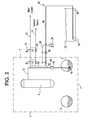
- FIG. 2 is a one-line diagram of a system 40, in accordance with an example embodiment.
- the system 40 may include an alternate reactor pressure vessel (RPV) energy removal line (a steam extraction line) 30 that discharges into a large heat sink (a large body of water), such as the condenser hotwell 32, located outside of the primary containment 7 (the primary containment 7 consisting of portions of a steel primary containment vessel 3, a concrete shell 4 and a steel suppression pool 2, as shown in FIG. 1 ).
- RSV reactor pressure vessel
- the alternate RPV energy removal line 30 may be connected to a quencher pipe 35 in the condenser hotwell 32, and steam discharging through the quencher pipe 35 may exit pipe 35 via a number of quencher holes 34 (that may be used to effectively dissipate the discharged steam throughout the volume of the condenser hotwell 32).
- the quencher pipe 35 may be located along the bottom of the condenser hotwell 32, to maximize the heat exchange between the discharging steam (exiting through the quencher holes 34) and the cool water in the condenser hotwell 32.
- the alternate RPV energy removal line 30 may be a 4 to 6 inch diameter pipe, or another size of pipe that may be large enough to remove the necessary amount of heat from the RPV 1.
- the alternate RPV energy removal line 30 may be connected to either a SRV steam extraction line 31 (connected to the SRV steam line 16, upstream of the SVR valves 18), or a RPV main steam extraction line 33 (connected to the RPV main steam line 12, upstream of the MSIVs 13).
- Two containment isolation valves 36 (one located inside the primary containment boundary 7, and one located outside of primary containment 7) may be located in the alternate RPV energy removal line 30 piping, in order to open or close the alternate RPV energy removal line 30.
- a pressurized gas source 38 (such as pressurized gas bottles, or preferably nitrogen bottles) may provide control gas via a pressure control line 39.
- the gas source 38 may be used by plant personnel to remotely operate the manually operated containment isolation valves 36 without exposing personnel to the RPV 1 or primary containment 7 (in the case of a serious plant accident). Because the containment isolation valves 36 may be opened via the force of the pressurized gas source 38, no external electrical power is necessary to operate the system 40 (which is ideal during a plant accident when plant electrical power may be disrupted).
- FIG. 3 is a flowchart of a method of making a system 40, in accordance with an example embodiment.
- two manually operated containment isolation valves 36 may be inserted into the alternate RPV energy removal line (steam extraction line) 30.
- One containment isolation valve 36 may be located in the primary containment 7, and the other may be located outside of the primary containment 7.
- the alternate RPV energy removal line 30 may discharge excess steam from the RPV 1, as discussed above.
- a pressurized gas source 38 such as pressurized gas bottles 38, may be connected to the containment isolation valves 36.
- the gas source 38 may be located in a position that is remotely located from primary containment 7, to ensure the safe operation of the system 40 without personnel exposure to the primary containment 7 (in the event of a serious plant accident).
- step S54 the alternate RPV energy removal line 30 may be connected to a heat sink, such as the condenser hotwell 32, located outside of primary containment 7.
- a heat sink such as the condenser hotwell 32
- the discharge of excess steam from RPV 1 into the condenser hotwell 32 will allow the steam to be cooled, condensed, and scrubbed of radiation, to safely and effectively reduce excess pressure and heat energy that is located in the RPV 1.
- FIG. 4 is a flowchart of a method of using the system 40 shown in FIG. 2 , in accordance with an example embodiment.
- step S60 may include manually opening the containment isolation valves 36 in the alternate RPV energy removal line (steam extraction line) 30. This may be accomplished using the pressurized gas source 38 that is connected to the containment isolation valves 36.
- step S62 excess steam may be allowed to exit the RPV 1 and primary containment 7 via the alternate RPV energy removal line 30 (due to the opening of the containment isolation valves 36).
- step S64 the extracted steam in the alternate RPV energy removal line 30 may be discharged into the heat sink (such as the condenser hotwell) 32, located outside of primary containment 7.
- the extracted steam may safely and effectively cooled, condensed, and scrubbed of radiation, by being discharged into the heat sink 32, thereby lowering excess pressure that may have otherwise built up in the RPV 1. No external electric power is required to perform the method shown in FIG. 4 .
Landscapes
- Physics & Mathematics (AREA)
- Engineering & Computer Science (AREA)
- Plasma & Fusion (AREA)
- General Engineering & Computer Science (AREA)
- High Energy & Nuclear Physics (AREA)
- Business, Economics & Management (AREA)
- Emergency Management (AREA)
- Structure Of Emergency Protection For Nuclear Reactors (AREA)
Applications Claiming Priority (1)
| Application Number | Priority Date | Filing Date | Title |
|---|---|---|---|
| US13/613,281 US20140072090A1 (en) | 2012-09-13 | 2012-09-13 | Method and system for an alternate rpv energy removal path |
Publications (3)
| Publication Number | Publication Date |
|---|---|
| EP2709112A2 true EP2709112A2 (de) | 2014-03-19 |
| EP2709112A3 EP2709112A3 (de) | 2016-04-13 |
| EP2709112B1 EP2709112B1 (de) | 2017-11-15 |
Family
ID=49303699
Family Applications (1)
| Application Number | Title | Priority Date | Filing Date |
|---|---|---|---|
| EP13184070.4A Not-in-force EP2709112B1 (de) | 2012-09-13 | 2013-09-12 | Verfahren und System für einen alternativen Reaktordruckbehälter-Energieableitungspfad |
Country Status (5)
| Country | Link |
|---|---|
| US (1) | US20140072090A1 (de) |
| EP (1) | EP2709112B1 (de) |
| JP (1) | JP6082677B2 (de) |
| MX (1) | MX349010B (de) |
| TW (1) | TWI598886B (de) |
Families Citing this family (1)
| Publication number | Priority date | Publication date | Assignee | Title |
|---|---|---|---|---|
| US9738440B2 (en) | 2012-12-20 | 2017-08-22 | Ge-Hitachi Nuclear Energy Americas Llc | Entrainment-reducing assembly, system including the assembly, and method of reducing entrainment of gases with the assembly |
Family Cites Families (16)
| Publication number | Priority date | Publication date | Assignee | Title |
|---|---|---|---|---|
| JPS6036987A (ja) * | 1983-08-10 | 1985-02-26 | 株式会社東芝 | 原子炉の主蒸気バイパス装置 |
| DE3643929C1 (en) * | 1986-12-22 | 1988-04-28 | Kernforschungsanlage Juelich | Arrangement for residual heat removal for high-temperature reactors |
| JPS643594A (en) * | 1987-06-26 | 1989-01-09 | Hitachi Ltd | Emergency reactor core cooler |
| JPH0762717B2 (ja) * | 1988-09-21 | 1995-07-05 | 株式会社日立製作所 | 高温高圧容器への注液装置 |
| US5106571A (en) * | 1989-03-20 | 1992-04-21 | Wade Gentry E | Containment heat removal system |
| JPH03183995A (ja) * | 1989-12-14 | 1991-08-09 | Toshiba Corp | 隔離時復水器 |
| JPH05157877A (ja) * | 1991-12-09 | 1993-06-25 | Toshiba Corp | 原子力発電所の冷却設備 |
| JPH05264774A (ja) * | 1992-03-17 | 1993-10-12 | Toshiba Corp | 非常時原子炉冷却装置 |
| US5426681A (en) * | 1994-01-04 | 1995-06-20 | General Electric Company | Boiling water reactor with combined active and passive safety systems |
| JPH11258378A (ja) * | 1998-03-11 | 1999-09-24 | Ishikawajima Harima Heavy Ind Co Ltd | クエンチャサポートのアンカ構造 |
| JP5676905B2 (ja) * | 2010-04-09 | 2015-02-25 | 株式会社東芝 | 逃し安全弁の駆動システム |
| DE102010035510A1 (de) * | 2010-08-25 | 2012-03-01 | Areva Np Gmbh | Verfahren zur Druckentlastung eines Kernkraftwerks, Druckentlastungssystem für ein Kernkraftwerk sowie zugehöriges Kernkraftwerk |
| US8848854B2 (en) * | 2010-09-24 | 2014-09-30 | Westinghouse Electric Company Llc | Alternate feedwater injection system to mitigate the effects of aircraft impact on a nuclear power plant |
| US8638898B2 (en) * | 2011-03-23 | 2014-01-28 | Babcock & Wilcox Mpower, Inc. | Emergency core cooling system for pressurized water reactor |
| TWM425370U (en) * | 2011-10-18 | 2012-03-21 | Iner Aec Executive Yuan | A safety/relief valve discharge system in a BWR |
| JP5911762B2 (ja) * | 2012-06-29 | 2016-04-27 | 株式会社東芝 | 原子力プラントおよび静的格納容器冷却系 |
-
2012
- 2012-09-13 US US13/613,281 patent/US20140072090A1/en not_active Abandoned
-
2013
- 2013-08-30 TW TW102131422A patent/TWI598886B/zh active
- 2013-09-10 JP JP2013186877A patent/JP6082677B2/ja not_active Expired - Fee Related
- 2013-09-12 EP EP13184070.4A patent/EP2709112B1/de not_active Not-in-force
- 2013-09-13 MX MX2013010564A patent/MX349010B/es active IP Right Grant
Non-Patent Citations (1)
| Title |
|---|
| None |
Also Published As
| Publication number | Publication date |
|---|---|
| JP6082677B2 (ja) | 2017-02-15 |
| EP2709112A3 (de) | 2016-04-13 |
| US20140072090A1 (en) | 2014-03-13 |
| MX2013010564A (es) | 2014-03-21 |
| TW201421490A (zh) | 2014-06-01 |
| TWI598886B (zh) | 2017-09-11 |
| EP2709112B1 (de) | 2017-11-15 |
| MX349010B (es) | 2017-07-06 |
| JP2014055951A (ja) | 2014-03-27 |
Similar Documents
| Publication | Publication Date | Title |
|---|---|---|
| US9697914B2 (en) | Nuclear power plant and passive containment cooling system | |
| US11646123B2 (en) | Three-way valve operational to both transfer steam to a decontamination water tank under one accident situation and discharge the steam to atmosphere under a different accident situation | |
| JP2009150846A (ja) | 原子炉格納容器およびそれを用いた原子力プラント | |
| KR102577167B1 (ko) | 상업적 전기 생산을 위한 매우 단순화된 비등수 원자로들 | |
| KR101250479B1 (ko) | 안전보호용기를 구비한 피동형 비상노심냉각설비 및 이를 이용한 열 전달량 증가 방법 | |
| EP3667678B1 (de) | Druckentlastungsventil | |
| JP2020525789A (ja) | 非常に単純化された沸騰水反応器のための非常用復水器 | |
| WO2015142407A2 (en) | Passively initiated depressurization valve for light water reactors | |
| EP2709112B1 (de) | Verfahren und System für einen alternativen Reaktordruckbehälter-Energieableitungspfad | |
| WO2015156853A3 (en) | Reactor containment pressure suppression | |
| EP2608214B1 (de) | Verfahren und Vorrichtung für ein alternatives, entferntes System für Kühlbeckenkühlung für abgebrannten Brennstoff für Leichtwasserreaktoren | |
| EP2706533B1 (de) | Verfahren und System zur externen alternativen Kondensationsbeckenkühlung für Siedewasserreaktoren | |
| EP2657941B1 (de) | Wärmeabfuhrsystem und verfahren für einen kernreaktor | |
| JP3173276U (ja) | 沸騰水型原子炉の逃がし安全弁放出ラインヘッダー | |
| EP3669378B1 (de) | Vereinfachtes kernreaktorsystem und verfahren zur herstellung eines solchen systems | |
| JP2012230033A (ja) | 原子炉格納容器の冷却装置 | |
| US20140072089A1 (en) | Method and system for an alternative bwr containment heat removal system | |
| EP1122743A1 (de) | Vorrichtungen und Verfahren zum Aufrechterhalten der Integrität eines Kernreaktor-Sicherheitsbehälters | |
| Alblouwy et al. | Evaluation of Multiple Steam Generator Tubes Rupture for SMART | |
| Kim et al. | A Comparative Study between a SGTR and a SG Module Pipe Break Accident of the Integral Type Reactor | |
| Park et al. | Evaluation of multiple steam generator tube rupture events for KNGR |
Legal Events
| Date | Code | Title | Description |
|---|---|---|---|
| PUAI | Public reference made under article 153(3) epc to a published international application that has entered the european phase |
Free format text: ORIGINAL CODE: 0009012 |
|
| AK | Designated contracting states |
Kind code of ref document: A2 Designated state(s): AL AT BE BG CH CY CZ DE DK EE ES FI FR GB GR HR HU IE IS IT LI LT LU LV MC MK MT NL NO PL PT RO RS SE SI SK SM TR |
|
| AX | Request for extension of the european patent |
Extension state: BA ME |
|
| PUAL | Search report despatched |
Free format text: ORIGINAL CODE: 0009013 |
|
| AK | Designated contracting states |
Kind code of ref document: A3 Designated state(s): AL AT BE BG CH CY CZ DE DK EE ES FI FR GB GR HR HU IE IS IT LI LT LU LV MC MK MT NL NO PL PT RO RS SE SI SK SM TR |
|
| AX | Request for extension of the european patent |
Extension state: BA ME |
|
| RIC1 | Information provided on ipc code assigned before grant |
Ipc: G21C 15/18 20060101ALI20160310BHEP Ipc: G21D 3/04 20060101ALI20160310BHEP Ipc: G21C 9/012 20060101AFI20160310BHEP Ipc: G21C 15/12 20060101ALN20160310BHEP Ipc: G21D 1/02 20060101ALI20160310BHEP Ipc: G21C 9/004 20060101ALN20160310BHEP |
|
| 17P | Request for examination filed |
Effective date: 20161013 |
|
| RBV | Designated contracting states (corrected) |
Designated state(s): AL AT BE BG CH CY CZ DE DK EE ES FI FR GB GR HR HU IE IS IT LI LT LU LV MC MK MT NL NO PL PT RO RS SE SI SK SM TR |
|
| REG | Reference to a national code |
Ref country code: DE Ref legal event code: R079 Ref document number: 602013029392 Country of ref document: DE Free format text: PREVIOUS MAIN CLASS: G21C0009004000 Ipc: G21C0009012000 |
|
| GRAP | Despatch of communication of intention to grant a patent |
Free format text: ORIGINAL CODE: EPIDOSNIGR1 |
|
| RIC1 | Information provided on ipc code assigned before grant |
Ipc: G21C 9/004 20060101ALI20170607BHEP Ipc: G21D 3/04 20060101ALI20170607BHEP Ipc: G21C 15/18 20060101ALI20170607BHEP Ipc: G21C 15/12 20060101ALN20170607BHEP Ipc: G21D 1/02 20060101ALI20170607BHEP Ipc: G21C 9/012 20060101AFI20170607BHEP |
|
| INTG | Intention to grant announced |
Effective date: 20170628 |
|
| GRAS | Grant fee paid |
Free format text: ORIGINAL CODE: EPIDOSNIGR3 |
|
| GRAA | (expected) grant |
Free format text: ORIGINAL CODE: 0009210 |
|
| AK | Designated contracting states |
Kind code of ref document: B1 Designated state(s): AL AT BE BG CH CY CZ DE DK EE ES FI FR GB GR HR HU IE IS IT LI LT LU LV MC MK MT NL NO PL PT RO RS SE SI SK SM TR |
|
| REG | Reference to a national code |
Ref country code: CH Ref legal event code: EP Ref country code: GB Ref legal event code: FG4D Ref country code: AT Ref legal event code: REF Ref document number: 947002 Country of ref document: AT Kind code of ref document: T Effective date: 20171115 |
|
| REG | Reference to a national code |
Ref country code: IE Ref legal event code: FG4D |
|
| REG | Reference to a national code |
Ref country code: DE Ref legal event code: R096 Ref document number: 602013029392 Country of ref document: DE |
|
| REG | Reference to a national code |
Ref country code: NL Ref legal event code: MP Effective date: 20171115 |
|
| REG | Reference to a national code |
Ref country code: LT Ref legal event code: MG4D |
|
| REG | Reference to a national code |
Ref country code: AT Ref legal event code: MK05 Ref document number: 947002 Country of ref document: AT Kind code of ref document: T Effective date: 20171115 |
|
| PG25 | Lapsed in a contracting state [announced via postgrant information from national office to epo] |
Ref country code: ES Free format text: LAPSE BECAUSE OF FAILURE TO SUBMIT A TRANSLATION OF THE DESCRIPTION OR TO PAY THE FEE WITHIN THE PRESCRIBED TIME-LIMIT Effective date: 20171115 Ref country code: SE Free format text: LAPSE BECAUSE OF FAILURE TO SUBMIT A TRANSLATION OF THE DESCRIPTION OR TO PAY THE FEE WITHIN THE PRESCRIBED TIME-LIMIT Effective date: 20171115 Ref country code: NL Free format text: LAPSE BECAUSE OF FAILURE TO SUBMIT A TRANSLATION OF THE DESCRIPTION OR TO PAY THE FEE WITHIN THE PRESCRIBED TIME-LIMIT Effective date: 20171115 Ref country code: LT Free format text: LAPSE BECAUSE OF FAILURE TO SUBMIT A TRANSLATION OF THE DESCRIPTION OR TO PAY THE FEE WITHIN THE PRESCRIBED TIME-LIMIT Effective date: 20171115 Ref country code: NO Free format text: LAPSE BECAUSE OF FAILURE TO SUBMIT A TRANSLATION OF THE DESCRIPTION OR TO PAY THE FEE WITHIN THE PRESCRIBED TIME-LIMIT Effective date: 20180215 Ref country code: FI Free format text: LAPSE BECAUSE OF FAILURE TO SUBMIT A TRANSLATION OF THE DESCRIPTION OR TO PAY THE FEE WITHIN THE PRESCRIBED TIME-LIMIT Effective date: 20171115 |
|
| PG25 | Lapsed in a contracting state [announced via postgrant information from national office to epo] |
Ref country code: AT Free format text: LAPSE BECAUSE OF FAILURE TO SUBMIT A TRANSLATION OF THE DESCRIPTION OR TO PAY THE FEE WITHIN THE PRESCRIBED TIME-LIMIT Effective date: 20171115 Ref country code: GR Free format text: LAPSE BECAUSE OF FAILURE TO SUBMIT A TRANSLATION OF THE DESCRIPTION OR TO PAY THE FEE WITHIN THE PRESCRIBED TIME-LIMIT Effective date: 20180216 Ref country code: HR Free format text: LAPSE BECAUSE OF FAILURE TO SUBMIT A TRANSLATION OF THE DESCRIPTION OR TO PAY THE FEE WITHIN THE PRESCRIBED TIME-LIMIT Effective date: 20171115 Ref country code: BG Free format text: LAPSE BECAUSE OF FAILURE TO SUBMIT A TRANSLATION OF THE DESCRIPTION OR TO PAY THE FEE WITHIN THE PRESCRIBED TIME-LIMIT Effective date: 20180215 Ref country code: LV Free format text: LAPSE BECAUSE OF FAILURE TO SUBMIT A TRANSLATION OF THE DESCRIPTION OR TO PAY THE FEE WITHIN THE PRESCRIBED TIME-LIMIT Effective date: 20171115 Ref country code: RS Free format text: LAPSE BECAUSE OF FAILURE TO SUBMIT A TRANSLATION OF THE DESCRIPTION OR TO PAY THE FEE WITHIN THE PRESCRIBED TIME-LIMIT Effective date: 20171115 |
|
| PG25 | Lapsed in a contracting state [announced via postgrant information from national office to epo] |
Ref country code: DK Free format text: LAPSE BECAUSE OF FAILURE TO SUBMIT A TRANSLATION OF THE DESCRIPTION OR TO PAY THE FEE WITHIN THE PRESCRIBED TIME-LIMIT Effective date: 20171115 Ref country code: CY Free format text: LAPSE BECAUSE OF FAILURE TO SUBMIT A TRANSLATION OF THE DESCRIPTION OR TO PAY THE FEE WITHIN THE PRESCRIBED TIME-LIMIT Effective date: 20171115 Ref country code: EE Free format text: LAPSE BECAUSE OF FAILURE TO SUBMIT A TRANSLATION OF THE DESCRIPTION OR TO PAY THE FEE WITHIN THE PRESCRIBED TIME-LIMIT Effective date: 20171115 Ref country code: SK Free format text: LAPSE BECAUSE OF FAILURE TO SUBMIT A TRANSLATION OF THE DESCRIPTION OR TO PAY THE FEE WITHIN THE PRESCRIBED TIME-LIMIT Effective date: 20171115 Ref country code: CZ Free format text: LAPSE BECAUSE OF FAILURE TO SUBMIT A TRANSLATION OF THE DESCRIPTION OR TO PAY THE FEE WITHIN THE PRESCRIBED TIME-LIMIT Effective date: 20171115 |
|
| REG | Reference to a national code |
Ref country code: DE Ref legal event code: R097 Ref document number: 602013029392 Country of ref document: DE |
|
| PG25 | Lapsed in a contracting state [announced via postgrant information from national office to epo] |
Ref country code: IT Free format text: LAPSE BECAUSE OF FAILURE TO SUBMIT A TRANSLATION OF THE DESCRIPTION OR TO PAY THE FEE WITHIN THE PRESCRIBED TIME-LIMIT Effective date: 20171115 Ref country code: SM Free format text: LAPSE BECAUSE OF FAILURE TO SUBMIT A TRANSLATION OF THE DESCRIPTION OR TO PAY THE FEE WITHIN THE PRESCRIBED TIME-LIMIT Effective date: 20171115 Ref country code: RO Free format text: LAPSE BECAUSE OF FAILURE TO SUBMIT A TRANSLATION OF THE DESCRIPTION OR TO PAY THE FEE WITHIN THE PRESCRIBED TIME-LIMIT Effective date: 20171115 Ref country code: PL Free format text: LAPSE BECAUSE OF FAILURE TO SUBMIT A TRANSLATION OF THE DESCRIPTION OR TO PAY THE FEE WITHIN THE PRESCRIBED TIME-LIMIT Effective date: 20171115 |
|
| PLBE | No opposition filed within time limit |
Free format text: ORIGINAL CODE: 0009261 |
|
| STAA | Information on the status of an ep patent application or granted ep patent |
Free format text: STATUS: NO OPPOSITION FILED WITHIN TIME LIMIT |
|
| 26N | No opposition filed |
Effective date: 20180817 |
|
| PG25 | Lapsed in a contracting state [announced via postgrant information from national office to epo] |
Ref country code: SI Free format text: LAPSE BECAUSE OF FAILURE TO SUBMIT A TRANSLATION OF THE DESCRIPTION OR TO PAY THE FEE WITHIN THE PRESCRIBED TIME-LIMIT Effective date: 20171115 |
|
| REG | Reference to a national code |
Ref country code: DE Ref legal event code: R119 Ref document number: 602013029392 Country of ref document: DE |
|
| PG25 | Lapsed in a contracting state [announced via postgrant information from national office to epo] |
Ref country code: MC Free format text: LAPSE BECAUSE OF FAILURE TO SUBMIT A TRANSLATION OF THE DESCRIPTION OR TO PAY THE FEE WITHIN THE PRESCRIBED TIME-LIMIT Effective date: 20171115 |
|
| REG | Reference to a national code |
Ref country code: CH Ref legal event code: PL |
|
| GBPC | Gb: european patent ceased through non-payment of renewal fee |
Effective date: 20180912 |
|
| REG | Reference to a national code |
Ref country code: BE Ref legal event code: MM Effective date: 20180930 |
|
| REG | Reference to a national code |
Ref country code: IE Ref legal event code: MM4A |
|
| PG25 | Lapsed in a contracting state [announced via postgrant information from national office to epo] |
Ref country code: LU Free format text: LAPSE BECAUSE OF NON-PAYMENT OF DUE FEES Effective date: 20180912 |
|
| PG25 | Lapsed in a contracting state [announced via postgrant information from national office to epo] |
Ref country code: DE Free format text: LAPSE BECAUSE OF NON-PAYMENT OF DUE FEES Effective date: 20190402 Ref country code: IE Free format text: LAPSE BECAUSE OF NON-PAYMENT OF DUE FEES Effective date: 20180912 |
|
| PG25 | Lapsed in a contracting state [announced via postgrant information from national office to epo] |
Ref country code: LI Free format text: LAPSE BECAUSE OF NON-PAYMENT OF DUE FEES Effective date: 20180930 Ref country code: BE Free format text: LAPSE BECAUSE OF NON-PAYMENT OF DUE FEES Effective date: 20180930 Ref country code: FR Free format text: LAPSE BECAUSE OF NON-PAYMENT OF DUE FEES Effective date: 20180930 Ref country code: CH Free format text: LAPSE BECAUSE OF NON-PAYMENT OF DUE FEES Effective date: 20180930 |
|
| PG25 | Lapsed in a contracting state [announced via postgrant information from national office to epo] |
Ref country code: GB Free format text: LAPSE BECAUSE OF NON-PAYMENT OF DUE FEES Effective date: 20180912 |
|
| PG25 | Lapsed in a contracting state [announced via postgrant information from national office to epo] |
Ref country code: MT Free format text: LAPSE BECAUSE OF NON-PAYMENT OF DUE FEES Effective date: 20180912 |
|
| PG25 | Lapsed in a contracting state [announced via postgrant information from national office to epo] |
Ref country code: TR Free format text: LAPSE BECAUSE OF FAILURE TO SUBMIT A TRANSLATION OF THE DESCRIPTION OR TO PAY THE FEE WITHIN THE PRESCRIBED TIME-LIMIT Effective date: 20171115 |
|
| PG25 | Lapsed in a contracting state [announced via postgrant information from national office to epo] |
Ref country code: HU Free format text: LAPSE BECAUSE OF FAILURE TO SUBMIT A TRANSLATION OF THE DESCRIPTION OR TO PAY THE FEE WITHIN THE PRESCRIBED TIME-LIMIT; INVALID AB INITIO Effective date: 20130912 Ref country code: PT Free format text: LAPSE BECAUSE OF FAILURE TO SUBMIT A TRANSLATION OF THE DESCRIPTION OR TO PAY THE FEE WITHIN THE PRESCRIBED TIME-LIMIT Effective date: 20171115 |
|
| PG25 | Lapsed in a contracting state [announced via postgrant information from national office to epo] |
Ref country code: MK Free format text: LAPSE BECAUSE OF NON-PAYMENT OF DUE FEES Effective date: 20171115 |
|
| PG25 | Lapsed in a contracting state [announced via postgrant information from national office to epo] |
Ref country code: AL Free format text: LAPSE BECAUSE OF FAILURE TO SUBMIT A TRANSLATION OF THE DESCRIPTION OR TO PAY THE FEE WITHIN THE PRESCRIBED TIME-LIMIT Effective date: 20171115 Ref country code: IS Free format text: LAPSE BECAUSE OF FAILURE TO SUBMIT A TRANSLATION OF THE DESCRIPTION OR TO PAY THE FEE WITHIN THE PRESCRIBED TIME-LIMIT Effective date: 20180315 |