EP2708768A2 - Antriebseinheit für ein Kraftfahrzeug mit einer elektrischen Maschine und einer Kupplung - Google Patents
Antriebseinheit für ein Kraftfahrzeug mit einer elektrischen Maschine und einer Kupplung Download PDFInfo
- Publication number
- EP2708768A2 EP2708768A2 EP13180797.6A EP13180797A EP2708768A2 EP 2708768 A2 EP2708768 A2 EP 2708768A2 EP 13180797 A EP13180797 A EP 13180797A EP 2708768 A2 EP2708768 A2 EP 2708768A2
- Authority
- EP
- European Patent Office
- Prior art keywords
- drive unit
- disengagement
- unit according
- actuator
- actuating device
- Prior art date
- Legal status (The legal status is an assumption and is not a legal conclusion. Google has not performed a legal analysis and makes no representation as to the accuracy of the status listed.)
- Granted
Links
Images


Classifications
-
- H—ELECTRICITY
- H02—GENERATION; CONVERSION OR DISTRIBUTION OF ELECTRIC POWER
- H02K—DYNAMO-ELECTRIC MACHINES
- H02K7/00—Arrangements for handling mechanical energy structurally associated with dynamo-electric machines, e.g. structural association with mechanical driving motors or auxiliary dynamo-electric machines
- H02K7/10—Structural association with clutches, brakes, gears, pulleys or mechanical starters
- H02K7/108—Structural association with clutches, brakes, gears, pulleys or mechanical starters with friction clutches
-
- B—PERFORMING OPERATIONS; TRANSPORTING
- B60—VEHICLES IN GENERAL
- B60K—ARRANGEMENT OR MOUNTING OF PROPULSION UNITS OR OF TRANSMISSIONS IN VEHICLES; ARRANGEMENT OR MOUNTING OF PLURAL DIVERSE PRIME-MOVERS IN VEHICLES; AUXILIARY DRIVES FOR VEHICLES; INSTRUMENTATION OR DASHBOARDS FOR VEHICLES; ARRANGEMENTS IN CONNECTION WITH COOLING, AIR INTAKE, GAS EXHAUST OR FUEL SUPPLY OF PROPULSION UNITS IN VEHICLES
- B60K6/00—Arrangement or mounting of plural diverse prime-movers for mutual or common propulsion, e.g. hybrid propulsion systems comprising electric motors and internal combustion engines
- B60K6/20—Arrangement or mounting of plural diverse prime-movers for mutual or common propulsion, e.g. hybrid propulsion systems comprising electric motors and internal combustion engines the prime-movers consisting of electric motors and internal combustion engines, e.g. HEVs
- B60K6/22—Arrangement or mounting of plural diverse prime-movers for mutual or common propulsion, e.g. hybrid propulsion systems comprising electric motors and internal combustion engines the prime-movers consisting of electric motors and internal combustion engines, e.g. HEVs characterised by apparatus, components or means specially adapted for HEVs
- B60K6/38—Arrangement or mounting of plural diverse prime-movers for mutual or common propulsion, e.g. hybrid propulsion systems comprising electric motors and internal combustion engines the prime-movers consisting of electric motors and internal combustion engines, e.g. HEVs characterised by apparatus, components or means specially adapted for HEVs characterised by the driveline clutches
- B60K6/387—Actuated clutches, i.e. clutches engaged or disengaged by electric, hydraulic or mechanical actuating means
-
- F—MECHANICAL ENGINEERING; LIGHTING; HEATING; WEAPONS; BLASTING
- F16—ENGINEERING ELEMENTS AND UNITS; GENERAL MEASURES FOR PRODUCING AND MAINTAINING EFFECTIVE FUNCTIONING OF MACHINES OR INSTALLATIONS; THERMAL INSULATION IN GENERAL
- F16D—COUPLINGS FOR TRANSMITTING ROTATION; CLUTCHES; BRAKES
- F16D23/00—Details of mechanically-actuated clutches not specific for one distinct type
- F16D23/12—Mechanical clutch-actuating mechanisms arranged outside the clutch as such
- F16D23/14—Clutch-actuating sleeves or bearings; Actuating members directly connected to clutch-actuating sleeves or bearings
-
- F—MECHANICAL ENGINEERING; LIGHTING; HEATING; WEAPONS; BLASTING
- F16—ENGINEERING ELEMENTS AND UNITS; GENERAL MEASURES FOR PRODUCING AND MAINTAINING EFFECTIVE FUNCTIONING OF MACHINES OR INSTALLATIONS; THERMAL INSULATION IN GENERAL
- F16D—COUPLINGS FOR TRANSMITTING ROTATION; CLUTCHES; BRAKES
- F16D28/00—Electrically-actuated clutches
-
- H—ELECTRICITY
- H02—GENERATION; CONVERSION OR DISTRIBUTION OF ELECTRIC POWER
- H02K—DYNAMO-ELECTRIC MACHINES
- H02K7/00—Arrangements for handling mechanical energy structurally associated with dynamo-electric machines, e.g. structural association with mechanical driving motors or auxiliary dynamo-electric machines
- H02K7/10—Structural association with clutches, brakes, gears, pulleys or mechanical starters
- H02K7/116—Structural association with clutches, brakes, gears, pulleys or mechanical starters with gears
-
- B—PERFORMING OPERATIONS; TRANSPORTING
- B60—VEHICLES IN GENERAL
- B60K—ARRANGEMENT OR MOUNTING OF PROPULSION UNITS OR OF TRANSMISSIONS IN VEHICLES; ARRANGEMENT OR MOUNTING OF PLURAL DIVERSE PRIME-MOVERS IN VEHICLES; AUXILIARY DRIVES FOR VEHICLES; INSTRUMENTATION OR DASHBOARDS FOR VEHICLES; ARRANGEMENTS IN CONNECTION WITH COOLING, AIR INTAKE, GAS EXHAUST OR FUEL SUPPLY OF PROPULSION UNITS IN VEHICLES
- B60K6/00—Arrangement or mounting of plural diverse prime-movers for mutual or common propulsion, e.g. hybrid propulsion systems comprising electric motors and internal combustion engines
- B60K6/20—Arrangement or mounting of plural diverse prime-movers for mutual or common propulsion, e.g. hybrid propulsion systems comprising electric motors and internal combustion engines the prime-movers consisting of electric motors and internal combustion engines, e.g. HEVs
- B60K6/42—Arrangement or mounting of plural diverse prime-movers for mutual or common propulsion, e.g. hybrid propulsion systems comprising electric motors and internal combustion engines the prime-movers consisting of electric motors and internal combustion engines, e.g. HEVs characterised by the architecture of the hybrid electric vehicle
- B60K6/48—Parallel type
- B60K2006/4825—Electric machine connected or connectable to gearbox input shaft
-
- F—MECHANICAL ENGINEERING; LIGHTING; HEATING; WEAPONS; BLASTING
- F16—ENGINEERING ELEMENTS AND UNITS; GENERAL MEASURES FOR PRODUCING AND MAINTAINING EFFECTIVE FUNCTIONING OF MACHINES OR INSTALLATIONS; THERMAL INSULATION IN GENERAL
- F16D—COUPLINGS FOR TRANSMITTING ROTATION; CLUTCHES; BRAKES
- F16D23/00—Details of mechanically-actuated clutches not specific for one distinct type
- F16D23/12—Mechanical clutch-actuating mechanisms arranged outside the clutch as such
- F16D2023/123—Clutch actuation by cams, ramps or ball-screw mechanisms
-
- Y—GENERAL TAGGING OF NEW TECHNOLOGICAL DEVELOPMENTS; GENERAL TAGGING OF CROSS-SECTIONAL TECHNOLOGIES SPANNING OVER SEVERAL SECTIONS OF THE IPC; TECHNICAL SUBJECTS COVERED BY FORMER USPC CROSS-REFERENCE ART COLLECTIONS [XRACs] AND DIGESTS
- Y02—TECHNOLOGIES OR APPLICATIONS FOR MITIGATION OR ADAPTATION AGAINST CLIMATE CHANGE
- Y02T—CLIMATE CHANGE MITIGATION TECHNOLOGIES RELATED TO TRANSPORTATION
- Y02T10/00—Road transport of goods or passengers
- Y02T10/60—Other road transportation technologies with climate change mitigation effect
- Y02T10/62—Hybrid vehicles
Definitions
- the invention relates to a drive unit for a motor vehicle according to the preamble of the independent claim.
- Such a generic drive unit is for example with the EP 2 148 107 B1 has become known and can be used alone or in conjunction with an internal combustion engine in the drive train of a motor vehicle.
- the actuator is preferably provided there as a hydraulic or pneumatic Gottitzer.
- a disadvantage of this unit is a resulting from the laying of the pressure transmission lines of the clutch actuator resulting relatively high installation costs and a correspondingly large space requirement felt.
- the transmission ratios of the actuator can vary by a required long pressure line guide and by the temperature dependence of the fluid used and thus adversely affect a desired amount of disengagement of the clutch.
- the EP 0 716 242 B1 discloses an actuator not associated with the aforementioned genus with an electric motor drive for a means of a diaphragm spring actuated vehicle friction clutch.
- the electromotive drive in this case has an electric actuator motor with a transversely directed to a release axis of the clutch actuator shaft, which engages by means of a worm in a, a worm wheel representing externally toothed housing segment of a release bearing of the clutch.
- the release bearing housing is rotatably mounted on a stationary support by means of a coarse thread.
- the bearing housing leads through the worm and worm-wheel combination simply squat rotational movement, which is simultaneously implemented as a result of the steep thread in an axial movement.
- an end bearing arranged on the housing release bearing is moved toward a Kupplungsaus Wegorgan, causing disengagement of the clutch.
- the coarse thread for adjusting the Aus Weglagergeophuses requires a relatively high actuating torque, including the radial distance of the worm drive from the rotational or Ausgurachse must be chosen to be relatively large.
- the actuator shaft of the externally fixed to an approximately cylindrical gear housing electric motor in terms of their bending and torsional stiffness sufficiently large.
- the axial width of the worm wheel segment is to be selected so that an engagement with the worm over the entire travel is ensured in an actuating operation. Since the worm wheel segment is displaced axially in addition to a rotational movement against the action of the diaphragm spring, very high frictional forces occur on the worm gear, which unfavorably influence the efficiency of the actuating device.
- the invention has the object to improve a generic drive unit, in particular with regard to the actuating device of the clutch.
- the invention provides, in a drive unit of the aforementioned type, the actuating device with an electric actuator motor and with an actuator shaft form, which is in operative connection with a disengagement.
- the disengagement arrangement converts a rotational movement of the actuator shaft into a translation movement acting on the disengagement member of the clutch.
- the disengagement assembly comprises a rotatable and axially to the disengagement member fixed input member and an axially displaceable to this output member, which is in operative connection with the disengagement member.
- the cooperating with the actuator shaft input element of the disengagement assembly can perform only a pivoting or pivoting movement about a Ausgurachse, whereby the frictional forces acting at this position can be reduced and the efficiency of the actuator can be increased overall.
- Compared to an actuator known from the prior art can be dispensed with the laborious installation of pressure lines and the required hydraulic or pneumatic coupling points. The laying of electrical cables to control an actuator motor designed comparatively easy.
- a reduction gear between the actuator shaft and the input element of the disengagement assembly, which may be carried out in particular with a first and with a second gear stage
- a transmission ratio i defined by the output rotational speed of the actuator motor and the input rotational speed of the disengagement arrangement is preferably greater than 50, more preferably greater than 100, in particular greater than 120.
- the at least two-step reduction which is advantageously arranged in the region of the disengagement arrangement, allows the actuator drive shaft to be comparatively be executed briefly. Because of the relatively lower torque to be transmitted by the actuator shaft, it still needs to have only a relatively small diameter. In other words, the claimed by the actuator shaft axial space requirement is comparatively low.
- the ratio of an axial travel of the output element of the disengagement assembly to a rotational angle of the actuator shaft may be basically linear. However, it may alternatively prove to be particularly advantageous if this Ratio has a non-linear course.
- Such variable over the travel of the disengaging variable translation of the actuator can be particularly favorable in connection with a variable ratio of the disengagement, for example, a diaphragm spring. This may be the case if the travel impressed on the input region of the diaphragm spring by the disengagement device behaves in a nonlinear relationship to an axial travel generated at the output region of the diaphragm spring.
- a nonlinear transmission characteristic explained at the outset may also be favorable for an arealwise increase in the disengagement force acting on the disengagement member even if the disengagement member has a linear transmission characteristic.
- the input element and the output element are preferably designed with corresponding ball ramps or tracks and between these running balls and arranged axially relative to one another.
- the ball tracks or ramps are arranged frontally on the input and output element, resulting in a space-saving and only small radial expansion of the disengagement order result.
- a first gear stage of the reduction gear comprises a worm gear, wherein the actuator shaft carries a worm or can be coupled with a worm, which cooperates with a worm wheel.
- This worm wheel may be designed separately or in a unit with a spur gear, which serves as part of a second gear stage of the reduction gear and which is engaged with another, preferably with the input element of the disengagement arrangement or arranged on this further spur gear for transmitting and reducing an actuator rotary motion ,
- the actuating device is designed to be self-locking, so that the disengaging member of the connected clutch remains in the axial position last approached even when the actuator motor is de-energized.
- the self-locking can be particularly preferred, but not exclusively realized by means of a worm gear, ie between a worm and a worm wheel become.
- the actuator may also be self-resetting with particular safety advantage.
- a particularly space-saving design of the drive unit can be achieved by the actuator shaft is directed transversely to the axis of rotation A of the drive unit and axially adjacent to the stator and by the actuator motor is disposed radially outside of the drive unit serving as the electric machine.
- the actuator motor and the drive unit space-saving overlap each other axially.
- the actuator motor can preferably be fixed to a housing surrounding the drive unit, where it is particularly easy to access for maintenance or replacement.
- the actuating device can be fixed at least indirectly on the stator of the electric machine, in particular with the actuator shaft, optionally with the reduction gear and with the disengagement arrangement, and be supported against an acting clutch actuation force.
- a stator or a fixedly connected to the stator further element, such as a connected to the stator housing or the like is suitable.
- the disengagement arrangement has a device for compensating a pad wear of the friction disc, which causes the permanent contact contact of the diaphragm spring on the release bearing regardless of a degree of wear of the friction disc.
- the drive unit 10 for a hybrid vehicle shown in the figures initially comprises a drive unit 14 designed as an electric machine 12 with a stator 16 and a rotor 18 rotatably mounted about a rotation axis A coaxial therewith.
- the electric machine 12 is in the present case designed as an external rotor machine and can however be installed in Depending on the available installation space conditions, in principle also be designed as an internal rotor machine.
- the drive unit 10 further includes a clutch 20 formed here in assembly with the electric machine 12, in particular a switchable friction clutch for producing a rotary driving connection of the rotor 18 with at least one further drive element of the vehicle drive train.
- the rotor 18 comprises a magnetically active portion 18a with a laminated core and permanent magnets arranged thereon, and further comprises a cup-shaped rotor carrier 18b here.
- the rotor carrier 18b contributes to the formation of the coupling 20 with this rotatable, annular pressure plate assembly 22 which is displaceable in the direction of a non-rotatably connected to the rotor 18 pressure plate 24.
- the pressure plate assembly 22 has for this purpose a plurality of circumferentially distributed axial extensions 22a, which extend through axial openings of the rotor support 18b.
- the diaphragm spring 26 is pivotably mounted on an axial cutting extension 30 of the rotor carrier 18b and rests with a radially outer ring portion 26a on the projections 22a and with radially inwardly extending spring tongues 26b a disengagement assembly 32 at.
- the disengagement assembly 32 is a component of an actuator 34 for actuating the friction clutch 20, by means of which the inner portions of the diaphragm spring tongues 26b are axially displaceable and over which the diaphragm spring 26 can act on the pressure plate assembly 22 axially by means of the above-described lever assembly.
- Axially between the pressure plate assembly 22 and the pressure plate 24 is a likewise axially displaceable friction plate 35 is provided, which can accommodate a torque of the electric machine 12 and / or a einleitbares on the rotor 18 torque when the clutch 20 is closed.
- the pressure plate 24 connected to the rotor 18 or executed there has a rotary drive arrangement 38.
- this involves a hub 38a, which is connected to the pressure plate 24 and which carries a form-fitting profile 38b in the manner of a toothing, in particular a spur toothing.
- the hub 38 can thus be easily operatively connected to other elements of the vehicle drive train, for example a subsequent transmission.
- the friction disc or clutch disc 35 is connected to a drive shaft 40, which is made centrally within the electric machine 12, in a rotary driving connection, which can forward a torque, for example, to a crankshaft of an internal combustion engine of the motor vehicle.
- a torque output by an internal combustion engine via the drive shaft 40 and the friction disc 35 act on the rotor 18 and are delivered simultaneously via the connection arrangement to other, not shown here Antriebsstrangimplantation.
- the rotor 18 is in turn rotatably mounted concentrically to the stator 16 by means of a fixed to a stator 16a bearing assembly 44 and also fixed axially to the stator 16.
- This bearing assembly 44 is formed in the embodiment as a rolling bearing 46, in particular as a double-row ball bearing, which is received within a sleeve-shaped and axially, centrally within the stator 16 on the stator support 16a extending bearing support 48.
- annular receiving space 17 Radial between the stator support 16a and the bearing support 48, an annular receiving space 17 is formed, which, as described in more detail below, at least part of the actuating device 34 receives for actuating the friction clutch 20.
- the actuating device 34 comprises an electric actuator motor 36 with an actuator shaft 36a directed transversely to the axis of rotation A of the drive unit 12, 14 and the aforementioned disengagement arrangement 32.
- the actuator motor 36 is arranged radially outside the electric machine 12.
- the actuator shaft 36a extends axially adjacent to the stator 16 and transversely, in particular substantially perpendicular to the axis of rotation A of the electric machine, which in this case coincides with a release axis B of the disengagement assembly 32.
- the illustrated drive unit 10 is provided for arrangement in a housing, not shown in the drawing, for example, in a transmission housing or in a separate intermediate housing of the vehicle drive train.
- the actuator motor 36 can be fixed by means of a plurality of fastening tabs 36b on the outside of the housing.
- the disengagement assembly 32 is operatively connected to the actuator shaft 36a and is configured to rotationally move the actuator shaft 36a into a the release member 28 of the clutch 20 to translate effective translational movement.
- the disengagement assembly 32 includes a rotatable and axially to the disengaging member 28 fixed input member 32a and an axially displaceable to this output member 32b, which for rotational decoupling via a release bearing 36c with the disengagement member 28, i. the diaphragm spring 26 is in operative connection.
- the disengagement assembly 32 is designed as a ball ramp drive, run between the input member 32a and the output member 32b in ramps guided balls.
- the disengagement assembly 32 further includes means 60 for compensating for pad wear of the friction washer 35 which, regardless of a degree of wear of the friction washer 35, causes permanent engagement of the diaphragm spring 26 with the disengagement bearing 36c.
- the output element 32b comprises a bearing support 32d axially displaceable by means of guide pins 32e to a base body 32c, which receives the release bearing 36c with one of its bearing rings 36f, here the outer bearing ring 36f.
- the other, with the clutch 20 encircling bearing ring 36g abuts on a bearing plate 36h at the free ends of the spring tongues 26b.
- the axial movement space of the bearing support 32d is limited on the one hand in the direction of the coupling 20 by a stop on the guide pin 32e and on the other hand in the opposite direction by a stop on the base body 32c.
- Axially between the bearing support 32d and the main body 32c is an elastic element 32i, clamped here a plate spring, which loads the bearing support 32d in the direction of the diaphragm spring 26 and brings the release bearing 36c by means of the bearing plate 36h to the diaphragm spring tongues 26b to the plant.
- the bearing support 32d is thus displaced in the unworn new state of the friction disc 35 relative to the main body 32c of the output element 32b by a distance, which is preferably at least equal to or greater than a release-wear path x explained below.
- the elastic element 32i and the diaphragm spring 26 are connected in series, so that upon actuation of the clutch 20 first of the current state of wear each existing residual wear under tension of the elastic element 32i is overcome or used up and only then after the Diaphragm spring 26 is pivoted.
- a reduction gear 50 having at least a first and a second gear stage 50a; 50 b arranged.
- the first gear stage 50a of the reduction gear 50 is realized by a worm gear, to which the actuator shaft 36a itself or in this case a connected or connectable to this drive shaft portion comprises a worm 52 which cooperates with a worm wheel 54.
- the worm wheel 54 is mounted twice and rotatably arranged on the stator support 16a and on a gear housing 50c.
- the second gear stage 50b includes a spur gear made of a pair of two spur gears 56; 58.
- a first spur gear 56 is arranged in unit together with the worm wheel 54.
- the second spur gear 58 is formed on the input member 32a of the disengagement assembly 32 and rotatably positioned therewith on the bearing support 48.
- the reduction gear 50 and the disengagement assembly 32 are thus supported supported on the stator 16a.
- the first gear stage 50a is located axially immediately adjacent to the electric machine 12, while the second gear stage 50b and the disengagement arrangement 32 are arranged within the receiving space 17.
- a total of a non-linear characteristic of the actuator 34 can be generated, wherein an axial travel of the output element 32b of the disengagement assembly 32 is non-linearly to a rotational angle of the actuator shaft 36a behaves.
- the non-linear contribution is generated in particular by a corresponding design of the release arrangement 32, here the ball ramp drive.
- a linear characteristic of the actuating device 34 can also be represented overall.
- the frictional forces acting between the elements of the actuating device 34 can be selected to be so large that, when the actuating device 34 is activated, in the exemplary embodiment with the clutch 20 disengaged, an automatic reset is omitted, that is, the actuating device 34 is designed to be self-locking.
- the actuator motor can alternatively be arranged within the radial extent of the electric machine, where it is protected from external influences and wherein only the electrical leads need to be brought to this.
Landscapes
- Engineering & Computer Science (AREA)
- General Engineering & Computer Science (AREA)
- Mechanical Engineering (AREA)
- Power Engineering (AREA)
- Physics & Mathematics (AREA)
- Transportation (AREA)
- Chemical & Material Sciences (AREA)
- Electromagnetism (AREA)
- Combustion & Propulsion (AREA)
- Connection Of Motors, Electrical Generators, Mechanical Devices, And The Like (AREA)
- Mechanical Operated Clutches (AREA)
- Hybrid Electric Vehicles (AREA)
- Gear Transmission (AREA)
Abstract
Description
- Die Erfindung betrifft eine Antriebseinheit für ein Kraftfahrzeug gemäß dem Oberbegriff des unabhängigen Patentanspruchs.
- Eine derartige gattungsgemäße Antriebseinheit ist beispielweise mit der
EP 2 148 107 B1 bekannt geworden und kann allein oder in Verbindung mit einem Verbrennungsmotor im Antriebsstrang eines Kraftfahrzeuges eingesetzt werden. Die in Baueinheit mit einer elektrischen Maschine ausgeführte Kupplung kann den Rotor der elektrischen Maschine mittels einer innerhalb des Stators angeordneten Betätigungseinrichtung je nach Betriebszustand an ein weiteres Antriebselement des Fahrzeugantriebsstrangs, hier insbesondere an einen Verbrennungsmotor an- oder abkoppeln. Die Betätigungseinrichtung ist dort vorzugsweise als hydraulisch oder pneumatisch arbeitender Zentralausrücker vorgesehen. - Als nachteilig werden bei dieser Baueinheit ein sich durch die Verlegung der Druck-übertragungsleitungen der Kupplungsbetätigungseinrichtung ergebender relativ hoher Installationsaufwand und ein entsprechend großer Bauraumbedarf empfunden. Zudem können die Übersetzungsverhältnisse der Betätigungseinrichtung durch eine erforderliche lange Druckleitungsführung und durch die Temperaturabhängigkeit des eingesetzten Fluids variieren und somit einen gewünschten Betrag des Ausrückhubs der Kupplung ungünstig beeinflussen.
- Die
EP 0 716 242 B1 offenbart eine nicht zur eingangs genannten Gattung zugehörige Betätigungseinrichtung mit einem elektromotorischen Antrieb für eine mittels einer Membranfeder betätigbaren Fahrzeugreibungskupplung. Der elektromotorische Antrieb weist dabei einen elektrischen Stellantriebsmotor mit einer quer zu einer Ausrückachse der Kupplung gerichteten Stellantriebsswelle auf, welche mittels einer Schnecke in ein, ein Schneckenrad darstellendes außenverzahntes Gehäusesegment eines Ausrücklagers der Kupplung eingreift. Das Ausrücklagergehäuse ist mittels eines Steilgewindes drehbar an einer ortsfesten Halterung angeordnet. Bei einer Drehbewegung der Stellantriebswelle führt das Lagergehäuse eine durch die Schnecke-Schneckenrad-Kombination einfach untersetzte Drehbewegung aus, welche infolge des Steilgewindes gleichzeitig in eine Axialbewegung umgesetzt wird. Dadurch wird ein endseitig an dem Gehäuse angeordnetes Ausrücklager auf ein Kupplungsausrückorgan zubewegt, was ein Ausrücken der Kupplung bewirkt. - Bei dieser Betätigungseinrichtung erfordert das Steilgewinde zur Verstellung des Ausrücklagergehäuses ein relativ hohes Stellmoment, wozu der radiale Abstand des Schneckentriebs von der Dreh- bzw. Ausrückachse relativ groß gewählt werden muss. Zudem ist es erforderlich, die Stellantriebswelle des außenseitig an einem etwa zylindrischen Getriebegehäuse festgelegten Elektromotors hinsichtlich deren Biege- und Torsionssteifigkeit hinreichend groß zu dimensionieren. In weiterer Hinsicht ist die axiale Breite des Schneckenradsegmentes so zu wählen, dass bei einem Betätigungsvorgang ein Eingriff mit der Schnecke über den gesamten Stellweg sichergestellt ist. Da das Schneckenradsegment zusätzlich zu einer Drehbewegung entgegen der Wirkung der Membranfeder axial verlagert wird, treten an dem Schneckengetriebe sehr hohe Reibungskräfte auf, die den Wirkungsgrad der Betätigungseinrichtung ungünstig beeinflussen.
- Von dem erläuterten Stand der Technik ausgehend, stellt sich die Erfindung die Aufgabe, eine gattungsgemäße Antriebseinheit insbesondere im Hinblick auf die Betätigungseinrichtung der Kupplung zu verbessern.
- Die Aufgabe wird gemäß Patentanspruch 1 durch eine gattungsgemäße Antriebseinheit gelöst, welche zusätzlich das kennzeichnende Merkmal des Anspruchs aufweist.
- Die Erfindung sieht vor, bei einer Antriebseinheit der eingangs genannten Art die Betätigungseinrichtung mit einem elektrischen Stellantriebsmotor und mit einer Stellantriebswelle auszubilden, welche in Wirkverbindung mit einer Ausrückanordnung steht. Die Ausrückanordnung überführt eine Rotationsbewegung der Stellantriebswelle in eine auf das Ausrückorgan der Kupplung wirkende Translationsbewegung. Die Ausrückanordnung umfasst ein drehbares und axial zum Ausrückorgan festgelegtes Eingangselement und ein zu diesem axial verlagerbares Ausgangselement , welches mit dem Ausrückorgan in Wirkverbindung steht.
- Auf diese Weise kann das mit der Stellantriebswelle zusammenwirkende Eingangselement der Ausrückanordnung ausschließlich eine Dreh- bzw. Verschwenkbewegung um eine Ausrückachse ausführen, wodurch die an dieser Position wirkenden Reibkräfte reduziert werden und der Wirkungsgrad der Betätigungseinrichtung insgesamt erhöht werden kann. Gegenüber einer aus dem Stand der Technik bekannten Betätigungseinrichtung kann auf die aufwändige Verlegung von Druckleitungen und die erforderlichen hydraulischen oder pneumatischen Kupplungsstellen verzichtet werden. Die Verlegung von elektrischen Kabeln zur Ansteuerung eines Stellantriebsmotors gestaltet sich vergleichsweise einfach.
- In den abhängigen Ansprüchen sind vorteilhafte Ausgestaltungen und Weiterbildungen der Erfindung angegeben.
- Gemäß einer ersten vorteilhaften Weiterbildung wird vorgeschlagen, zwischen der Stellantriebswelle und dem Eingangselement der Ausrückanordnung ein Untersetzungsgetriebe anzuordnen, wobei dieses insbesondere mit einer ersten und mit einer zweiten Getriebestufe ausgeführt sein kann Dadurch kann der Stellantriebsmotor bezüglich seines Nenndrehmoments vergleichsweise niedrig und stattdessen auf eine hohe Drehzahl ausgelegt und dadurch sehr kompakt aufgebaut werden. Ein durch die Ausgangsdrehzahl des Stellantriebsmotors und der Eingangsdrehzahl der Ausrückanordnung definierte Übersetzungsverhältnis i ist bevorzugt größer als 50, besonders bevorzugt größer als 100, insbesondere größer als 120. Durch die zumindest zweistufige Untersetzung, die vorteilhafterweise im Bereich der Ausrückanordnung angeordnet ist, kann die Stellantriebswelle vergleichsweise kurz ausgeführt werden. Wegen des von der Stellantriebswelle relativ geringeren zu übertragenden Drehmoments braucht diese weiterhin auch nur einen relativ kleinen Durchmesser aufzuweisen. Mit anderen Worten ist der durch die Stellantriebswelle beanspruchte axiale Bauraumbedarf vergleichsweise gering.
- Das Verhältnis von einem axialen Stellweg des Ausgangselementes der Ausrückanordnung zu einem Drehwinkel der Stellantriebswelle kann grundsätzlich linear sein. Es kann sich jedoch auch alternativ als besonders vorteilhaft erweisen, wenn dieses Verhältnis einen nichtlinearen Verlauf aufweist. Eine solche, über den Stellweg der Ausrückeinrichtung variable Übersetzung der Betätigungseinrichtung kann besonders in Verbindung mit einer variablen Übersetzung des Ausrückorgans, zum Beispiel einer Membranfeder, günstig sein. Das kann der Fall sein, wenn sich der am Eingangsbereich der Membranfeder durch die Ausrückeineinrichtung eingeprägte Stellweg in einem nichtlinearen Zusammenhang zu einem am Ausgangsbereich der Membranfeder erzeugten Axialhub verhält. In weiterer Hinsicht kann jedoch auch bei einer vorliegenden linearen Übertragungscharakteristik des Ausrückorgans eine eingangs erläuterte nichtlineare Übersetzungscharakteristik zur bereichsweisen Erhöhung der an dem Ausrückorgan angreifenden Ausrückkraft günstig sein.
- Gemäß einer Ausführungsform der Erfindung ist es von Vorteil, die Ausrückanordnung als Kugelrampentrieb auszuführen. Bevorzugt sind dabei das Eingangs- und das Ausgangselement mit entsprechenden Kugelrampen bzw. -bahnen und zwischen diesen laufenden Kugeln ausgeführt und axial zueinander angeordnet. Besonders bevorzugt sind die Kugelbahnen bzw. -rampen stirnseitig am Eingangs- und Ausgangselement angeordnet, was eine platzsparende und nur geringe radiale Ausdehnung der Ausrückanordnung zur Folge hat.
- Günstigerweise umfasst eine erste Getriebestufe des Untersetzungsgetriebes ein Schneckengetriebe, wobei die Stellantriebswelle eine Schnecke trägt oder mit einer Schnecke koppelbar ist, welche mit einem Schneckenrad zusammenwirkt. Dieses Schneckenrad kann separat oder in Baueinheit mit einem Stirnrad ausgeführt sein, welches als Bestandteil einer zweiten Getriebestufe des Untersetzungsgetriebes dient und das mit einem weiteren, bevorzugt mit dem Eingangselement der Ausrückanordnung ausgeführten oder auf diesem angeordneten weiteren Stirnrad zur Übertragung und Untersetzung einer Stellantriebsdrehbewegung im Eingriff steht.
- Mit besonderem Vorteil ist die Betätigungseinrichtung selbsthemmend ausgeführt, so dass das Ausrückorgan der angeschlossenen Kupplung auch bei stromlosem Stellantriebsmotor in der zuletzt angefahrenen Axialstellung verbleibt. Die Selbsthemmung kann besonders bevorzugt, jedoch nicht ausschließlich mittels eines Schneckengetriebes, also zwischen einer Schnecke und einem Schneckenrad realisiert werden. Alternativ dazu kann die Betätigungseinrichtung mit besonderem sicherheitsstechnischen Vorteil auch selbstrückstellend ausgeführt sein.
- Eine besonders bauraumsparende Bauweise der Antriebseinheit ist erzielbar, indem die Stellantriebswelle quer zur Drehachse A des Antriebsaggregats gerichtet ist und axial benachbart zu dem Stator verläuft und indem der Stellantriebsmotor radial außerhalb der als Antriebsaggregat dienenden elektrischen Maschine angeordnet ist. Dabei können sich der Stellantriebsmotor und das Antriebsaggregat bauraumsparend gegenseitig axial überlappen. Der Stellantriebsmotor kann vorzugsweise an einem das Antriebsaggregat umgebenden Gehäuse festgelegt werden, wo dieser zu Wartungszwecken oder zum Austausch besonders leicht zugängig ist.
- Die Betätigungseinrichtung kann insbesondere mit der Stellantriebswelle, gegebenenfalls mit dem Untersetzungsgetriebe und mit der Ausrückanordnung zumindest mittelbar am Stator der elektrischen Maschine festgelegt werden und sich gegenüber einer wirkenden Kupplungsbetätigungskraft abstützen. Dazu eignet sich vorzugsweise ein Statorträger oder ein mit dem Stator fest verbundenes weiteres Element, wie beispielsweise eine mit dem Stator verbundene Gehäusewandung oder dergleichen.
- Gemäß einer Weiterbildung der Erfindung weist die Ausrückanordnung eine Einrichtung zum Ausgleich eines Belagverschleißes der Reibscheibe auf, welche unabhängig von einem Verschleißgrad der Reibscheibe den ständigen Anlagekontakt der Membranfeder am Ausrücklager bewirkt.
- Nachfolgend wird die Erfindung beispielhaft unter Bezug auf die beigefügten Figuren beschrieben.
- Es zeigen:
-
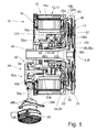
Fig. 1 eine Axialschnittdarstellung einer Antriebseinheit mit elektrischen Maschine, einer Reibungskupplung und einer Betätigungseinrichtung zur Betätigung der Kupplung; -
Fig. 2 eine stirnseitige Ansicht der Antriebseinheit vonFig. 1 mit Blick auf einen Stellantriebsmotor und eine erste Getriebeuntersetzung; -
Fig. 3 ein vergrößerter Ausschnitt ausFig. 1 mit der Ausrückanordnung der Kupplung; -
Fig. 4a eine Darstellung der Ausrückanordnung mit einer Einrichtung zum Ausgleich eines Belagverschleißes der Kupplungsreibscheibe im Neuzustand der Kupplungsreibscheibe; -
Fig. 4b die Darstellung gemäßFig. 4a in einem Verschleißzustand am Lebensdauerende der Kupplungsreibscheibe. - Die in den Figuren gezeigte Antriebseinheit 10 für ein Hybridfahrzeug umfasst zunächst ein als Elektromaschine 12 ausgebildetes Antriebsaggregat 14 mit einem Stator 16 und mit einem koaxial zu diesem um eine Drehachse A drehbar gelagerten Rotor 18. Die Elektromaschine 12 ist vorliegend als Außenläufermaschine ausgeführt und kann jedoch in Abhängigkeit von den vorliegenden Bauraumverhältnissen prinzipiell auch als Innenläufermaschine ausgebildet sein.
- Die Antriebseinheit 10 umfasst weiter eine hier in Baueinheit mit der Elektromaschine 12 ausgebildete Kupplung 20, insbesondere eine schaltbare Reibungskupplung zur Herstellung einer Drehmitnahmeverbindung des Rotors 18 mit zumindest einem weiteren Antriebselement des Fahrzeugantriebsstrangs. Der Rotor 18 umfasst einen magnetisch aktiven Abschnitt 18a mit einem Blechpaket und daran angeordneten Permanentmagneten und umfasst weiter einen hier topfförmig geformten Rotorträger 18b.
- Der Rotorträger 18b trägt zur Ausbildung der Kupplung 20 eine mit diesem drehbare, ringförmige Druckplattenbaugruppe 22, die in Richtung auf eine drehfest mit dem Rotor 18 verbundene Anpressplatte 24 verlagerbar ist. Die Druckplattenbaugruppe 22 weist dazu mehrere am Umfang verteilte axiale Fortsätze 22a auf, welche sich durch axiale Öffnungen des Rotorträgers 18b erstrecken. Zur Übertragung einer Betätigungskraft auf die Druckplattenbaugruppe 22 dient ein als Membranfeder 26 ausgebildetes Ausrückorgan 28. Die Membranfeder 26 ist an einem axialen Schneidfortsatz 30 des Rotorträgers 18b verschwenkbar gelagert und liegt mit einem radial äußeren Ringabschnitt 26a an den Fortsätzen 22a an und mit sich nach radial innen erstreckenden Federzungen 26b an einer Ausrückanordnung 32 an.
- Die Ausrückanordnung 32 ist ein Bestandteil einer Betätigungseinrichtung 34 zur Betätigung der Reibungskupplung 20, mittels der die inneren Abschnitte der Membranfederzungen 26b axial verlagerbar sind und über welche die Membranfeder 26 mittels der zuvor erläuterten Hebelanordnung die Druckplattenbaugruppe 22 axial beaufschlagen kann.
- Axial zwischen der Druckplattenbaugruppe 22 und der Anpressplatte 24 ist eine gleichfalls axial verlagerbare Reibscheibe 35 vorgesehen, die bei geschlossener Kupplung 20 ein Drehmoment der Elektromaschine 12 und/oder ein auf den Rotor 18 einleitbares Drehmoment aufnehmen kann. Zu letzterem Zweck weist die mit dem Rotor 18 verbundene oder dort ausgeführte Anpressplatte 24 eine Drehmitnahmeanordnung 38 auf. Vorliegend handelt es sich dabei um eine mit der Anpressplatte 24 verbundene Nabe 38a, welche ein Formschlussprofil 38b in der Art einer Verzahnung, insbesondere einer Stirnverzahnung trägt. Die Nabe 38 kann auf diese Weise einfach mit weiteren Elementen des Fahrzeugantriebsstranges, zum Beispiel mit einem nachfolgenden Getriebe wirkverbunden werden.
- Die Reibscheibe bzw. Kupplungsscheibe 35 steht mit einer zentral innerhalb der Elektromaschine 12 durchgeführten Antriebswelle 40 in Drehmitnahmeverbindung, welche ein Drehmoment beispielsweise auf eine Kurbelwelle eines Verbrennungsmotors des Kraftfahrzeuges weiterleiten kann. Selbstverständlich kann bei umgekehrtem Drehmomentverlauf und geschlossener Kupplung 20 ein von einem Verbrennungsmotor abgegebenes Drehmoment über die Antriebswelle 40 und die Reibscheibe 35 auf den Rotor 18 wirken und gleichzeitig über die Verbindungsanordnung an weitere, hier nicht dargestellte Antriebsstrangelemente abgegeben werden.
- Wie in
Fig. 1 zu erkennen, ist die Antriebswelle 40 im Innenraum des topfförmigen Rotorträgers 18b mittels zwei axial voneinander beabstandeten Wälzlageranordnungen 42a; 42b sowohl radial als auch axial gelagert. - Der Rotor 18 ist seinerseits mittels einer an einem Statorträger 16a festgelegten Lageranordnung 44 konzentrisch zu dem Stator 16 drehbar gelagert und gleichfalls axial zum Stator 16 festgelegt. Diese Lageranordnung 44 ist im Ausführungsbeispiel als Wälzlager 46, insbesondere als ein zweireihiges Kugellager ausgebildet, welches innerhalb eines hülsenförmigen und sich axial, zentral innerhalb des Stators 16 am Statorträger 16a erstreckenden Lagerträgers 48 aufgenommen ist.
- Radial zwischen dem Statorträger 16a und dem Lagerträger 48 ist ein ringförmiger Aufnahmeraum 17 ausgebildet, der wie nachfolgend genauer ausgeführt, zumindest einen Teil der Betätigungseinrichtung 34 zur Betätigung der Reibungskupplung 20 aufnimmt.
- Die Betätigungseinrichtung 34 umfasst einen elektrischen Stellantriebsmotor 36 mit einer quer zur Drehachse A des Antriebsaggregats 12, 14 gerichteten Stellantriebswelle 36a und die bereits erwähnte Ausrückanordnung 32. Der Stellantriebsmotor 36 ist radial außerhalb der Elektromaschine 12 angeordnet. Die Stellantriebswelle 36a verläuft axial benachbart zu dem Stator 16 und quer, insbesondere im Wesentlichen senkrecht zur Drehachse A der Elektromaschine, welche hierbei mit einer Ausrückachse B der Ausrückanordnung 32 zusammenfällt.
- Die dargestellte Antriebseinheit 10 ist zur Anordnung in einem zeichnerisch nicht dargestellten Gehäuse vorgesehen, beispielweise in einem Getriebegehäuse oder in einem davon separaten Zwischengehäuse des Fahrzeugantriebsstranges. Der Stellantriebsmotor 36 kann dabei mittels mehrerer Befestigungslaschen 36b an der Außenseite des Gehäuses festgelegt werden.
- Die Ausrückanordnung 32 steht mit der Stellantriebswelle 36a in Wirkverbindung und ist dazu ausgebildet, eine Rotationsbewegung der Stellantriebswelle 36a in eine auf das Ausrückorgan 28 der Kupplung 20 wirkende Translationsbewegung zu überführen.
- Zu diesem Zweck umfasst die Ausrückanordnung 32 ein drehbares und axial zum Ausrückorgan 28 festgelegtes Eingangselement 32a und ein zu diesem axial verlagerbares Ausgangselement 32b, welches zur Drehentkopplung über ein Ausrücklager 36c mit dem Ausrückorgan 28, d.h. der Membranfeder 26 in Wirkverbindung steht. Im Ausführungsbeispiel ist die Ausrückanordnung 32 als Kugelrampentrieb ausgeführt, wobei zwischen dem Eingangselement 32a und dem Ausgangselement 32b in Rampen geführte Kugeln laufen.
- Die Ausrückanordnung 32 weist weiter eine Einrichtung 60 zum Ausgleich eines Belagverschleißes der Reibscheibe 35 auf, welche unabhängig von einem Verschleißgrad der Reibscheibe 35 den ständigen Anlagekontakt der Membranfeder 26 an dem Ausrücklager 36c bewirkt. Zu diesem Zweck umfasst das Ausgangselement 32b einen mittels Führungsbolzen 32e zu einem Grundkörper 32c axial verlagerbaren Lagerträger 32d, welcher das Ausrücklager 36c mit einem seiner Lagerringe 36f, hier dem äußeren Lagerring 36f aufnimmt. Der andere, mit der Kupplung 20 umlaufende Lagerring 36g liegt über eine Anlagescheibe 36h an den freien Enden der Federzungen 26b an. Der axiale Bewegungsraum des Lagerträgers 32d ist einerseits in Richtung der Kupplung 20 durch einen Anschlag am Führungsbolzen 32e und andererseits in der entgegengesetzten Richtung durch einen Anschlag am Grundkörper 32c eingeschränkt. Axial zwischen dem Lagerträger 32d und dem Grundkörper 32c ist eine elastisches Element 32i, hier eine Tellerfeder eingespannt, welche den Lagerträger 32d in Richtung der Membranfeder 26 belastet und das Ausrücklager 36c mittels der Anlagescheibe 36h an den Membranfederzungen 26b zur Anlage bringt. Der Lagerträger 32d ist somit im unverschlissenen Neuzustand der Reibscheibe 35 gegenüber dem Grundkörper 32c des Ausgangselements 32b um einen Wegbetrag verschoben, welcher vorzugsweise zumindest gleich oder größer einem nachfolgend erläuterten Ausrück-Verschleißweg x ist.
- Mit zunehmendem Verschleiß der Reibscheibe 35 verlagern sich die freien Enden der Federzungen 26b im geschlossenem Zustand der Kupplung 20 axial in Richtung der Ausrückanordnung 32, wobei der Betrag dieser Verlagerung vom Neuzustand bis zum Lebensdauerende der Reibscheibe 35 den Ausrück-Verschleißweg x darstellt. Mit steigendem Verschleiß wird in Bezug zum geschlossenen, d.h. unbetätigten Zustand der Kupplung 20 das Ausrücklager 36c unter Überwindung der Federkraft des elastischen Elements 32i in Richtung des Grundkörpers 32c verlagert bis der Ausrück-Verschleißweg x aufgebraucht ist und dessen Lagerträger 32d am Grundkörper 32c zur Anlage kommt.
- Hinsichtlich der Einleitung einer Betätigungskraft sind das elastische Element 32i und die Membranfeder 26 in Reihe geschaltet, sodass bei einer Betätigung der Kupplung 20 zunächst der vom aktuellen Verschleißzustand jeweils vorhandene restliche Verschleißweg unter Spannung des elastischen Elements 32i überwunden bzw. aufgebraucht wird und wobei erst danach die Membranfeder 26 verschwenkt wird.
- Zur Erzeugung einer Drehzahluntersetzung bzw. einer Drehmomentübersetzung ist zwischen der Stellantriebswelle 36a und der Ausrückanordnung 32 ein Untersetzungsgetriebe 50 mit zumindest einer ersten und einer zweiten Getriebestufe 50a; 50 b angeordnet. Die erste Getriebestufe 50a des Untersetzungsgetriebes 50 ist durch ein Schneckengetriebe realisiert, wozu die Stellantriebswelle 36a selbst bzw. hier ein mit dieser verbundener oder verbindbarer Antriebswellenabschnitt eine Schnecke 52 umfasst, welche mit einem Schneckenrad 54 zusammenwirkt. Das Schneckenrad 54 ist zweifach gelagert und dazu am Statorträger 16a und an einem Getriebegehäuse 50c drehbar angeordnet.
- Die zweite Getriebestufe 50b umfasst ein Stirnradgetriebe aus einer Paarung von zwei Stirnrädern 56; 58. Ein erstes Stirnrad 56 ist dabei in Baueinheit gemeinsam mit dem Schneckenrad 54 angeordnet. Das zweite Stirnrad 58 ist am Eingangselement 32a der Ausrückanordnung 32 ausgebildet und mit diesem drehbar auf dem Lagerträger 48 positioniert. Das Untersetzungsgetriebe 50 und die Ausrückanordnung 32 sind somit am Statorträger 16a abgestützt angeordnet. Die erste Getriebestufe 50a befindet sich axial unmittelbar benachbart zur Elektromaschine 12, während die zweite Getriebestufe 50b und die Ausrückanordnung 32 innerhalb des Aufnahmeraums 17 angeordnet sind.
- Durch das Zusammenspiel der beiden Getriebestufen 50a, b mit einer zusätzlichen Übersetzung der Ausrückanordnung 32 selbst , d.h. bei der Wandlung der Drehbewegung in die Translationsbewegung, kann insgesamt eine nichtlineare Charakteristik der Betätigungseinrichtung 34 erzeugt werden, wobei ein axialer Stellweg des Ausgangselementes 32b der Ausrückanordnung 32 sich nichtlinear zu einem Drehwinkel der Stellantriebswelle 36a verhält. Der nichtlineare Beitrag wird insbesondere durch eine entsprechende Ausgestaltung der Ausrückanordnung 32, hier des Kugelrampenantriebs, erzeugt. Alternativ kann auch insgesamt eine lineare Charakteristik der Betätigungseinrichtung 34 dargestellt werden.
- Des Weiteren können die zwischen den Elementen der Betätigungseinrichtung 34 wirkenden Reibkräfte so groß gewählt werden, dass bei aktivierter Betätigungseinrichtung 34, im Ausführungsbeispiel bei ausgerückter Kupplung 20, eine selbsttätige Rückstellung unterbleibt, das heißt, dass die Betätigungseinrichtung 34 selbsthemmend ausgeführt ist.
- Es kann alternativ jedoch ebenso beispielsweise aus sicherheitstechnischen Aspekten von Vorteil sein, die Reibung der Betätigungseinrichtung 34 zur Erzielung einer selbsttätigen Rückstellung zu minimieren, wobei die erforderliche Rückstellkraft durch die im Ausrückorgan 28 selbst oder durch die in separaten Rückstellfedern bei einem Betätigungsvorgang gespeicherte Energie bereitgestellt wird. Dazu kann z.B. eine geeignete Wahl der Schneckenpaarauslegung, d.h. der Schnecke 52 und des Schneckenrades 54 vorgenommen werden. Ohne Bestromung des Stellantriebsmotors 36 geht die Kupplung 20 in ihren Normalzustand über, der vorliegend als ein normal-geschlossen-Zustand ausgeführt ist.
- Der Stellantriebsmotor kann alternativ auch innerhalb der radialen Erstreckung der Elektromaschine angeordnet werden, wo dieser vor äußeren Einflüssen geschützt ist und wobei lediglich die elektrischen Zuleitungen an diesen herangeführt werden brauchen.
-
- 10
- Antriebseinheit
- 12
- Elektromaschine
- 14
- Antriebsaggregat
- 16
- Stator
- 16a
- Statorträger
- 17
- Aufnahmeraum
- 18
- Rotor
- 18a
- magnetisch aktiver Abschnitt
- 18b
- Rotorträger
- 20
- Kupplung
- 22
- Druckplattenbaugruppe
- 22a
- axiale Fortsätze
- 24
- Anpresspatte
- 26
- Membranfeder
- 26a
- Ringabschnitt
- 26b
- Federzungen
- 28
- Ausrückorgan
- 30
- Schneidfortsatz
- 32
- Ausrückanordnung
- 32a
- Eingangselement
- 32b
- Ausgangselement
- 32c
- Grundkörper
- 32d
- Lagerträger
- 32e
- Führungsbolzen
- 32i
- elastisches Element
- 34
- Betätigungseinrichtung
- 35
- Reibscheibe
- 36
- Stellantriebsmotor
- 36a
- Stellantriebswelle
- 36b
- Befestigungslaschen
- 36c
- Ausrücklager
- 36f
- feststehender Lagerring
- 36g
- umlaufender Lagerring
- 36h
- Anlagescheibe
- 38
- Drehmitnahmeanordnung
- 38a
- Nabe
- 38b
- Formschlussprofil
- 40
- Antriebswelle
- 42a,b
- Wälzlager
- 44
- Lageranordnung
- 46
- Wälzlager
- 48
- Lagerträger
- 50
- Untersetzungsgetriebe
- 50a,b
- Getriebestufe
- 50c
- Getriebegehäuse
- 52
- Schnecke
- 54
- Schneckenrad
- 56
- Stirnrad
- 58
- Stirnrad
- 60
- Verschleißausgleichseinrichtung
- A
- Drehachse
- B
- Ausrückachse
Claims (12)
- Antriebseinheit (10) für ein Kraftfahrzeug umfassend- ein als Elektromaschine (12) ausgebildetes Antriebsaggregat (14) mit einem Stator (16) und mit einem koaxial zu diesem um eine Drehachse A drehbar gelagerten Rotor (18),- eine schaltbare Kupplung (20) zur Herstellung einer Drehmitnahmeverbindung des Rotors (18) mit einem Antriebselement (40), wobei- die Kupplung (20) ein Ausrückorgan (28) aufweist, welches mittels einer Betätigungseinrichtung (34) axial verlagerbar ist und wobei die Betätigungseinrichtung (34) zumindest teilweise einem von dem Stator (16) umschlossenen Aufnahmeraum (17) angeordnet ist,
dadurch gekennzeichnet, dass die Betätigungseinrichtung (34) umfasst- einen elektrischen Stellantriebsmotor (36) mit einer Stellantriebswelle (36a) und- eine mit der Stellantriebswelle (36a) in Wirkverbindung stehende Ausrückanordnung (32), welche eine Rotationsbewegung der Stellantriebswelle (36a) in eine auf das Ausrückorgan (28) der Kupplung (20) wirkende Translationsbewegung überführt und wobei- die Ausrückanordnung (32) ein drehbares und axial zum Ausrückorgan (28) festgelegtes Eingangselement (32a) und ein zu diesem axial verlagerbares Ausgangselement (32b) umfasst, welches mit dem Ausrückorgan (28) in Wirkverbindung steht. - Antriebseinheit nach Anspruch 1, dadurch gekennzeichnet, dass zwischen der Stellantriebswelle (36a) und der Ausrückanordnung (32) ein Untersetzungsgetriebe (50) angeordnet ist.
- Antriebseinheit nach Anspruch 2, dadurch gekennzeichnet, dass das Untersetzungsgetriebe (50) mit einer ersten und einer zweiten Getriebestufe (50a); (50b) ausgeführt ist.
- Antriebseinheit nach einem der Ansprüche 1 bis 3, dadurch gekennzeichnet, dass ein axialer Stellweg des Ausgangselementes (32b) der Ausrückanordnung (32) sich nichtlinear zu einem Drehwinkel der Stellantriebswelle (36a) verhält.
- Antriebseinheit nach einem der Ansprüche 1 bis 4, dadurch gekennzeichnet, dass die Ausrückanordnung (32) als Kugelrampentrieb ausgeführt ist.
- Antriebseinheit nach einem der Ansprüche 2 bis 5, dadurch gekennzeichnet, dass eine erste Getriebestufe (50a) des Untersetzungsgetriebes (50) ein Schneckengetriebe umfasst.
- Antriebseinheit nach einem der Ansprüche 2 bis 6, dadurch gekennzeichnet, dass eine zweite Getriebestufe (50b) des Untersetzungsgetriebes (50) ein Stirnradgetriebe umfasst ist.
- Antriebseinheit nach einem der Ansprüche 1 bis 7, dadurch gekennzeichnet, dass die Betätigungseinrichtung (34) selbsthemmend ausgeführt ist.
- Antriebseinheit nach einem der Ansprüche 1 bis 7, dadurch gekennzeichnet, dass die Betätigungseinrichtung (34) selbstrückstellend ausgeführt ist.
- Antriebseinheit nach einem der Ansprüche 1 bis 8 oder 9, dadurch gekennzeichnet, dass die Stellantriebswelle (36a) quer zur Drehachse A des Antriebsaggregats (14) gerichtet ist und axial benachbart zu dem Stator (16) verläuft und dass der Stellantriebsmotor (36) radial außerhalb der elektrischen Maschine (12) angeordnet ist.
- Antriebseinheit nach einem der Ansprüche 1 bis 10, dadurch gekennzeichnet, dass die Betätigungseinrichtung (34) zumindest mittelbar am Stator (16) der elektrischen Maschine festgelegt ist.
- Antriebseinheit nach einem der Ansprüche 1-11, dadurch gekennzeichnet, dass die Ausrückanordnung 32 eine Einrichtung 60 zum Ausgleich eines Belagverschleißes der Reibscheibe 35 aufweist.
Applications Claiming Priority (1)
| Application Number | Priority Date | Filing Date | Title |
|---|---|---|---|
| DE102012216601.7A DE102012216601A1 (de) | 2012-09-18 | 2012-09-18 | Antriebseinheit für ein Kraftfahrzeug mit einer elektrischen Maschine und einer Kupplung |
Publications (3)
| Publication Number | Publication Date |
|---|---|
| EP2708768A2 true EP2708768A2 (de) | 2014-03-19 |
| EP2708768A3 EP2708768A3 (de) | 2014-06-11 |
| EP2708768B1 EP2708768B1 (de) | 2019-03-20 |
Family
ID=49035322
Family Applications (1)
| Application Number | Title | Priority Date | Filing Date |
|---|---|---|---|
| EP13180797.6A Not-in-force EP2708768B1 (de) | 2012-09-18 | 2013-08-19 | Antriebseinheit für ein kraftfahrzeug mit einer elektrischen maschine und einer kupplung |
Country Status (4)
| Country | Link |
|---|---|
| US (1) | US9479027B2 (de) |
| EP (1) | EP2708768B1 (de) |
| CN (1) | CN103660907B (de) |
| DE (1) | DE102012216601A1 (de) |
Cited By (4)
| Publication number | Priority date | Publication date | Assignee | Title |
|---|---|---|---|---|
| WO2016055236A1 (de) * | 2014-10-09 | 2016-04-14 | Zf Friedrichshafen Ag | Antriebseinheit für ein hybridmodul |
| CN106255608A (zh) * | 2014-05-08 | 2016-12-21 | Zf腓特烈斯哈芬股份公司 | 用于具有电机和离合器操纵装置的机动车的结构单元 |
| DE102015220998A1 (de) | 2015-10-27 | 2017-04-27 | Zf Friedrichshafen Ag | Elektrische Antriebseinheit für einen Antriebsstrang eines Fahrzeugs |
| DE102015220993A1 (de) | 2015-10-27 | 2017-04-27 | Zf Friedrichshafen Ag | Zusammenbaueinheit für eine elektrische Antriebseinheit innerhalb eines Antriebsstrangs eines Fahrzeugs |
Families Citing this family (15)
| Publication number | Priority date | Publication date | Assignee | Title |
|---|---|---|---|---|
| US9803716B2 (en) * | 2013-04-22 | 2017-10-31 | Dana Limited | Torsional compensator based on magnetic reluctance |
| DE102013219247A1 (de) | 2013-09-25 | 2015-03-26 | Zf Friedrichshafen Ag | Baueinheit mit einer elektrischen Maschine |
| DE102014212928A1 (de) * | 2014-07-03 | 2016-01-21 | Zf Friedrichshafen Ag | Antriebseinheit für ein Kraftfahrzeug |
| DE102014222592A1 (de) * | 2014-09-08 | 2016-03-10 | Sms Group Gmbh | Antrieb einer Maschine, Drehmomentmotor, Kupplungseinrichtung, Vorrichtung zum Bearbeiten von Werkstoffen und Verwendung eines Torquemotors |
| DE102015205689A1 (de) * | 2015-03-30 | 2016-10-06 | Robert Bosch Gmbh | Schutzvorrichtung zumindest zu einem Schutz eines Bedieners bei einem unbeherrschten Blockierfall einer Handwerkzeugmaschine |
| DE102015121138A1 (de) | 2015-12-04 | 2017-06-08 | Dr. Ing. H.C. F. Porsche Aktiengesellschaft | Einrichtung zum Betätigen einer Kupplung |
| CN107139711B (zh) * | 2016-03-01 | 2022-01-11 | 舍弗勒技术股份两合公司 | 用于混合动力汽车的动力耦合装置 |
| FR3052401B1 (fr) * | 2016-06-09 | 2019-08-16 | Valeo Embrayages | Dispositif de transmission de couple, notamment pour vehicule automobile |
| TWI632306B (zh) * | 2016-09-10 | 2018-08-11 | 本土股份有限公司 | Clutch structure |
| US10511207B2 (en) | 2017-03-21 | 2019-12-17 | Borgwarner Inc. | Compact electric machine with combined rotor carrier and clutch housing |
| DE102017211809A1 (de) | 2017-07-11 | 2019-01-17 | Zf Friedrichshafen Ag | Antriebseinheit für ein Kraftfahrzeug mit einer elektrischen Maschine und einer Kupplung |
| CN111247350A (zh) * | 2017-07-22 | 2020-06-05 | 特斯平轴承有限公司 | 自对准离合器分离轴承 |
| JP7205394B2 (ja) | 2018-07-06 | 2023-01-17 | 株式会社デンソー | クラッチ装置 |
| WO2020009187A1 (ja) | 2018-07-06 | 2020-01-09 | 株式会社デンソー | クラッチ装置 |
| JP2026011286A (ja) * | 2024-07-11 | 2026-01-23 | スズキ株式会社 | ハイブリッド車両の動力伝達装置 |
Citations (2)
| Publication number | Priority date | Publication date | Assignee | Title |
|---|---|---|---|---|
| EP0716242B1 (de) | 1994-12-08 | 1998-06-03 | Adam Opel Ag | Elektromotorische Betätigung einer Reibscheibenkupplung |
| EP2148107B1 (de) | 2008-07-25 | 2010-08-25 | ZF Friedrichshafen AG | Antriebseinheit für ein Hybridfahrzeug und Verfahren zu deren Montage |
Family Cites Families (12)
| Publication number | Priority date | Publication date | Assignee | Title |
|---|---|---|---|---|
| JP2573802Y2 (ja) * | 1990-07-27 | 1998-06-04 | 自動車電機工業株式会社 | アクチュエータ |
| DE19729997C2 (de) * | 1996-10-02 | 2000-06-21 | Mannesmann Sachs Ag | Stelleinrichtung für die Betätigung einer Reibungskupplung |
| US5964330A (en) | 1997-09-30 | 1999-10-12 | Eaton Corporation | Ball ramp driveline clutch actuator with self aligning cone clutch |
| US6851537B2 (en) * | 2003-03-07 | 2005-02-08 | Magna Drivetrain Of America, Inc. | Worm driven ball screw actuator for traction clutches |
| US6771031B1 (en) * | 2003-05-08 | 2004-08-03 | General Motors Corporation | Control method for an electric motor-activated clutch mechanism |
| AT7524U1 (de) * | 2003-10-31 | 2005-04-25 | Magna Steyr Fahrzeugtechnik Ag | Aktuator mit einem elektrischen stellmotor und steuerbare reibungskupplung mit einem solchen |
| TWI287513B (en) * | 2005-12-19 | 2007-10-01 | Ind Tech Res Inst | Hybrid power system for vehicle |
| DE102006015688A1 (de) * | 2006-03-27 | 2007-10-04 | Getrag Getriebe- Und Zahnradfabrik Hermann Hagenmeyer Gmbh & Cie Kg | Aktuatoranordnung und Schaltkupplungsanordnung |
| DE102006051287A1 (de) * | 2006-10-26 | 2008-04-30 | Getrag Getriebe- Und Zahnradfabrik Hermann Hagenmeyer Gmbh & Cie Kg | Aktuatoranordnung für eine Kraftfahrzeugkupplung |
| KR100957151B1 (ko) * | 2008-03-17 | 2010-05-11 | 현대자동차주식회사 | 클러치 액츄에이터 |
| GB2477121A (en) * | 2010-01-22 | 2011-07-27 | Gm Global Tech Operations Inc | Self-locking electromechanical clutch actuator having a worm gear |
| DE102010043117A1 (de) * | 2010-10-29 | 2012-05-03 | Zf Friedrichshafen Ag | Antriebseinheit mit einer Elektromaschine und einer Kupplung |
-
2012
- 2012-09-18 DE DE102012216601.7A patent/DE102012216601A1/de not_active Withdrawn
-
2013
- 2013-08-19 EP EP13180797.6A patent/EP2708768B1/de not_active Not-in-force
- 2013-08-28 CN CN201310394512.6A patent/CN103660907B/zh not_active Expired - Fee Related
- 2013-09-17 US US14/028,598 patent/US9479027B2/en not_active Expired - Fee Related
Patent Citations (2)
| Publication number | Priority date | Publication date | Assignee | Title |
|---|---|---|---|---|
| EP0716242B1 (de) | 1994-12-08 | 1998-06-03 | Adam Opel Ag | Elektromotorische Betätigung einer Reibscheibenkupplung |
| EP2148107B1 (de) | 2008-07-25 | 2010-08-25 | ZF Friedrichshafen AG | Antriebseinheit für ein Hybridfahrzeug und Verfahren zu deren Montage |
Cited By (7)
| Publication number | Priority date | Publication date | Assignee | Title |
|---|---|---|---|---|
| CN106255608A (zh) * | 2014-05-08 | 2016-12-21 | Zf腓特烈斯哈芬股份公司 | 用于具有电机和离合器操纵装置的机动车的结构单元 |
| CN106255608B (zh) * | 2014-05-08 | 2019-07-30 | Zf腓特烈斯哈芬股份公司 | 用于具有电机和离合器操纵装置的机动车的结构单元 |
| WO2016055236A1 (de) * | 2014-10-09 | 2016-04-14 | Zf Friedrichshafen Ag | Antriebseinheit für ein hybridmodul |
| DE102015220998A1 (de) | 2015-10-27 | 2017-04-27 | Zf Friedrichshafen Ag | Elektrische Antriebseinheit für einen Antriebsstrang eines Fahrzeugs |
| DE102015220993A1 (de) | 2015-10-27 | 2017-04-27 | Zf Friedrichshafen Ag | Zusammenbaueinheit für eine elektrische Antriebseinheit innerhalb eines Antriebsstrangs eines Fahrzeugs |
| WO2017071892A1 (de) | 2015-10-27 | 2017-05-04 | Zf Friedrichshafen Ag | Zusammenbaueinheit für eine elektrische antriebseinheit innerhalb eines antriebsstrangs eines fahrzeugs |
| WO2017071893A1 (de) * | 2015-10-27 | 2017-05-04 | Zf Friedrichshafen Ag | Elektrische antriebseinheit für einen antriebsstrang eines fahrzeugs |
Also Published As
| Publication number | Publication date |
|---|---|
| EP2708768B1 (de) | 2019-03-20 |
| US9479027B2 (en) | 2016-10-25 |
| EP2708768A3 (de) | 2014-06-11 |
| CN103660907A (zh) | 2014-03-26 |
| DE102012216601A1 (de) | 2014-03-20 |
| US20140077641A1 (en) | 2014-03-20 |
| CN103660907B (zh) | 2017-08-11 |
Similar Documents
| Publication | Publication Date | Title |
|---|---|---|
| EP2708768B1 (de) | Antriebseinheit für ein kraftfahrzeug mit einer elektrischen maschine und einer kupplung | |
| DE112016005194B4 (de) | Aktor | |
| DE102015220920B4 (de) | Baugruppe mit einer Reibeinrichtung | |
| DE102015217164B4 (de) | Baugruppe mit einer Reibeinrichtung | |
| WO2009109241A1 (de) | Betätigungsanordnung für schaltelemente eines getriebes | |
| DE102016113117A1 (de) | Elektrischer Stellantrieb und Stellgerät mit einem elektrischen Stellantrieb | |
| DE102021203008A1 (de) | Betätigungseinrichtung für eine elektromechanisch betätigbare Kraftfahrzeugbremse | |
| WO2023138717A1 (de) | Radentkopplungsvorrichtung für ein kraftfahrzeug in bistabiler ausführung | |
| DE102010018000A1 (de) | Drehmomenteinstellvorrichtung | |
| EP2554868B2 (de) | Ausrücksystem | |
| DE102011006965A1 (de) | Vorrichtung zum Verändern eines Betriebszustandes eines Schaltelementes mit zwei Schaltelementen | |
| DE102015100906B4 (de) | Synchronisiereinrichtung, Kupplungsanordnung und Antriebsanordnung | |
| DE102015200484B4 (de) | Reibkupplung mit Wälzkörper-abgestützter Anpressplatte | |
| DE102015224801A1 (de) | Aktorvorrichtung zur Betätigung einer Kraftfahrzeugkomponente | |
| EP3059402A1 (de) | Vorrichtung zur phasenverschiebung des drehwinkels eines antriebsteils zu einem abtriebsteil | |
| DE102015220680A1 (de) | Baugruppe mit einer Reibeinrichtung | |
| DE102006042477A1 (de) | Elektromotorischer Aktuator zur Auslenkung eines Kraftfahrzeugteils | |
| WO2018086653A1 (de) | Doppelschlingfeder, rotationseinrichtung und zu aktuierendes system | |
| DE102013214502A1 (de) | Direktbetätigte Trennkupplung für Hybrid-Antriebssysteme | |
| DE102015204504B4 (de) | Baugruppe, insbesondere Aktor mit einer Reibeinrichtung | |
| DE102014216618A1 (de) | Magnetohydrodynamischer Schraubenaktor mit internem Volumenausgleich | |
| DE102006030032A1 (de) | Vorrichtung zur Betätigung eines Stell- oder Schaltelementes | |
| DE102006042478A1 (de) | Elektromotorischer Aktuator zur Auslenkung eines mechanischen Teils | |
| DE102019115904A1 (de) | Hybridmodul mit Trennkupplung und Betätigungseinheit ohne Kompensation; sowie Antriebsstrang | |
| EP2786036B1 (de) | Bremsanordnung |
Legal Events
| Date | Code | Title | Description |
|---|---|---|---|
| PUAI | Public reference made under article 153(3) epc to a published international application that has entered the european phase |
Free format text: ORIGINAL CODE: 0009012 |
|
| AK | Designated contracting states |
Kind code of ref document: A2 Designated state(s): AL AT BE BG CH CY CZ DE DK EE ES FI FR GB GR HR HU IE IS IT LI LT LU LV MC MK MT NL NO PL PT RO RS SE SI SK SM TR |
|
| AX | Request for extension of the european patent |
Extension state: BA ME |
|
| PUAL | Search report despatched |
Free format text: ORIGINAL CODE: 0009013 |
|
| AK | Designated contracting states |
Kind code of ref document: A3 Designated state(s): AL AT BE BG CH CY CZ DE DK EE ES FI FR GB GR HR HU IE IS IT LI LT LU LV MC MK MT NL NO PL PT RO RS SE SI SK SM TR |
|
| AX | Request for extension of the european patent |
Extension state: BA ME |
|
| RIC1 | Information provided on ipc code assigned before grant |
Ipc: F16D 23/14 20060101ALI20140506BHEP Ipc: B60K 6/387 20071001ALI20140506BHEP Ipc: F16D 28/00 20060101AFI20140506BHEP |
|
| 17P | Request for examination filed |
Effective date: 20141209 |
|
| GRAP | Despatch of communication of intention to grant a patent |
Free format text: ORIGINAL CODE: EPIDOSNIGR1 |
|
| STAA | Information on the status of an ep patent application or granted ep patent |
Free format text: STATUS: GRANT OF PATENT IS INTENDED |
|
| INTG | Intention to grant announced |
Effective date: 20181031 |
|
| GRAS | Grant fee paid |
Free format text: ORIGINAL CODE: EPIDOSNIGR3 |
|
| RIC1 | Information provided on ipc code assigned before grant |
Ipc: F16D 28/00 20060101AFI20140506BHEP Ipc: B60K 6/387 20071001ALI20140506BHEP Ipc: F16D 23/14 20060101ALI20140506BHEP |
|
| GRAA | (expected) grant |
Free format text: ORIGINAL CODE: 0009210 |
|
| STAA | Information on the status of an ep patent application or granted ep patent |
Free format text: STATUS: THE PATENT HAS BEEN GRANTED |
|
| AK | Designated contracting states |
Kind code of ref document: B1 Designated state(s): AL AT BE BG CH CY CZ DE DK EE ES FI FR GB GR HR HU IE IS IT LI LT LU LV MC MK MT NL NO PL PT RO RS SE SI SK SM TR |
|
| REG | Reference to a national code |
Ref country code: GB Ref legal event code: FG4D Free format text: NOT ENGLISH |
|
| REG | Reference to a national code |
Ref country code: CH Ref legal event code: EP |
|
| REG | Reference to a national code |
Ref country code: DE Ref legal event code: R096 Ref document number: 502013012445 Country of ref document: DE |
|
| REG | Reference to a national code |
Ref country code: AT Ref legal event code: REF Ref document number: 1110878 Country of ref document: AT Kind code of ref document: T Effective date: 20190415 |
|
| REG | Reference to a national code |
Ref country code: IE Ref legal event code: FG4D Free format text: LANGUAGE OF EP DOCUMENT: GERMAN |
|
| REG | Reference to a national code |
Ref country code: NL Ref legal event code: MP Effective date: 20190320 |
|
| PG25 | Lapsed in a contracting state [announced via postgrant information from national office to epo] |
Ref country code: SE Free format text: LAPSE BECAUSE OF FAILURE TO SUBMIT A TRANSLATION OF THE DESCRIPTION OR TO PAY THE FEE WITHIN THE PRESCRIBED TIME-LIMIT Effective date: 20190320 Ref country code: NO Free format text: LAPSE BECAUSE OF FAILURE TO SUBMIT A TRANSLATION OF THE DESCRIPTION OR TO PAY THE FEE WITHIN THE PRESCRIBED TIME-LIMIT Effective date: 20190620 Ref country code: LT Free format text: LAPSE BECAUSE OF FAILURE TO SUBMIT A TRANSLATION OF THE DESCRIPTION OR TO PAY THE FEE WITHIN THE PRESCRIBED TIME-LIMIT Effective date: 20190320 Ref country code: FI Free format text: LAPSE BECAUSE OF FAILURE TO SUBMIT A TRANSLATION OF THE DESCRIPTION OR TO PAY THE FEE WITHIN THE PRESCRIBED TIME-LIMIT Effective date: 20190320 |
|
| REG | Reference to a national code |
Ref country code: LT Ref legal event code: MG4D |
|
| PG25 | Lapsed in a contracting state [announced via postgrant information from national office to epo] |
Ref country code: GR Free format text: LAPSE BECAUSE OF FAILURE TO SUBMIT A TRANSLATION OF THE DESCRIPTION OR TO PAY THE FEE WITHIN THE PRESCRIBED TIME-LIMIT Effective date: 20190621 Ref country code: BG Free format text: LAPSE BECAUSE OF FAILURE TO SUBMIT A TRANSLATION OF THE DESCRIPTION OR TO PAY THE FEE WITHIN THE PRESCRIBED TIME-LIMIT Effective date: 20190620 Ref country code: NL Free format text: LAPSE BECAUSE OF FAILURE TO SUBMIT A TRANSLATION OF THE DESCRIPTION OR TO PAY THE FEE WITHIN THE PRESCRIBED TIME-LIMIT Effective date: 20190320 Ref country code: HR Free format text: LAPSE BECAUSE OF FAILURE TO SUBMIT A TRANSLATION OF THE DESCRIPTION OR TO PAY THE FEE WITHIN THE PRESCRIBED TIME-LIMIT Effective date: 20190320 Ref country code: RS Free format text: LAPSE BECAUSE OF FAILURE TO SUBMIT A TRANSLATION OF THE DESCRIPTION OR TO PAY THE FEE WITHIN THE PRESCRIBED TIME-LIMIT Effective date: 20190320 Ref country code: LV Free format text: LAPSE BECAUSE OF FAILURE TO SUBMIT A TRANSLATION OF THE DESCRIPTION OR TO PAY THE FEE WITHIN THE PRESCRIBED TIME-LIMIT Effective date: 20190320 |
|
| PG25 | Lapsed in a contracting state [announced via postgrant information from national office to epo] |
Ref country code: SK Free format text: LAPSE BECAUSE OF FAILURE TO SUBMIT A TRANSLATION OF THE DESCRIPTION OR TO PAY THE FEE WITHIN THE PRESCRIBED TIME-LIMIT Effective date: 20190320 Ref country code: CZ Free format text: LAPSE BECAUSE OF FAILURE TO SUBMIT A TRANSLATION OF THE DESCRIPTION OR TO PAY THE FEE WITHIN THE PRESCRIBED TIME-LIMIT Effective date: 20190320 Ref country code: RO Free format text: LAPSE BECAUSE OF FAILURE TO SUBMIT A TRANSLATION OF THE DESCRIPTION OR TO PAY THE FEE WITHIN THE PRESCRIBED TIME-LIMIT Effective date: 20190320 Ref country code: EE Free format text: LAPSE BECAUSE OF FAILURE TO SUBMIT A TRANSLATION OF THE DESCRIPTION OR TO PAY THE FEE WITHIN THE PRESCRIBED TIME-LIMIT Effective date: 20190320 Ref country code: IT Free format text: LAPSE BECAUSE OF FAILURE TO SUBMIT A TRANSLATION OF THE DESCRIPTION OR TO PAY THE FEE WITHIN THE PRESCRIBED TIME-LIMIT Effective date: 20190320 Ref country code: ES Free format text: LAPSE BECAUSE OF FAILURE TO SUBMIT A TRANSLATION OF THE DESCRIPTION OR TO PAY THE FEE WITHIN THE PRESCRIBED TIME-LIMIT Effective date: 20190320 Ref country code: AL Free format text: LAPSE BECAUSE OF FAILURE TO SUBMIT A TRANSLATION OF THE DESCRIPTION OR TO PAY THE FEE WITHIN THE PRESCRIBED TIME-LIMIT Effective date: 20190320 Ref country code: PT Free format text: LAPSE BECAUSE OF FAILURE TO SUBMIT A TRANSLATION OF THE DESCRIPTION OR TO PAY THE FEE WITHIN THE PRESCRIBED TIME-LIMIT Effective date: 20190720 |
|
| PG25 | Lapsed in a contracting state [announced via postgrant information from national office to epo] |
Ref country code: SM Free format text: LAPSE BECAUSE OF FAILURE TO SUBMIT A TRANSLATION OF THE DESCRIPTION OR TO PAY THE FEE WITHIN THE PRESCRIBED TIME-LIMIT Effective date: 20190320 Ref country code: PL Free format text: LAPSE BECAUSE OF FAILURE TO SUBMIT A TRANSLATION OF THE DESCRIPTION OR TO PAY THE FEE WITHIN THE PRESCRIBED TIME-LIMIT Effective date: 20190320 |
|
| PG25 | Lapsed in a contracting state [announced via postgrant information from national office to epo] |
Ref country code: IS Free format text: LAPSE BECAUSE OF FAILURE TO SUBMIT A TRANSLATION OF THE DESCRIPTION OR TO PAY THE FEE WITHIN THE PRESCRIBED TIME-LIMIT Effective date: 20190720 |
|
| REG | Reference to a national code |
Ref country code: DE Ref legal event code: R097 Ref document number: 502013012445 Country of ref document: DE |
|
| PLBE | No opposition filed within time limit |
Free format text: ORIGINAL CODE: 0009261 |
|
| STAA | Information on the status of an ep patent application or granted ep patent |
Free format text: STATUS: NO OPPOSITION FILED WITHIN TIME LIMIT |
|
| PG25 | Lapsed in a contracting state [announced via postgrant information from national office to epo] |
Ref country code: DK Free format text: LAPSE BECAUSE OF FAILURE TO SUBMIT A TRANSLATION OF THE DESCRIPTION OR TO PAY THE FEE WITHIN THE PRESCRIBED TIME-LIMIT Effective date: 20190320 |
|
| 26N | No opposition filed |
Effective date: 20200102 |
|
| PG25 | Lapsed in a contracting state [announced via postgrant information from national office to epo] |
Ref country code: SI Free format text: LAPSE BECAUSE OF FAILURE TO SUBMIT A TRANSLATION OF THE DESCRIPTION OR TO PAY THE FEE WITHIN THE PRESCRIBED TIME-LIMIT Effective date: 20190320 |
|
| PG25 | Lapsed in a contracting state [announced via postgrant information from national office to epo] |
Ref country code: TR Free format text: LAPSE BECAUSE OF FAILURE TO SUBMIT A TRANSLATION OF THE DESCRIPTION OR TO PAY THE FEE WITHIN THE PRESCRIBED TIME-LIMIT Effective date: 20190320 |
|
| GBPC | Gb: european patent ceased through non-payment of renewal fee |
Effective date: 20190819 |
|
| PG25 | Lapsed in a contracting state [announced via postgrant information from national office to epo] |
Ref country code: CH Free format text: LAPSE BECAUSE OF NON-PAYMENT OF DUE FEES Effective date: 20190831 Ref country code: MC Free format text: LAPSE BECAUSE OF FAILURE TO SUBMIT A TRANSLATION OF THE DESCRIPTION OR TO PAY THE FEE WITHIN THE PRESCRIBED TIME-LIMIT Effective date: 20190320 Ref country code: LI Free format text: LAPSE BECAUSE OF NON-PAYMENT OF DUE FEES Effective date: 20190831 Ref country code: LU Free format text: LAPSE BECAUSE OF NON-PAYMENT OF DUE FEES Effective date: 20190819 |
|
| REG | Reference to a national code |
Ref country code: BE Ref legal event code: MM Effective date: 20190831 |
|
| PG25 | Lapsed in a contracting state [announced via postgrant information from national office to epo] |
Ref country code: IE Free format text: LAPSE BECAUSE OF NON-PAYMENT OF DUE FEES Effective date: 20190819 |
|
| PG25 | Lapsed in a contracting state [announced via postgrant information from national office to epo] |
Ref country code: BE Free format text: LAPSE BECAUSE OF NON-PAYMENT OF DUE FEES Effective date: 20190831 Ref country code: GB Free format text: LAPSE BECAUSE OF NON-PAYMENT OF DUE FEES Effective date: 20190819 |
|
| REG | Reference to a national code |
Ref country code: AT Ref legal event code: MM01 Ref document number: 1110878 Country of ref document: AT Kind code of ref document: T Effective date: 20190819 |
|
| PG25 | Lapsed in a contracting state [announced via postgrant information from national office to epo] |
Ref country code: AT Free format text: LAPSE BECAUSE OF NON-PAYMENT OF DUE FEES Effective date: 20190819 |
|
| PG25 | Lapsed in a contracting state [announced via postgrant information from national office to epo] |
Ref country code: CY Free format text: LAPSE BECAUSE OF FAILURE TO SUBMIT A TRANSLATION OF THE DESCRIPTION OR TO PAY THE FEE WITHIN THE PRESCRIBED TIME-LIMIT Effective date: 20190320 |
|
| PG25 | Lapsed in a contracting state [announced via postgrant information from national office to epo] |
Ref country code: HU Free format text: LAPSE BECAUSE OF FAILURE TO SUBMIT A TRANSLATION OF THE DESCRIPTION OR TO PAY THE FEE WITHIN THE PRESCRIBED TIME-LIMIT; INVALID AB INITIO Effective date: 20130819 Ref country code: MT Free format text: LAPSE BECAUSE OF FAILURE TO SUBMIT A TRANSLATION OF THE DESCRIPTION OR TO PAY THE FEE WITHIN THE PRESCRIBED TIME-LIMIT Effective date: 20190320 |
|
| PG25 | Lapsed in a contracting state [announced via postgrant information from national office to epo] |
Ref country code: MK Free format text: LAPSE BECAUSE OF FAILURE TO SUBMIT A TRANSLATION OF THE DESCRIPTION OR TO PAY THE FEE WITHIN THE PRESCRIBED TIME-LIMIT Effective date: 20190320 |
|
| PGFP | Annual fee paid to national office [announced via postgrant information from national office to epo] |
Ref country code: FR Payment date: 20220609 Year of fee payment: 10 |
|
| P01 | Opt-out of the competence of the unified patent court (upc) registered |
Effective date: 20230528 |
|
| PG25 | Lapsed in a contracting state [announced via postgrant information from national office to epo] |
Ref country code: FR Free format text: LAPSE BECAUSE OF NON-PAYMENT OF DUE FEES Effective date: 20230831 |
|
| PGFP | Annual fee paid to national office [announced via postgrant information from national office to epo] |
Ref country code: DE Payment date: 20240625 Year of fee payment: 12 |
|
| REG | Reference to a national code |
Ref country code: DE Ref legal event code: R119 Ref document number: 502013012445 Country of ref document: DE |