EP2708692A2 - Fitting for concealed mounting in the rabbet between a wing and a frame of a window, a door or the like - Google Patents
Fitting for concealed mounting in the rabbet between a wing and a frame of a window, a door or the like Download PDFInfo
- Publication number
- EP2708692A2 EP2708692A2 EP13004116.3A EP13004116A EP2708692A2 EP 2708692 A2 EP2708692 A2 EP 2708692A2 EP 13004116 A EP13004116 A EP 13004116A EP 2708692 A2 EP2708692 A2 EP 2708692A2
- Authority
- EP
- European Patent Office
- Prior art keywords
- wing
- bearing
- joint
- control lever
- flügeltragarm
- Prior art date
- Legal status (The legal status is an assumption and is not a legal conclusion. Google has not performed a legal analysis and makes no representation as to the accuracy of the status listed.)
- Granted
Links
- 230000000712 assembly Effects 0.000 claims description 3
- 238000000429 assembly Methods 0.000 claims description 3
- 239000013641 positive control Substances 0.000 description 4
- 230000001747 exhibiting effect Effects 0.000 description 2
- 230000003321 amplification Effects 0.000 description 1
- 238000006073 displacement reaction Methods 0.000 description 1
- 230000002349 favourable effect Effects 0.000 description 1
- 238000003780 insertion Methods 0.000 description 1
- 230000037431 insertion Effects 0.000 description 1
- 238000004519 manufacturing process Methods 0.000 description 1
- 239000000463 material Substances 0.000 description 1
- 238000003199 nucleic acid amplification method Methods 0.000 description 1
- 230000008092 positive effect Effects 0.000 description 1
- 230000007704 transition Effects 0.000 description 1
Images


Classifications
-
- E—FIXED CONSTRUCTIONS
- E05—LOCKS; KEYS; WINDOW OR DOOR FITTINGS; SAFES
- E05D—HINGES OR SUSPENSION DEVICES FOR DOORS, WINDOWS OR WINGS
- E05D15/00—Suspension arrangements for wings
- E05D15/48—Suspension arrangements for wings allowing alternative movements
- E05D15/52—Suspension arrangements for wings allowing alternative movements for opening about a vertical as well as a horizontal axis
- E05D15/5211—Concealed suspension fittings
-
- E—FIXED CONSTRUCTIONS
- E05—LOCKS; KEYS; WINDOW OR DOOR FITTINGS; SAFES
- E05D—HINGES OR SUSPENSION DEVICES FOR DOORS, WINDOWS OR WINGS
- E05D15/00—Suspension arrangements for wings
- E05D15/48—Suspension arrangements for wings allowing alternative movements
- E05D15/52—Suspension arrangements for wings allowing alternative movements for opening about a vertical as well as a horizontal axis
- E05D15/5214—Corner supports
-
- E—FIXED CONSTRUCTIONS
- E05—LOCKS; KEYS; WINDOW OR DOOR FITTINGS; SAFES
- E05Y—INDEXING SCHEME RELATING TO HINGES OR OTHER SUSPENSION DEVICES FOR DOORS, WINDOWS OR WINGS AND DEVICES FOR MOVING WINGS INTO OPEN OR CLOSED POSITION, CHECKS FOR WINGS AND WING FITTINGS NOT OTHERWISE PROVIDED FOR, CONCERNED WITH THE FUNCTIONING OF THE WING
- E05Y2900/00—Application of doors, windows, wings or fittings thereof
- E05Y2900/10—Application of doors, windows, wings or fittings thereof for buildings or parts thereof
- E05Y2900/13—Application of doors, windows, wings or fittings thereof for buildings or parts thereof characterised by the type of wing
- E05Y2900/148—Windows
Definitions
- the invention relates to a fitting for concealed arrangement in the fold between a wing and a frame of a window, a door or the like, with a frame side to be fastened bearing strip of a compassionecklagers, a wing side to be attached rempligelecklager and a wing pivot bearing, wherein a copetragarm is articulated on the bearing strip , And wherein a coupled to the bearing strip and the viageltragarm Ausstell listening is provided by means of which the wing pivot bearing is pivoted when pivoting the wing relative to the bearing strip.
- Concealed fittings of the type mentioned, which are also referred to as concealed fittings, have long been known in practice. Basically, a distinction is made between concealed fittings and externally visible fittings. Exterior visible fittings have the advantage that it is basically possible due to the arrangement of the fittings on the frame, that the wing is swung up to 180 °. The disadvantage of such fittings lies in the aesthetically aesthetically unappealing design that results from the external arrangement of the fittings.
- the present invention is directed to such concealed fittings in which the wing pivot bearing is exposed during pivoting of the wing, that is, pivoted away from the frame. This raising or Ausschwenkamba is usually required to allow pivoting of the wing relative to the frame at all.
- a disadvantage of the known, concealed pivoting surface is that the maximum Aufschwenkwinkel the wing relative to the frame is usually at 90 ° and in exceptional cases at 110 °. In the solutions known from practice is due to the given mechanics of the fittings and in particular the Ausstell Tavern issued so that only a very limited swinging of the wing possible.
- Object of the present invention is therefore to provide a fitting of the type mentioned, with which it is possible to swing the wing relative to the frame more than 90 ° and preferably up to 180 °.
- the invention initially provides that the fitting according to the invention makes it possible to pivot the wing up to at least 135 °. It is the case that the wing pivot bearing is turned off by a certain amount from the frame when the wing is pivoted 90 °. If the wing is then swung further, for example, from 90 ° to 110 °, the distance between the pivot bearing and the bearing strip or frame remains the same or it increases. This condition occurs in any case until the wing is pivoted to 135 °. This angle when swinging the wing is referred to as a critical angle, since the distance of the rollover of the wing to the frame here is the lowest.
- the maximum swing angle or the distance of the wing pivot bearing to the frame at a swivel position of the wing be chosen so that a minimum distance between the flap of the wing and the frame is formed.
- the ratio of the pivoting angle during pivoting of the wing from 0 ° to 90 ° to the pivoting angle during pivoting of the wing from 91 ° to 180 ° from 2 to 4 to 0.5 to 1.5, preferably from 2 , 5 to 3.5 to 0.75 to 1.25 and in particular at least substantially 3 to 1.
- each individual ratio value is possible in principle. In exceptional cases, it is even possible that, as previously mentioned, for example, after reaching the 90 ° position, no further exhibiting the wing pivot bearing takes place.
- the fitting and in particular the Ausstell Tavern Marie is designed such that a pivoting of the wing relative to the bearing belt to 160 °, preferably up to 180 ° is possible. It is understood that a swing up to each individual value, which is between 110 ° and 180 °, ie 111 °, 112 °, 113 ° ... 178 °, 179 ° and 180 °, as a maximum Aufschwenkwert is possible, too if the individual value is not specified concretely. It should be pointed out that it is at the Invention is even possible in principle, a swinging over 180 ° addition to make, although this is usually not necessarily appropriate.
- the Ausstell Tavern Marie has a multi-joint with a bearing lever connected to the control lever and a particular angle-shaped connecting plate, wherein the connecting link and the control lever are hinged together.
- such a positive control can then be realized in that the connecting plate is articulated to a fixed relative to the wing hinge.
- This makes it possible to transmit the movement of the wing on the connecting link on the control lever and thus to realize the positive control.
- this articulated connection is the relative to the wing fixed joint of the connecting plate.
- the diegelecklagertagens yogurt serves in particular the connection of the wing pivot bearing with the wingedeck bearing.
- it also fulfills the function of providing a wing fixed to the wing relative to the wing for the articulated connection of the wing with the connecting lug when the wing is mounted.
- This joint is preferably spaced from the wing pivot bearing to transmit the pivotal movement of the wing to the connecting tab.
- Structurally is preferably provided in the multi-joint solution according to the invention that the control lever articulated on the one hand on the bearing tape and slidably mounted in a gate on a sliding block and on the other hand is articulated on copetragarm.
- the control lever articulated on the one hand on the bearing tape and slidably mounted in a gate on a sliding block and on the other hand is articulated on shegeltragarm.
- the shegeltragarm could be stored on such a translational joint.
- the translational joint can also be realized in a different way than by a slotted guide.
- any physical embodiment is possible, as long as the rempligeltragarm and the control lever are so articulated on the bearing strip, that the axes of rotation of the articulated mounting are displaceable relative to each other.
- the link or the slide guide has a length such that a maximum movement of the control lever in conjunction with the movement of the connecting plate for pivoting the wing up to 180 ° is possible.
- an edge-side recess for receiving the joint between the control lever and the connecting plate in the closed leaf position is provided in the wing support arm. This makes it possible even with an angular configuration of the connecting plate to arrange them completely or at least almost completely in the area above the bearing strip.
- the pogeltragarm has a top-side receiving portion of reduced thickness for receiving the connecting plate in the closed sash position.
- the depth of the upper-side opening area can at least essentially be the thickness of the connecting strap correspond, so that the connecting plate is received in the closed wing position, at least substantially in the receiving area.
- the connecting plate is thus not or at most slightly over the copetragarm over, resulting in a relatively flat fitting.
- the diegeltragarm still has sufficient strength to accommodate the resulting itself by the wing itself or its handling forces.
- recesses are provided on the wing support arm, on the bearing strip and / or on the control lever to form a free space for receiving a marginal rollover of the wing.
- the winged corner bearing is to be connected only to the winged corner bearing connecting piece, which is part of the assembly of the frame corner bearing.
- the wing cap bearing is preassembled on the wing, while the pogelecklagerijns Fantasy attached to pogeltragarm and the connecting plate and is pre-assembled with the entire compassionecklager on the frame.
- an interface between the wing and the frame is provided by the realization of the rempligelecklagerijns Kunststoffes as part of the compassionecklagers on the one hand and the diegelecklagers on the other hand, which ensures a very simple wing assembly and disassembly.
- adjustment means for height adjustment, side adjustment and / or Anyakver ein are provided on wellgelecklager and / or on compassionecklager.
- an adjusting screw for height adjustment be provided, which acts on a bearing bush of the wing pivot bearing.
- a Anyakver ein done when another screw from the rear or on the bearing bush acts and this shifts with appropriate setting Also on the bearing band adjustment, in particular a lateral adjustment can be made.
- an adjustable slide connected to the bearing pin of the rempligeltragarms can be provided on the bearing strip, the adjustment leads, for example via an adjusting screw to an adjustment of the bearing pin.
- a fitting 1 is shown for concealed arrangement in the fold between a wing 2 and a frame 3 of a window or a door.
- the fitting 1 has a frame corner bearing 4 and a winged corner bearing 5 as assemblies.
- the fitting 1 has a wing pivot bearing 6, via which the wing 2 can be pivoted relative to the frame 3.
- a bearing strip 7 For mounting the compassionecklagers 4 on the frame 3 is a bearing strip 7.
- the assembly of the compassionecklagers 4 next to the bearing strip 7 a diegeltragarm 8, which is pivotally connected via a hinge 9 with the bearing strip 7.
- theticianecklager 4 has a coupled to the bearing strip 7 and the diegeltragarm 8 Ausstellrien heard 10, by means of which the wing pivot bearing 6 is swung when pivoting the wing 2 relative to the bearing belt 7.
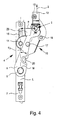
- the fitting 1 is formed such that the pivot angle ⁇ between the bearing strip 7 and its longitudinal axis L and the diegeltragarm 8 and its longitudinal axis M when swinging the wing 2 over 90 ° to a wing angle of at least 135 ° remains unchanged or increases.
- the swivel angle ⁇ can in principle also decrease again.
- the pivot angle ⁇ corresponds to the distance a of the pivot axis of the wing pivot bearing 6, so that the distance a when pivoting the wing over 90 ° out to a wing angle of at least 135 ° either increased or unchanged.
- the Ausstell Tavern worn 10 is formed such that the ratio ⁇ 1 / ⁇ 2 of the pivot angle ⁇ 1 when swinging the wing 2 from 0 ° to 90 ° to the pivot angle ⁇ 2 when swinging the wing 2 from 91 ° to 180th ° from 2 to 4 to 0.5 to 1.5, preferably from 2.5 to 3.5 to 0.75 to 1.25 and in particular at least substantially 3 to 1. It is understood that in principle every single ratio ⁇ 1 / ⁇ 2 within the specified limits is possible, so for example, a ratio ⁇ 1 / ⁇ 2 of 4 to 0.5 or from 2 to 1.5.
- the fitting 1 and the dispensing device 10 is formed such that a pivoting of the wing 2 relative to the bearing belt 7 to 180 ° is possible.
- the swinging to 180 ° is considered to be the end position very favorable.
- the Ausstellêtêt the sheep pain 10 has a multi-joint with a connected to the bearing strip 7 control lever and an angular, connected to a diegelecklagertagens consortium 12 connecting plate 13, wherein the connecting plate 13 and the control lever 11 are hinged together.
- the control lever 11 is displaceably mounted, on the one hand, on the bearing band 7 via a joint 14 and, moreover, in a link 15 via a sliding block 16 and, on the other hand, is articulated on the wing support arm 8 via a joint 17.
- the pogelecklagertagenssian 12 via a joint 19 a, the pivot axis coincides with the pivot axis of the wing pivot bearing 6 and which is ultimately part of the wing pivot bearing 6, connected to the copetragarm 8.
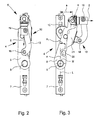
- the diegeltragarm 8 is an edge-side recess 20 for receiving the joint 18 between the control lever 11 and the connecting plate 13 is provided in the closed sash position, as in Fig. 2 is shown.
- the recess 20 preferably has such a depth that the connecting plate 13 in the pivoted state does not or only slightly beyond the outer dimensions of the bearing strip 7.
- the diegeltragarm 8 has a top-side receiving portion 21 of reduced thickness for receiving the connecting plate 13 in the closed sash position.
- the optimum pivot angle ⁇ or distance a of the wing pivot bearing 6 to the frame can be determined when the wing is in a wing angle of 135 ° and the distance of the flashover 22 to the frame is just so that the flashover is not on the frame strikes.
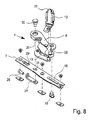
- the diegelecklager 5 on its base 34 on an end angled web 35, which serves as an assembly aid.
- a predetermined breaking point 36th At the transition of the web 35 to the base body 34 is a predetermined breaking point 36th
- 4 adjusting means for height adjustment, side adjustment and Anyakeingnagna can be provided on the wellgelecklager 5 and / or on the compassionecklager.
- a set screw 25 is provided on the winged corner bearing connection piece 12, which acts on a bearing bush, not shown, in the region of the diegelecklagerENSs Kunststoffs 12.
- the Anyakver ein is made by means of a screw 26 which shifts the bearing bush, not shown, forward or backward.
- a plate 27 is provided, which can be adjusted via an adjusting screw 28.
- the plate 27 itself is mounted in the bearing collar 7.
- In the plate 27 is an angle plate, one of whose angled end protrudes through a corresponding opening 29 in the bearing collar 7.
- a hinge part 30 of the joint 9 is mounted in a slot 31.
- the winged deck bearing 5 is attached to the end stop of the web 35 to the profile of the wing.
- a C-groove is provided for the wellgelecklager 5 in the sash profile, in which the diegelecklager 5 is inserted.
- the base body 34 is fastened with appropriate screws.
- the web 35 is bent from the wing 2 and broken away at the predetermined breaking point. Finally, the web 35 simplifies the correct placement of the winged corner bearing 5.
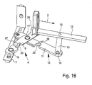
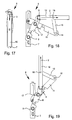
- FIG. 16 to 19 another embodiment of a compassionecklagers 4 according to the invention is shown.
- 20 to 23 show this embodiment of the compassionecklagers 4 in the installed position on a frame 3 and in conjunction with the diegelecklager 5 as a fitting 1 in conjunction with a wing. 2
- the embodiment corresponds to the Fig. 16 to 19 the previously described embodiment, so that in the matching components to avoid repetition of the above References.
- An essential difference is that in the embodiment according to the Fig. 16 ff.
- the connecting strap 13 is designed as an elongated, straight arm or lever.
- the connecting plate 13 in the embodiment described above is angular with a longer and a shorter leg.
- the 180 ° wing position can be achieved both with an angle-shaped or L-shaped connecting lug and with an elongated, straight connecting lug.
- the region of the control lever 11 and the connecting plate 13 about the hinge 18 slightly more into the room from inside and protrudes, for example, beyond the dimensions of the wing 2 addition, as is apparent from Fig. 22.
- FIG. 1 A comparison in particular of Fig. 1 and 16 shows that the control lever 1 in the embodiment according to Fig. 1 is significantly shorter than the control lever 11 in the embodiment according to Fig. 16 ,
- the two embodiments have an important commonality with respect to the distances between the joint axes of the multi-joint.
- the sum of the distance between the axes of rotation of the joints 17 and 18 of the control lever 11 with the rempligeltragarm 8 and the connecting plate 13 and the distance between the axes of rotation of the joints 18 and 19 of the connecting plate 13 with the control lever 11 and the diegelecklagertagens committee 12 is greater than the sum the distance between the axis of rotation of the joint 17 of the Lagertragarms 8 with the control lever 11 and the wing pivot bearing 6 and the distance between the axes of rotation of the wing pivot bearing 6 and the joint 19 of the wing corner bearing connector 12 with the connecting plate 13th
- a projection 39 is provided which serves together with another, not shown, projection for contact pressure amplification.
Abstract
Description
Die Erfindung betrifft einen Beschlag zur verdeckten Anordnung im Falz zwischen einem Flügel und einem Rahmen eines Fensters, einer Tür oder dergleichen, mit einem rahmenseitig zu befestigenden Lagerband eines Rahmenecklagers, einem flügelseitig zu befestigenden Flügelecklager und einem Flügelschwenklager, wobei am Lagerband ein Flügeltragarm gelenkig gelagert ist, und wobei eine mit dem Lagerband und dem Flügeltragarm gekoppelte Ausstelleinrichtung vorgesehen ist, mittels der das Flügelschwenklager beim Aufschwenken des Flügels relativ zum Lagerband ausgeschwenkt wird.The invention relates to a fitting for concealed arrangement in the fold between a wing and a frame of a window, a door or the like, with a frame side to be fastened bearing strip of a Rahmenecklagers, a wing side to be attached Flügelecklager and a wing pivot bearing, wherein a Flügeltragarm is articulated on the bearing strip , And wherein a coupled to the bearing strip and the Flügeltragarm Ausstelleinrichtung is provided by means of which the wing pivot bearing is pivoted when pivoting the wing relative to the bearing strip.
Verdeckt angeordnete Beschläge der eingangs genannten Art, die auch als verdeckt liegende Beschläge bezeichnet werden, sind aus der Praxis bereits seit langem bekannt. Grundsätzlich wird zwischen verdeckt angeordneten Beschlägen und außenseitig sichtbaren Beschlägen unterschieden. Außenseitig sichtbare Beschläge haben den Vorteil, dass es aufgrund der Anordnung der Beschläge auf dem Rahmen grundsätzlich möglich ist, dass der Flügel bis zu 180° aufgeschwenkt wird. Der Nachteil derartiger Beschläge liegt in dem äußerlichästhetisch wenig ansprechenden Design, das sich durch die außenliegende Anordnung der Beschläge ergibt.Concealed fittings of the type mentioned, which are also referred to as concealed fittings, have long been known in practice. Basically, a distinction is made between concealed fittings and externally visible fittings. Exterior visible fittings have the advantage that it is basically possible due to the arrangement of the fittings on the frame, that the wing is swung up to 180 °. The disadvantage of such fittings lies in the aesthetically aesthetically unappealing design that results from the external arrangement of the fittings.
Der vorgenannte Nachteil tritt bei verdeckt angeordneten Beschlägen nicht auf, da derartige Beschläge im geschlossenen Zustand des Flügels äußerlich nicht sichtbar sind, da sie im Falz zwischen dem Flügel und dem Rahmen angeordnet sind.The aforementioned disadvantage does not occur in concealed fittings, since such fittings are outwardly invisible in the closed state of the wing, as they are located in the fold between the wing and the frame.
Die vorliegende Erfindung ist auf solche verdeckt liegenden Beschläge gerichtet, bei denen das Flügelschwenklager beim Aufschwenken des Flügels herausgestellt wird, das heißt vom Rahmen weggeschwenkt wird. Diese Ausstell- oder Ausschwenkbewegung ist in der Regel erforderlich, um ein Aufschwenken des Flügels gegenüber dem Rahmen überhaupt zu ermöglichen.The present invention is directed to such concealed fittings in which the wing pivot bearing is exposed during pivoting of the wing, that is, pivoted away from the frame. This raising or Ausschwenkbewegung is usually required to allow pivoting of the wing relative to the frame at all.
Von Nachteil bei dem bekannten, verdeckt angeordneten Schwenkbelag ist, dass der maximale Aufschwenkwinkel des Flügels gegenüber dem Rahmen in der Regel bei 90° und in Ausnahmefällen bei 110° liegt. Bei den aus der Praxis bekannten Lösungen ist aufgrund der gegebenen Mechanik der Beschläge und insbesondere der Ausstellsteuereinrichtung damit nur ein sehr begrenztes Aufschwenken des Flügels möglich.A disadvantage of the known, concealed pivoting surface is that the maximum Aufschwenkwinkel the wing relative to the frame is usually at 90 ° and in exceptional cases at 110 °. In the solutions known from practice is due to the given mechanics of the fittings and in particular the Ausstellsteuereinrichtung so that only a very limited swinging of the wing possible.
Aufgabe der vorliegenden Erfindung ist es nun, einen Beschlag der eingangs genannten Art zur Verfügung zu stellen, mit dem es möglich ist, den Flügel gegenüber dem Rahmen mehr als 90° und vorzugsweise bis zu 180° aufzuschwenken.Object of the present invention is therefore to provide a fitting of the type mentioned, with which it is possible to swing the wing relative to the frame more than 90 ° and preferably up to 180 °.
Zur Lösung der vorgenannten Aufgabe ist bei einem Beschlag der eingangs genannten Art erfindungsgemäß vorgesehen, dass der Beschlag und insbesondere die Ausstellsteuereinrichtung derart ausgebildet ist, dass der Schwenkwinkel zwischen dem Lagerband und dem Flügeltragarm beim Aufschwenken des Flügels über 90° hinaus zumindest bis 135° unverändert bleibt oder sich vergrößert. Bei der Erfindung ist es also mit anderen Worten so, dass sich der Abstand des Flügelschwenklagers zum Rahmen bzw. zum Lagerband beim Aufschwenken des Flügels über 90° hinaus zumindest bis 135° entweder vergrößert oder aber unverändert bleibt.To achieve the above object is inventively provided in a fitting of the type mentioned that the fitting and in particular the Ausstellsteuereinrichtung is designed such that the pivot angle between the bearing strip and the Flügeltragarm when swinging the wing over 90 ° addition remains unchanged at least to 135 ° or enlarged. In other words, in the case of the invention, in other words, the distance between the wing pivot bearing and the frame or the bearing strip when pivoting the wing beyond 90 ° is either increased to at least 135 ° or remains unchanged.
Die Erfindung sieht demnach zunächst einmal vor, dass der erfindungsgemäße Beschlag ein Aufschwenken des Flügels zumindest bis 135° ermöglicht. Dabei ist es so, dass das Flügelschwenklager bei einem Aufschwenken des Flügels um 90° um einen bestimmten Betrag vom Rahmen abgestellt ist. Wird der Flügel dann beispielsweise von 90° auf 110° weiter aufgeschwenkt, bleibt der Abstand des Schwenklagers zum Lagerband bzw. zum Rahmen gleich oder aber er vergrößert sich. Dieser Zustand tritt jedenfalls so lange auf, bis der Flügel auf 135° aufgeschwenkt ist. Dieser Winkel beim Aufschwenken des Flügels wird als kritischer Winkel bezeichnet, da der Abstand des Überschlags des Flügels zum Rahmen hierbei am geringsten ist. Wird der Flügel anschließend weiter, also über 135° aufgeschwenkt, vergrößert sich der lichte Abstand des Überschlags zum Rahmen wieder. Von daher ist es nach Überschreiten des Winkels von 135° grundsätzlich möglich, dass der Schwenkwinkel zwischen dem Lagerband und dem Flügeltragarm bzw. der Abstand des Flügelschwenklagers zum Rahmen sich wieder verringert. Natürlich ist es grundsätzlich auch möglich, dass sich dieser Schwenkwinkel nach Überschreiten der 135°-Flügelstellung unverändert bleibt oder aber weiter vergrößert.Accordingly, the invention initially provides that the fitting according to the invention makes it possible to pivot the wing up to at least 135 °. It is the case that the wing pivot bearing is turned off by a certain amount from the frame when the wing is pivoted 90 °. If the wing is then swung further, for example, from 90 ° to 110 °, the distance between the pivot bearing and the bearing strip or frame remains the same or it increases. This condition occurs in any case until the wing is pivoted to 135 °. This angle when swinging the wing is referred to as a critical angle, since the distance of the rollover of the wing to the frame here is the lowest. If the wing then continues, so swung over 135 °, the clear distance of the rollover to the frame increases again. Therefore, it is basically possible after exceeding the angle of 135 °, that the pivot angle between the bearing strip and the Flügeltragarm or the distance of the wing pivot bearing to the frame is reduced again. Of course, it is also possible in principle that this pivot angle remains unchanged after exceeding the 135 ° wing position or further increased.
Letztlich sollte, um optimale Winkelverhältnisse und geringe Spaltgrößen zu haben, der maximale Schwenkwinkel bzw. der Abstand des Flügelschwenklagers zum Rahmen bei einer Aufschwenkstellung des Flügels von 135° so gewählt werden, dass ein minimaler Abstand zwischen dem Überschlag des Flügels und dem Rahmen entsteht.Ultimately, in order to have optimal angular ratios and small gap sizes, the maximum swing angle or the distance of the wing pivot bearing to the frame at a swivel position of the wing of 135 ° be chosen so that a minimum distance between the flap of the wing and the frame is formed.
Bei der Erfindung ist im Ergebnis erkannt worden, dass ein Aufschwenken des Flügels über einen bestimmten Wert, in der Regel 90°, hinaus beim Stand der Technik häufig deshalb unmöglich ist, da, selbst wenn man die beim Stand der Technik in der Regel realisierten Kulissenführungen erweitern bzw. verlängern würde, das Flügelschwenklager bei Überschreiten der 90°-Stellung sich wieder in Richtung des Lagerbandes bewegt, der Abstand zum Rahmen sich also verringert. Diese Verringerung des Abstandes des Flügelschwenklagers zum Lagerband und damit zum Rahmen verhindert jedoch ein weiteres Aufschlagen des Flügels über 90° oder maximal 110° hinaus. Da bei der Erfindung der Abstand des Flügelschwenklagers bei einem Schwenken des Flügels über 90° hinaus zumindest bis 135° jedoch unverändert bleibt oder sich vergrößert, tritt die vorgenannte Problematik nicht auf.In the invention has been recognized in the result that a swinging of the wing above a certain value, usually 90 °, in the prior art often therefore impossible because even if one of the prior art usually implemented slotted guides expand or extend the wing pivot bearing when the 90 ° position is exceeded again moves in the direction of the bearing strip, the distance to the frame is thus reduced. However, this reduction of the distance of the wing pivot bearing to the bearing strip and thus the frame prevents further impact of the wing over 90 ° or 110 ° maximum addition. However, since in the invention, the distance of the wing pivot bearing at a pivoting of the wing over 90 ° beyond at least up to 135 ° remains unchanged or increases, the aforementioned problem does not occur.
Im Zusammenhang mit der erfindungsgemäßen Ausgestaltung des Beschlages ist festgestellt worden, dass es ausgesprochen zweckmäßig ist, wenn das Flügelschwenklager zu Beginn der Aufschwenkbewegung des Flügels stärker nach außen schwenkt, als dies beim weiteren Aufschwenken und insbesondere beim Schwenken in die maximale Endstellung hin der Fall ist. Konstruktiv ist in diesem Zusammenhang vorgesehen, dass das Verhältnis des Schwenkwinkels beim Schwenken des Flügels von 0° bis 90° zum Schwenkwinkel beim Schwenken des Flügels von 91° bis 180° von 2 bis 4 zu 0,5 bis 1,5, vorzugsweise von 2,5 bis 3,5 zu 0,75 bis 1,25 und insbesondere zumindest im Wesentlichen 3 zu 1 beträgt. Innerhalb der Bereichsgrenzen ist grundsätzlich jeder einzelne Verhältniswert möglich. In Ausnahmefällen ist es sogar möglich, dass, wie zuvor bereits erwähnt worden ist, beispielsweise nach Erreichen der 90°-Stellung überhaupt kein weiteres Ausstellen des Flügelschwenklagers erfolgt.In connection with the inventive design of the fitting has been found that it is extremely useful when the wing pivot bearing pivots at the beginning of the pivoting movement of the wing more outward than this is the case during further pivoting and in particular when pivoting in the maximum end position. Structurally, it is provided in this context that the ratio of the pivoting angle during pivoting of the wing from 0 ° to 90 ° to the pivoting angle during pivoting of the wing from 91 ° to 180 ° from 2 to 4 to 0.5 to 1.5, preferably from 2 , 5 to 3.5 to 0.75 to 1.25 and in particular at least substantially 3 to 1. Within the range limits, each individual ratio value is possible in principle. In exceptional cases, it is even possible that, as previously mentioned, for example, after reaching the 90 ° position, no further exhibiting the wing pivot bearing takes place.
Bei einer besonders bevorzugten Ausführungsform der Erfindung ist der Beschlag und insbesondere die Ausstellsteuereinrichtung derart ausgebildet, dass ein Aufschwenken des Flügels relativ zum Lagerband bis 160°, vorzugsweise bis 180° möglich ist. Dabei versteht es sich, dass ein Aufschwenken bis zu jedem Einzelwert, der zwischen 110° und 180° liegt, also 111°, 112°, 113° ... 178°, 179° und 180°, als maximaler Aufschwenkwert möglich ist, auch wenn der Einzelwert nicht konkret angegeben ist. Hinzuweisen ist darauf, dass es bei der Erfindung sogar grundsätzlich möglich ist, ein Aufschwenken über 180° hinaus, vorzunehmen, wenngleich dies üblicherweise nicht unbedingt zweckmäßig ist. Letztlich ergeben sich bei der Erfindung damit die gleichen Vorteile wie bei außenliegenden Beschlägen, also ein maximales Aufschwenken des Flügels bis zu 180°, wobei sich beim maximalen Aufschwenken gleichzeitig der positive Effekt ergibt, dass auch der Falz des Flügels aus dem Öffnungsbereich des Rahmens herausgeschwenkt ist, also eine vollständige Durchsicht durch die Rahmenöffnung möglich ist.In a particularly preferred embodiment of the invention, the fitting and in particular the Ausstellsteuereinrichtung is designed such that a pivoting of the wing relative to the bearing belt to 160 °, preferably up to 180 ° is possible. It is understood that a swing up to each individual value, which is between 110 ° and 180 °, ie 111 °, 112 °, 113 ° ... 178 °, 179 ° and 180 °, as a maximum Aufschwenkwert is possible, too if the individual value is not specified concretely. It should be pointed out that it is at the Invention is even possible in principle, a swinging over 180 ° addition to make, although this is usually not necessarily appropriate. Ultimately arise in the invention so that the same advantages as with external fittings, so a maximum swinging of the wing up to 180 °, with the maximum swinging results simultaneously the positive effect that the fold of the wing is pivoted out of the opening portion of the frame , So a complete view through the frame opening is possible.
Bei einer besonders bevorzugten Ausgestaltung, die sowohl für sich als auch in Kombination mit der vorgenannten erfindungsgemäßen Ausgestaltung möglich ist, ist vorgesehen, dass die Ausstellsteuereinrichtung ein Mehrgelenk mit einem mit dem Lagerband verbundenen Steuerhebel und einer insbesondere winkelförmigen Verbindungslasche aufweist, wobei die Verbindungslasche und der Steuerhebel gelenkig miteinander verbunden sind. Durch das vorgenannte Mehrgelenk kann eine Zwangssteuerung realisiert werden, die einerseits eine sichere Ausstellbewegung des Flügelschwenklagers gewährleistet und die es im Übrigen ermöglicht, den Flügel gegenüber dem Rahmen bzw. dem Lagerband bis zu 180° aufzuschwenken.In a particularly preferred embodiment, which is possible both for itself and in combination with the aforementioned embodiment according to the invention, it is provided that the Ausstellsteuereinrichtung has a multi-joint with a bearing lever connected to the control lever and a particular angle-shaped connecting plate, wherein the connecting link and the control lever are hinged together. By the aforementioned multi-joint positive control can be realized, on the one hand ensures a safe deployment movement of the wing pivot bearing and which, moreover, allows the wing relative to the frame or the bearing strip aufzuschwenken up to 180 °.
In vorteilhafter Weise kann eine derartige Zwangssteuerung dann dadurch realisiert sein, dass die Verbindungslasche an einem relativ zum Flügel ortsfesten Gelenk angelenkt ist. Dadurch wird es ermöglicht, die Bewegung des Flügels über die Verbindungslasche auf den Steuerhebel zu übertragen und so die Zwangssteuerung zu verwirklichen. Dabei ist es in vorteilhafter Weise möglich, die Verbindungslasche mit einem Flügelecklagerverbindungsstück gelenkig zu verbinden. Vorzugsweise ist diese gelenkige Verbindung das relativ zum Flügel ortsfeste Gelenk der Verbindungslasche. Das Flügelecklagerverbindungsstück dient insbesondere der Verbindung des Flügelschwenklagers mit dem Flügelecklager. Es erfüllt aber auch die Funktion, bei montiertem Flügel ein relativ zum Flügel ortsfestes Gelenk zur gelenkigen Verbindung des Flügels mit der Verbindungslasche bereit zu stellen. Dieses Gelenk ist bevorzugt vom Flügelschwenklager beabstandet, um die Schwenkbewegung des Flügels auf die Verbindungslasche zu übertragen.Advantageously, such a positive control can then be realized in that the connecting plate is articulated to a fixed relative to the wing hinge. This makes it possible to transmit the movement of the wing on the connecting link on the control lever and thus to realize the positive control. It is advantageously possible to connect the connecting plate articulated with a Flügelecklagerverbindungsstück. Preferably, this articulated connection is the relative to the wing fixed joint of the connecting plate. The Flügelecklagerverbindungsstück serves in particular the connection of the wing pivot bearing with the wingedeck bearing. However, it also fulfills the function of providing a wing fixed to the wing relative to the wing for the articulated connection of the wing with the connecting lug when the wing is mounted. This joint is preferably spaced from the wing pivot bearing to transmit the pivotal movement of the wing to the connecting tab.
Konstruktiv ist bei der erfindungsgemäßen Mehrgelenk-Lösung bevorzugt vorgesehen, dass der Steuerhebel einerseits an dem Lagerband gelenkig und in einer Kulisse über einen Kulissenstein verschieblich gelagert und andererseits am Flügeltragarm gelenkig gelagert ist. Grundsätzlich könnte auch der Flügeltragarm über ein solches translatorisches Gelenk gelagert sein.Structurally is preferably provided in the multi-joint solution according to the invention that the control lever articulated on the one hand on the bearing tape and slidably mounted in a gate on a sliding block and on the other hand is articulated on Flügeltragarm. In principle, the Flügeltragarm could be stored on such a translational joint.
Das translatorische Gelenk kann dabei auch auf eine andere Weise als durch eine Kulissenführung realisiert sein. Prinzipiell ist jede körperliche Ausgestaltung möglich, solange der Flügeltragarm und der Steuerhebel derart am Lagerband gelenkig gelagert sind, dass die Drehachsen der gelenkigen Lagerung relativ zueinander verschieblich sind.The translational joint can also be realized in a different way than by a slotted guide. In principle, any physical embodiment is possible, as long as the Flügeltragarm and the control lever are so articulated on the bearing strip, that the axes of rotation of the articulated mounting are displaceable relative to each other.
Durch die vorgenannte Lagerung des Steuerhebels am Lagerband und am Flügeltragarm sowie die gelenkige Verbindung des Flügelecklagerverbindungsstück mit der Verbindungslasche ergibt sich letztlich die Ausstellbewegung des Flügelschwenklagers beim Aufschwenken des Flügels, wobei gleichzeitig durch die gelenkig gelagerte Verbindungslasche das maximale Aufschwenken des Flügelecklagers und damit des Flügels gewährleistet ist. In diesem Zusammenhang versteht es sich, dass die Kulisse bzw. die Kulissenführung eine solche Länge hat, dass eine maximale Bewegung des Steuerhebels in Verbindung mit der Bewegung der Verbindungslasche zum Aufschwenken des Flügels bis zu 180° möglich ist.Due to the aforementioned storage of the control lever on the bearing strip and the Flügeltragarm and the articulated connection of the Flügelecklagerverbindungsstück with the connecting plate ultimately results in the deployment movement of the wing pivot bearing when swinging the wing, while the maximum pivoting of the Flügelecklagers and thus the wing is guaranteed by the articulated connection plate , In this context, it is understood that the link or the slide guide has a length such that a maximum movement of the control lever in conjunction with the movement of the connecting plate for pivoting the wing up to 180 ° is possible.
Um das Spaltmaß zwischen dem Flügel und dem Rahmen beim Aufschwenken möglichst klein zu halten und einen Einklemmschutz zu erreichen, ist die Drehachse des Kulissensteins in jedem Verschiebezustand innerhalb der Kulisse vor dem Gelenk des Flügeltragarms und des Steuerhebels, so dass der Totpunkt dieses Gelenks zu keinem Zeitpunkt überschritten wird.In order to keep the gap between the wing and the frame when swinging as small as possible and to achieve an anti-trap, the axis of rotation of the sliding block in each sliding state within the backdrop before the joint of Flügeltragarms and the control lever, so that the dead center of this joint at any time is exceeded.
Um den erfindungsgemäßen Beschlag möglichst kleinbauend, aber dennoch hinreichend stabil auszugestalten, ist im Flügeltragarm eine randseitige Ausnehmung zur Aufnahme des Gelenks zwischen dem Steuerhebel und der Verbindungslasche in der geschlossenen Flügelstellung vorgesehen. Hierdurch ist es selbst bei einer winkelförmigen Ausbildung der Verbindungslasche möglich, diese vollständig oder zumindest fast vollständig im Bereich oberhalb des Lagerbandes anzuordnen.In order to design the fitting according to the invention as small as possible but nevertheless sufficiently stable, an edge-side recess for receiving the joint between the control lever and the connecting plate in the closed leaf position is provided in the wing support arm. This makes it possible even with an angular configuration of the connecting plate to arrange them completely or at least almost completely in the area above the bearing strip.
Im Übrigen ist es ebenfalls von Vorteil, dass der Flügeltragarm einen oberseitigen Aufnahmebereich verminderter Dicke zur Aufnahme der Verbindungslasche in der geschlossenen Flügelstellung aufweist. Letztlich kann dabei die Tiefe des oberseitigen Öffnungsbereichs zumindest im Wesentlichen der Dicke der Verbindungslasche entsprechen, so dass die Verbindungslasche in der geschlossenen Flügelstellung zumindest im Wesentlichen im Aufnahmebereich aufgenommen ist. Die Verbindungslasche steht damit nicht oder allenfalls geringfügig über den Flügeltragarm über, was zu einem relativ flachen Beschlag führt. Gleichzeitig ist durch diese Ausgestaltung gewährleistet, dass der Flügeltragarm noch eine hinreichende Festigkeit zur Aufnahme der sich durch den Flügel selbst bzw. dessen Handhabung resultierenden Kräfte hat.Incidentally, it is also advantageous that the Flügeltragarm has a top-side receiving portion of reduced thickness for receiving the connecting plate in the closed sash position. In the end, the depth of the upper-side opening area can at least essentially be the thickness of the connecting strap correspond, so that the connecting plate is received in the closed wing position, at least substantially in the receiving area. The connecting plate is thus not or at most slightly over the Flügeltragarm over, resulting in a relatively flat fitting. At the same time it is ensured by this design that the Flügeltragarm still has sufficient strength to accommodate the resulting itself by the wing itself or its handling forces.
Besonders bevorzugt ist es im Übrigen, dass am Flügeltragarm, am Lagerband und/oder am Steuerhebel Ausnehmungen zur Bildung eines Freiraums zur Aufnahme eines randseitigen Überschlags des Flügels vorgesehen sind. Letztlich ist sowohl der Steuerhebel, als auch der Flügeltragarm in der maximalen Aufschwenkstellung des Flügels von 180° so eingeschnitten bzw. ausgenommen, dass der Überschlag des Flügels aufgenommen werden kann. Bedarfsweise ist es in diesem Zusammenhang auch möglich, eine entsprechende Ausnehmung an dem Lagerband vorzunehmen. Die vorgenannten Ausnehmungen am Flügeltragarm und/oder Steuerhebel und/oder Lagerband stellen letztlich "Materialweglassungen" oder "-wegnahmen" dar, die die Festigkeit der betreffenden Bauteile nicht beeinträchtigen.It is particularly preferred, moreover, that recesses are provided on the wing support arm, on the bearing strip and / or on the control lever to form a free space for receiving a marginal rollover of the wing. Ultimately, both the control lever, as well as the Flügeltragarm in the maximum Aufschwenkstellung the wing of 180 ° cut or excluded so that the flashover of the wing can be accommodated. If necessary, it is also possible in this context to make a corresponding recess on the bearing strip. The aforementioned recesses on Flügeltragarm and / or control lever and / or storage tape ultimately represent "Materialweglassen" or "-wegnahmen", which do not affect the strength of the components concerned.
Um ein einfaches Ein- und Aushängen des Flügels zu gewährleisten, ist bei dem erfindungsgemäßen Beschlag vorgesehen, dass das Flügelecklager lediglich mit dem Flügelecklagerverbindungsstück, das Teil der Baugruppe des Rahmenecklagers ist, zu verbinden ist. Dabei wird das Flügelecklager am Flügel vormontiert, während das Flügelecklagerverbindungsstück am Flügeltragarm und der Verbindungslasche befestigt und mit dem gesamten Rahmenecklager am Rahmen vormontiert wird. Beim Einsetzen des Flügels in den Rahmen wird lediglich das Flügelecklager in das Flügelecklagerverbindungsstück eingesetzt und anschließend fest damit verbunden. Letztlich wird durch die Realisierung des Flügelecklagerverbindungsstückes als Teil des Rahmenecklagers einerseits und des Flügelecklagers andererseits eine Schnittstelle zwischen dem Flügel und dem Rahmen zur Verfügung gestellt, die eine sehr einfache Flügelmontage und -demontage gewährleistet.In order to ensure easy mounting and dismounting of the wing, it is provided in the fitting according to the invention that the winged corner bearing is to be connected only to the winged corner bearing connecting piece, which is part of the assembly of the frame corner bearing. The wing cap bearing is preassembled on the wing, while the Flügelecklagerverbindungsstück attached to Flügeltragarm and the connecting plate and is pre-assembled with the entire Rahmenecklager on the frame. When inserting the wing into the frame, only the winged corner bearing is inserted into the winged corner bearing connector and then firmly connected thereto. Ultimately, an interface between the wing and the frame is provided by the realization of the Flügelecklagerverbindungsstückes as part of the Rahmenecklagers on the one hand and the Flügelecklagers on the other hand, which ensures a very simple wing assembly and disassembly.
Um den Flügel im Rahmen in einfacher Weise justieren zu können, sind am Flügelecklager und/oder am Rahmenecklager Justiermittel zur Höhenverstellung, Seitenverstellung und/oder Andruckverstellung vorgesehen. So kann beispielsweise am unteren Flügelecklagerabschnitt eine Stellschraube zur Höhenverstellung vorgesehen sein, die auf eine Lagerbuchse des Flügelschwenklagers wirkt. In gleicher Weise kann eine Andruckverstellung erfolgen, wenn eine weitere Stellschraube von vom oder hinten auf die Lagerbuchse wirkt und diese bei entsprechender Einstellung verschiebt Auch kann über das Lagerband eine Verstellung, insbesondere eine Seitenverstellung, vorgenommen werden. Hierzu kann am Lagerband ein mit dem Lagerbolzen des Flügeltragarms verbundener, verstellbarer Schieber vorgesehen sein, dessen Verstellung beispielsweise über eine Stellschraube zu einer Verstellung des Lagerbolzens führt.In order to adjust the wing in the frame in a simple manner, adjustment means for height adjustment, side adjustment and / or Andruckverstellung are provided on Flügelecklager and / or on Rahmenecklager. Thus, for example, at the lower Flügelecklagerabschnitt an adjusting screw for height adjustment be provided, which acts on a bearing bush of the wing pivot bearing. In the same way, a Andruckverstellung done when another screw from the rear or on the bearing bush acts and this shifts with appropriate setting Also on the bearing band adjustment, in particular a lateral adjustment can be made. For this purpose, an adjustable slide connected to the bearing pin of the Flügeltragarms can be provided on the bearing strip, the adjustment leads, for example via an adjusting screw to an adjustment of the bearing pin.
Weitere Merkmale, Vorteile und Anwendungsmöglichkeiten der vorliegenden Erfindung ergeben sich aus der nachfolgenden Beschreibung von Ausführungsbeispielen anhand der Zeichnung und der Zeichnung selbst. Dabei bilden alle beschriebenen und/oder bildlich dargestellten Merkmale für sich oder in beliebiger Kombination den Gegenstand der vorliegenden Erfindung, unabhängig von ihrer Zusammenfassung in den Ansprüchen oder deren Rückbeziehung.Other features, advantages and applications of the present invention will become apparent from the following description of exemplary embodiments with reference to the drawing and the drawing itself. In this case, all described and / or illustrated features, alone or in any combination, the subject of the present invention, regardless of their Summary in the claims or their dependency.
Es zeigt
- Fig. 1
- eine perspektivische Ansicht eines erfindungsgemäßen Beschlages,
- Fig. 2
- eine Darstellung eines Rahmeneckbandes des Beschlages in geschlossener Stellung eines Flügels,
- Fig. 3
- eine Darstellung eines Rahmeneckbandes des Beschlages aus
Fig. 2 mit um 90° aufgeschwenktem Flügel, - Fig. 4
- eine Darstellung entsprechend den
Fig. 2 und 3 mit um 180° aufgeschwenktem Flügel, - Fig. 5
- eine Draufsicht auf ein Rahmenecklager des erfindungsgemäßen Beschlages,
- Fig. 6
- eine Seitenansicht des Rahmenecklagers aus
Fig. 5 , - Fig. 7
- eine Unteransicht des Rahmenecklagers aus
Fig. 5 , - Fig. 8
- eine Explosionsdarstellung des Rahmeneckstücks aus
Fig. 5 , - Fig. 9
- eine Draufsicht einer Baugruppe des Rahmeneckstücks,
- Fig. 10
- eine Explosionsdarstellung der Baugruppe aus
Fig. 9 , - Fig. 11
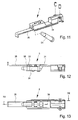
- eine perspektivische Ansicht eines Flügeleckstücks,
- Fig. 12
- eine Seitenansicht des Flügeleckstücks aus
Fig. 11 , - Fig. 13
- eine Unteransicht des Flügeleckstücks auf
Fig. 11 , - Fig. 14
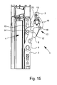
- eine Darstellung eines erfindungsgemäßen Beschlages in Einbaustellung am Rahmen und am Flügel.
- Fig. 15
- eine Darstellung entsprechend
Fig. 14 unter Weglassung des Rahmens, - Fig. 16
- eine perspektivische Ansicht einer anderen Ausführungsform eines Rahmeneckbandes eines erfindungsgemäßen Beschlages,
- Fig. 17
- eine Draufsicht auf das Rahmeneckband aus
Fig. 16 in geschlossener Flügelstellung, - Fig. 18
- eine Draufsicht auf das Rahmenecklager aus
Fig. 17 in 90°Flügelstellung, - Fig. 19
- eine Draufsicht auf das Rahmeneckteil aus
Fig. 17 in 180°Fiügelstellung, - Fig. 20
- eine perspektivische Ansicht des Rahmenecklagers aus
Fig. 16 im an einen Rahmen angesetzten Zustand, - Fig. 21
- eine Draufsicht auf das angesetzte Rahmenecklager aus Fig. 20,
- Fig. 22
- eine perspektivische Ansicht eines Beschlages mit dem Rahmenecklager aus
Fig. 16 mit angedeutetem Flügel und - Fig. 23
- eine Draufsicht auf den Beschlag aus Fig. 22.
- Fig. 1
- a perspective view of a fitting according to the invention,
- Fig. 2
- a representation of a Rahmeneckbandes the fitting in the closed position of a wing,
- Fig. 3
- a representation of a frame corner band of the fitting
Fig. 2 with wing pivoted by 90 °, - Fig. 4
- a representation according to the
FIGS. 2 and 3 with wings pivoted by 180 °, - Fig. 5
- a plan view of a frame corner bearing of the fitting according to the invention,
- Fig. 6
- a side view of the frame corner bearing
Fig. 5 . - Fig. 7
- a bottom view of the frame corner bearing
Fig. 5 . - Fig. 8
- an exploded view of the frame corner piece
Fig. 5 . - Fig. 9
- a plan view of an assembly of Rahmeneckstücks,
- Fig. 10
- an exploded view of the assembly
Fig. 9 . - Fig. 11
- a perspective view of a wing corner piece,
- Fig. 12
- a side view of the wing corner piece
Fig. 11 . - Fig. 13
- a bottom view of the wing corner piece
Fig. 11 . - Fig. 14
- an illustration of a fitting according to the invention in the installed position on the frame and on the wing.
- Fig. 15
- a representation accordingly
Fig. 14 omitting the frame, - Fig. 16
- a perspective view of another embodiment of a frame corner band of a fitting according to the invention,
- Fig. 17
- a plan view of the frame corner band
Fig. 16 in closed wing position, - Fig. 18
- a plan view of the frame corner bearing
Fig. 17 in 90 ° wing position, - Fig. 19
- a plan view of the frame corner part
Fig. 17 in 180 ° wing position, - Fig. 20
- a perspective view of the Rahmenecklagers
Fig. 16 in the condition attached to a frame, - Fig. 21
- a top view of the attached frame corner bearing of FIG. 20,
- Fig. 22
- a perspective view of a fitting with the Rahmenecklager
Fig. 16 with indicated wings and - Fig. 23
- a plan view of the fitting of FIG. 22nd
In
Zur Befestigung des Rahmenecklagers 4 am Rahmen 3 dient ein Lagerband 7. Zur Baugruppe des Rahmenecklagers 4 gehört neben dem Lagerband 7 ein Flügeltragarm 8, der über ein Gelenk 9 mit dem Lagerband 7 schwenkbar verbunden ist. Weiterhin weist das Rahmenecklager 4 eine mit dem Lagerband 7 und dem Flügeltragarm 8 gekoppelte Ausstellsteuereinrichtung 10 auf, mittels der das Flügelschwenklager 6 beim Aufschwenken des Flügels 2 relativ zum Lagerband 7 ausgeschwenkt wird.For mounting the
Vorgesehen ist nun, dass der Beschlag 1 derart ausgebildet ist, dass der Schwenkwinkel α zwischen dem Lagerband 7 bzw. dessen Längsachse L und dem Flügeltragarm 8 bzw. dessen Längsachse M beim Aufschwenken des Flügels 2 über 90° bis zu einem Flügelwinkel von zumindest 135° hinaus unverändert bleibt oder sich vergrößert. Danach kann sich der Schwenkwinkel α grundsätzlich auch wieder verkleinern. Letztlich korrespondiert der Schwenkwinkel α mit dem Abstand a der Schwenkachse des Flügelschwenklagers 6, so dass sich der Abstand a beim Aufschwenken des Flügels über 90° hinaus bis zu einem Flügelwinkel von zumindest 135° entweder vergrößert oder unverändert bleibt. Bei der in den
Letztlich ist es bei dem Beschlag 1 so, dass die Ausstellsteuereinrichtung 10 derart ausgebildet ist, dass das Verhältnis α1/α2 des Schwenkwinkels α1 beim Schwenken des Flügels 2 von 0° bis 90° zum Schwenkwinkel α2 beim Schwenken des Flügels 2 von 91° bis 180° von 2 bis 4 zu 0,5 bis 1,5, vorzugsweise von 2,5 bis 3,5 zu 0,75 bis 1,25 und insbesondere zumindest im Wesentlichen 3 zu 1 beträgt. Dabei versteht es sich, dass grundsätzlich jedes einzelne Verhältnis α1/α2 innerhalb der angegebenen Grenzen möglich ist, also beispielsweise auch ein Verhältnis α1/α2 von 4 zu 0,5 oder von 2 zu 1,5.Finally, it is in the
Im Übrigen ist, wie dies aus
Bei dem erfindungsgemäßen Beschlag 1 weist die Ausstellsteuereinrichtung 10 ein Mehrgelenk mit einem mit dem Lagerband 7 verbundenen Steuerhebel und einer winkelförmigen, mit einem Flügelecklagerverbindungsstück 12 verbundenen Verbindungslasche 13 auf, wobei die Verbindungslasche 13 und der Steuerhebel 11 gelenkig miteinander verbunden sind. Dabei ist der Steuerhebel 11 einerseits an dem Lagerband 7 über ein Gelenk 14 und im Übrigen in einer Kulisse 15 über einen Kulissenstein 16 verschieblich gelagert und andererseits am Flügeltragarm 8 über ein Gelenk 17 gelenkig gelagert. Im Übrigen befindet sich ein Gelenk 18 zwischen dem Steuerhebel 11 und der Verbindungslasche 13, während ein weiteres Gelenk 19 zwischen der Verbindungslasche 13 und dem Flügelecklagerverbindungsstück 12 vorgesehen ist. Im Übrigen ist das Flügelecklagerverbindungsstück 12 über ein Gelenk 19a, dessen Schwenkachse mit der Schwenkachse des Flügelschwenklagers 6 übereinstimmt und das letztlich Teil des Flügelschwenklagers 6 ist, mit dem Flügeltragarm 8 verbunden.In the fitting 1 according to the invention, the
Hinzuweisen ist darauf, dass es grundsätzlich auch möglich ist, das Gelenk 14 nur als Drehgelenk (wie das zuvor beschriebene Gelenk 9) und das Gelenk 9 (wie das zuvor beschriebene Gelenk 14) als translatorisches Gelenk auszuführen. Letztlich ergibt sich hierdurch funktional kein Unterschied.It should be pointed out that in principle it is also possible to design the joint 14 only as a swivel joint (like the previously described joint 9) and the joint 9 (as the previously described joint 14) as a translational joint. Ultimately, this results in no functional difference.
Wie sich im Übrigen insbesondere aus einem Vergleich der
Wie sich weiterhin aus einem Vergleich der
Wie sich aus den
Wie sich beispielsweise aus
Im Übrigen weist das Flügelecklager 5 an seinem Grundkörper 34 einen endseitig abgewinkelten Steg 35 auf, der als Montagehilfe dient. Am Übergang des Stegs 35 zum Grundkörper 34 befindet sich eine Sollbruchstelle 36.Incidentally, the
Im Übrigen können am Flügelecklager 5 und/oder am Rahmenecklager 4 Justiermittel zur Höhenverstellung, Seitenverstellung und Andruckeinstellung vorgesehen sein. Konkret ist am Flügelecklagerverbindungsstück 12 eine Stellschraube 25 vorgesehen, die auf eine nicht dargestellte Lagerbuchse im Bereich des Flügelecklagerverbindungsstücks 12 wirkt. Weiterhin wird die Andruckverstellung mittels einer Stellschraube 26 vorgenommen, die die nicht dargestellte Lagerbuchse nach vorne oder hinten verschiebt.Incidentally, 4 adjusting means for height adjustment, side adjustment and Andruckeinstellung can be provided on the
Zur Seitenverstellung ist eine Platte 27 vorgesehen, die über eine Stellschraube 28 verstellt werden kann. Die Platte 27 selbst ist im Lagerbund 7 gelagert. Bei der Platte 27 handelt es sich um eine Winkelplatte, deren eines abgewinkeltes Ende durch eine entsprechende Öffnung 29 im Lagerbund 7 hindurchragt. Am dem abgewinkelten Ende gegenüberliegenden Ende der Platte 27 ist ein Gelenkteil 30 des Gelenks 9 in einem Langloch 31 gelagert. Durch Verstellung der Stellschraube 28 lässt sich letztlich das Gelenk 9 innerhalb des Langlochs 31 verstellen.For lateral adjustment, a
Die Herstellung eines Beschlages 1 bzw. der zugehörigen Einzelteile erfolgt derart, dass zunächst die Baugruppe des Flügeltragarms 8, des Steuerhebels 11 und der Verbindungslasche 13 zusammengestellt wird. An den jeweiligen Gelenken erfolgt dabei eine Vernietung. Konkret ist dies in den
Sodann kann diese Baugruppe mit dem Lagerband 7 verbunden werden. Anschließend wird dann auch das Flügelecklagerverbindungsstück 12 mit dem Flügeltragarm 8 und der Verbindungslasche 13 verbunden. Dies ergibt sich letztlich insbesondere aus
Zur Montage wird das Rahmenecklager 4 am Rahmen 3 und das Flügelecklager 5 am Flügel 2 vormontiert. Zur Montage des Flügelecklagers 5 am Flügel 2 wird das Flügelecklager 5 bis zum endseitigen Anschlag des Steges 35 an das Profil des Flügels angesetzt. In der Regel ist für das Flügelecklager 5 im Flügelprofil eine C-Nut vorgesehen, in die das Flügelecklager 5 eingeschoben wird. Anschließend wird der Grundkörper 34 mit entsprechenden Schrauben befestigt. Sodann wird der Steg 35 vom Flügel 2 abgebogen und an der Sollbruchstelle weggebrochen. Letztlich vereinfacht der Steg 35 das korrekte Ansetzen des Flügelecklagers 5.For mounting the frame corner bearing 4 on the
Um ein einfaches Ein- und Aushängen des Flügels zu gewährleisten, gibt es letztlich nur eine Schnitt- bzw. Verbindungsstelle zwischen den beiden Baugruppen über die Schraube 24, die in das Flügelecklagerverbindungsstück 12 eingeschraubt wird.In order to ensure easy insertion and removal of the wing, there is ultimately only one interface between the two assemblies via the
Durch einen vom Flügelecklagerverbindungsstück 12 abstehenden Vorsprung 32, der in eine entsprechende Aufnahme 33 am Flügelecklager 5 eintaucht, ergibt sich ein Formschluss der beiden Baugruppen in Drehrichtung des Flügelschwenklagers 6, während sich durch die Schraubverbindung über die Schraube 24 eine kraftschlüssige Verbindung ergibt.By protruding from the
Die Funktion des Beschlages 1 lässt sich am deutlichsten aus den
In den
In technischer Hinsicht entspricht die Ausführungsform gemäß den
Darüber hinaus bestehen hinsichtlich der konstruktiven Ausgestaltung des Flügeltragarms 8 und des Steuerhebels 11 Unterschiede dahingehend, dass bei der Ausführungsform gemäß den
Ein Vergleich insbesondere der
In den Figuren, insbesondere in den
Dies hat zur Folge, dass die Länge der Strecke, die vom Gelenk 17 über das Flügelschwenklager 6 zum Gelenk 19 führt, länger ist als die Strecke, die vom Gelenk 17 über das Gelenk 18 zum Gelenk 19 führt. Dieses Längenverhältnis trägt wesentlich dazu bei, dass hohe Öffnungswinkel des Flügels realisiert werden können. Besonders deutlich wird dies beim Vergleich der
Im Übrigen ist bei der Ausführungsform gemäß den
Im Übrigen ist darauf hinzuweisen, dass es grundsätzlich möglich ist, einen Anschlag vorzusehen, der ein Aufschwenken des Flügels über die 180°Flügelstellung hinaus verhindert. Ein solcher Anschlag kann, muss jedoch nicht vorgesehen sein.Incidentally, it should be noted that it is basically possible to provide a stop which prevents the wing from swinging over the 180 ° sash position. Such a stop may, but need not be, provided.
- 11
- Beschlagfitting
- 22
- Flügelwing
- 33
- Rahmenframe
- 44
- RahmenecklagerRahmenecklager
- 55
- FlügelecklagerWing corner bearing
- 66
- FlügelschwenklagerWing pivot bearings
- 77
- Lagerbandbearing strip
- 88th
- FlügeltragarmFlügeltragarm
- 99
- Gelenkjoint
- 1010
- Ausstelleinrichtungraising means
- 1111
- Steuerhebelcontrol lever
- 1212
- FlügelecklagerverbindungsstückWing corner bearing fitting
- 1313
- Verbindungslascheconnecting strap
- 1414
- Gelenkjoint
- 1515
- Kulissescenery
- 1616
- Kulissensteinsliding block
- 1717
- Gelenkjoint
- 1818
- Gelenkjoint
- 1919
- Gelenkjoint
- 19a19a
- Gelenkjoint
- 2020
- Ausnehmungrecess
- 2121
- Aufnahmebereichreception area
- 2222
- Überschlagsomersault
- 2323
- Freiraumfree space
- 2424
- Schraubescrew
- 2525
- Stellschraubescrew
- 2626
- Stellschraubescrew
- 2727
- Platteplate
- 2828
- Stellschraubescrew
- 2929
- Öffnungopening
- 3030
- Gelenkteiljoint part
- 3131
- LanglochLong hole
- 3232
- Vorsprunghead Start
- 3333
- Aufnahmeadmission
- 3434
- Grundkörperbody
- 3535
- Stegweb
- 3636
- SollbruchstelleBreaking point
- 3737
- Stufestep
- 3838
- Stufestep
- 3939
- Vorsprunghead Start
- αα
- Schwenkwinkelswivel angle
- LL
- Längsachselongitudinal axis
- MM
- Längsachselongitudinal axis
Claims (15)
dadurch gekennzeichnet,
dass der Beschlag (1) derart ausgebildet ist, dass der Schwenkwinkel (α) zwischen dem Lagerband (7) und dem Flügeltragarms (8) bei einem Aufschwenken des Flügels (2) über 90° hinaus zumindest bis 135° unverändert bleibt oder sich vergrößert.Fitting (1) for concealed arrangement in the fold between a wing (2) and a frame (3) of a window, a door or the like, with a frame side to be fastened bearing strip (7) of a Rahmenecklagers (4), a wing side to be fixed Flügelecklager ( 5) and a wing pivot bearing (6), wherein on the bearing strip (7) a Flügeltragarm (8) is articulated and wherein a with the bearing strip (7) and the Flügeltragarm (8) coupled Ausstellsteuereinrichtung (10) is provided by means of the wing pivot bearing (6) when swinging the wing (2) is swung relative to the bearing strip (7),
characterized,
that the fitting (1) is designed such that the pivoting angle (α) between the bearing strip (7) and the Flügeltragarms (8) at a swinging of the wing (2) beyond 90 ° at least until 135 ° remains unchanged or increases.
dadurch gekennzeichnet,
dass die Ausstellsteuereinrichtung (10) ein Mehrgelenk mit einem mit dem Lagerband (7), insbesondere gelenkig, verbundenen Steuerhebel (11) und einer insbesondere winkelförmigen Verbindungslasche (13) aufweist, wobei die Verbindungslasche (13) und der Steuerhebel (11) gelenkig miteinander verbunden sind.Fitting (1) for concealed arrangement in the fold between a wing (2) and a frame (3) of a window, a door or the like, with a frame side to be fastened bearing strip (7) of a Rahmenecklagers (4), a wing side to be fixed Flügelecklager ( 5) and a wing pivot bearing (6), wherein on the bearing strip (7) a Flügeltragarm (8) is articulated and wherein a with the bearing strip (7) and the Flügeltragarm (8) coupled Ausstellsteuereinrichtung (10) is provided by means of the wing pivot bearing (6) when swiveling the wing (2) is pivoted relative to the bearing strip (7), in particular according to one of claims 1 to 3,
characterized,
in that the deployment control device (10) has a multi-joint with a control lever (11), in particular articulated, and a particularly angular connection lug (13), wherein the connection lug (13) and the control lever (11) are hinged together are.
Priority Applications (1)
| Application Number | Priority Date | Filing Date | Title |
|---|---|---|---|
| PL13004116T PL2708692T3 (en) | 2012-08-28 | 2013-08-20 | Fitting for concealed mounting in the rabbet between a wing and a frame of a window, a door or the like |
Applications Claiming Priority (1)
| Application Number | Priority Date | Filing Date | Title |
|---|---|---|---|
| DE102012017035.1A DE102012017035A1 (en) | 2012-08-28 | 2012-08-28 | Fitting for concealed arrangement in the fold between a wing and a frame of a window, a door or the like |
Publications (3)
| Publication Number | Publication Date |
|---|---|
| EP2708692A2 true EP2708692A2 (en) | 2014-03-19 |
| EP2708692A3 EP2708692A3 (en) | 2014-12-17 |
| EP2708692B1 EP2708692B1 (en) | 2018-03-21 |
Family
ID=49084714
Family Applications (1)
| Application Number | Title | Priority Date | Filing Date |
|---|---|---|---|
| EP13004116.3A Active EP2708692B1 (en) | 2012-08-28 | 2013-08-20 | Fitting for concealed mounting in the rabbet between a wing and a frame of a window, a door or the like |
Country Status (4)
| Country | Link |
|---|---|
| EP (1) | EP2708692B1 (en) |
| DE (1) | DE102012017035A1 (en) |
| ES (1) | ES2673128T3 (en) |
| PL (1) | PL2708692T3 (en) |
Cited By (4)
| Publication number | Priority date | Publication date | Assignee | Title |
|---|---|---|---|---|
| EP2949849A1 (en) * | 2014-05-26 | 2015-12-02 | INTECH-LES, razvojni venter d.o.o. | Corner support hinge for a window and/or door |
| ES2578285A1 (en) * | 2015-10-13 | 2016-07-22 | Sistemas Técnicos Del Accesorio Y Componentes, S.L. (Stac) | Hidden hinge for doors and windows and window or associated door (Machine-translation by Google Translate, not legally binding) |
| US10400492B2 (en) | 2015-07-15 | 2019-09-03 | Fapin S.P.A. | Hidden hinge |
| IT202100019229A1 (en) | 2021-07-20 | 2023-01-20 | Masterlab S R L | CONCEALED HINGING SYSTEM FOR DOORS OR WINDOWS. |
Family Cites Families (5)
| Publication number | Priority date | Publication date | Assignee | Title |
|---|---|---|---|---|
| GB2388401B (en) * | 2002-05-10 | 2005-08-10 | Securistyle Ltd | A hinge |
| DE102005056151B4 (en) * | 2005-11-23 | 2007-11-29 | Roto Frank Ag | Corner bearing arrangement for windows, doors or the like |
| BE1017348A3 (en) * | 2006-10-31 | 2008-06-03 | Parys Remi E Van | HIDDEN HINGE. |
| DE102009043665A1 (en) * | 2009-09-29 | 2011-03-31 | SCHÜCO International KG | Swing fitting for windows or doors |
| DE102010063680A1 (en) * | 2010-12-21 | 2012-06-21 | Aug. Winkhaus Gmbh & Co. Kg | For concealed arrangement provided corner bearing |
-
2012
- 2012-08-28 DE DE102012017035.1A patent/DE102012017035A1/en not_active Withdrawn
-
2013
- 2013-08-20 PL PL13004116T patent/PL2708692T3/en unknown
- 2013-08-20 EP EP13004116.3A patent/EP2708692B1/en active Active
- 2013-08-20 ES ES13004116.3T patent/ES2673128T3/en active Active
Non-Patent Citations (1)
| Title |
|---|
| None |
Cited By (4)
| Publication number | Priority date | Publication date | Assignee | Title |
|---|---|---|---|---|
| EP2949849A1 (en) * | 2014-05-26 | 2015-12-02 | INTECH-LES, razvojni venter d.o.o. | Corner support hinge for a window and/or door |
| US10400492B2 (en) | 2015-07-15 | 2019-09-03 | Fapin S.P.A. | Hidden hinge |
| ES2578285A1 (en) * | 2015-10-13 | 2016-07-22 | Sistemas Técnicos Del Accesorio Y Componentes, S.L. (Stac) | Hidden hinge for doors and windows and window or associated door (Machine-translation by Google Translate, not legally binding) |
| IT202100019229A1 (en) | 2021-07-20 | 2023-01-20 | Masterlab S R L | CONCEALED HINGING SYSTEM FOR DOORS OR WINDOWS. |
Also Published As
| Publication number | Publication date |
|---|---|
| PL2708692T3 (en) | 2018-08-31 |
| EP2708692B1 (en) | 2018-03-21 |
| DE102012017035A1 (en) | 2014-04-03 |
| EP2708692A3 (en) | 2014-12-17 |
| ES2673128T3 (en) | 2018-06-19 |
Similar Documents
| Publication | Publication Date | Title |
|---|---|---|
| DE102014206825B4 (en) | Hinge device for a car door | |
| EP3124726B1 (en) | Door belt for a covered assembly between door frame and door wing | |
| AT12372U1 (en) | COMPLETELY SUSPENDED, IMPROVED HINGE WITH POSITION ADJUSTMENT FOR DOORS AND / OR FURNITURE DOORS | |
| DE102017100270B3 (en) | Door hinge as well as room door | |
| DE102017100254B3 (en) | door assembly | |
| EP2708692B1 (en) | Fitting for concealed mounting in the rabbet between a wing and a frame of a window, a door or the like | |
| EP3161234B1 (en) | Carriage arrangement comprising a spring recess, and sliding door or sliding window comprising such a carriage arrangement | |
| EP2754813B1 (en) | Hinge, in particular for plastic doors and windows | |
| EP3103948A1 (en) | Hinge for a door or a window | |
| DE202012008225U1 (en) | Fitting for concealed arrangement in the fold between a wing and a frame of a window, a door or the like | |
| DE102007054476B4 (en) | link arrangement | |
| DE102012017034B3 (en) | Fitting for concealed arrangement in the fold between a wing and a frame of a window, a door or the like | |
| EP4180601A1 (en) | Door hinge with elongated slide | |
| EP3183408B1 (en) | Control element for a fitting arrangement | |
| EP2615232B1 (en) | Corner bearing fitting | |
| EP1888866B1 (en) | Hinge system | |
| DE202013009586U1 (en) | Fitting for windows, doors or the like | |
| EP3279418B1 (en) | Fitting part of a fitting and method for assembling such a fitting part | |
| DE102012203244B4 (en) | Drive for a wing of a window or the like, and a method for mounting the drive | |
| DE102012017038B4 (en) | Fitting for concealed arrangement in the fold between a wing and a frame of a window, a door or the like | |
| DE102012017037B4 (en) | Fitting for concealed arrangement in the fold between a wing and a frame of a window, a door or the like | |
| DE202009003379U1 (en) | Fitting arrangement and window or door with such a fitting arrangement | |
| DE202012008228U1 (en) | Fitting for concealed arrangement in the fold between a wing and a frame of a window, a door or the like | |
| DE202012008227U1 (en) | Fitting for concealed arrangement in the fold between a wing and a frame of a window, a door or the like | |
| EP4219873A1 (en) | Building closure device and method for assembling a building closure device |
Legal Events
| Date | Code | Title | Description |
|---|---|---|---|
| PUAI | Public reference made under article 153(3) epc to a published international application that has entered the european phase |
Free format text: ORIGINAL CODE: 0009012 |
|
| AK | Designated contracting states |
Kind code of ref document: A2 Designated state(s): AL AT BE BG CH CY CZ DE DK EE ES FI FR GB GR HR HU IE IS IT LI LT LU LV MC MK MT NL NO PL PT RO RS SE SI SK SM TR |
|
| AX | Request for extension of the european patent |
Extension state: BA ME |
|
| PUAL | Search report despatched |
Free format text: ORIGINAL CODE: 0009013 |
|
| AK | Designated contracting states |
Kind code of ref document: A3 Designated state(s): AL AT BE BG CH CY CZ DE DK EE ES FI FR GB GR HR HU IE IS IT LI LT LU LV MC MK MT NL NO PL PT RO RS SE SI SK SM TR |
|
| AX | Request for extension of the european patent |
Extension state: BA ME |
|
| RIC1 | Information provided on ipc code assigned before grant |
Ipc: E05D 15/52 20060101AFI20141113BHEP |
|
| 17P | Request for examination filed |
Effective date: 20150617 |
|
| RBV | Designated contracting states (corrected) |
Designated state(s): AL AT BE BG CH CY CZ DE DK EE ES FI FR GB GR HR HU IE IS IT LI LT LU LV MC MK MT NL NO PL PT RO RS SE SI SK SM TR |
|
| 17Q | First examination report despatched |
Effective date: 20160304 |
|
| GRAP | Despatch of communication of intention to grant a patent |
Free format text: ORIGINAL CODE: EPIDOSNIGR1 |
|
| INTG | Intention to grant announced |
Effective date: 20161207 |
|
| GRAJ | Information related to disapproval of communication of intention to grant by the applicant or resumption of examination proceedings by the epo deleted |
Free format text: ORIGINAL CODE: EPIDOSDIGR1 |
|
| INTC | Intention to grant announced (deleted) | ||
| GRAP | Despatch of communication of intention to grant a patent |
Free format text: ORIGINAL CODE: EPIDOSNIGR1 |
|
| INTG | Intention to grant announced |
Effective date: 20171123 |
|
| GRAS | Grant fee paid |
Free format text: ORIGINAL CODE: EPIDOSNIGR3 |
|
| GRAA | (expected) grant |
Free format text: ORIGINAL CODE: 0009210 |
|
| AK | Designated contracting states |
Kind code of ref document: B1 Designated state(s): AL AT BE BG CH CY CZ DE DK EE ES FI FR GB GR HR HU IE IS IT LI LT LU LV MC MK MT NL NO PL PT RO RS SE SI SK SM TR |
|
| REG | Reference to a national code |
Ref country code: GB Ref legal event code: FG4D Free format text: NOT ENGLISH |
|
| REG | Reference to a national code |
Ref country code: CH Ref legal event code: EP |
|
| REG | Reference to a national code |
Ref country code: AT Ref legal event code: REF Ref document number: 981293 Country of ref document: AT Kind code of ref document: T Effective date: 20180415 |
|
| REG | Reference to a national code |
Ref country code: IE Ref legal event code: FG4D Free format text: LANGUAGE OF EP DOCUMENT: GERMAN |
|
| REG | Reference to a national code |
Ref country code: DE Ref legal event code: R096 Ref document number: 502013009682 Country of ref document: DE |
|
| REG | Reference to a national code |
Ref country code: ES Ref legal event code: FG2A Ref document number: 2673128 Country of ref document: ES Kind code of ref document: T3 Effective date: 20180619 |
|
| REG | Reference to a national code |
Ref country code: NL Ref legal event code: FP |
|
| PG25 | Lapsed in a contracting state [announced via postgrant information from national office to epo] |
Ref country code: LT Free format text: LAPSE BECAUSE OF FAILURE TO SUBMIT A TRANSLATION OF THE DESCRIPTION OR TO PAY THE FEE WITHIN THE PRESCRIBED TIME-LIMIT Effective date: 20180321 Ref country code: CY Free format text: LAPSE BECAUSE OF FAILURE TO SUBMIT A TRANSLATION OF THE DESCRIPTION OR TO PAY THE FEE WITHIN THE PRESCRIBED TIME-LIMIT Effective date: 20180321 Ref country code: HR Free format text: LAPSE BECAUSE OF FAILURE TO SUBMIT A TRANSLATION OF THE DESCRIPTION OR TO PAY THE FEE WITHIN THE PRESCRIBED TIME-LIMIT Effective date: 20180321 Ref country code: NO Free format text: LAPSE BECAUSE OF FAILURE TO SUBMIT A TRANSLATION OF THE DESCRIPTION OR TO PAY THE FEE WITHIN THE PRESCRIBED TIME-LIMIT Effective date: 20180621 Ref country code: FI Free format text: LAPSE BECAUSE OF FAILURE TO SUBMIT A TRANSLATION OF THE DESCRIPTION OR TO PAY THE FEE WITHIN THE PRESCRIBED TIME-LIMIT Effective date: 20180321 |
|
| REG | Reference to a national code |
Ref country code: LT Ref legal event code: MG4D |
|
| REG | Reference to a national code |
Ref country code: FR Ref legal event code: PLFP Year of fee payment: 6 |
|
| PG25 | Lapsed in a contracting state [announced via postgrant information from national office to epo] |
Ref country code: GR Free format text: LAPSE BECAUSE OF FAILURE TO SUBMIT A TRANSLATION OF THE DESCRIPTION OR TO PAY THE FEE WITHIN THE PRESCRIBED TIME-LIMIT Effective date: 20180622 Ref country code: RS Free format text: LAPSE BECAUSE OF FAILURE TO SUBMIT A TRANSLATION OF THE DESCRIPTION OR TO PAY THE FEE WITHIN THE PRESCRIBED TIME-LIMIT Effective date: 20180321 Ref country code: SE Free format text: LAPSE BECAUSE OF FAILURE TO SUBMIT A TRANSLATION OF THE DESCRIPTION OR TO PAY THE FEE WITHIN THE PRESCRIBED TIME-LIMIT Effective date: 20180321 Ref country code: LV Free format text: LAPSE BECAUSE OF FAILURE TO SUBMIT A TRANSLATION OF THE DESCRIPTION OR TO PAY THE FEE WITHIN THE PRESCRIBED TIME-LIMIT Effective date: 20180321 Ref country code: BG Free format text: LAPSE BECAUSE OF FAILURE TO SUBMIT A TRANSLATION OF THE DESCRIPTION OR TO PAY THE FEE WITHIN THE PRESCRIBED TIME-LIMIT Effective date: 20180621 |
|
| PG25 | Lapsed in a contracting state [announced via postgrant information from national office to epo] |
Ref country code: MT Free format text: LAPSE BECAUSE OF FAILURE TO SUBMIT A TRANSLATION OF THE DESCRIPTION OR TO PAY THE FEE WITHIN THE PRESCRIBED TIME-LIMIT Effective date: 20180321 |
|
| PG25 | Lapsed in a contracting state [announced via postgrant information from national office to epo] |
Ref country code: AL Free format text: LAPSE BECAUSE OF FAILURE TO SUBMIT A TRANSLATION OF THE DESCRIPTION OR TO PAY THE FEE WITHIN THE PRESCRIBED TIME-LIMIT Effective date: 20180321 Ref country code: EE Free format text: LAPSE BECAUSE OF FAILURE TO SUBMIT A TRANSLATION OF THE DESCRIPTION OR TO PAY THE FEE WITHIN THE PRESCRIBED TIME-LIMIT Effective date: 20180321 Ref country code: RO Free format text: LAPSE BECAUSE OF FAILURE TO SUBMIT A TRANSLATION OF THE DESCRIPTION OR TO PAY THE FEE WITHIN THE PRESCRIBED TIME-LIMIT Effective date: 20180321 |
|
| PG25 | Lapsed in a contracting state [announced via postgrant information from national office to epo] |
Ref country code: SM Free format text: LAPSE BECAUSE OF FAILURE TO SUBMIT A TRANSLATION OF THE DESCRIPTION OR TO PAY THE FEE WITHIN THE PRESCRIBED TIME-LIMIT Effective date: 20180321 Ref country code: CZ Free format text: LAPSE BECAUSE OF FAILURE TO SUBMIT A TRANSLATION OF THE DESCRIPTION OR TO PAY THE FEE WITHIN THE PRESCRIBED TIME-LIMIT Effective date: 20180321 Ref country code: SK Free format text: LAPSE BECAUSE OF FAILURE TO SUBMIT A TRANSLATION OF THE DESCRIPTION OR TO PAY THE FEE WITHIN THE PRESCRIBED TIME-LIMIT Effective date: 20180321 |
|
| PG25 | Lapsed in a contracting state [announced via postgrant information from national office to epo] |
Ref country code: PT Free format text: LAPSE BECAUSE OF FAILURE TO SUBMIT A TRANSLATION OF THE DESCRIPTION OR TO PAY THE FEE WITHIN THE PRESCRIBED TIME-LIMIT Effective date: 20180723 |
|
| REG | Reference to a national code |
Ref country code: DE Ref legal event code: R097 Ref document number: 502013009682 Country of ref document: DE |
|
| PLBE | No opposition filed within time limit |
Free format text: ORIGINAL CODE: 0009261 |
|
| STAA | Information on the status of an ep patent application or granted ep patent |
Free format text: STATUS: NO OPPOSITION FILED WITHIN TIME LIMIT |
|
| PG25 | Lapsed in a contracting state [announced via postgrant information from national office to epo] |
Ref country code: DK Free format text: LAPSE BECAUSE OF FAILURE TO SUBMIT A TRANSLATION OF THE DESCRIPTION OR TO PAY THE FEE WITHIN THE PRESCRIBED TIME-LIMIT Effective date: 20180321 |
|
| 26N | No opposition filed |
Effective date: 20190102 |
|
| PG25 | Lapsed in a contracting state [announced via postgrant information from national office to epo] |
Ref country code: MC Free format text: LAPSE BECAUSE OF FAILURE TO SUBMIT A TRANSLATION OF THE DESCRIPTION OR TO PAY THE FEE WITHIN THE PRESCRIBED TIME-LIMIT Effective date: 20180321 |
|
| PG25 | Lapsed in a contracting state [announced via postgrant information from national office to epo] |
Ref country code: LU Free format text: LAPSE BECAUSE OF NON-PAYMENT OF DUE FEES Effective date: 20180820 |
|
| REG | Reference to a national code |
Ref country code: IE Ref legal event code: MM4A |
|
| PG25 | Lapsed in a contracting state [announced via postgrant information from national office to epo] |
Ref country code: SI Free format text: LAPSE BECAUSE OF FAILURE TO SUBMIT A TRANSLATION OF THE DESCRIPTION OR TO PAY THE FEE WITHIN THE PRESCRIBED TIME-LIMIT Effective date: 20180321 |
|
| PG25 | Lapsed in a contracting state [announced via postgrant information from national office to epo] |
Ref country code: IE Free format text: LAPSE BECAUSE OF NON-PAYMENT OF DUE FEES Effective date: 20180820 |
|
| REG | Reference to a national code |
Ref country code: AT Ref legal event code: MM01 Ref document number: 981293 Country of ref document: AT Kind code of ref document: T Effective date: 20180820 |
|
| PG25 | Lapsed in a contracting state [announced via postgrant information from national office to epo] |
Ref country code: AT Free format text: LAPSE BECAUSE OF NON-PAYMENT OF DUE FEES Effective date: 20180820 |
|
| PG25 | Lapsed in a contracting state [announced via postgrant information from national office to epo] |
Ref country code: HU Free format text: LAPSE BECAUSE OF FAILURE TO SUBMIT A TRANSLATION OF THE DESCRIPTION OR TO PAY THE FEE WITHIN THE PRESCRIBED TIME-LIMIT; INVALID AB INITIO Effective date: 20130820 |
|
| PG25 | Lapsed in a contracting state [announced via postgrant information from national office to epo] |
Ref country code: MK Free format text: LAPSE BECAUSE OF NON-PAYMENT OF DUE FEES Effective date: 20180321 |
|
| PG25 | Lapsed in a contracting state [announced via postgrant information from national office to epo] |
Ref country code: IS Free format text: LAPSE BECAUSE OF FAILURE TO SUBMIT A TRANSLATION OF THE DESCRIPTION OR TO PAY THE FEE WITHIN THE PRESCRIBED TIME-LIMIT Effective date: 20180721 |
|
| P01 | Opt-out of the competence of the unified patent court (upc) registered |
Effective date: 20230613 |
|
| PGFP | Annual fee paid to national office [announced via postgrant information from national office to epo] |
Ref country code: NL Payment date: 20230821 Year of fee payment: 11 |
|
| PGFP | Annual fee paid to national office [announced via postgrant information from national office to epo] |
Ref country code: TR Payment date: 20230817 Year of fee payment: 11 Ref country code: IT Payment date: 20230825 Year of fee payment: 11 Ref country code: GB Payment date: 20230822 Year of fee payment: 11 Ref country code: CH Payment date: 20230902 Year of fee payment: 11 |
|
| PGFP | Annual fee paid to national office [announced via postgrant information from national office to epo] |
Ref country code: PL Payment date: 20230814 Year of fee payment: 11 Ref country code: FR Payment date: 20230824 Year of fee payment: 11 Ref country code: DE Payment date: 20230821 Year of fee payment: 11 Ref country code: BE Payment date: 20230821 Year of fee payment: 11 |
|
| PGFP | Annual fee paid to national office [announced via postgrant information from national office to epo] |
Ref country code: ES Payment date: 20231027 Year of fee payment: 11 |