EP2707611B1 - Lageranordnung mit einem fanglager, insbesondere für eine lagerung der schnelldrehenden welle eines kompressors - Google Patents
Lageranordnung mit einem fanglager, insbesondere für eine lagerung der schnelldrehenden welle eines kompressors Download PDFInfo
- Publication number
- EP2707611B1 EP2707611B1 EP12716349.1A EP12716349A EP2707611B1 EP 2707611 B1 EP2707611 B1 EP 2707611B1 EP 12716349 A EP12716349 A EP 12716349A EP 2707611 B1 EP2707611 B1 EP 2707611B1
- Authority
- EP
- European Patent Office
- Prior art keywords
- bearing
- shaft
- inner ring
- rotation
- face
- Prior art date
- Legal status (The legal status is an assumption and is not a legal conclusion. Google has not performed a legal analysis and makes no representation as to the accuracy of the status listed.)
- Not-in-force
Links
- 238000005096 rolling process Methods 0.000 description 32
- 238000000576 coating method Methods 0.000 description 5
- 230000003746 surface roughness Effects 0.000 description 4
- 230000015572 biosynthetic process Effects 0.000 description 3
- 239000000463 material Substances 0.000 description 3
- 230000003313 weakening effect Effects 0.000 description 3
- 230000005540 biological transmission Effects 0.000 description 2
- 239000011248 coating agent Substances 0.000 description 2
- 239000002131 composite material Substances 0.000 description 2
- 230000000694 effects Effects 0.000 description 2
- 238000010521 absorption reaction Methods 0.000 description 1
- 230000004308 accommodation Effects 0.000 description 1
- 238000013459 approach Methods 0.000 description 1
- 230000000052 comparative effect Effects 0.000 description 1
- 238000013016 damping Methods 0.000 description 1
- 230000001419 dependent effect Effects 0.000 description 1
- 230000002349 favourable effect Effects 0.000 description 1
- 239000002184 metal Substances 0.000 description 1
- 230000010355 oscillation Effects 0.000 description 1
- 230000035939 shock Effects 0.000 description 1
- 239000007787 solid Substances 0.000 description 1
Images



Classifications
-
- F—MECHANICAL ENGINEERING; LIGHTING; HEATING; WEAPONS; BLASTING
- F16—ENGINEERING ELEMENTS AND UNITS; GENERAL MEASURES FOR PRODUCING AND MAINTAINING EFFECTIVE FUNCTIONING OF MACHINES OR INSTALLATIONS; THERMAL INSULATION IN GENERAL
- F16C—SHAFTS; FLEXIBLE SHAFTS; ELEMENTS OR CRANKSHAFT MECHANISMS; ROTARY BODIES OTHER THAN GEARING ELEMENTS; BEARINGS
- F16C33/00—Parts of bearings; Special methods for making bearings or parts thereof
- F16C33/30—Parts of ball or roller bearings
- F16C33/58—Raceways; Race rings
- F16C33/583—Details of specific parts of races
-
- F—MECHANICAL ENGINEERING; LIGHTING; HEATING; WEAPONS; BLASTING
- F16—ENGINEERING ELEMENTS AND UNITS; GENERAL MEASURES FOR PRODUCING AND MAINTAINING EFFECTIVE FUNCTIONING OF MACHINES OR INSTALLATIONS; THERMAL INSULATION IN GENERAL
- F16C—SHAFTS; FLEXIBLE SHAFTS; ELEMENTS OR CRANKSHAFT MECHANISMS; ROTARY BODIES OTHER THAN GEARING ELEMENTS; BEARINGS
- F16C27/00—Elastic or yielding bearings or bearing supports, for exclusively rotary movement
- F16C27/04—Ball or roller bearings, e.g. with resilient rolling bodies
-
- F—MECHANICAL ENGINEERING; LIGHTING; HEATING; WEAPONS; BLASTING
- F16—ENGINEERING ELEMENTS AND UNITS; GENERAL MEASURES FOR PRODUCING AND MAINTAINING EFFECTIVE FUNCTIONING OF MACHINES OR INSTALLATIONS; THERMAL INSULATION IN GENERAL
- F16C—SHAFTS; FLEXIBLE SHAFTS; ELEMENTS OR CRANKSHAFT MECHANISMS; ROTARY BODIES OTHER THAN GEARING ELEMENTS; BEARINGS
- F16C19/00—Bearings with rolling contact, for exclusively rotary movement
- F16C19/02—Bearings with rolling contact, for exclusively rotary movement with bearing balls essentially of the same size in one or more circular rows
- F16C19/14—Bearings with rolling contact, for exclusively rotary movement with bearing balls essentially of the same size in one or more circular rows for both radial and axial load
- F16C19/18—Bearings with rolling contact, for exclusively rotary movement with bearing balls essentially of the same size in one or more circular rows for both radial and axial load with two or more rows of balls
-
- F—MECHANICAL ENGINEERING; LIGHTING; HEATING; WEAPONS; BLASTING
- F16—ENGINEERING ELEMENTS AND UNITS; GENERAL MEASURES FOR PRODUCING AND MAINTAINING EFFECTIVE FUNCTIONING OF MACHINES OR INSTALLATIONS; THERMAL INSULATION IN GENERAL
- F16C—SHAFTS; FLEXIBLE SHAFTS; ELEMENTS OR CRANKSHAFT MECHANISMS; ROTARY BODIES OTHER THAN GEARING ELEMENTS; BEARINGS
- F16C27/00—Elastic or yielding bearings or bearing supports, for exclusively rotary movement
- F16C27/08—Elastic or yielding bearings or bearing supports, for exclusively rotary movement primarily for axial load, e.g. for vertically-arranged shafts
-
- F—MECHANICAL ENGINEERING; LIGHTING; HEATING; WEAPONS; BLASTING
- F16—ENGINEERING ELEMENTS AND UNITS; GENERAL MEASURES FOR PRODUCING AND MAINTAINING EFFECTIVE FUNCTIONING OF MACHINES OR INSTALLATIONS; THERMAL INSULATION IN GENERAL
- F16C—SHAFTS; FLEXIBLE SHAFTS; ELEMENTS OR CRANKSHAFT MECHANISMS; ROTARY BODIES OTHER THAN GEARING ELEMENTS; BEARINGS
- F16C32/00—Bearings not otherwise provided for
- F16C32/04—Bearings not otherwise provided for using magnetic or electric supporting means
- F16C32/0406—Magnetic bearings
- F16C32/044—Active magnetic bearings
- F16C32/0442—Active magnetic bearings with devices affected by abnormal, undesired or non-standard conditions such as shock-load, power outage, start-up or touchdown
-
- F—MECHANICAL ENGINEERING; LIGHTING; HEATING; WEAPONS; BLASTING
- F16—ENGINEERING ELEMENTS AND UNITS; GENERAL MEASURES FOR PRODUCING AND MAINTAINING EFFECTIVE FUNCTIONING OF MACHINES OR INSTALLATIONS; THERMAL INSULATION IN GENERAL
- F16C—SHAFTS; FLEXIBLE SHAFTS; ELEMENTS OR CRANKSHAFT MECHANISMS; ROTARY BODIES OTHER THAN GEARING ELEMENTS; BEARINGS
- F16C39/00—Relieving load on bearings
- F16C39/02—Relieving load on bearings using mechanical means
-
- F—MECHANICAL ENGINEERING; LIGHTING; HEATING; WEAPONS; BLASTING
- F16—ENGINEERING ELEMENTS AND UNITS; GENERAL MEASURES FOR PRODUCING AND MAINTAINING EFFECTIVE FUNCTIONING OF MACHINES OR INSTALLATIONS; THERMAL INSULATION IN GENERAL
- F16C—SHAFTS; FLEXIBLE SHAFTS; ELEMENTS OR CRANKSHAFT MECHANISMS; ROTARY BODIES OTHER THAN GEARING ELEMENTS; BEARINGS
- F16C19/00—Bearings with rolling contact, for exclusively rotary movement
- F16C19/02—Bearings with rolling contact, for exclusively rotary movement with bearing balls essentially of the same size in one or more circular rows
- F16C19/14—Bearings with rolling contact, for exclusively rotary movement with bearing balls essentially of the same size in one or more circular rows for both radial and axial load
- F16C19/16—Bearings with rolling contact, for exclusively rotary movement with bearing balls essentially of the same size in one or more circular rows for both radial and axial load with a single row of balls
- F16C19/163—Bearings with rolling contact, for exclusively rotary movement with bearing balls essentially of the same size in one or more circular rows for both radial and axial load with a single row of balls with angular contact
-
- F—MECHANICAL ENGINEERING; LIGHTING; HEATING; WEAPONS; BLASTING
- F16—ENGINEERING ELEMENTS AND UNITS; GENERAL MEASURES FOR PRODUCING AND MAINTAINING EFFECTIVE FUNCTIONING OF MACHINES OR INSTALLATIONS; THERMAL INSULATION IN GENERAL
- F16C—SHAFTS; FLEXIBLE SHAFTS; ELEMENTS OR CRANKSHAFT MECHANISMS; ROTARY BODIES OTHER THAN GEARING ELEMENTS; BEARINGS
- F16C19/00—Bearings with rolling contact, for exclusively rotary movement
- F16C19/54—Systems consisting of a plurality of bearings with rolling friction
- F16C19/541—Systems consisting of juxtaposed rolling bearings including at least one angular contact bearing
- F16C19/542—Systems consisting of juxtaposed rolling bearings including at least one angular contact bearing with two rolling bearings with angular contact
-
- F—MECHANICAL ENGINEERING; LIGHTING; HEATING; WEAPONS; BLASTING
- F16—ENGINEERING ELEMENTS AND UNITS; GENERAL MEASURES FOR PRODUCING AND MAINTAINING EFFECTIVE FUNCTIONING OF MACHINES OR INSTALLATIONS; THERMAL INSULATION IN GENERAL
- F16C—SHAFTS; FLEXIBLE SHAFTS; ELEMENTS OR CRANKSHAFT MECHANISMS; ROTARY BODIES OTHER THAN GEARING ELEMENTS; BEARINGS
- F16C2300/00—Application independent of particular apparatuses
- F16C2300/20—Application independent of particular apparatuses related to type of movement
- F16C2300/22—High-speed rotation
-
- F—MECHANICAL ENGINEERING; LIGHTING; HEATING; WEAPONS; BLASTING
- F16—ENGINEERING ELEMENTS AND UNITS; GENERAL MEASURES FOR PRODUCING AND MAINTAINING EFFECTIVE FUNCTIONING OF MACHINES OR INSTALLATIONS; THERMAL INSULATION IN GENERAL
- F16C—SHAFTS; FLEXIBLE SHAFTS; ELEMENTS OR CRANKSHAFT MECHANISMS; ROTARY BODIES OTHER THAN GEARING ELEMENTS; BEARINGS
- F16C35/00—Rigid support of bearing units; Housings, e.g. caps, covers
- F16C35/04—Rigid support of bearing units; Housings, e.g. caps, covers in the case of ball or roller bearings
- F16C35/06—Mounting or dismounting of ball or roller bearings; Fixing them onto shaft or in housing
- F16C35/07—Fixing them on the shaft or housing with interposition of an element
- F16C35/077—Fixing them on the shaft or housing with interposition of an element between housing and outer race ring
Definitions
- the invention relates to a bearing assembly with a fishing camp, in particular as part of the storage of the high-speed shaft of a compressor.
- bearings are known in which a shaft is rotatably mounted in, for example, magnetic bearings.
- the bearing comprises a bearing arrangement with a fishing camp, wherein the at least one fishing camp receives the shaft if the magnetic bearing fails.
- a catch bearing gap is formed between the lateral surface of the shaft and a lateral surface of the inner bearing ring of the backup bearing facing the shaft.
- the problem is the inclusion of very fast rotating waves with high weight, for example, the inclusion of a rotating with up to 6000 revolutions / minute massive shaft of a compressor, in a fishing camp in the event of failure of the magnetic bearing storage.
- very high forces that can damage the fishing camp.
- the shaft falls in relation to the axis of rotation in the normal operation of the magnetic bearing of the bearing eccentrically in the fishing camp, which thus experiences a non-uniform occurring at the periphery shock load.
- EP 1 083 349 A1 shows a magnetic bearing with a fishing camp.
- the safety bearing comprises two ball bearings and two corrugated, plate-shaped damping elements, which are inserted in an annular gap which is formed between the fishing camp and its support member.
- WO 97/13985 A1 shows a magnetic bearing with a fishing camp.
- the shaft of the magnetic bearing comprises a radially parked board surface which can cooperate with the inside of the inner ring of the backup bearing. This document forms the basis for the two-part form of claim 1.
- roller bearing Due to the power moderate exemption of the rolling bearing in the radial direction, the roller bearing preferably absorbs forces only in the axial direction, the centering effect can be exploited on the falling in the fishing camp effect.
- the rolling bearing is formed in the radial direction substantially as a floating bearing.
- a bearing receptacle is provided, on which the outer ring of the rolling bearing is arranged, wherein the bearing receptacle is a circumferential material weakening, in particular two circumferential grooves, having.
- the circumferential material weakening reduces the absorption of forces in the axial direction only slightly, but causes a deliberately introduced resilience of radially acting forces.
- a corrugated strip gap is formed radially enlarged on the outer ring of the rolling bearing.
- the width of the corrugated strip gap can for example be specifically doubled or tripled. Due to the significantly increased formation of the corrugated web gap provided as a backup bearing bearings deviates more in the radial direction when the shaft falls into the fishing camp, and are less forces in radial than preferred in the axial direction on. This applies both to the case in which a corrugated strip is arranged in the corrugated strip gap, as well as in the event that no corrugated strip is provided in the corrugated strip gap, so the corrugated strip gap remains free.
- a corrugated strip with reduced rigidity in particular with a reduced number of corrugations per section in the direction of rotation and / or with increased wave amplitude, is arranged on the outer ring of the rolling bearing. Due to the reduced rigidity, the corrugated strip is very yielding to radially occurring forces, so that the safety bearing absorbs axial forces stronger than radial forces.
- the outer ring of the rolling bearing is attached to a first part of a bearing receptacle, wherein a second part of the bearing receptacle between the first part of the bearing receptacle and the housing is arranged, and wherein the two parts of the bearing receptacle are resiliently supported in the radial direction
- the bearing receiver is a component arranged between the safety bearing and the stationary housing, which is formed in two parts in the radial direction, wherein the two parts, ie the radially in relation to the axis of rotation of the shaft, the first part and the radially outer second part are resiliently supported against each other ,
- the spring means between the two parts of the bearing receiver absorbs above all forces in the radial direction, so that the fishing camp absorb the forces, especially in the axial direction and can pass on.
- the inner ring of the rolling bearing with the shaft forms a first pair of friction surfaces and the outer ring of the bearing with an inner surface of a bearing receiving a second Reib lakebin, the friction properties of the two Reib lakeforme are adjusted for a friction controlled self-centering of the inner ring of the bearing relative to the shaft ,
- the friction properties of the first pair of friction surfaces are increased by coatings, coverings, surface roughness or surface structuring compared to the frictional properties of the second pair of friction surfaces.
- the friction properties of the second friction surface pair are reduced by coatings or reduced surface roughnesses.
- an end face of the inner ring of the rolling bearing cooperates with a radially parked board surface on the shaft.
- the board surface and the end face form a pair of guide surfaces, which can be utilized for centering the inner ring by the shaft which enters the catching bearing.
- the end face and the flange surface can form a first pair of friction surfaces whose friction properties can be adjusted in a targeted manner in order to facilitate a friction-controlled centering of the inner ring relative to the incident shaft. This is especially possible if both the End face of the inner ring and the flange surface on the shaft substantially radially, ie at an angle of approximately approximately 90 °, are aligned with the axis of rotation of the shaft.
- the flange surface and the end face are chamfered at least in sections and form a pair of guide surfaces. Due to the tapered design, the centered orientation of the inner ring is supported with respect to the incident wave.
- the flange surface and the end face are at an angle relative to the axis of rotation of the shaft, in particular a high angle of more than approximately 60 °, especially approximately 75 ° to approximately 80 ° on the axis of rotation.
- the board surface partially encloses an angle of approximately 45 ° to the axis of rotation, and wherein the end face has a rounded portion which cooperates with the tapered portion of the board surface.
- the end face of the inner ring is partially formed, for example torusballig, wherein the torusballige section cooperates with the tapered portion of the board surface.
- a spring element is arranged between the flange surface and the end face.
- the spring element is tensioned when the shaft with the board surface in the rolling bearing with the. Face of the inner ring falls and supports the orientation of the inner ring relative to the incident wave.
- the inner ring may have an angle with respect to the axis of rotation of the shaft, for example an angle of 45 °, and the flange surface protrude substantially perpendicular to the axis of rotation of the shaft, so that a circumferential receiving space for the spring element is provided.
- the rolling bearing is designed as a substantially axially acting ball bearing, wherein a osculation of the raceways of the balls on the outer ring of the rolling bearing with increasing distance from the axis of rotation of the shaft increases.
- the inner ring may be formed substantially flat in this case.
- FIGS. 1 to 7 do not correspond to the invention.
- Fig. 1 shows a bearing assembly in which a shaft is rotatably supported about an axis of rotation 1 by means of magnetic bearings.
- the bearing assembly comprises at least one fishing camp, which is designed as a rolling bearing, especially from double-row angular contact ball bearings, and can absorb forces in both the axial and in the radial direction.
- An outer ring of the rolling bearing is arranged on an axis of rotation 1 facing inner surface 2 of a bearing holder 3.
- the bearing seat 3 is arranged with an outer surface 4 on a stationary housing.
- An inner ring of the rolling bearing is spaced from the lateral surface of the shaft by a bearing bearing gap, as long as the shaft is mounted in the magnetic bearings.
- the bearing assembly is part of the bearing of a shaft of a compressor that rotates at speeds of about 6000 undrpm / minute and is solid. If the magnetic bearing fails, the shaft falls into the backup bearing.
- the rolling bearing is essentially free in the radial direction, so it can absorb forces only in a restricted manner, especially in the axial direction, but only to a limited extent in the radial direction and forward them to the housing.
- the rolling bearing is so stiff in the axial direction and in the radial direction, perpendicular to the extension of the axis of rotation 1 of the shaft, designed compliant.
- the bearing receptacle 3 on which the outer ring of the rolling bearing is arranged, a material weakening surrounding the axis of rotation 1, in particular two circumferential grooves 5, 6.
- the first groove 5 is formed on one side and the second groove on the opposite second side 6 of the bearing receptacle 3, each approximately three quarters of the extension of the bearing receptacle 3 in the direction of the rotation axis 1 deep, so that the deep portions of the two To overlap grooves 5, 6 in the direction perpendicular to the axis of rotation 1.
- the grooves 5, 6 reduce the ability of the bearing receptacle 3 for transmitting axially, parallel to the axis of rotation 1 forces occurring only slightly. However, the grooves 5, 6 significantly reduce the transmission of radially acting forces to the housing.
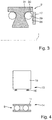
- Fig. 2 shows a bearing assembly for rotatably supporting a shaft 7 relative to a housing 8, comprising a fishing camp 9, which is designed as a rolling bearing, the rolling bearing can absorb forces in the axial and radial directions and in particular as a tapered roller bearing, especially as a double-row angular contact ball is formed. So that the rolling bearing 9 is substantially free in the radial direction, it is provided that a corrugated strip gap 10 formed radially enlarged on the outer ring 11 of the rolling bearing 9 is.
- the corrugated slit 10 is, like the inset in Fig. 2 magnified, in the radial direction, perpendicular to the axis of rotation 1, enlarged and has a radial extent h, which is approximately three to four times the usual extent h '.
- the rolling bearing 9 is substantially free in the radial direction
- a corrugated strip 12 with reduced rigidity in particular with reduced wave number w per distance in the direction of rotation and / or with increased wave amplitude at the outer ring 11 of the rolling bearing 9 is arranged.
- the corrugated strip 12 is formed as a thin metal sheet, which rotates about the axis of rotation 1 of the shaft and has waves.
- the amplitude h of the waves which corresponds to the extension of the corrugated strip gap 10 in the radial direction, is increased, and further that the number of waves per distance in the direction of rotation relative to a Comparative wave band 13 comparable wave amplitude increased, for example, by an integer factor of about 3 to 5, is.
- a corrugated strip as a composite of two mutually attached partial corrugated strips, wherein each of the two partial corrugated strips rotates around the axis of rotation 1, so that the composite of the two partial corrugated strips has a reduced rigidity relative to the two partial corrugated strips, However, the dimensions of the partial corrugated strips retains.
- Fig. 4 shows a bearing assembly with a shaft and designed as a rolling bearing 9 fishing camp, wherein the outer ring 11 of the rolling bearing 9 is fixed to a first part 14 of a bearing holder 3, wherein a second part 15 of the bearing seat 3 between the first part 14 of the bearing seat 3 and the Housing is arranged, and wherein the two parts 14, 15 of the bearing seat 3 are resiliently supported against each other in the radial direction.
- a spring means 16 between the two parts 14, 15th provided that absorbs forces in the radial direction and suppresses a transmission of the radial forces from the first part 14 to the second part 15.
- the second part 15 is displaceably mounted in the first part 14, in particular the first part 14 overlaps the second part 15 axially on the outside, so that axially acting forces can be transmitted between the two parts 14, 15.
- Fig. 5 shows a detail of an inner ring 17 of a backup bearing for receiving a shaft 7, wherein for alignment of the inner ring 17 with respect to the shaft 7, an end face 18 of the inner ring 17 cooperates with a radially parked board surface 19 on the shaft 7 to form a pair of guide surfaces.
- the end face 18 of the inner ring 17 and the flange 19 on the shaft 7 in particular also form part of a first pair of friction surfaces formed with a second Reib lakeform formed from the outer ring of the bearing and an inner surface of a bearing receptacle, wherein the frictional properties of the two Reib lakecovere for a friction-controlled self-centering of the inner ring of the rolling bearing are adjusted relative to the shaft.
- a coating or a coating or a surface structuring is provided or the surface roughness is adjusted so that the frictional properties of the first friction surface pair are increased compared to the friction properties of the second friction surface pair.
- the friction properties of the second Reib vomcos are reduced by coatings or reduced surface roughness.
- the different frictional properties of the two friction surface pairs support alignment of the inner ring 17 relative to the shaft 7.
- Fig. 6 indicates a related to Fig. 5 modified embodiment, in which it is provided that the flange surface 19 'and the end face 18' are formed bevelled and form a pair of guide surfaces.
- the end face 18 'and the flange 19' extend parallel and close with the rotation axis 1 a high angle 20 of about 75 ° to about 80 °. Due to the tapered design of the inner ring 17 is urged into a centered position when the shaft 7 falls with the board surface 19 'in the fishing camp.
- Fig. 7 shows one opposite Fig. 5 and Fig. 6 again modified embodiment. It is envisaged that the board surface 19 'in sections encloses an angle 21 of approximately 45 ° to the axis of rotation 1, and wherein the end face 18' has a rounded portion 22 which cooperates with the tapered portion of the board surface 19 '.
- the flange 19 has a bevelled portion 23 which adjoins the lateral surface of the shaft 7 and which forms an angle of approximately 45 ° with the axis of rotation 1.
- the bevelled portion 23 of the flange 19 cooperates with a rounded portion 22 of the contour of the end face 18' of the inner ring 17, wherein the rounded portion 22 may have a circular arc profile.
- Fig. 8 shows a comparison with the embodiments Fig. 5, 6 and 7 again modified embodiment, wherein it is provided that a spring element 24 between the flange 19 'on the shaft 7 and the end face 18' of the inner ring 17 is arranged.
- the flange 19 ' is aligned substantially perpendicular to the axis of rotation 1 and comprises a receding in the axial direction shoulder 25, so that a receiving space 26 is formed for the spring element 24, which may be formed in particular as a plate spring.
- the end face 18 'of the inner ring 17 has a first, to the rotation axis 1 substantially vertical portion 27 and a rounded portion 22', which may in particular have a circular arc profile.
- the spring element 24 namely the plate spring, is arranged in the receiving space 26, which is relaxed in the normal operating state of the magnetic bearing and is tensioned when the Shaft 7 falls into the fishing camp, especially when the shaft 7 approaches the inner ring 17 of the backup bearing.
- the spring element 24 biases the inner ring 17 so that the inner ring 17 can assume a favorable centered position relative to the shaft 7.
- Fig. 3 shows an embodiment in which it is provided that the rolling bearing 9 'provided as a safety bearing is designed as a substantially axially acting ball bearing, wherein a osculation of the raceways of the balls on the outer ring 11 of the rolling bearing 9' with increasing distance from the axis of rotation 1 of the shaft increases.
- the inner ring of the ball bearing 9 ' is formed as a substantially flat disc and has a flat inner ring raceway 28 for the balls 29.
- An outer ring raceway 30 on the outer ring 11 of the ball bearing 9 ' has a profile in which an osculation of the raceway, so the radius of curvature of the track, depends on the distance to the axis of rotation 1, With increasing distance to the axis of rotation increases the osculation , so that the radius of curvature also increases and the outer ring raceway 30 is at a large distance from the rotation axis 1 to this approximately parallel or turns back to the rotation axis 1.
- the inner ring 17 is opposite the outer ring 11 approximately displaceable in the radial direction, so that the ball bearing 9 'can only absorb and transmit forces in the axial direction.
Landscapes
- Engineering & Computer Science (AREA)
- General Engineering & Computer Science (AREA)
- Mechanical Engineering (AREA)
- Rolling Contact Bearings (AREA)
- Support Of The Bearing (AREA)
Description
- Die Erfindung betrifft eine Lageranordnung mit einem Fanglager, insbesondere als Bestandteil der Lagerung der schnelldrehenden Welle eines Kompressors.
- Aus der Praxis sind Lagerungen bekannt, bei denen eine Welle drehbar in beispielsweise Magnetlagern gelagert ist. Die Lagerung umfasst eine Lageranordnung mit einem Fanglager, wobei das mindestens eine Fanglager die Welle aufnimmt, falls das Magnetlager ausfällt. Im normalen Betrieb des mindestens einen Magnetlagers ist zwischen der Mantelfläche der Welle und einer auf die Welle weisenden Mantelfläche des inneren Lagerrings des Fanglagers ein Fanglagerspalt ausgebildet.
- Problematisch ist die Aufnahme sehr schnelldrehender Wellen mit hohem Gewicht, beispielsweise die Aufnahme einer mit bis zu ca. 6000 Umdrehungen /Minute drehenden massiven Welle eines Kompressors, in einem Fanglager für den Fall des Ausfallens der Magnetlager der Lagerung. Hierbei treten sehr hohe Kräfte auf, die das Fanglager beschädigen können. Weiter fällt die Welle bezogen auf die Drehachse im normalen Betrieb der Magnetlager der Lagerung exzentrisch in das Fanglager, das somit eine am Umfang ungleichmäßig auftretende Stoßbelastung erfährt.
-
EP 1 083 349 A1 zeigt ein Magnetlager mit einem Fanglager. Das Fanglager umfasst zwei Kugellager und zwei gewellte, plattenförmige Dämpfungselemente, die in einem ringförmigen Spalt eingesetzt sind, der zwischen dem Fanglager und seinem Halterungselement ausgebildet ist. -
WO 97/13985 A1 - Es ist die Aufgabe der Erfindung, eine Lageranordnung mit einem Fanglager für eine Welle anzugeben, die insbesondere die bei der Aufnahme von schnelldrehenden, massiven Wellen auftretenden Kräfte besser aufnehmen kann.
- Diese Aufgabe wird erfindungsgemäß gelöst durch eine Lageranordnung nach dem Anspruch 1. Aufgrund der kräftemäßigen Freistellung des Wälzlagers in radialer Richtung nimmt das Wälzlager bevorzugt Kräfte nur in axialer Richtung auf, deren zentrierende Wirkung auf die in das Fanglager fallende Wirkung ausgenutzt werden kann. Das Wälzlager ist in radialer Richtung im wesentlichen als Loslager ausgebildet.
- Vorzugsweise ist vorgesehen, dass eine Lageraufnahme vorgesehen ist, an der der Außenring des Wälzlagers angeordnet ist, wobei die Lageraufnahme eine umlaufende Materialschwächung, insbesondere zwei umlaufende Nuten, aufweist. Die umlaufende Materialschwächung reduziert die Aufnahme von Kräften in axialer Richtung nur wenig, bewirkt jedoch eine gezielt eingebrachte Nachgiebigkeit von radial wirkenden Kräften.
- Vorzugsweise ist vorgesehen, dass ein Wellbandspalt an dem Außenring des Wälzlagers radial vergrößert ausgebildet ist. Die Breite des Wellbandspaltes kann beispielsweise gezielt verdoppelt oder verdreifacht sein. Aufgrund der deutlich vergrößerte Ausbildung des Wellbandspaltes weicht das als Fanglager vorgesehene Wälzlager in radialer Richtung stärker auf, wenn die Welle in das Fanglager fällt, und gibt Kräfte weniger in radialer als bevorzugt in axialer Richtung weiter. Dies gilt sowohl für den Fall, dass in dem Wellbandspalt ein Wellband angeordnet ist, wie auch für den Fall, dass kein Wellband in dem Wellbandspalt vorgesehen ist, der Wellbandspalt also freibleibt.
- Vorzugsweise ist vorgesehen, dass ein Wellband mit reduzierter Steifigkeit, insbesondere mit verminderter Wellenzahl pro Strecke in Umlaufrichtung und / oder mit vergrößerter Wellenamplitude, an dem Außenring des Wälzlagers angeordnet ist. Aufgrund der reduzierten Steifigkeit ist das Wellband gegenüber radial auftretenden Kräften sehr nachgiebig, so dass das Fanglager axiale Kräfte stärker als radiale Kräfte aufnimmt.
- Vorzugsweise ist vorgesehen, dass der Außenring des Wälzlagers an einem ersten Teil einer Lageraufnahme befestigt ist, wobei ein zweiter Teil der Lageraufnahme zwischen dem ersten Teil der Lageraufnahme und dem Gehäuse angeordnet ist, und wobei die beiden Teile der Lageraufnahme in radialer Richtung federnd aneinander abgestützt sind. Die Lageraufnahme ist ein zwischen das Fanglager und das ortsfeste Gehäuse angeordnetes Bauteil, das in radialer Richtung zweigeteilt ausgebildet ist, wobei die beiden Teile, also der bezogen auf die Drehachse der Welle radial innenliegende, erste Teil und der radial außenliegende zweite Teil federnd aneinander abgestützt sind. Das Federmittel zwischen den beiden Teilen der Lageraufnahme nimmt dabei vor allem Kräfte in radialer Richtung auf, so dass das Fanglager die Kräfte insbesondere in axialer Richtung aufnehmen und weiterleiten kann.
- Vorzugsweise ist vorgesehen, dass der Innenring des Wälzlagers mit der Welle ein erstes Reibflächenpaar und der Außenring des Wälzlagers mit einer Innenfläche einer Lageraufnahme ein zweites Reibflächenpaar ausbildet, wobei die Reibeigenschaften der beiden Reibflächenpaare für eine reibgesteuerte Selbstzentrierung des Innenrings des Wälzlagers bezogen auf die Welle eingestellt sind.
- Hinsichtlich der Ausbildung der beiden Reibflächenpaare ist vorzugsweise vorgesehen, dass die Reibeigenschaften des ersten Reibflächenpaars durch Beschichtungen, Beläge, Oberflächenrauhigkeiten bzw. Oberflächenstrukturierungen gegenüber den Reibeigenschaften des zweiten Reibflächenpaars erhöht sind.
- Hinsichtlich der Ausbildung der beiden Reibflächenpaare ist vorzugsweise weiter vorgesehen, dass die Reibeigenschaften des zweiten Reibflächenpaars durch Beschichtungen oder verminderte Oberflächenrauhigkeiten herabgesetzt sind.
- Erfindungsgemäß ist vorgesehen, dass eine Stirnfläche des Innenrings des Wälzlagers mit einer radial abgestellten Bordfläche an der Welle zusammenwirkt. Im Bereich der Stirnfläche werden insbesondere axiale Kräfte in das Wälzlager eingeleitet. Die Bordfläche und die Stirnfläche bilden ein Führungsflächenpaar aus, das zur Zentrierung des Innenrings durch die in das Fanglager einfallende Welle ausgenutzt werden kann. Insbesondere können die Stirnfläche und die Bordfläche ein erstes Reibflächenpaar ausbilden, dessen Reibeigenschaften gezielt eingestellt werden können, um eine reibungsgesteuerte Zentrierung des Innenrings relativ zu der einfallenden Welle zu erleichtern. Das ist insbesondere auch dann möglich, wenn sowohl die Stirnfläche des Innenrings als auch die Bordfläche an der Welle im wesentlichen radial, also unter einem Winkel von annähernd ca. 90°, zu der Drehachse der Welle ausgerichtet sind.
- Erfindungsgemäß ist hinsichtlich der Bordfläche und der Stirnfläche vorgesehen, dass die Bordfläche und die Stirnfläche mindestens abschnittsweise angeschrägt ausgebildet sind und ein Führungsflächenpaar ausbilden. Aufgrund der angeschrägten Ausbildung wird die zentrierte Ausrichtung des Innenrings bezüglich der einfallenden Welle unterstützt.
- Vorzugsweise ist hinsichtlich der Bordfläche und der Stirnfläche vorgesehen, dass die Bordfläche und die Stirnfläche einen Winkel, bezogen auf die Drehachse der Welle, insbesondere einen hohen Winkel von mehr als ca. 60°, speziell ca. 75° bis ca. 80°, bezogen auf die Drehachse, einschließen.
- Alternativ ist vorzugsweise vorgesehen, dass die Bordfläche abschnittsweise einen Winkel von ca. 45° zu der Drehachse einschließt, und wobei die Stirnfläche einen abgerundeten Abschnitt aufweist, der mit dem angeschrägten Abschnitt der Bordfläche zusammenwirkt. Die Stirnfläche des Innenrings ist abschnittsweise beispielsweise torusballig ausgebildet, wobei der torusballige Abschnitt mit den angeschrägten Abschnitt der Bordfläche zusammenwirkt.
- Erfindungsgemäß ist vorgesehen, dass ein Federelement zwischen der Bordfläche und der Stirnfläche angeordnet ist. Das Federelement wird gespannt, wenn die Welle mit der Bordfläche in das Wälzlager mit der. Stirnfläche des Innenrings fällt und unterstützt die Ausrichtung des Innenrings bezogen auf die einfallende Welle. Zur Aufnahme des Federelementes kann der Innenring einen Winkel bezogen auf die Drehachse der Welle aufweisen, beispielsweise einen Winkel von 45°, und die Bordfläche im wesentlichen senkrecht zu der Drehachse der Welle abstehen, so dass ein umlaufender Aufnahmeraum für das Federelement bereitgestellt wird.
- Alternativ zu einem Schrägrollenlager, das axiale und radiale Kräfte im wesentlichen in gleichem Maß aufnehmen kann, ist vorzugsweise vorgesehen, dass das Wälzlager als im wesentlichen axial wirkendes Kugellager ausgebildet ist, wobei eine Schmiegung der Laufbahnen der Kugeln an dem Außenring des Wälzlagers mit zunehmenden Abstand von der Drehachse der Welle zunimmt. Bei den hohen Drehzahl, die auftreten, wenn die Welle in dem Fanglager aufgenommen wird, stellt die mit zunehmenden Abstand von der Drehachse zunehmende Schmiegung sicher, dass die Wälzkörper in dem Wälzlager gehalten werden. Der Innenring kann in diesem Fall im wesentlichen eben ausgebildet sein.
- Weitere Vorteile und Merkmale ergeben sich aus den abhängigen Ansprüchen sowie aus der folgenden Beschreibung von bevorzugten Ausführungsbeispielen der Erfindung.
- Die Erfindung wird im folgenden unter Bezugnahme auf die anliegenden Zeichnungen näher beschrieben und erläutert.
-
- Fig. 1
- zeigt schematisch einen Querschnitt durch ein erstes Ausführungsbeispiel einer Lageranordnung,
- Fig. 2
- zeigt schematisch einen Querschnitt durch ein zweites Ausführungsbeispiel einer Lageranordnung, wobei rechts unten das Detail 'X' vergrößert dargestellt ist,
- Fig. 3
- zeigt einen ausschnittsweisen Querschnitt durch ein drittes Ausführungsbeispiel einer Lageranordnung,
- Fig. 4
- zeigt einen ausschnittsweisen Querschnitt durch ein viertes Ausführungsbeispiel einer Lageranordnung,
- Fig. 5
- zeigt ausschnittsweise einen Querschnitt durch ein fünftes Ausführungsbeispiel einer Lageranordnung,
- Fig. 6
- zeigt ausschnittsweise einen Querschnitt durch ein sechstes Ausführungsbeispiel einer Lageranordnung, und
- Fig. 7
- zeigt ausschnittsweise einen Querschnitt durch ein siebtes Ausführungsbeispiel einer Lageranordnung,
- Fig. 8
- zeigt ausschnittsweise einen Querschnitt durch ein erfindungsgemäßes Ausführungsbeispiel einer Lageranordnung.
- Die Ausführungsbeispiele der
Figuren 1 bis 7 entsprechen nicht der Erfindung. -
Fig. 1 zeigt eine Lageranordnung, bei der eine Welle um eine Drehachse 1 drehbar mittels Magnetlagern gelagert wird. Die Lageranordnung umfasst mindestens ein Fanglager, das als Wälzlager, speziell aus zweireihiges Schrägkugellager, ausgebildet ist und Kräfte sowohl in axialer als auch in radialer Richtung aufnehmen kann. Ein Außenring des Wälzlagers ist an einer auf die Drehachse 1 weisenden Innenfläche 2 einer Lageraufnahme 3 angeordnet. Die Lageraufnahme 3 ist mit einer Außenfläche 4 an einem ortsfesten Gehäuse angeordnet. Ein Innenring des Wälzlagers ist durch einen Fanglagerspalt von der Mantelfläche der Welle beabstandet, so lange die Welle in den Magnetlagern gelagert ist. - Die Lageranordnung ist Teil der Lagerung einer Welle eines Kompressors, der mit Drehzahlen von ca. 6000 Undrehungen / Minute dreht und massiv ausgebildet ist. Fällt das Magnetlager aus, fällt die Welle in das Fanglager.
- Das Wälzlager ist in radialer Richtung im wesentlichen freigestellt, kann also Kräfte insbesondere in axialer Richtung, dagegen in radialer Richtung nur beschränkt aufnehmen und an das Gehäuse weiterleiten. Das Wälzlager ist damit in axialer Richtung steif und in radialer Richtung, senkrecht zu der Erstreckung der Drehachse 1 der Welle, nachgiebig ausgestaltet.
- Um das Wälzlager in radialer Richtung im wesentlichen freigestellt anzuordnen, ist vorgesehen, dass die Lageraufnahme 3, an der der Außenring des Wälzlagers angeordnet ist, eine die Drehachse 1 umlaufende Materialschwächung, insbesondere zwei umlaufende Nuten 5, 6, aufweist. Die erste Nut 5 ist an der einen Seite und die zweite Nut an der gegenüberliegenden zweiten Seite 6 der Lageraufnahme 3 ausgebildet, ist jeweils ca. drei Viertel der Erstreckung der Lageraufnahme 3 in Richtung der Drehachse 1 tief, so dass sich die tiefen Abschnitte der beiden Nuten 5, 6 in Blickrichtung senkrecht zu der Drehachse 1 überlappen. Die Nuten 5, 6 reduzieren die Fähigkeit der Lageraufnahme 3 zur Übertragung von axial, parallel zu der Drehachse 1 auftretenden Kräften nur gering. Die Nuten 5, 6 setzen jedoch die Übertragung radial wirkender Kräfte an das Gehäuse deutlich herab.
- Die nachfolgend beschriebenen Ausführungsbeispiele beschreiben weitere Möglichkeiten, mit denen vorgesehen sein kann, dass das Wälzlager in radialer Richtung im wesentlichen freigestellt ist. Dabei bezeichnen gleiche Bezugsziffern gleich oder in ihrer technischen Wirkung vergleichbare Merkmale.
-
Fig. 2 zeigt eine Lageranordnung zur drehbaren Lagerung einer Welle 7 gegenüber einem Gehäuse 8, umfassend ein Fanglager 9, das als Wälzlager ausgebildet ist, wobei das Wälzlager Kräfte in axialer und radialer Richtung aufnehmen kann und insbesondere als Schrägrollenlager, speziell als zweireihiges Schrägkugellager, ausgebildet ist. Damit das Wälzlager 9 in radialer Richtung im wesentlichen freigestellt ist, ist vorgesehen, dass ein Wellbandspalt 10 an dem Außenring 11 des Wälzlagers 9 radial vergrößert ausgebildet ist. Der Wellbandspalt 10 ist, wie das Inset inFig. 2 vergrößert darstellt, in radialer Richtung, senkrecht zu der Drehachse 1, vergrößert und weist eine radiale Erstreckung h auf, die das ca. Drei- bis Vierfache der üblichen Erstreckung h' beträgt. - Als weitere, ergänzende Maßnahme, damit das Wälzlager 9 in radialer Richtung im wesentlichen freigestellt ist, ist vorgesehen, dass in dem Wellbandspalt 10 ein Wellband 12 mit reduzierter Steifigkeit, insbesondere mit verminderter Wellenzahl w pro Strecke in Umlaufrichtung und / oder mit vergrößerter Wellenamplitude, an dem Außenring 11 des Wälzlagers 9 angeordnet ist. Das Wellband 12 ist als dünnes Metallblech ausgebildet, das die Drehachse 1 der Welle umläuft und Wellen aufweist. Um die Steifigkeit des Wellbandes 12 bei vergleichbarer Blechdicke zu reduzieren, ist vorgesehen, dass die Amplitude h der Wellen, die der Erstreckung des Wellbandspaltes 10 in radialer Richtung entspricht, vergrößert ist, sowie weiter, dass die Zahl der Welle pro Strecke in Umlaufrichtung gegenüber einem Vergleichs-Wellband 13 vergleichbarer Wellenamplitude vergrößert, beispielsweise um einen ganzzahligen Faktor von ca. 3 bis 5, ist.
- Alternativ kann vorgesehen sein, ein Wellband als Verbund zweier aneinander befestigter Teil-Wellbänder auszubilden, wobei jedes der beiden Teil-Wellbänder die Drehachse 1 umläuft, so dass der Verbund aus den beiden Teil-Wellbändern eine gegenüber den beiden Teil-Wellbändern reduzierte Steifigkeit aufweist, die Abmessungen der Teil-Wellbänder jedoch beibehält.
-
Fig. 4 zeigt eine Lageranordnung mit einer Welle sowie einem als Wälzlager 9 ausgebildeten Fanglager, wobei der Außenring 11 des Wälzlagers 9 an einem ersten Teil 14 einer Lageraufnahme 3 befestigt ist, wobei ein zweiter Teil 15 der Lageraufnahme 3 zwischen dem ersten Teil 14 der Lageraufnahme 3 und dem Gehäuse angeordnet ist, und wobei die beiden Teile 14, 15 der Lageraufnahme 3 in radialer Richtung federnd aneinander abgestützt sind. Insbesondere ist ein Federmittel 16 zwischen den beiden Teilen 14, 15 vorgesehen, das Kräfte in radialer Richtung aufnimmt und eine Übertragung der radialen Kräfte von dem ersten Teil 14 zu dem zweiten Teil 15 unterdrückt. Das zweite Teil 15 ist in dem ersten Teil 14 verschieblich gelagert, insbesondere übergreift das erste Teil 14 das zweite Teil 15 axial außenseitig, so dass axial wirkende Kräfte zwischen den beiden Teilen 14, 15 übertragen werden können. -
Fig. 5 zeigt ausschnittsweise einen Innenring 17 eines Fanglagers zur Aufnahme einer Welle 7, wobei zur Ausrichtung des Innenrings 17 bezüglich der Welle 7 eine Stirnfläche 18 des Innenrings 17 mit einer radial abgestellten Bordfläche 19 an der Welle 7 zusammenwirkt, um ein Führungsflächenpaar auszubilden. - Die Stirnfläche 18 des Innenrings 17 sowie die Bordfläche 19 an der Welle 7 bilden insbesondere auch einen Teil eines ersten Reibflächenpaares aus, das mit einem zweiten Reibflächenpaar, gebildet aus dem Außenring des Wälzlagers und einer Innenfläche einer Lageraufnahme, wobei die Reibeigenschaften der beiden Reibflächenpaare für eine reibgesteuerte Selbstzentrierung des Innenrings des Wälzlagers bezogen auf die Welle eingestellt sind. Insbesondere ist vorgesehen, dass an der Welle 7, auch im Bereich der Bordfläche 19, sowie an der Stirnfläche 18 des Innenrings 17 sowie an der Mantelfläche des Innenrings 17, die mit der Mantelfläche der Welle 7 in Kontakt kommt, eine Beschichtung oder ein Belag oder eine Oberflächenstrukturierung vorgesehen ist bzw. die Oberflächenrauhigkeit so eingestellt ist, dass die Reibeigenschaften des ersten Reibflächenpaars gegenüber den Reibeigenschaften des zweiten Reibflächenpaars erhöht sind.
- Weiter ist vorgesehen, dass die Reibeigenschaften des zweiten Reibflächenpaars durch Beschichtungen oder verminderte Oberflächenrauhigkeiten herabgesetzt sind. Die unterschiedlichen Reibeigenschaften der beiden Reibflächenpaare unterstützen eine Ausrichtung des Innenrings 17 relativ zu der Welle 7.
-
Fig. 6 zeigt ein bezogen aufFig. 5 abgewandeltes Ausführungsbeispiel, bei dem vorgesehen ist, dass die Bordfläche 19' und die Stirnfläche 18' angeschrägt ausgebildet sind und ein Führungsflächenpaar ausbilden. Die Stirnfläche 18' sowie die Bordfläche 19' verlaufen parallel und schließen mit der Drehachse 1 einen hohen Winkel 20 von ca. 75° bis ca. 80° ein. Aufgrund der angeschrägten Ausbildung wird der Innenring 17 in eine zentrierte Stellung gedrängt, wenn die Welle 7 mit der Bordfläche 19' in das Fanglager fällt. -
Fig. 7 zeigt ein gegenüberFig. 5 und Fig. 6 wiederum abgewandeltes Ausführungsbeispiel. Es ist vorgesehen, dass die Bordfläche 19' abschnittsweise einen Winkel 21 von ca. 45° zu der Drehachse 1 einschließt, und wobei die Stirnfläche 18' einen abgerundeten Abschnitt 22 aufweist, der mit dem angeschrägten Abschnitt der Bordfläche 19' zusammenwirkt. - Die Bordfläche 19' weist einen angeschrägten Abschnitt 23 auf, der an die Mantelfläche der Welle 7 angrenzt und der mit der Drehachse 1 einen Winkel von ca. 45° einschließt. Der angeschrägte Abschnitt 23 der Bordfläche 19' wirkt mit einem abgerundeten Abschnitt 22 der Kontur der Stirnfläche 18' des Innenrings 17 zusammen, wobei der abgerundete Abschnitt 22 ein Kreisbogenprofil aufweisen kann.
-
Fig. 8 zeigt ein gegenüber den Ausführungsbeispielen ausFig. 5, 6 und7 erneut abgewandeltes Ausführungsbeispiel, wobei vorgesehen ist, dass ein Federelement 24 zwischen der Bordfläche 19' an der Welle 7 und der Stirnfläche 18' des Innenrings 17 angeordnet ist. - Die Bordfläche 19' ist im wesentlichen senkrecht zu der Drehachse 1 ausgerichtet und umfasst einen in axialer Richtung zurückweichenden Absatz 25, so dass ein Aufnahmeraum 26 für das Federelement 24 ausgebildet wird, das insbesondere als Tellerfeder ausgebildet sein kann.
- Die Stirnfläche 18' des Innenrings 17 weist einen ersten, zu der Drehachse 1 im wesentlichen senkrechten Abschnitt 27 sowie einen abgerundeten Abschnitt 22' auf, der insbesondere ein Kreisbogenprofil aufweisen kann. Zwischen den abgerundeten Abschnitt 22', dem Absatz 25 an der Bordfläche 19' und der Mantelfläche der Welle 7 ist in dem Aufnahmeraum 26 das Federelement 24, nämlich die Tellerfeder, angeordnet, die im normalen Betriebszustand der Magnetlager entspannt ist und gespannt wird, wenn die Welle 7 in das Fanglager fällt, insbesondere, wenn die Welle 7 sich dem Innenring 17 des Fanglagers nähert. Das Federelement 24 spannt den Innenring 17 so, dass der Innenring 17 bezogen auf die Welle 7 eine günstige zentrierte Stellung einnehmen kann.
-
Fig. 3 zeigt ein Ausführungsbeispiel, bei dem vorgesehen ist, dass das als Fanglager vorgesehene Wälzlager 9' als im wesentlichen axial wirkendes Kugellager ausgebildet ist, wobei eine Schmiegung der Laufbahnen der Kugeln an dem Außenring 11 des Wälzlagers 9' mit zunehmenden Abstand von der Drehachse 1 der Welle zunimmt. - Das Kugellager 9' nimmt Kräfte in radialer Richtung nur begrenzt auf und weist einen Druckwinkel auf, der mit der Drehachse einen Winkel von ca. 30° einschließt. Der Innenring des Kugellagers 9' ist als im wesentlichen ebene Scheibe ausgebildet und weist einen flache Innenring-Laufbahn 28 für die Kugeln 29 auf.
- Eine Außenring-Laufbahn 30 an dem Außenring 11 des Kugellagers 9' weist ein Profil auf, bei dem eine Schmiegung der Laufbahn, also der Krümmungsradius der Laufbahn, von dem Abstand zu der Drehachse 1 abhängt, Mit zunehmende Abstand zu der Drehachse nimmt die Schmiegung zu, so dass der Krümmungsradius ebenfalls zunimmt und die Außenring-Laufbahn 30 in großen Abstand von der Drehachse 1 zu dieser annähernd parallel verläuft bzw. sich wieder hin zu der Drehachse 1 wendet. Der Innenring 17 ist gegenüber dem Außenring 11 annähernd in radialer Richtung verschieblich, so dass das Kugellager 9' nur Kräfte in axialer Richtung aufnehmen und übertragen kann.
-
- 1
- Drehachse
- 2
- Innenfläche
- 3
- Lageraufnahme
- 4
- Außenfläche
- 5
- Nut
- 6
- Nut
- 7
- Welle
- 8
- Gehäuse
- 9
- Fanglager
- 10
- Wellbandspalt
- 11
- Außenring
- 12
- Wellband
- 13
- Vergleichs-Wellband
- 14
- erstes Teil der Lageraufnahme 3
- 15
- zweites Teil der Lageraufnahme 3
- 16
- Federmittel
- 17
- Innenring
- 18, 18'
- Stirnfläche
- 19, 19'
- Bordfläche
- 20
- Winkel
- 21
- Winkel
- 22, 22'
- abgerundeter Abschnitt
- 23
- angeschrägter Abschnitt
- 24
- Federelement
- 25
- Absatz
- 26
- Aufnahmeraum
- 27
- senkrechter Abschnitt
- 28
- Innenring-Laufbahn
- 29
- Kugel
- 30
- Außenring-Laufbahn
Claims (3)
- Lageranordnung zur drehbaren Lagerung einer Welle (7) gegenüber einem Gehäuse (8), umfassend eine Welle (7), ein Gehäuse (8) und ein Fanglager (9), das als Wälzlager ausgebildet ist,
wobei das Wälzlager, welches einen Innenring (17) und einen Außenring (11) aufweist, Kräfte in axialer und radialer Richtung aufnehmen kann und insbesondere als Schrägrollenlager oder als zweireihiges Schrägkugellager ausgebildet ist,
wobei das Wälzlager (9) in radialer Richtung im wesentlichen freigestellt ist,
wobei eine Stirnfläche (18) des Innenrings (17) des Wälzlagers (9) mit einer radial abgestellten Bordfläche (19) an der Welle (7) zusammenwirkt,
wobei zumindest die Bordfläche (19') mindestens abschnittsweise angeschrägt ausgebildet ist, und
wobei die Stirnfläche (18') einen abgerundeten Abschnitt (22) aufweist, der mit dem angeschrägten Abschnitt (23) der Bordfläche (19') zusammenwirkt,
dadurch gekennzeichnet, dass der angeschrägte Abschnitt (23) der Bordfläche (19') von einem Federelement (24) gebildet ist. - Lageranordnung nach Anspruch 1, dadurch gekennzeichnet, dass die angeschrägte Bordfläche (19') mit der Drehachse (1) des Wälzlagers (9) einen Winkel (21) von 45° einschließt.
- Lagerung, insbesondere Lagerung einer Welle eines Kompressors, umfassend eine Lageranordnung nach Anspruch 1 oder 2.
Applications Claiming Priority (2)
| Application Number | Priority Date | Filing Date | Title |
|---|---|---|---|
| DE102011101307 | 2011-05-12 | ||
| PCT/EP2012/056954 WO2012152539A1 (de) | 2011-05-12 | 2012-04-17 | Lageranordnung mit einem fanglager, insbesondere für eine lagerung der schnelldrehenden welle eines kompressors |
Publications (2)
| Publication Number | Publication Date |
|---|---|
| EP2707611A1 EP2707611A1 (de) | 2014-03-19 |
| EP2707611B1 true EP2707611B1 (de) | 2017-06-28 |
Family
ID=46001198
Family Applications (1)
| Application Number | Title | Priority Date | Filing Date |
|---|---|---|---|
| EP12716349.1A Not-in-force EP2707611B1 (de) | 2011-05-12 | 2012-04-17 | Lageranordnung mit einem fanglager, insbesondere für eine lagerung der schnelldrehenden welle eines kompressors |
Country Status (5)
| Country | Link |
|---|---|
| US (1) | US20140072253A1 (de) |
| EP (1) | EP2707611B1 (de) |
| CN (1) | CN103534499B (de) |
| RU (1) | RU2013155175A (de) |
| WO (1) | WO2012152539A1 (de) |
Families Citing this family (8)
| Publication number | Priority date | Publication date | Assignee | Title |
|---|---|---|---|---|
| EP2770222A1 (de) * | 2013-02-20 | 2014-08-27 | Sulzer Pump Solutions AB | Maschine mit Sicherheitslager |
| EP2808551B1 (de) * | 2013-05-30 | 2020-01-08 | Nuovo Pignone S.r.l. | Rotationsmaschine mit mindestens einem aktiven Magnetlager und Hilfswälzlagern |
| DE102013210215A1 (de) | 2013-06-03 | 2014-12-04 | Schaeffler Technologies Gmbh & Co. Kg | Lageranordnung mit einem Fanglager |
| EP3327302B1 (de) * | 2016-11-28 | 2019-11-13 | Skf Magnetic Mechatronics | Landungslageranordnung und mit solch einer anordnung ausgerüstete drehmaschine |
| EP3652456B1 (de) | 2017-07-12 | 2021-06-09 | Johnson Controls Technology Company | Selbstzentrierende hilfslager in einer magnetlagerpatrone |
| EP3633217A1 (de) * | 2018-10-02 | 2020-04-08 | Berlin Heart GmbH | Lagerbaugruppe und rotationsfluidpumpe |
| WO2021004779A1 (de) * | 2019-07-05 | 2021-01-14 | Rollax Gmbh & Co. Kg | Lageranordnung für eine schneckenwelle |
| CN211501371U (zh) * | 2019-12-26 | 2020-09-15 | 南京磁谷科技有限公司 | 一种提高磁轴承阻尼的轴承座结构 |
Citations (1)
| Publication number | Priority date | Publication date | Assignee | Title |
|---|---|---|---|---|
| WO1997013985A1 (en) * | 1995-10-11 | 1997-04-17 | Seiko Seiki Kabushiki Kaisha | Magnetic bearing device |
Family Cites Families (13)
| Publication number | Priority date | Publication date | Assignee | Title |
|---|---|---|---|---|
| US1467378A (en) * | 1921-04-16 | 1923-09-11 | Skayef Ball Bearing Company | Ball bearing |
| FR2452025A1 (fr) * | 1979-03-20 | 1980-10-17 | Aerospatiale | Palier a roulement a jeu axial pratiquement nul |
| FR2452693A1 (fr) * | 1979-03-30 | 1980-10-24 | Aerospatiale | Dispositif de verrouillage temporaire pour volant d'inertie |
| US4312628A (en) * | 1979-05-21 | 1982-01-26 | Cambridge Thermionic Corporation | Turbomolecular vacuum pump having virtually zero power magnetic bearing assembly with single axis servo control |
| DE3141841A1 (de) * | 1981-10-22 | 1983-05-05 | Brown, Boveri & Cie Ag, 6800 Mannheim | "zentrier- und fangvorrichtung fuer beruehrungslos gelagerte rotoren" |
| DE3407269A1 (de) * | 1984-02-28 | 1985-08-29 | Siemens AG, 1000 Berlin und 8000 München | Drehanoden-roentgenroehre |
| US5531522A (en) * | 1987-05-29 | 1996-07-02 | Kmc, Inc. | Fluid dampened support having variable stiffness and damping |
| JPH1182522A (ja) * | 1997-09-17 | 1999-03-26 | Ntn Corp | 磁気軸受装置のタッチダウン軸受 |
| JP4426049B2 (ja) * | 1999-03-31 | 2010-03-03 | エドワーズ株式会社 | 磁気軸受装置及び真空ポンプ |
| JP2000291655A (ja) * | 1999-04-09 | 2000-10-20 | Nsk Ltd | 磁気軸受の保護用転がり軸受 |
| US6524005B2 (en) * | 2001-06-04 | 2003-02-25 | Honeywell International, Inc. | Touchdown bearing assembly with actuator ring assembly |
| WO2002103215A1 (fr) * | 2001-06-15 | 2002-12-27 | Societe De Mecanique Magnetique | Palier de secours insensible a la charge axiale |
| US20080206079A1 (en) * | 2007-02-27 | 2008-08-28 | Jtekt Corporation | Turbo-molecular pump and touchdown bearing device |
-
2012
- 2012-04-17 WO PCT/EP2012/056954 patent/WO2012152539A1/de not_active Ceased
- 2012-04-17 EP EP12716349.1A patent/EP2707611B1/de not_active Not-in-force
- 2012-04-17 CN CN201280022904.3A patent/CN103534499B/zh not_active Expired - Fee Related
- 2012-04-17 RU RU2013155175/11A patent/RU2013155175A/ru not_active Application Discontinuation
- 2012-04-17 US US14/116,849 patent/US20140072253A1/en not_active Abandoned
Patent Citations (1)
| Publication number | Priority date | Publication date | Assignee | Title |
|---|---|---|---|---|
| WO1997013985A1 (en) * | 1995-10-11 | 1997-04-17 | Seiko Seiki Kabushiki Kaisha | Magnetic bearing device |
Also Published As
| Publication number | Publication date |
|---|---|
| CN103534499A (zh) | 2014-01-22 |
| US20140072253A1 (en) | 2014-03-13 |
| RU2013155175A (ru) | 2015-06-20 |
| CN103534499B (zh) | 2016-02-03 |
| EP2707611A1 (de) | 2014-03-19 |
| WO2012152539A1 (de) | 2012-11-15 |
Similar Documents
| Publication | Publication Date | Title |
|---|---|---|
| WO2012152539A1 (de) | Lageranordnung mit einem fanglager, insbesondere für eine lagerung der schnelldrehenden welle eines kompressors | |
| EP2640990B1 (de) | Lagervorrichtung mit einem fanglager | |
| WO2008131721A2 (de) | Mehrreihiges grosswälzlager, insbesondere axial-radiallager zur hauptlagerung der rotorwelle einer windkraftanlage | |
| DE102013210043A1 (de) | Pendelrolle für eine Fliehkraftpendeleinrichtung undFliehkraftpendeleinrichtung mit einer Pendelrolle | |
| EP3332135B1 (de) | Verfahren und vorrichtung zur herstellung eines schrägrollenlagers | |
| EP3332136B1 (de) | Verfahren und vorrichtung zur herstellung eines schrägrollenlagers | |
| WO2007147386A2 (de) | Winkeleinstellbares wälzlager | |
| EP2707612B1 (de) | Lageranordnung mit einem fanglager, insbesondere für eine lagerung einer schnelldrehenden welle | |
| DE102013010599A1 (de) | Wälzlager, insbesondere für Tunnelbohrmaschine | |
| WO2014194899A1 (de) | Lageranordnung mit einem fanglager | |
| DE4224695A1 (de) | Wälzlager | |
| DE4322729C1 (de) | Drehlageranordnung mit Wälz-Gleitlager-Kombination | |
| WO2018086648A1 (de) | Fliehkraftpendel | |
| WO2012126743A1 (de) | Lageranordnung mit einem fanglager | |
| DE102010011462A1 (de) | Kegelrollenlager mit profilierter Laufbahn | |
| DE102010021813B4 (de) | Stoßfestes Schrägkugellager | |
| EP1812721A1 (de) | Kegelrollenlager | |
| WO2014023519A1 (de) | Vakuumpumpe | |
| DE102008030466B3 (de) | Lageranordnung | |
| DE102016211144A1 (de) | Zweireihiges Kegelrollenlager, sowie unter Einschluss desselben realisierte Lageranordnung, insbesondere für einen Ritzelkopf | |
| EP3004674B1 (de) | Lageranordnung mit einem fanglager | |
| DE102012207070A1 (de) | Anordnung zur spielfreien Lagerung einer Welle | |
| DE102016212376A1 (de) | Lagersitz mit reduzierter Steifigkeit | |
| WO2024017431A1 (de) | Zweireihiges pendelrollenlager | |
| DE102010020631A1 (de) | Radialrollenlager |
Legal Events
| Date | Code | Title | Description |
|---|---|---|---|
| PUAI | Public reference made under article 153(3) epc to a published international application that has entered the european phase |
Free format text: ORIGINAL CODE: 0009012 |
|
| 17P | Request for examination filed |
Effective date: 20131212 |
|
| AK | Designated contracting states |
Kind code of ref document: A1 Designated state(s): AL AT BE BG CH CY CZ DE DK EE ES FI FR GB GR HR HU IE IS IT LI LT LU LV MC MK MT NL NO PL PT RO RS SE SI SK SM TR |
|
| DAX | Request for extension of the european patent (deleted) | ||
| RAP1 | Party data changed (applicant data changed or rights of an application transferred) |
Owner name: SCHAEFFLER TECHNOLOGIES AG & CO. KG |
|
| 17Q | First examination report despatched |
Effective date: 20160614 |
|
| GRAP | Despatch of communication of intention to grant a patent |
Free format text: ORIGINAL CODE: EPIDOSNIGR1 |
|
| RIC1 | Information provided on ipc code assigned before grant |
Ipc: F16C 39/02 20060101ALI20170119BHEP Ipc: F16C 32/04 20060101ALI20170119BHEP Ipc: F16C 27/04 20060101AFI20170119BHEP Ipc: F16C 27/08 20060101ALI20170119BHEP |
|
| INTG | Intention to grant announced |
Effective date: 20170221 |
|
| GRAS | Grant fee paid |
Free format text: ORIGINAL CODE: EPIDOSNIGR3 |
|
| GRAA | (expected) grant |
Free format text: ORIGINAL CODE: 0009210 |
|
| AK | Designated contracting states |
Kind code of ref document: B1 Designated state(s): AL AT BE BG CH CY CZ DE DK EE ES FI FR GB GR HR HU IE IS IT LI LT LU LV MC MK MT NL NO PL PT RO RS SE SI SK SM TR |
|
| REG | Reference to a national code |
Ref country code: GB Ref legal event code: FG4D Free format text: NOT ENGLISH |
|
| REG | Reference to a national code |
Ref country code: CH Ref legal event code: EP |
|
| REG | Reference to a national code |
Ref country code: AT Ref legal event code: REF Ref document number: 905135 Country of ref document: AT Kind code of ref document: T Effective date: 20170715 |
|
| REG | Reference to a national code |
Ref country code: IE Ref legal event code: FG4D Free format text: LANGUAGE OF EP DOCUMENT: GERMAN |
|
| REG | Reference to a national code |
Ref country code: DE Ref legal event code: R096 Ref document number: 502012010656 Country of ref document: DE |
|
| PG25 | Lapsed in a contracting state [announced via postgrant information from national office to epo] |
Ref country code: NO Free format text: LAPSE BECAUSE OF FAILURE TO SUBMIT A TRANSLATION OF THE DESCRIPTION OR TO PAY THE FEE WITHIN THE PRESCRIBED TIME-LIMIT Effective date: 20170928 Ref country code: FI Free format text: LAPSE BECAUSE OF FAILURE TO SUBMIT A TRANSLATION OF THE DESCRIPTION OR TO PAY THE FEE WITHIN THE PRESCRIBED TIME-LIMIT Effective date: 20170628 Ref country code: HR Free format text: LAPSE BECAUSE OF FAILURE TO SUBMIT A TRANSLATION OF THE DESCRIPTION OR TO PAY THE FEE WITHIN THE PRESCRIBED TIME-LIMIT Effective date: 20170628 Ref country code: LT Free format text: LAPSE BECAUSE OF FAILURE TO SUBMIT A TRANSLATION OF THE DESCRIPTION OR TO PAY THE FEE WITHIN THE PRESCRIBED TIME-LIMIT Effective date: 20170628 Ref country code: GR Free format text: LAPSE BECAUSE OF FAILURE TO SUBMIT A TRANSLATION OF THE DESCRIPTION OR TO PAY THE FEE WITHIN THE PRESCRIBED TIME-LIMIT Effective date: 20170929 |
|
| REG | Reference to a national code |
Ref country code: NL Ref legal event code: MP Effective date: 20170628 |
|
| REG | Reference to a national code |
Ref country code: LT Ref legal event code: MG4D |
|
| PG25 | Lapsed in a contracting state [announced via postgrant information from national office to epo] |
Ref country code: SE Free format text: LAPSE BECAUSE OF FAILURE TO SUBMIT A TRANSLATION OF THE DESCRIPTION OR TO PAY THE FEE WITHIN THE PRESCRIBED TIME-LIMIT Effective date: 20170628 Ref country code: LV Free format text: LAPSE BECAUSE OF FAILURE TO SUBMIT A TRANSLATION OF THE DESCRIPTION OR TO PAY THE FEE WITHIN THE PRESCRIBED TIME-LIMIT Effective date: 20170628 Ref country code: BG Free format text: LAPSE BECAUSE OF FAILURE TO SUBMIT A TRANSLATION OF THE DESCRIPTION OR TO PAY THE FEE WITHIN THE PRESCRIBED TIME-LIMIT Effective date: 20170928 Ref country code: NL Free format text: LAPSE BECAUSE OF FAILURE TO SUBMIT A TRANSLATION OF THE DESCRIPTION OR TO PAY THE FEE WITHIN THE PRESCRIBED TIME-LIMIT Effective date: 20170628 Ref country code: RS Free format text: LAPSE BECAUSE OF FAILURE TO SUBMIT A TRANSLATION OF THE DESCRIPTION OR TO PAY THE FEE WITHIN THE PRESCRIBED TIME-LIMIT Effective date: 20170628 |
|
| PG25 | Lapsed in a contracting state [announced via postgrant information from national office to epo] |
Ref country code: SK Free format text: LAPSE BECAUSE OF FAILURE TO SUBMIT A TRANSLATION OF THE DESCRIPTION OR TO PAY THE FEE WITHIN THE PRESCRIBED TIME-LIMIT Effective date: 20170628 Ref country code: RO Free format text: LAPSE BECAUSE OF FAILURE TO SUBMIT A TRANSLATION OF THE DESCRIPTION OR TO PAY THE FEE WITHIN THE PRESCRIBED TIME-LIMIT Effective date: 20170628 Ref country code: EE Free format text: LAPSE BECAUSE OF FAILURE TO SUBMIT A TRANSLATION OF THE DESCRIPTION OR TO PAY THE FEE WITHIN THE PRESCRIBED TIME-LIMIT Effective date: 20170628 Ref country code: CZ Free format text: LAPSE BECAUSE OF FAILURE TO SUBMIT A TRANSLATION OF THE DESCRIPTION OR TO PAY THE FEE WITHIN THE PRESCRIBED TIME-LIMIT Effective date: 20170628 |
|
| PG25 | Lapsed in a contracting state [announced via postgrant information from national office to epo] |
Ref country code: IS Free format text: LAPSE BECAUSE OF FAILURE TO SUBMIT A TRANSLATION OF THE DESCRIPTION OR TO PAY THE FEE WITHIN THE PRESCRIBED TIME-LIMIT Effective date: 20171028 Ref country code: IT Free format text: LAPSE BECAUSE OF FAILURE TO SUBMIT A TRANSLATION OF THE DESCRIPTION OR TO PAY THE FEE WITHIN THE PRESCRIBED TIME-LIMIT Effective date: 20170628 Ref country code: PL Free format text: LAPSE BECAUSE OF FAILURE TO SUBMIT A TRANSLATION OF THE DESCRIPTION OR TO PAY THE FEE WITHIN THE PRESCRIBED TIME-LIMIT Effective date: 20170628 Ref country code: SM Free format text: LAPSE BECAUSE OF FAILURE TO SUBMIT A TRANSLATION OF THE DESCRIPTION OR TO PAY THE FEE WITHIN THE PRESCRIBED TIME-LIMIT Effective date: 20170628 Ref country code: ES Free format text: LAPSE BECAUSE OF FAILURE TO SUBMIT A TRANSLATION OF THE DESCRIPTION OR TO PAY THE FEE WITHIN THE PRESCRIBED TIME-LIMIT Effective date: 20170628 |
|
| REG | Reference to a national code |
Ref country code: DE Ref legal event code: R097 Ref document number: 502012010656 Country of ref document: DE |
|
| PG25 | Lapsed in a contracting state [announced via postgrant information from national office to epo] |
Ref country code: DK Free format text: LAPSE BECAUSE OF FAILURE TO SUBMIT A TRANSLATION OF THE DESCRIPTION OR TO PAY THE FEE WITHIN THE PRESCRIBED TIME-LIMIT Effective date: 20170628 |
|
| REG | Reference to a national code |
Ref country code: FR Ref legal event code: PLFP Year of fee payment: 7 |
|
| PLBE | No opposition filed within time limit |
Free format text: ORIGINAL CODE: 0009261 |
|
| STAA | Information on the status of an ep patent application or granted ep patent |
Free format text: STATUS: NO OPPOSITION FILED WITHIN TIME LIMIT |
|
| 26N | No opposition filed |
Effective date: 20180329 |
|
| PG25 | Lapsed in a contracting state [announced via postgrant information from national office to epo] |
Ref country code: SI Free format text: LAPSE BECAUSE OF FAILURE TO SUBMIT A TRANSLATION OF THE DESCRIPTION OR TO PAY THE FEE WITHIN THE PRESCRIBED TIME-LIMIT Effective date: 20170628 |
|
| PG25 | Lapsed in a contracting state [announced via postgrant information from national office to epo] |
Ref country code: MT Free format text: LAPSE BECAUSE OF FAILURE TO SUBMIT A TRANSLATION OF THE DESCRIPTION OR TO PAY THE FEE WITHIN THE PRESCRIBED TIME-LIMIT Effective date: 20170628 |
|
| PG25 | Lapsed in a contracting state [announced via postgrant information from national office to epo] |
Ref country code: MC Free format text: LAPSE BECAUSE OF FAILURE TO SUBMIT A TRANSLATION OF THE DESCRIPTION OR TO PAY THE FEE WITHIN THE PRESCRIBED TIME-LIMIT Effective date: 20170628 |
|
| REG | Reference to a national code |
Ref country code: CH Ref legal event code: PL |
|
| REG | Reference to a national code |
Ref country code: BE Ref legal event code: MM Effective date: 20180430 |
|
| GBPC | Gb: european patent ceased through non-payment of renewal fee |
Effective date: 20180417 |
|
| REG | Reference to a national code |
Ref country code: IE Ref legal event code: MM4A |
|
| PG25 | Lapsed in a contracting state [announced via postgrant information from national office to epo] |
Ref country code: LU Free format text: LAPSE BECAUSE OF NON-PAYMENT OF DUE FEES Effective date: 20180417 |
|
| PG25 | Lapsed in a contracting state [announced via postgrant information from national office to epo] |
Ref country code: LI Free format text: LAPSE BECAUSE OF NON-PAYMENT OF DUE FEES Effective date: 20180430 Ref country code: BE Free format text: LAPSE BECAUSE OF NON-PAYMENT OF DUE FEES Effective date: 20180430 Ref country code: GB Free format text: LAPSE BECAUSE OF NON-PAYMENT OF DUE FEES Effective date: 20180417 Ref country code: CH Free format text: LAPSE BECAUSE OF NON-PAYMENT OF DUE FEES Effective date: 20180430 |
|
| PG25 | Lapsed in a contracting state [announced via postgrant information from national office to epo] |
Ref country code: IE Free format text: LAPSE BECAUSE OF NON-PAYMENT OF DUE FEES Effective date: 20180417 |
|
| REG | Reference to a national code |
Ref country code: AT Ref legal event code: MM01 Ref document number: 905135 Country of ref document: AT Kind code of ref document: T Effective date: 20180417 |
|
| PG25 | Lapsed in a contracting state [announced via postgrant information from national office to epo] |
Ref country code: AT Free format text: LAPSE BECAUSE OF NON-PAYMENT OF DUE FEES Effective date: 20180417 |
|
| PG25 | Lapsed in a contracting state [announced via postgrant information from national office to epo] |
Ref country code: TR Free format text: LAPSE BECAUSE OF FAILURE TO SUBMIT A TRANSLATION OF THE DESCRIPTION OR TO PAY THE FEE WITHIN THE PRESCRIBED TIME-LIMIT Effective date: 20170628 |
|
| PG25 | Lapsed in a contracting state [announced via postgrant information from national office to epo] |
Ref country code: HU Free format text: LAPSE BECAUSE OF FAILURE TO SUBMIT A TRANSLATION OF THE DESCRIPTION OR TO PAY THE FEE WITHIN THE PRESCRIBED TIME-LIMIT; INVALID AB INITIO Effective date: 20120417 Ref country code: PT Free format text: LAPSE BECAUSE OF FAILURE TO SUBMIT A TRANSLATION OF THE DESCRIPTION OR TO PAY THE FEE WITHIN THE PRESCRIBED TIME-LIMIT Effective date: 20170628 |
|
| PG25 | Lapsed in a contracting state [announced via postgrant information from national office to epo] |
Ref country code: CY Free format text: LAPSE BECAUSE OF FAILURE TO SUBMIT A TRANSLATION OF THE DESCRIPTION OR TO PAY THE FEE WITHIN THE PRESCRIBED TIME-LIMIT Effective date: 20170628 Ref country code: MK Free format text: LAPSE BECAUSE OF NON-PAYMENT OF DUE FEES Effective date: 20170628 |
|
| PG25 | Lapsed in a contracting state [announced via postgrant information from national office to epo] |
Ref country code: AL Free format text: LAPSE BECAUSE OF FAILURE TO SUBMIT A TRANSLATION OF THE DESCRIPTION OR TO PAY THE FEE WITHIN THE PRESCRIBED TIME-LIMIT Effective date: 20170628 |
|
| PGFP | Annual fee paid to national office [announced via postgrant information from national office to epo] |
Ref country code: FR Payment date: 20200429 Year of fee payment: 9 |
|
| PGFP | Annual fee paid to national office [announced via postgrant information from national office to epo] |
Ref country code: DE Payment date: 20200629 Year of fee payment: 9 |
|
| REG | Reference to a national code |
Ref country code: DE Ref legal event code: R119 Ref document number: 502012010656 Country of ref document: DE |
|
| PG25 | Lapsed in a contracting state [announced via postgrant information from national office to epo] |
Ref country code: FR Free format text: LAPSE BECAUSE OF NON-PAYMENT OF DUE FEES Effective date: 20210430 Ref country code: DE Free format text: LAPSE BECAUSE OF NON-PAYMENT OF DUE FEES Effective date: 20211103 |
|
| P01 | Opt-out of the competence of the unified patent court (upc) registered |
Effective date: 20230523 |