EP2706604A2 - Sekundärbatterie mit einem isolator - Google Patents
Sekundärbatterie mit einem isolator Download PDFInfo
- Publication number
- EP2706604A2 EP2706604A2 EP12805102.6A EP12805102A EP2706604A2 EP 2706604 A2 EP2706604 A2 EP 2706604A2 EP 12805102 A EP12805102 A EP 12805102A EP 2706604 A2 EP2706604 A2 EP 2706604A2
- Authority
- EP
- European Patent Office
- Prior art keywords
- insulator
- secondary battery
- battery according
- fine pores
- jelly
- Prior art date
- Legal status (The legal status is an assumption and is not a legal conclusion. Google has not performed a legal analysis and makes no representation as to the accuracy of the status listed.)
- Granted
Links
Images
Classifications
-
- H—ELECTRICITY
- H01—ELECTRIC ELEMENTS
- H01M—PROCESSES OR MEANS, e.g. BATTERIES, FOR THE DIRECT CONVERSION OF CHEMICAL ENERGY INTO ELECTRICAL ENERGY
- H01M50/00—Constructional details or processes of manufacture of the non-active parts of electrochemical cells other than fuel cells, e.g. hybrid cells
- H01M50/20—Mountings; Secondary casings or frames; Racks, modules or packs; Suspension devices; Shock absorbers; Transport or carrying devices; Holders
-
- H—ELECTRICITY
- H01—ELECTRIC ELEMENTS
- H01M—PROCESSES OR MEANS, e.g. BATTERIES, FOR THE DIRECT CONVERSION OF CHEMICAL ENERGY INTO ELECTRICAL ENERGY
- H01M10/00—Secondary cells; Manufacture thereof
- H01M10/05—Accumulators with non-aqueous electrolyte
- H01M10/052—Li-accumulators
-
- H—ELECTRICITY
- H01—ELECTRIC ELEMENTS
- H01M—PROCESSES OR MEANS, e.g. BATTERIES, FOR THE DIRECT CONVERSION OF CHEMICAL ENERGY INTO ELECTRICAL ENERGY
- H01M50/00—Constructional details or processes of manufacture of the non-active parts of electrochemical cells other than fuel cells, e.g. hybrid cells
- H01M50/10—Primary casings; Jackets or wrappings
- H01M50/102—Primary casings; Jackets or wrappings characterised by their shape or physical structure
- H01M50/107—Primary casings; Jackets or wrappings characterised by their shape or physical structure having curved cross-section, e.g. round or elliptic
-
- H—ELECTRICITY
- H01—ELECTRIC ELEMENTS
- H01M—PROCESSES OR MEANS, e.g. BATTERIES, FOR THE DIRECT CONVERSION OF CHEMICAL ENERGY INTO ELECTRICAL ENERGY
- H01M50/00—Constructional details or processes of manufacture of the non-active parts of electrochemical cells other than fuel cells, e.g. hybrid cells
- H01M50/40—Separators; Membranes; Diaphragms; Spacing elements inside cells
- H01M50/463—Separators, membranes or diaphragms characterised by their shape
- H01M50/469—Separators, membranes or diaphragms characterised by their shape tubular or cylindrical
-
- H—ELECTRICITY
- H01—ELECTRIC ELEMENTS
- H01M—PROCESSES OR MEANS, e.g. BATTERIES, FOR THE DIRECT CONVERSION OF CHEMICAL ENERGY INTO ELECTRICAL ENERGY
- H01M50/00—Constructional details or processes of manufacture of the non-active parts of electrochemical cells other than fuel cells, e.g. hybrid cells
- H01M50/50—Current conducting connections for cells or batteries
- H01M50/543—Terminals
- H01M50/552—Terminals characterised by their shape
- H01M50/559—Terminals adapted for cells having curved cross-section, e.g. round, elliptic or button cells
-
- H—ELECTRICITY
- H01—ELECTRIC ELEMENTS
- H01M—PROCESSES OR MEANS, e.g. BATTERIES, FOR THE DIRECT CONVERSION OF CHEMICAL ENERGY INTO ELECTRICAL ENERGY
- H01M50/00—Constructional details or processes of manufacture of the non-active parts of electrochemical cells other than fuel cells, e.g. hybrid cells
- H01M50/50—Current conducting connections for cells or batteries
- H01M50/572—Means for preventing undesired use or discharge
-
- H—ELECTRICITY
- H01—ELECTRIC ELEMENTS
- H01M—PROCESSES OR MEANS, e.g. BATTERIES, FOR THE DIRECT CONVERSION OF CHEMICAL ENERGY INTO ELECTRICAL ENERGY
- H01M2220/00—Batteries for particular applications
- H01M2220/20—Batteries in motive systems, e.g. vehicle, ship, plane
-
- H—ELECTRICITY
- H01—ELECTRIC ELEMENTS
- H01M—PROCESSES OR MEANS, e.g. BATTERIES, FOR THE DIRECT CONVERSION OF CHEMICAL ENERGY INTO ELECTRICAL ENERGY
- H01M50/00—Constructional details or processes of manufacture of the non-active parts of electrochemical cells other than fuel cells, e.g. hybrid cells
- H01M50/50—Current conducting connections for cells or batteries
- H01M50/543—Terminals
- H01M50/547—Terminals characterised by the disposition of the terminals on the cells
- H01M50/548—Terminals characterised by the disposition of the terminals on the cells on opposite sides of the cell
-
- Y—GENERAL TAGGING OF NEW TECHNOLOGICAL DEVELOPMENTS; GENERAL TAGGING OF CROSS-SECTIONAL TECHNOLOGIES SPANNING OVER SEVERAL SECTIONS OF THE IPC; TECHNICAL SUBJECTS COVERED BY FORMER USPC CROSS-REFERENCE ART COLLECTIONS [XRACs] AND DIGESTS
- Y02—TECHNOLOGIES OR APPLICATIONS FOR MITIGATION OR ADAPTATION AGAINST CLIMATE CHANGE
- Y02E—REDUCTION OF GREENHOUSE GAS [GHG] EMISSIONS, RELATED TO ENERGY GENERATION, TRANSMISSION OR DISTRIBUTION
- Y02E60/00—Enabling technologies; Technologies with a potential or indirect contribution to GHG emissions mitigation
- Y02E60/10—Energy storage using batteries
-
- Y—GENERAL TAGGING OF NEW TECHNOLOGICAL DEVELOPMENTS; GENERAL TAGGING OF CROSS-SECTIONAL TECHNOLOGIES SPANNING OVER SEVERAL SECTIONS OF THE IPC; TECHNICAL SUBJECTS COVERED BY FORMER USPC CROSS-REFERENCE ART COLLECTIONS [XRACs] AND DIGESTS
- Y02—TECHNOLOGIES OR APPLICATIONS FOR MITIGATION OR ADAPTATION AGAINST CLIMATE CHANGE
- Y02P—CLIMATE CHANGE MITIGATION TECHNOLOGIES IN THE PRODUCTION OR PROCESSING OF GOODS
- Y02P70/00—Climate change mitigation technologies in the production process for final industrial or consumer products
- Y02P70/50—Manufacturing or production processes characterised by the final manufactured product
-
- Y—GENERAL TAGGING OF NEW TECHNOLOGICAL DEVELOPMENTS; GENERAL TAGGING OF CROSS-SECTIONAL TECHNOLOGIES SPANNING OVER SEVERAL SECTIONS OF THE IPC; TECHNICAL SUBJECTS COVERED BY FORMER USPC CROSS-REFERENCE ART COLLECTIONS [XRACs] AND DIGESTS
- Y02—TECHNOLOGIES OR APPLICATIONS FOR MITIGATION OR ADAPTATION AGAINST CLIMATE CHANGE
- Y02T—CLIMATE CHANGE MITIGATION TECHNOLOGIES RELATED TO TRANSPORTATION
- Y02T10/00—Road transport of goods or passengers
- Y02T10/60—Other road transportation technologies with climate change mitigation effect
- Y02T10/70—Energy storage systems for electromobility, e.g. batteries
Definitions
- the present invention relates to a secondary battery. More specifically, the present invention relates to a secondary battery having a structure in which a jelly-roll having a cathode/separator/anode structure is mounted in a cylindrical battery case, wherein a plate-shaped insulator mounted on the top of the jelly-roll includes a perforated inlet enabling gas discharge and penetration of electrode terminals, a plurality of fine pores having a size that allows permeation of an electrolyte solution, but does not allow permeation of foreign materials, and a plurality of strip or bead shaped protrusions disposed in transverse and/or longitudinal directions on one or both surfaces of the insulator.
- lithium secondary batteries with high energy density, high driving voltage and superior storage and lifespan characteristics are widely used as energy sources of various electric products including mobile devices.
- the secondary battery may be divided into cylindrical and rectangular batteries mounted in cylindrical and rectangular metal cans, respectively, and a pouch-shaped battery mounted in a pouch-shaped case made of an aluminum laminate sheet.
- the cylindrical battery has advantages of relatively high capacity and superior structural stability.
- the electrode assembly mounted in the battery case is an electricity-generating device enabling charge and discharge that has a cathode/separator/anode laminate structure and is divided into a jelly-roll type in which an electrode assembly including a separator interposed between a cathode and an anode, each made of an active material-coated long sheet, is rolled, a stack-type in which a plurality of cathodes and a plurality of anodes are laminated in this order such that a separator is interposed between the cathode and the anode and a stack/folding type which is a combination of a jelly-roll type and a stack type.
- the jelly-roll-type electrode assembly has advantages of easy manufacture and high energy density per weight.
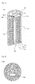
- FIG. 1 a conventional cylindrical secondary battery is shown in FIG. 1 .
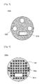
- An insulator generally used for the cylindrical secondary battery is shown in plan views in FIGS. 2 and 3 .
- a cylindrical secondary battery 100 is manufactured by mounting a jelly-roll type (rolled-type) electrode assembly 120 in a battery case 130, injecting an electrolytic solution into the battery case 130 and coupling a cap assembly 140 provided with an electrode terminal (for example, a cathode terminal; not shown) to the open top of the case 130.
- a jelly-roll type (rolled-type) electrode assembly 120 in a battery case 130, injecting an electrolytic solution into the battery case 130 and coupling a cap assembly 140 provided with an electrode terminal (for example, a cathode terminal; not shown) to the open top of the case 130.
- the electrode assembly 120 is obtained by inserting a separator 123 between a cathode 121 and an anode 122 and rolling the resulting structure into a round shape.
- a cylindrical center pin 150 is inserted into the core (center) of the jelly-roll.
- the center pin 150 is generally made of a metal to impart a predetermined strength and has a hollow-shaped cylindrical structure of a roundly bent plate material. Such a center pin 150 sets and supports the electrode assembly and serves as a passage, enabling discharge of gas generated by internal reaction during charge and discharge, and operation.
- a plate-shaped insulator 180a is mounted on the top of the electrode assembly 120, and is provided in the center thereof with an inlet 181a communicating with the through hole 151 of the center pin 150 so that gas is discharged and the cathode tap 142 of the electrode assembly 120 is connected to the cap plate 145 of the cap assembly 140.
- the insulator 180a arranged on the top of the jelly-roll is a structure that blocks a passage through which an electrolyte solution permeates into a battery in the process of injecting an electrolyte solution into the battery. For this reason, the electrolyte solution permeates the battery only through the inlet 181a communicating with the center pin 150 and a region excluding the insulator 180a, thus disadvantageously requiring a long time for injection of electrolyte and consequently causing deterioration in production efficiency.
- a partial connection member 180b having a structure in which a plurality of through pores 182b are formed around an inlet 181b is suggested.
- a secondary battery having a structure in which a jelly-roll having a cathode/separator/anode structure is mounted in a cylindrical battery case, wherein a plate-shaped insulator mounted on the top of the jelly-roll includes: a perforated inlet enabling gas discharge and penetration of electrode terminals; a plurality of fine pores having a size that allows permeation of an electrolyte solution, but does not allow permeation of foreign materials; and a plurality of strip or bead shaped protrusions disposed in transverse and/or longitudinal directions on one or both surfaces of the insulator.
- a cylindrical secondary battery is fabricated by inserting a jelly-roll into a cylindrical can, mounting an insulator on the top of the jelly-roll and performing a beading process to fix the jelly-roll.
- a beading process is carried out by applying pressure in a longitudinal direction while bending the peripheral surface of the cylindrical can using a metal.
- metals contact one another to cause deformation and fine metal fragments are thus generated.
- the insulator should facilitate injection of electrolyte solution, while not allowing permeation of foreign materials such as fine metal fragments.
- the cylindrical secondary battery can greatly improve injectability, since it allows permeation of electrolyte solution over the entire surface of the insulator through the insulator having a structure mounted on the top of the jelly-roll when the electrolyte solution is injected, and can prevent short circuit, as compared to conventional insulators having a larger diameter.
- the strip or bead shaped protrusions may be formed by pressing parts other than the protrusions. Based on such structure, mechanical properties of insulator can be improved.
- the insulator may be composed of an electrical-insulating polymer resin or an electrical-insulating polymer composite and, specifically, the polymer resin may be one or more selected from the group consisting of polyethylene (PE), polypropylene (PP), polybutylene (PB), polystyrene (PS), polyethylene terephthalate (PET), natural rubbers and synthetic rubbers.
- the polymer resin may be one or more selected from the group consisting of polyethylene (PE), polypropylene (PP), polybutylene (PB), polystyrene (PS), polyethylene terephthalate (PET), natural rubbers and synthetic rubbers.
- the fine pores have a size, providing electric insulating property, as an inherent function of insulator and allowing permeation of an electrolyte solution during injection of electrolyte solution.
- the fine pores may have a diameter of 1 ⁇ m to 100 ⁇ m.
- the fine pores may be spaced from one another by a predetermined distance over the entire surface of the insulator.
- the distance often means a distance between fine pores perforated on the insulator.
- the insulator according to the present invention may have a variety of shapes.
- the insulator comprises a material molded with a polymer resin or composite and may have a structure in which fine pores perforate through the molded material (plate-typed body).
- the insulator comprises a woven-fabric in which long fibers made of a polymer resin or composite form fine pores.
- the insulator comprises a non-woven fabric in which short fibers made of a polymer resin or composite form fine pores.
- permeation of electrolyte solution may be relatively unfavorable and deteriorated gas discharge due to surface tension and restoring force of the perforated part, as compared to woven and non-woven fabrics.
- woven and non-woven fabrics are free of a bending phenomenon resulting from formation of pressing sheets, thus advantageously enhancing processability.
- the short fibers are partially bonded through needle punching or thermal fusion, or using an adhesive agent to form a non-woven fabric.
- the non-woven fabric has a structure in which fibers are randomly entangled.
- the short fibers may be partially bonded through needle punching or thermal fusion, or using an adhesive agent, in order to fix the entangled fibers.
- the protrusions cross one another in transverse and longitudinal directions to form a checker pattern.
- the protrusions may be present difference in mechanical strength according to directions. Accordingly, preferably, the protrusions cross one another in transverse and longitudinal directions to form a checker pattern.
- the protrusions may have a structure in which an embossing pattern is present over the entire surface of the insulator. Based on the embossing pattern, mechanical strength and surface frictional force can be improved.
- the embossing pattern may have a structure in which non-thermally fused parts form protrusions by thermally fusing a part of the insulator.
- the protrusions and thermally-fused parts may be an island or continuous shape.
- the insulator comprises a non-woven fabric made of short fibers, parts bonded by thermal fusion are disposed by a predetermined distance over the entire surface of the insulator, and protrusions having a barrier shape that are not thermally fused are disposed between the bonded parts.
- the insulator has a thickness of 0.1 mm to 0.5 mm. When the thickness of the insulator is excessively small, the insulator cannot sufficiently exert insulation and, on the other hand, when the thickness is excessively large, a decrease in size of jelly-roll is induced in a battery case having a constant size and battery capacity is disadvantageously reduced.
- the secondary battery according to the present invention may be applied to a lithium secondary battery fabricated by impregnating a lithium-containing electrolyte solution in the jelly-roll.
- the present invention also provides a device comprising the secondary battery as a power source.
- the device according to the present invention may be used for mobile devices such as cellular phones and portable computers as well as electric vehicles, hybrid electric vehicles, plug-in hybrid electric vehicles and power-storing devices in terms of superior lifespan and safety.
- the secondary battery according to the present invention comprises an insulator that is provided over the entire surface thereof with fine pores and includes protrusions, thereby advantageously enabling an electrolyte solution to be permeated over the entire surface of the insulator while preventing short circuit and thus ultimately greatly improving safety, performance and lifespan of batteries.
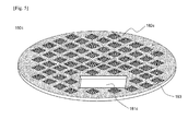
- FIG. 4 is a plan view schematically illustrating an insulator according to one embodiment of the present invention.
- FIG. 5 is a perspective view schematically illustrating an insulator according to another embodiment of the present invention.
- a secondary battery 100 has a structure in which a jelly-roll 120 having a structure of cathode 121/ separator 123/anode 122 is mounted in a cylindrical battery case 130, wherein an insulator 180 is mounted on the top of the jelly-roll 120.
- the insulator 180c is composed of polyethylene terephthalate (PET) with a thickness of about 0.4 mm, is provided at one side thereof with an inlet 181c and is provided over the entire surface thereof with a plurality of fine pores 182c having a diameter of 10 to 30 ⁇ m that are spaced from one another by a predetermined distance.
- Depressed embossing 183 structures are disposed in transverse and/or longitudinal directions to form protrusions corresponding to continuous raised embossing structures.
- an electrolyte solution permeates into the entire surface of the insulator 180c when injected, thus causing considerable improvement in injectability and preventing occurrence of short circuit. Also, through formation of protrusions based on the depressed embossing 183 structures, mechanical strength of insulator can be increased, and processability can be improved due to increase in surface frictional force.
- PET polypropylene phthalate
- the insulator was mounted on top of a jelly-roll in which a cathode/separator/anode was rolled based on a center pin and a cylindrical secondary battery of an 18650 standard (diameter 18 mm, length 65 mm) was manufactured in a state that fine metal powders generated in the process of battery assembly were arranged on the insulator.
- An insulator and a secondary battery were manufactured in the same manner as in Example 1 except that an insulator, in which a plurality of fine pores having a diameter of 100 ⁇ m were uniformly distributed by a predetermined distance of about 120 ⁇ m over the entire surface of the insulator, was prepared.
- An insulator and a secondary battery were manufactured in the same manner as in Example 1 except that a polypropylene (PP) sheet was used as a material for the insulator, instead of the polyethylene terephthalate (PET) sheet.
- PP polypropylene
- PET polyethylene terephthalate
- An insulator having a depressed embossing pattern structure was manufactured using a polyethylene terephthalate (PET) woven fabric that formed fine pores of 15 ⁇ m as a material for the insulator.
- PET polyethylene terephthalate
- An insulator and a secondary battery were manufactured in the same manner as in Example 1 except that the material for the insulator was used.
- An insulator having a depressed embossing pattern structure was manufactured using a polyethylene terephthalate (PET) woven fabric that formed fine pores of 15 ⁇ m on average as a material for the insulator.
- PET polyethylene terephthalate
- An insulator and a secondary battery were manufactured in the same manner as in Example 1 except that the material for the insulator was used.
- An insulator and a secondary battery were manufactured in the same manner as in Example 1 except that a plurality of pores was not included, as shown in FIG. 2 .
- An insulator and a secondary battery were manufactured in the same manner as in Example 1 except that three through pores with a diameter of 2.5 mm were formed, as shown in FIG. 3 .
- An insulator and secondary battery were manufactured in the same manner as in Example 1 except that a plurality of fine pores having a diameter of 150 ⁇ m were uniformly distributed by a predetermined distance of about 120 ⁇ m over the entire surface of the insulator.
- An insulator and a secondary battery were manufactured in the same manner as in Comparative Example 1 except that polypropylene (PP) was used as a material for the insulator, instead of polyethylene terephthalate (PET).
- PP polypropylene
- PET polyethylene terephthalate
- An insulator and a secondary battery were manufactured in the same manner as in Comparative Example 1 except that a polyethylene terephthalate (PET) woven fabric that did not form fine pores was used as a material for the insulator.
- PET polyethylene terephthalate
- the secondary batteries manufactured in Examples 1 to 5 and Comparative Examples 1 to 5 were subjected to electrolyte solution impregnation testing.
- the results are shown in Table 1 below.
- the electrolyte solution impregnation testing was carried out by injecting a 1M LiPF 6 carbonate electrolyte solution into the manufactured cylindrical battery case, measuring a time taken until impregnation ratio of the jelly-roll reached 100%, repeating this process four times and calculating an average of the four values.
- the batteries of Examples 1 to 5 according to the present invention had considerably shortened electrolyte solution impregnation time, as compared to Comparative Examples 1 to 4. That is, it could be seen that the electrolyte solution was efficiently permeated through a plurality of fine pores provided in the insulator.
- the battery of Comparative Example 2 exhibited improved impregnation, but exhibited increased short circuit, as compared to the battery of Comparative Example 1, the battery of Comparative Example 3 also exhibited impregnation comparable to Examples 1 and 2, but exhibited higher short circuit rate. The reason for this was that metal powders were permeated through relatively large pores, causing short circuit in the jelly-roll.
- the battery of Comparative Example 1 exhibited high short circuit rates as compared to the batteries of Examples 1 and 2, although fine pores were not perforated in the insulator on which the battery of Comparative Example 1 was mounted, as shown in Examples 1 and 2.
- the reason for the high short circuit rate was believed to be due to the fact that, in the batteries of Examples 1 and 2, movement of metal powders was suppressed when metal powders were entrapped in the fine pores, but, in the battery of Comparative Example 1, metal powders were freely moved on the smooth surface of the insulator and were moved to the jelly-roll through the circumference of the inlet or insulator.
- the battery of Example 3 had substantially the same impregnation and short circuit rate, as that of Example 1, since it was different from that of Example 1 in terms only material for a sheet.
- the battery of Comparative Example 5 used a woven fabric that did not form fine pores, thereby exhibiting slightly improved impregnation time, as compared to Comparative Example 1 using a PET sheet, but exhibiting deterioration in impregnation performance, as compared to Examples.
Landscapes
- Chemical & Material Sciences (AREA)
- Chemical Kinetics & Catalysis (AREA)
- Electrochemistry (AREA)
- General Chemical & Material Sciences (AREA)
- Engineering & Computer Science (AREA)
- Manufacturing & Machinery (AREA)
- Secondary Cells (AREA)
- Cell Separators (AREA)
- Filling, Topping-Up Batteries (AREA)
Applications Claiming Priority (2)
| Application Number | Priority Date | Filing Date | Title |
|---|---|---|---|
| KR20110064278 | 2011-06-30 | ||
| PCT/KR2012/004386 WO2013002496A2 (ko) | 2011-06-30 | 2012-06-04 | 절연부재가 장착된 이차전지 |
Publications (3)
| Publication Number | Publication Date |
|---|---|
| EP2706604A2 true EP2706604A2 (de) | 2014-03-12 |
| EP2706604A4 EP2706604A4 (de) | 2014-06-04 |
| EP2706604B1 EP2706604B1 (de) | 2016-09-14 |
Family
ID=47424623
Family Applications (1)
| Application Number | Title | Priority Date | Filing Date |
|---|---|---|---|
| EP12805102.6A Active EP2706604B1 (de) | 2011-06-30 | 2012-06-04 | Sekundärbatterie mit einem isolator |
Country Status (7)
| Country | Link |
|---|---|
| US (1) | US9299967B2 (de) |
| EP (1) | EP2706604B1 (de) |
| JP (1) | JP5730442B2 (de) |
| KR (1) | KR101300585B1 (de) |
| CN (1) | CN103782436B (de) |
| TW (1) | TWI520414B (de) |
| WO (1) | WO2013002496A2 (de) |
Families Citing this family (10)
| Publication number | Priority date | Publication date | Assignee | Title |
|---|---|---|---|---|
| KR101666364B1 (ko) * | 2014-04-23 | 2016-10-17 | 주식회사 엘지화학 | 부직포 절연부재를 포함하는 각형 전지셀 |
| KR102176432B1 (ko) | 2017-02-13 | 2020-11-09 | 주식회사 엘지화학 | 원통형 이차 전지 절연부재 |
| KR102179486B1 (ko) * | 2017-06-02 | 2020-11-16 | 주식회사 엘지화학 | 이차전지 |
| KR102242251B1 (ko) | 2018-01-29 | 2021-04-21 | 주식회사 엘지화학 | 이차 전지 및 이차 전지용 절연판 |
| WO2019146926A1 (ko) * | 2018-01-29 | 2019-08-01 | 주식회사 엘지화학 | 이차 전지 및 이차 전지용 절연판 |
| KR102595153B1 (ko) | 2019-03-20 | 2023-10-27 | 주식회사 엘지에너지솔루션 | 이차전지용 절연판 및 그 절연판을 포함하는 이차전지 |
| KR20230129089A (ko) * | 2022-02-28 | 2023-09-06 | 주식회사 엘지에너지솔루션 | 원통형 이차전지, 이를 포함하는 배터리 팩 및 자동차 |
| JP7622724B2 (ja) * | 2022-11-11 | 2025-01-28 | トヨタ自動車株式会社 | 蓄電セル |
| KR20240132869A (ko) * | 2023-02-27 | 2024-09-04 | 삼성에스디아이 주식회사 | 이차 전지 |
| DE102023122233A1 (de) * | 2023-08-21 | 2025-02-27 | Bayerische Motoren Werke Aktiengesellschaft | Fortbewegungsmittel, Speicherverbund, Zelle zur Speicherung elektrischer Energie sowie Herstellungsverfahren für die Zelle |
Family Cites Families (17)
| Publication number | Priority date | Publication date | Assignee | Title |
|---|---|---|---|---|
| JPH0535574Y2 (de) * | 1988-04-08 | 1993-09-09 | ||
| JP4055219B2 (ja) * | 1997-04-08 | 2008-03-05 | 松下電器産業株式会社 | 非水電解液二次電池 |
| KR19990000716U (ko) | 1997-06-12 | 1999-01-15 | 손욱 | 밀폐형 전지 |
| CN1330019C (zh) | 1998-11-06 | 2007-08-01 | 株式会社杰士汤浅 | 非水二次电解质电池 |
| JP2004241251A (ja) | 2003-02-05 | 2004-08-26 | Sony Corp | 電池用インシュレータ及び非水電解液電池 |
| KR100686838B1 (ko) * | 2005-07-12 | 2007-02-26 | 삼성에스디아이 주식회사 | 리튬 이차전지 |
| KR100670441B1 (ko) | 2005-11-29 | 2007-01-16 | 삼성에스디아이 주식회사 | 이차전지 |
| KR100779001B1 (ko) * | 2005-12-29 | 2007-11-22 | 삼성에스디아이 주식회사 | 리튬 이차전지 |
| US8053101B2 (en) | 2005-12-29 | 2011-11-08 | Samsung Sdi Co., Ltd. | Lithium ion rechargeable battery |
| KR100778998B1 (ko) | 2005-12-29 | 2007-11-22 | 삼성에스디아이 주식회사 | 리튬 이차전지 |
| JP4795177B2 (ja) * | 2005-12-29 | 2011-10-19 | 三星エスディアイ株式会社 | リチウムイオン二次電池 |
| JP4747859B2 (ja) * | 2006-01-27 | 2011-08-17 | ソニー株式会社 | 電池 |
| KR100882916B1 (ko) * | 2007-08-27 | 2009-02-10 | 삼성에스디아이 주식회사 | 이차전지 |
| KR100922352B1 (ko) * | 2007-10-02 | 2009-10-21 | 삼성에스디아이 주식회사 | 이차 전지 |
| JP4470124B2 (ja) * | 2008-06-13 | 2010-06-02 | トヨタ自動車株式会社 | 電池 |
| JP4748193B2 (ja) * | 2008-09-01 | 2011-08-17 | ソニー株式会社 | 非水電解質二次電池の絶縁板、非水電解質二次電池および非水電解質二次電池の絶縁板の製造方法 |
| JP2012134107A (ja) * | 2010-12-24 | 2012-07-12 | Fdk Twicell Co Ltd | 電池 |
-
2012
- 2012-06-04 WO PCT/KR2012/004386 patent/WO2013002496A2/ko not_active Ceased
- 2012-06-04 JP JP2014515714A patent/JP5730442B2/ja active Active
- 2012-06-04 CN CN201280030143.6A patent/CN103782436B/zh active Active
- 2012-06-04 US US14/127,443 patent/US9299967B2/en active Active
- 2012-06-04 KR KR1020120059811A patent/KR101300585B1/ko active Active
- 2012-06-04 EP EP12805102.6A patent/EP2706604B1/de active Active
- 2012-06-07 TW TW101120442A patent/TWI520414B/zh active
Also Published As
| Publication number | Publication date |
|---|---|
| US20140186670A1 (en) | 2014-07-03 |
| US9299967B2 (en) | 2016-03-29 |
| WO2013002496A2 (ko) | 2013-01-03 |
| EP2706604B1 (de) | 2016-09-14 |
| JP2014523610A (ja) | 2014-09-11 |
| CN103782436A (zh) | 2014-05-07 |
| KR20130004074A (ko) | 2013-01-09 |
| EP2706604A4 (de) | 2014-06-04 |
| CN103782436B (zh) | 2016-08-17 |
| KR101300585B1 (ko) | 2013-08-27 |
| TWI520414B (zh) | 2016-02-01 |
| WO2013002496A3 (ko) | 2013-04-04 |
| TW201301634A (zh) | 2013-01-01 |
| JP5730442B2 (ja) | 2015-06-10 |
Similar Documents
| Publication | Publication Date | Title |
|---|---|---|
| EP2706604B1 (de) | Sekundärbatterie mit einem isolator | |
| US9548517B2 (en) | Battery cell of stair-like structure | |
| EP2728658B1 (de) | Sekundärbatterie mit hervorragender produktivität und sicherheit | |
| KR101505723B1 (ko) | 클립형 탄성구조체를 포함하는 리튬 이차전지 및 이의 제조방법 | |
| JP2014060173A (ja) | 改良構造のゼリーロールおよびそれを含む二次電池 | |
| US20090147442A1 (en) | Electric double-layer capacitor and method of producing same | |
| US9947957B2 (en) | Secondary battery of excellent productability and safety | |
| KR101587861B1 (ko) | 생산성과 성능이 향상된 전지셀 | |
| KR101767722B1 (ko) | 파우치형 이차전지 | |
| US20260045536A1 (en) | Secondary battery, manufacturing method thereof, energy storage system, and electric equipment | |
| KR102032814B1 (ko) | 이차전지의 젤리롤 양단 압축 성형장치 | |
| KR101048690B1 (ko) | 리튬이온 이차전지 | |
| KR100303829B1 (ko) | 리튬폴리머전지및그제조방법 | |
| KR20120123851A (ko) | 2 이상의 양극 및 음극을 포함하는 전극 조립체 및 이에 의한 전기 화학 소자 | |
| US10204746B2 (en) | Separation membrane for super capacitor, super capacitor comprising same, and manufacturing method therefor | |
| KR20120091184A (ko) | 전기화학 전지 및 그 전지의 제조방법 | |
| JPH11297299A (ja) | 薄型二次電池 | |
| JP7256702B2 (ja) | 固体電解質電池 | |
| KR20130084540A (ko) | 공정 양품률이 향상된 이차전지 |
Legal Events
| Date | Code | Title | Description |
|---|---|---|---|
| PUAI | Public reference made under article 153(3) epc to a published international application that has entered the european phase |
Free format text: ORIGINAL CODE: 0009012 |
|
| 17P | Request for examination filed |
Effective date: 20131205 |
|
| AK | Designated contracting states |
Kind code of ref document: A2 Designated state(s): AL AT BE BG CH CY CZ DE DK EE ES FI FR GB GR HR HU IE IS IT LI LT LU LV MC MK MT NL NO PL PT RO RS SE SI SK SM TR |
|
| A4 | Supplementary search report drawn up and despatched |
Effective date: 20140506 |
|
| RIC1 | Information provided on ipc code assigned before grant |
Ipc: H01M 2/10 20060101ALI20140428BHEP Ipc: H01M 10/058 20100101ALI20140428BHEP Ipc: H01M 10/052 20100101ALI20140428BHEP Ipc: H01M 10/02 20060101AFI20140428BHEP Ipc: H01B 3/30 20060101ALI20140428BHEP |
|
| DAX | Request for extension of the european patent (deleted) | ||
| 17Q | First examination report despatched |
Effective date: 20150424 |
|
| REG | Reference to a national code |
Ref country code: DE Ref legal event code: R079 Ref document number: 602012023027 Country of ref document: DE Free format text: PREVIOUS MAIN CLASS: H01M0010020000 Ipc: H01M0002020000 |
|
| GRAP | Despatch of communication of intention to grant a patent |
Free format text: ORIGINAL CODE: EPIDOSNIGR1 |
|
| RIC1 | Information provided on ipc code assigned before grant |
Ipc: H01M 2/08 20060101ALI20160310BHEP Ipc: H01M 2/02 20060101AFI20160310BHEP Ipc: H01M 2/04 20060101ALI20160310BHEP Ipc: H01M 2/30 20060101ALI20160310BHEP Ipc: H01M 2/18 20060101ALI20160310BHEP Ipc: H01M 10/052 20100101ALI20160310BHEP |
|
| INTG | Intention to grant announced |
Effective date: 20160401 |
|
| GRAS | Grant fee paid |
Free format text: ORIGINAL CODE: EPIDOSNIGR3 |
|
| GRAA | (expected) grant |
Free format text: ORIGINAL CODE: 0009210 |
|
| AK | Designated contracting states |
Kind code of ref document: B1 Designated state(s): AL AT BE BG CH CY CZ DE DK EE ES FI FR GB GR HR HU IE IS IT LI LT LU LV MC MK MT NL NO PL PT RO RS SE SI SK SM TR |
|
| REG | Reference to a national code |
Ref country code: GB Ref legal event code: FG4D |
|
| REG | Reference to a national code |
Ref country code: CH Ref legal event code: EP |
|
| REG | Reference to a national code |
Ref country code: IE Ref legal event code: FG4D |
|
| REG | Reference to a national code |
Ref country code: AT Ref legal event code: REF Ref document number: 829844 Country of ref document: AT Kind code of ref document: T Effective date: 20161015 |
|
| REG | Reference to a national code |
Ref country code: DE Ref legal event code: R096 Ref document number: 602012023027 Country of ref document: DE |
|
| REG | Reference to a national code |
Ref country code: LT Ref legal event code: MG4D |
|
| REG | Reference to a national code |
Ref country code: NL Ref legal event code: MP Effective date: 20160914 |
|
| PG25 | Lapsed in a contracting state [announced via postgrant information from national office to epo] |
Ref country code: HR Free format text: LAPSE BECAUSE OF FAILURE TO SUBMIT A TRANSLATION OF THE DESCRIPTION OR TO PAY THE FEE WITHIN THE PRESCRIBED TIME-LIMIT Effective date: 20160914 Ref country code: FI Free format text: LAPSE BECAUSE OF FAILURE TO SUBMIT A TRANSLATION OF THE DESCRIPTION OR TO PAY THE FEE WITHIN THE PRESCRIBED TIME-LIMIT Effective date: 20160914 Ref country code: LT Free format text: LAPSE BECAUSE OF FAILURE TO SUBMIT A TRANSLATION OF THE DESCRIPTION OR TO PAY THE FEE WITHIN THE PRESCRIBED TIME-LIMIT Effective date: 20160914 Ref country code: NO Free format text: LAPSE BECAUSE OF FAILURE TO SUBMIT A TRANSLATION OF THE DESCRIPTION OR TO PAY THE FEE WITHIN THE PRESCRIBED TIME-LIMIT Effective date: 20161214 Ref country code: RS Free format text: LAPSE BECAUSE OF FAILURE TO SUBMIT A TRANSLATION OF THE DESCRIPTION OR TO PAY THE FEE WITHIN THE PRESCRIBED TIME-LIMIT Effective date: 20160914 |
|
| REG | Reference to a national code |
Ref country code: AT Ref legal event code: MK05 Ref document number: 829844 Country of ref document: AT Kind code of ref document: T Effective date: 20160914 |
|
| PG25 | Lapsed in a contracting state [announced via postgrant information from national office to epo] |
Ref country code: LV Free format text: LAPSE BECAUSE OF FAILURE TO SUBMIT A TRANSLATION OF THE DESCRIPTION OR TO PAY THE FEE WITHIN THE PRESCRIBED TIME-LIMIT Effective date: 20160914 Ref country code: GR Free format text: LAPSE BECAUSE OF FAILURE TO SUBMIT A TRANSLATION OF THE DESCRIPTION OR TO PAY THE FEE WITHIN THE PRESCRIBED TIME-LIMIT Effective date: 20161215 Ref country code: NL Free format text: LAPSE BECAUSE OF FAILURE TO SUBMIT A TRANSLATION OF THE DESCRIPTION OR TO PAY THE FEE WITHIN THE PRESCRIBED TIME-LIMIT Effective date: 20160914 Ref country code: SE Free format text: LAPSE BECAUSE OF FAILURE TO SUBMIT A TRANSLATION OF THE DESCRIPTION OR TO PAY THE FEE WITHIN THE PRESCRIBED TIME-LIMIT Effective date: 20160914 |
|
| PG25 | Lapsed in a contracting state [announced via postgrant information from national office to epo] |
Ref country code: EE Free format text: LAPSE BECAUSE OF FAILURE TO SUBMIT A TRANSLATION OF THE DESCRIPTION OR TO PAY THE FEE WITHIN THE PRESCRIBED TIME-LIMIT Effective date: 20160914 Ref country code: RO Free format text: LAPSE BECAUSE OF FAILURE TO SUBMIT A TRANSLATION OF THE DESCRIPTION OR TO PAY THE FEE WITHIN THE PRESCRIBED TIME-LIMIT Effective date: 20160914 |
|
| REG | Reference to a national code |
Ref country code: FR Ref legal event code: PLFP Year of fee payment: 6 |
|
| PG25 | Lapsed in a contracting state [announced via postgrant information from national office to epo] |
Ref country code: BE Free format text: LAPSE BECAUSE OF FAILURE TO SUBMIT A TRANSLATION OF THE DESCRIPTION OR TO PAY THE FEE WITHIN THE PRESCRIBED TIME-LIMIT Effective date: 20160914 Ref country code: BG Free format text: LAPSE BECAUSE OF FAILURE TO SUBMIT A TRANSLATION OF THE DESCRIPTION OR TO PAY THE FEE WITHIN THE PRESCRIBED TIME-LIMIT Effective date: 20161214 Ref country code: PL Free format text: LAPSE BECAUSE OF FAILURE TO SUBMIT A TRANSLATION OF THE DESCRIPTION OR TO PAY THE FEE WITHIN THE PRESCRIBED TIME-LIMIT Effective date: 20160914 Ref country code: SM Free format text: LAPSE BECAUSE OF FAILURE TO SUBMIT A TRANSLATION OF THE DESCRIPTION OR TO PAY THE FEE WITHIN THE PRESCRIBED TIME-LIMIT Effective date: 20160914 Ref country code: SK Free format text: LAPSE BECAUSE OF FAILURE TO SUBMIT A TRANSLATION OF THE DESCRIPTION OR TO PAY THE FEE WITHIN THE PRESCRIBED TIME-LIMIT Effective date: 20160914 Ref country code: CZ Free format text: LAPSE BECAUSE OF FAILURE TO SUBMIT A TRANSLATION OF THE DESCRIPTION OR TO PAY THE FEE WITHIN THE PRESCRIBED TIME-LIMIT Effective date: 20160914 Ref country code: AT Free format text: LAPSE BECAUSE OF FAILURE TO SUBMIT A TRANSLATION OF THE DESCRIPTION OR TO PAY THE FEE WITHIN THE PRESCRIBED TIME-LIMIT Effective date: 20160914 Ref country code: ES Free format text: LAPSE BECAUSE OF FAILURE TO SUBMIT A TRANSLATION OF THE DESCRIPTION OR TO PAY THE FEE WITHIN THE PRESCRIBED TIME-LIMIT Effective date: 20160914 Ref country code: PT Free format text: LAPSE BECAUSE OF FAILURE TO SUBMIT A TRANSLATION OF THE DESCRIPTION OR TO PAY THE FEE WITHIN THE PRESCRIBED TIME-LIMIT Effective date: 20170116 Ref country code: IS Free format text: LAPSE BECAUSE OF FAILURE TO SUBMIT A TRANSLATION OF THE DESCRIPTION OR TO PAY THE FEE WITHIN THE PRESCRIBED TIME-LIMIT Effective date: 20170114 |
|
| REG | Reference to a national code |
Ref country code: DE Ref legal event code: R097 Ref document number: 602012023027 Country of ref document: DE |
|
| PG25 | Lapsed in a contracting state [announced via postgrant information from national office to epo] |
Ref country code: IT Free format text: LAPSE BECAUSE OF FAILURE TO SUBMIT A TRANSLATION OF THE DESCRIPTION OR TO PAY THE FEE WITHIN THE PRESCRIBED TIME-LIMIT Effective date: 20160914 |
|
| PLBE | No opposition filed within time limit |
Free format text: ORIGINAL CODE: 0009261 |
|
| STAA | Information on the status of an ep patent application or granted ep patent |
Free format text: STATUS: NO OPPOSITION FILED WITHIN TIME LIMIT |
|
| PG25 | Lapsed in a contracting state [announced via postgrant information from national office to epo] |
Ref country code: DK Free format text: LAPSE BECAUSE OF FAILURE TO SUBMIT A TRANSLATION OF THE DESCRIPTION OR TO PAY THE FEE WITHIN THE PRESCRIBED TIME-LIMIT Effective date: 20160914 |
|
| 26N | No opposition filed |
Effective date: 20170615 |
|
| PG25 | Lapsed in a contracting state [announced via postgrant information from national office to epo] |
Ref country code: SI Free format text: LAPSE BECAUSE OF FAILURE TO SUBMIT A TRANSLATION OF THE DESCRIPTION OR TO PAY THE FEE WITHIN THE PRESCRIBED TIME-LIMIT Effective date: 20160914 |
|
| PG25 | Lapsed in a contracting state [announced via postgrant information from national office to epo] |
Ref country code: MC Free format text: LAPSE BECAUSE OF FAILURE TO SUBMIT A TRANSLATION OF THE DESCRIPTION OR TO PAY THE FEE WITHIN THE PRESCRIBED TIME-LIMIT Effective date: 20160914 |
|
| REG | Reference to a national code |
Ref country code: CH Ref legal event code: PL |
|
| REG | Reference to a national code |
Ref country code: IE Ref legal event code: MM4A |
|
| PG25 | Lapsed in a contracting state [announced via postgrant information from national office to epo] |
Ref country code: IE Free format text: LAPSE BECAUSE OF NON-PAYMENT OF DUE FEES Effective date: 20170604 Ref country code: CH Free format text: LAPSE BECAUSE OF NON-PAYMENT OF DUE FEES Effective date: 20170630 Ref country code: LU Free format text: LAPSE BECAUSE OF NON-PAYMENT OF DUE FEES Effective date: 20170604 Ref country code: LI Free format text: LAPSE BECAUSE OF NON-PAYMENT OF DUE FEES Effective date: 20170630 |
|
| REG | Reference to a national code |
Ref country code: FR Ref legal event code: PLFP Year of fee payment: 7 |
|
| PG25 | Lapsed in a contracting state [announced via postgrant information from national office to epo] |
Ref country code: MT Free format text: LAPSE BECAUSE OF NON-PAYMENT OF DUE FEES Effective date: 20170604 |
|
| PG25 | Lapsed in a contracting state [announced via postgrant information from national office to epo] |
Ref country code: AL Free format text: LAPSE BECAUSE OF FAILURE TO SUBMIT A TRANSLATION OF THE DESCRIPTION OR TO PAY THE FEE WITHIN THE PRESCRIBED TIME-LIMIT Effective date: 20160914 |
|
| PG25 | Lapsed in a contracting state [announced via postgrant information from national office to epo] |
Ref country code: HU Free format text: LAPSE BECAUSE OF FAILURE TO SUBMIT A TRANSLATION OF THE DESCRIPTION OR TO PAY THE FEE WITHIN THE PRESCRIBED TIME-LIMIT; INVALID AB INITIO Effective date: 20120604 |
|
| PG25 | Lapsed in a contracting state [announced via postgrant information from national office to epo] |
Ref country code: CY Free format text: LAPSE BECAUSE OF NON-PAYMENT OF DUE FEES Effective date: 20160914 |
|
| PG25 | Lapsed in a contracting state [announced via postgrant information from national office to epo] |
Ref country code: MK Free format text: LAPSE BECAUSE OF FAILURE TO SUBMIT A TRANSLATION OF THE DESCRIPTION OR TO PAY THE FEE WITHIN THE PRESCRIBED TIME-LIMIT Effective date: 20160914 |
|
| PG25 | Lapsed in a contracting state [announced via postgrant information from national office to epo] |
Ref country code: TR Free format text: LAPSE BECAUSE OF FAILURE TO SUBMIT A TRANSLATION OF THE DESCRIPTION OR TO PAY THE FEE WITHIN THE PRESCRIBED TIME-LIMIT Effective date: 20160914 |
|
| REG | Reference to a national code |
Ref country code: DE Ref legal event code: R079 Ref document number: 602012023027 Country of ref document: DE Free format text: PREVIOUS MAIN CLASS: H01M0002020000 Ipc: H01M0050100000 |
|
| REG | Reference to a national code |
Ref country code: DE Ref legal event code: R081 Ref document number: 602012023027 Country of ref document: DE Owner name: LG ENERGY SOLUTION LTD., KR Free format text: FORMER OWNER: LG CHEM. LTD., SEOUL, KR Ref country code: DE Ref legal event code: R081 Ref document number: 602012023027 Country of ref document: DE Owner name: LG ENERGY SOLUTION, LTD., KR Free format text: FORMER OWNER: LG CHEM. LTD., SEOUL, KR |
|
| P01 | Opt-out of the competence of the unified patent court (upc) registered |
Effective date: 20230512 |
|
| REG | Reference to a national code |
Ref country code: GB Ref legal event code: 732E Free format text: REGISTERED BETWEEN 20230824 AND 20230831 |
|
| REG | Reference to a national code |
Ref country code: DE Ref legal event code: R081 Ref document number: 602012023027 Country of ref document: DE Owner name: LG ENERGY SOLUTION, LTD., KR Free format text: FORMER OWNER: LG ENERGY SOLUTION LTD., SEOUL, KR |
|
| PGFP | Annual fee paid to national office [announced via postgrant information from national office to epo] |
Ref country code: DE Payment date: 20250520 Year of fee payment: 14 |
|
| PGFP | Annual fee paid to national office [announced via postgrant information from national office to epo] |
Ref country code: GB Payment date: 20250520 Year of fee payment: 14 |
|
| PGFP | Annual fee paid to national office [announced via postgrant information from national office to epo] |
Ref country code: FR Payment date: 20250521 Year of fee payment: 14 |