EP2706331B1 - Temperaturmessgerät, insbesondere handgehaltenes Infrarotmessgerät - Google Patents
Temperaturmessgerät, insbesondere handgehaltenes Infrarotmessgerät Download PDFInfo
- Publication number
- EP2706331B1 EP2706331B1 EP13175130.7A EP13175130A EP2706331B1 EP 2706331 B1 EP2706331 B1 EP 2706331B1 EP 13175130 A EP13175130 A EP 13175130A EP 2706331 B1 EP2706331 B1 EP 2706331B1
- Authority
- EP
- European Patent Office
- Prior art keywords
- measuring device
- housing
- tube
- lens
- optical element
- Prior art date
- Legal status (The legal status is an assumption and is not a legal conclusion. Google has not performed a legal analysis and makes no representation as to the accuracy of the status listed.)
- Active
Links
- 238000005259 measurement Methods 0.000 title description 14
- 230000003287 optical effect Effects 0.000 claims description 67
- 238000009529 body temperature measurement Methods 0.000 claims description 20
- 230000005855 radiation Effects 0.000 claims description 17
- 239000006260 foam Substances 0.000 claims description 16
- 229910052751 metal Inorganic materials 0.000 claims description 12
- 239000002184 metal Substances 0.000 claims description 12
- 238000007667 floating Methods 0.000 claims description 11
- 239000012790 adhesive layer Substances 0.000 claims description 7
- 238000009423 ventilation Methods 0.000 claims description 2
- 229910052782 aluminium Inorganic materials 0.000 description 7
- XAGFODPZIPBFFR-UHFFFAOYSA-N aluminium Chemical compound [Al] XAGFODPZIPBFFR-UHFFFAOYSA-N 0.000 description 7
- 239000004033 plastic Substances 0.000 description 6
- 229920003023 plastic Polymers 0.000 description 6
- 239000000463 material Substances 0.000 description 5
- 239000004698 Polyethylene Substances 0.000 description 4
- 239000004743 Polypropylene Substances 0.000 description 4
- 238000001514 detection method Methods 0.000 description 4
- 230000000694 effects Effects 0.000 description 4
- 230000006872 improvement Effects 0.000 description 4
- 238000001746 injection moulding Methods 0.000 description 4
- 238000004519 manufacturing process Methods 0.000 description 4
- -1 polyethylene Polymers 0.000 description 4
- 229920000573 polyethylene Polymers 0.000 description 4
- 229920001155 polypropylene Polymers 0.000 description 4
- XUIMIQQOPSSXEZ-UHFFFAOYSA-N Silicon Chemical compound [Si] XUIMIQQOPSSXEZ-UHFFFAOYSA-N 0.000 description 3
- 230000008859 change Effects 0.000 description 3
- 238000011156 evaluation Methods 0.000 description 3
- 229910052732 germanium Inorganic materials 0.000 description 3
- GNPVGFCGXDBREM-UHFFFAOYSA-N germanium atom Chemical compound [Ge] GNPVGFCGXDBREM-UHFFFAOYSA-N 0.000 description 3
- 229920001903 high density polyethylene Polymers 0.000 description 3
- 239000004700 high-density polyethylene Substances 0.000 description 3
- 238000009434 installation Methods 0.000 description 3
- 238000000034 method Methods 0.000 description 3
- 238000003825 pressing Methods 0.000 description 3
- 230000035939 shock Effects 0.000 description 3
- 229910052710 silicon Inorganic materials 0.000 description 3
- 239000010703 silicon Substances 0.000 description 3
- 230000006641 stabilisation Effects 0.000 description 3
- 238000011105 stabilization Methods 0.000 description 3
- 229910004261 CaF 2 Inorganic materials 0.000 description 2
- VYPSYNLAJGMNEJ-UHFFFAOYSA-N Silicium dioxide Chemical compound O=[Si]=O VYPSYNLAJGMNEJ-UHFFFAOYSA-N 0.000 description 2
- 239000000853 adhesive Substances 0.000 description 2
- 230000001070 adhesive effect Effects 0.000 description 2
- 230000008901 benefit Effects 0.000 description 2
- 238000009833 condensation Methods 0.000 description 2
- 230000005494 condensation Effects 0.000 description 2
- 239000004020 conductor Substances 0.000 description 2
- 238000011109 contamination Methods 0.000 description 2
- 239000013078 crystal Substances 0.000 description 2
- 238000013461 design Methods 0.000 description 2
- 239000011521 glass Substances 0.000 description 2
- 238000010330 laser marking Methods 0.000 description 2
- 230000000284 resting effect Effects 0.000 description 2
- SBIBMFFZSBJNJF-UHFFFAOYSA-N selenium;zinc Chemical compound [Se]=[Zn] SBIBMFFZSBJNJF-UHFFFAOYSA-N 0.000 description 2
- 229910052950 sphalerite Inorganic materials 0.000 description 2
- 238000003860 storage Methods 0.000 description 2
- PGAPATLGJSQQBU-UHFFFAOYSA-M thallium(i) bromide Chemical compound [Tl]Br PGAPATLGJSQQBU-UHFFFAOYSA-M 0.000 description 2
- 229910052984 zinc sulfide Inorganic materials 0.000 description 2
- 229910000530 Gallium indium arsenide Inorganic materials 0.000 description 1
- HBBGRARXTFLTSG-UHFFFAOYSA-N Lithium ion Chemical compound [Li+] HBBGRARXTFLTSG-UHFFFAOYSA-N 0.000 description 1
- HCHKCACWOHOZIP-UHFFFAOYSA-N Zinc Chemical compound [Zn] HCHKCACWOHOZIP-UHFFFAOYSA-N 0.000 description 1
- 238000010521 absorption reaction Methods 0.000 description 1
- 230000001154 acute effect Effects 0.000 description 1
- 238000004026 adhesive bonding Methods 0.000 description 1
- 239000003570 air Substances 0.000 description 1
- 239000012080 ambient air Substances 0.000 description 1
- 230000005540 biological transmission Effects 0.000 description 1
- 238000005352 clarification Methods 0.000 description 1
- 230000008878 coupling Effects 0.000 description 1
- 238000010168 coupling process Methods 0.000 description 1
- 238000005859 coupling reaction Methods 0.000 description 1
- 230000001419 dependent effect Effects 0.000 description 1
- 230000005670 electromagnetic radiation Effects 0.000 description 1
- 238000004146 energy storage Methods 0.000 description 1
- 238000005516 engineering process Methods 0.000 description 1
- 230000007613 environmental effect Effects 0.000 description 1
- 238000010438 heat treatment Methods 0.000 description 1
- 230000003993 interaction Effects 0.000 description 1
- 229910001416 lithium ion Inorganic materials 0.000 description 1
- 230000001404 mediated effect Effects 0.000 description 1
- 239000000203 mixture Substances 0.000 description 1
- 238000012544 monitoring process Methods 0.000 description 1
- 230000001681 protective effect Effects 0.000 description 1
- 230000009467 reduction Effects 0.000 description 1
- 238000010079 rubber tapping Methods 0.000 description 1
- 230000035945 sensitivity Effects 0.000 description 1
- 239000011359 shock absorbing material Substances 0.000 description 1
- 230000003595 spectral effect Effects 0.000 description 1
- 230000000087 stabilizing effect Effects 0.000 description 1
- 238000001931 thermography Methods 0.000 description 1
- 238000011144 upstream manufacturing Methods 0.000 description 1
- 238000013022 venting Methods 0.000 description 1
- 229910052725 zinc Inorganic materials 0.000 description 1
- 239000011701 zinc Substances 0.000 description 1
Images


Classifications
-
- G—PHYSICS
- G01—MEASURING; TESTING
- G01J—MEASUREMENT OF INTENSITY, VELOCITY, SPECTRAL CONTENT, POLARISATION, PHASE OR PULSE CHARACTERISTICS OF INFRARED, VISIBLE OR ULTRAVIOLET LIGHT; COLORIMETRY; RADIATION PYROMETRY
- G01J5/00—Radiation pyrometry, e.g. infrared or optical thermometry
-
- G—PHYSICS
- G01—MEASURING; TESTING
- G01J—MEASUREMENT OF INTENSITY, VELOCITY, SPECTRAL CONTENT, POLARISATION, PHASE OR PULSE CHARACTERISTICS OF INFRARED, VISIBLE OR ULTRAVIOLET LIGHT; COLORIMETRY; RADIATION PYROMETRY
- G01J5/00—Radiation pyrometry, e.g. infrared or optical thermometry
- G01J5/02—Constructional details
- G01J5/0205—Mechanical elements; Supports for optical elements
-
- G—PHYSICS
- G01—MEASURING; TESTING
- G01J—MEASUREMENT OF INTENSITY, VELOCITY, SPECTRAL CONTENT, POLARISATION, PHASE OR PULSE CHARACTERISTICS OF INFRARED, VISIBLE OR ULTRAVIOLET LIGHT; COLORIMETRY; RADIATION PYROMETRY
- G01J5/00—Radiation pyrometry, e.g. infrared or optical thermometry
- G01J5/02—Constructional details
- G01J5/0265—Handheld, portable
-
- G—PHYSICS
- G01—MEASURING; TESTING
- G01J—MEASUREMENT OF INTENSITY, VELOCITY, SPECTRAL CONTENT, POLARISATION, PHASE OR PULSE CHARACTERISTICS OF INFRARED, VISIBLE OR ULTRAVIOLET LIGHT; COLORIMETRY; RADIATION PYROMETRY
- G01J5/00—Radiation pyrometry, e.g. infrared or optical thermometry
- G01J5/02—Constructional details
- G01J5/028—Constructional details using a charging unit or battery
-
- G—PHYSICS
- G01—MEASURING; TESTING
- G01J—MEASUREMENT OF INTENSITY, VELOCITY, SPECTRAL CONTENT, POLARISATION, PHASE OR PULSE CHARACTERISTICS OF INFRARED, VISIBLE OR ULTRAVIOLET LIGHT; COLORIMETRY; RADIATION PYROMETRY
- G01J5/00—Radiation pyrometry, e.g. infrared or optical thermometry
- G01J5/02—Constructional details
- G01J5/04—Casings
- G01J5/046—Materials; Selection of thermal materials
-
- G—PHYSICS
- G01—MEASURING; TESTING
- G01J—MEASUREMENT OF INTENSITY, VELOCITY, SPECTRAL CONTENT, POLARISATION, PHASE OR PULSE CHARACTERISTICS OF INFRARED, VISIBLE OR ULTRAVIOLET LIGHT; COLORIMETRY; RADIATION PYROMETRY
- G01J5/00—Radiation pyrometry, e.g. infrared or optical thermometry
- G01J5/02—Constructional details
- G01J5/05—Means for preventing contamination of the components of the optical system; Means for preventing obstruction of the radiation path
-
- G—PHYSICS
- G01—MEASURING; TESTING
- G01J—MEASUREMENT OF INTENSITY, VELOCITY, SPECTRAL CONTENT, POLARISATION, PHASE OR PULSE CHARACTERISTICS OF INFRARED, VISIBLE OR ULTRAVIOLET LIGHT; COLORIMETRY; RADIATION PYROMETRY
- G01J5/00—Radiation pyrometry, e.g. infrared or optical thermometry
- G01J5/02—Constructional details
- G01J5/06—Arrangements for eliminating effects of disturbing radiation; Arrangements for compensating changes in sensitivity
- G01J5/064—Ambient temperature sensor; Housing temperature sensor; Constructional details thereof
-
- G—PHYSICS
- G01—MEASURING; TESTING
- G01J—MEASUREMENT OF INTENSITY, VELOCITY, SPECTRAL CONTENT, POLARISATION, PHASE OR PULSE CHARACTERISTICS OF INFRARED, VISIBLE OR ULTRAVIOLET LIGHT; COLORIMETRY; RADIATION PYROMETRY
- G01J5/00—Radiation pyrometry, e.g. infrared or optical thermometry
- G01J5/02—Constructional details
- G01J5/08—Optical arrangements
- G01J5/0806—Focusing or collimating elements, e.g. lenses or concave mirrors
-
- G—PHYSICS
- G02—OPTICS
- G02B—OPTICAL ELEMENTS, SYSTEMS OR APPARATUS
- G02B7/00—Mountings, adjusting means, or light-tight connections, for optical elements
- G02B7/02—Mountings, adjusting means, or light-tight connections, for optical elements for lenses
- G02B7/028—Mountings, adjusting means, or light-tight connections, for optical elements for lenses with means for compensating for changes in temperature or for controlling the temperature; thermal stabilisation
-
- G—PHYSICS
- G01—MEASURING; TESTING
- G01J—MEASUREMENT OF INTENSITY, VELOCITY, SPECTRAL CONTENT, POLARISATION, PHASE OR PULSE CHARACTERISTICS OF INFRARED, VISIBLE OR ULTRAVIOLET LIGHT; COLORIMETRY; RADIATION PYROMETRY
- G01J5/00—Radiation pyrometry, e.g. infrared or optical thermometry
- G01J5/02—Constructional details
- G01J5/06—Arrangements for eliminating effects of disturbing radiation; Arrangements for compensating changes in sensitivity
- G01J2005/065—Arrangements for eliminating effects of disturbing radiation; Arrangements for compensating changes in sensitivity by shielding
Definitions
- the invention relates to a measuring device for non-contact temperature measurement, in particular a hand-held infrared measuring device.
- Non-contact temperature measuring devices have been known for some time.
- a class of these devices is formed by the so-called infrared temperature measuring devices.
- Such measuring devices also called radiation thermometers or pyrometers, detect the heat radiation emitted by an object whose intensity and position of the emission maximum depends on its temperature. By measuring these quantities can be concluded that the temperature of the emitting object.
- thermometers which measure infrared radiation of objects by means of an IR lens and a thermopile as a detector and thus can determine their surface temperature. From the DE 20 2005 015 397 U1 Such a hand-held radiation thermometer is known. A difficulty of such measuring systems is that the components of the measuring device are in turn susceptible to temperature and, for example, have a different thermal expansion coefficient.
- the font US 6,787,778 B1 discloses a portable thermal imaging camera having a shock absorbing lens mount which minimizes the transmission of force to the lens.
- the invention has for its object to provide a measuring device for non-contact temperature measurement available, which largely avoids incorrect measurements and can ensure the most accurate measurement possible.
- the invention solves the underlying problem by means of a measuring device according to claim 1.
- the measuring device has an infrared sensor arranged in the device housing for non-contact temperature measurement.
- the infrared radiation emitted by an object to be measured such as a wall, a ceiling, a window or other objects to be examined, is concentrated in the measuring device via an optical element and directed to a sensor of the measuring device, in particular an infrared sensor.
- the infrared sensor of the device for example a thermopile detector, measures the infrared radiation which is assigned to a temperature value by an evaluation unit of the device.
- the optical element is floatingly mounted to counteract possible tension due to different temperature behavior of the components of the measuring system of the measuring device.
- the term "floating mounting” is understood here to mean the mobility of the element, in the present example the mobility of the optical element, in at least one direction or one plane.
- the optical element can be pressed in the axial direction in order to assume a defined axial position, which, for example, corresponds to a focal length of a lens, but to be mounted without force in the radial direction. It is also possible, alternatively or additionally, to apply a force to the optical element in the axial direction only indirectly, in order to obtain mobility for the element in this direction as well. This can be achieved in particular by means of an elastic mounting.
- the different coefficients of thermal expansion of the optical element and its holder, so for example a lens and corresponding lens holder, bill taken can be compensated for by, for example, an elastic element and, on the other hand, the optical element, such as, for example, a lens, be held in a defined position, for example the focal length.
- HDPE High Density Polyethylene
- the position of the lens and thus the measuring range on the examination object relative to a reference in the measuring device is not uniquely determined and is changing, especially over the product lifetime.
- the inventive design of the measuring system of a measuring device for non-contact temperature measurement, in particular a hand-held infrared measuring device eliminates these disadvantages of the prior art.
- the position of the optical element can be maintained defined for a longer period of time and on the other hand, the different thermal expansion coefficient of the measuring system, in particular the optical element and its holder, so for example a lens and corresponding lens holder, Be taken into account.
- wavelength range is optimal for the desired measurement depends in principle on the material to be measured and its temperature. For temperatures around room temperature, which represent a typical range of use of the measuring device according to the invention, wavelengths in the middle infrared come into question.
- thermopile thermopile
- photoelectric detectors can also be used.
- Temperatures above approx. 350 ° C can be determined in the near infrared with IR photodiodes.
- a germanium photodiode has a maximum receive wavelength of about 1.9 microns.
- the more suitable material InGaAs can be manufactured depending on the composition for maximum reception wavelengths from 1.9 to 2.6 ⁇ m
- Temperatures from about 700 ° C can be measured with silicon photodiodes (maximum reception wavelength about 0.9 to 1.1 microns) or with comparison methods in the visible spectral range. At the maximum receive wavelength of silicon photodiodes (1.1 ⁇ m), a body with a temperature of 3000 K has its radiation maximum, but with silicon photodiodes all temperatures above about 700 ° C can be measured.
- the temperature measuring range of a pyrometer upwards is much easier to expand than down, because with increasing temperature, the radiation power increases at all wavelengths.
- IR infrared
- the dependent claims give advantageous and / or preferred embodiments of the measuring device according to the invention again.
- the optical element of the claimed measuring device is mounted between a tube receiving the infrared sensor, in particular a metal tube, and an IR housing enclosing the infrared beam path.
- an IR housing is understood to be a housing, in particular a plastic housing, which surrounds the infrared beam path in the measuring device and shields it from other components of the measuring device interior.
- the IR housing can contain the IR sensor, an IR lens and other elements of the measuring system.
- the IR housing is in turn stored floating in the device housing of the measuring device.
- a tube made of metal, for example aluminum or zinc can be used in an advantageous manner, which ensures by its high thermal conductivity for a thermal equilibrium and with its heat capacity, the measuring system make robust against rapid temperature changes.
- the infrared sensor is mechanically and thermally coupled to the metal tube, its thermal mass can be used to keep the temperature of the IR sensor as constant as possible.
- the tube may be arranged in or on the IR housing such that the IR housing presses the optical element against the tube.
- the direct contact of tube and optical element also leads to a thermal stabilization of the optical element.
- the optical element is pressed by means of an elastic element against the tube, so that the position, in particular an axial position of the optical element is defined, a certain mobility of the element - for example due to a significant change in temperature - but given.
- the elastic element may be, for example, a foam element, in particular a foam ring, which ensures a floating mounting of the optical element, but holds the optical element in its particular axial position.
- the elastic element would be, for example, in particular resilient, pressure elements for the optical element, which ensure its floating storage.
- an adhesive layer is provided on the side of the elastic element facing the optical element.
- the positional fidelity of the optical element can still be improved by such an adhesive layer on the lens-facing foam side of the elastic element, which is advantageously designed as a film instead of tape, in order not to reduce the elasticity of the foam.
- an adhesive layer can be used, which covers only the tube and the lens itself but spared.
- the elastic element can also be integrated directly in the pressing element (IR housing) or directly in the optical element, for example by a 2K injection molding technique.
- the pressure surfaces or pressing elements of the IR housing on the foam of the elastic element are advantageously designed as star-shaped ribs in order to avoid deformation of the optical element due to different thermal expansion coefficients of the optical element and IR housing.
- the optical element itself is formed in an advantageous embodiment as a lens or IR lens, advantageously also in particular as a Fresnel lens.
- the lens may consist of glass, in particular a quartz glass.
- crystals such as germanium, CaF 2, ZnS, ZnSe, KRS 5 or else polyethylene (PE) or polypropylene (PP).
- DOE diffractive element
- the Fresnel structure of the optical element formed as a lens can be formed on both sides or advantageously only on one side of the - in particular substantially planar - optical element.
- the Fresnel structure will then be directed towards the sensor to impede contamination on the lens.
- the IR lens advantageously has a rim without a Fresnel structure. With this edge or frame this is on the tube, in particular an aluminum tube on.
- the direct and surface contact of the IR lens with the tube, in particular a metal tube at the same time improves the thermal contact from lens to tube compared to a resting groove structure.
- the direct contact of tube and optical element advantageously also leads to a thermal stabilization of the optical element.
- the system (tube, IR lens, infrared sensor) is well sealed, so advantageously a vent channel can be provided in the arrangement to ensure pressure equalization, in particular of the interior of the tube, and thus undesirable Deformation effect of the lens to avoid by especially thermally induced pressure changes.
- the installation space between the lens and the infrared sensor can be dehumidified via such a ventilation channel, which in turn prevents undesirable condensation effects on the IR lens or the thermopile detector.
- FIG. 1 shows an inventive measuring device 10 for non-contact temperature measurement in a perspective overview.
- the measuring device 10 of FIG. 1 is designed as a hand-held infrared measuring device with infrared sensor.
- the measuring device 10 has a device housing 12 with a measuring head 14, and a grip area 16 for operating the measuring device in a hand-held manner.
- a measuring switch 20 is formed, with which, inter alia, a temperature measurement can be started with the device.
- an optically visible signal for example a laser marking, which indicates to a user
- the measuring device according to the invention has an optical marking unit 22, which is aligned with the field of view of the thermo-detector of the measuring device.
- the optical marking unit 22 may generate a single measurement point that defines the center of the infrared measurement. It is advantageous if the optical marking unit marks the area of the infrared measurement by indicating it within its limits.
- a diffractive element 78 can be used, which surrounds the area which is used for temperature measurement, in particular circularly with a corresponding laser marking.
- the optical marking unit 22 may alternatively or additionally also include a camera, in particular a digital camera.
- a camera in particular a digital camera.
- the camera in particular a digital camera, records the extended measuring range of the surface temperature measurement.
- this camera image which can be played back on a display of the meter, then the example, computationally determined exact location of the temperature measurement can be displayed to visualize a user, at which point exactly the surface temperature is measured.
- infrared sensor 32 is arranged (see in particular also FIG. 2 . 9 and 10 ), which detects the emitted by a measuring object and focused on a lens element IR radiation for temperature determination.
- thermopile detector or a photosensor, such as a photodiode can be used.
- thermopile detector or thermopile is a detector for electromagnetic radiation in a wide wavelength range, which is based on the absorption of the radiation and the measurement of the resulting heat flow along a heat conductor.
- the basic component of such a thermopile is a thermocouple, blackened and irradiated one joint, the other is protected from irradiation. Usually several such elements are connected in series, so that the irradiated areas form an area. In this case, the thermocouples themselves form the heat conductor.
- the measuring device has a computing and evaluation unit in order to convert the detection signal into a temperature value.
- the determined temperature value can be represented by means of an output unit, in particular a display 18, which is arranged on the side of the device housing 12 facing away from the measuring direction.
- a temperature value can be output or relative temperature conditions, color-coded, can be displayed.
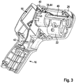
- FIG. 2 shows an opened inventive measuring device, in particular the measuring head 14 of such a measuring device, for further clarification of the mechanical, electrical and thermal structure of a possible measuring head of the measuring device according to the invention.
- an infrared sensor 32 for non-contact object temperature measurement in the housing 12 of the measuring device 10 is provided.
- the infrared temperature sensor 30 is designed as a thermopile detector for non-contact object temperature measurement. The structure and operation of such detectors are, unless already described above, known and therefore need not be further elaborated at this point.
- the infrared sensor 32 is, as well as the ambient temperature sensor 30, connected via electrical connection means 41 to a computing and evaluation unit of the measuring device 10, which is located in particular on the back of a designed as a carrier element for the infrared sensor circuit board 40.
- This printed circuit board 40 and thus also the downstream electronics of the measuring device are connected via a device-internal power supply and corresponding connection means 42 supplied with electrical energy.
- a source of energy here batteries, rechargeable batteries or battery systems can be used.
- Particularly advantageous is the use of lithium-ion batteries with standardized output voltage.
- the measuring device according to the invention can be operated, for example, with a 3.6V or 7.2V or 10.8V battery system.
- the respective energy storage medium can be permanently installed in the housing of the measuring device, in particular in the interior of the handle 16, or as in the embodiment of FIG Figures 2 and 3 be changeable.
- change batteries are particularly advantageous, which, in particular from below, can be inserted into the handle 16 of the measuring device or be removed therefrom.
- At least one further temperature sensor 34 is provided for monitoring the temperature of the infrared sensor 32 and / or its immediate surroundings.
- This further temperature sensor 34 is mounted in the immediate vicinity of the infrared sensor 32 and makes it possible to determine the temperature of the infrared sensor 32 and its immediate ambient temperature.
- the infrared sensor 32 and the other temperature sensor 34 are in the embodiment of FIG. 2 advantageously in a housing.
- this housing could be a, in FIG. 2 the sake of clarity removed tube 44, which serves as a thermal mass for the infrared sensor. In FIG. 2 only the fastening elements 43 of such a tube 44 are visible.
- Such a tube can advantageously be made of a metal, for example aluminum, and then represents a non-negligible thermal mass for stabilizing the temperature of the infrared sensor.
- FIG. 3 shows the tube 44 inserted into the measuring device with an infrared housing (IR housing) 48 and an optical marking unit 22 attached to the infrared housing 48 for visualizing the measuring range of the IR temperature measurement, ie that area whose radiation is incident on the measuring device housing and over it located IR housing and an IR lens 52 on the infrared sensor 32 passes.
- the IR housing 48 shields the IR beam path from the remaining interior of the meter housing.
- the IR housing 48 can bear frontally on the tube 44 or enclose this with a corresponding receptacle 68, as in particular in the Figures 5 and 6 is shown.
- FIG. 4 shows the arrangement of tube 44, infrared housing 48 with optical marking unit 22 and associated circuit board 40 in a detailed view, which will be discussed later.
- infrared sensor 32 and IR lens 52 will be described somewhat closer and some advantageous embodiments of the inventive measuring device will be set forth. These embodiments may themselves, i. be implemented individually in a measuring device according to the invention or else be present in different combinations.
- thermopile element 32 used in the exemplary embodiment for detecting the infrared radiation is mechanically coupled to a tube 44 in the form of an aluminum hollow cylinder, which serves as a fastening element for the thermopile 32 and other optical elements, such as a focusing lens 52 on the other hand, however, as already mentioned, represents a thermal mass to keep the ambient temperature of the thermopile detector 52 as constant as possible (see in particular also FIG. 5 . 6 and 9 ) In FIG. 9 the area B1 of the thermal contact between infrared sensor 32 and metal tube 44 is shown for clarity.
- infrared sensor 32 and metal tube 44 leads to an improvement in the accuracy of the meter in the event of temperature changes, since the tube 44 is thermally connected to the infrared sensor / thermopile 32 and thus the entire system infrared sensor / thermopile tube quickly into a thermal Balance brings.
- the IR lens 52 or a window inserted into the device instead of the lens can be made of glass, in particular a quartz glass.
- the lenses or windows it may be useful to form the lenses or windows, if appropriate also from crystals such as germanium, CaF 2, ZnS, ZnSe, KRS 5 or also polyethylene (PE) or polypropylene (PP).
- FIG. 5 and FIG. 9 show a possible arrangement of IR lens 52 and infrared sensor 32 to each other.
- the infrared sensor 32 is arranged on a printed circuit board 40 and is also in thermal contact with a tube 44, which is designed in the embodiment as an aluminum tube.
- An IR lens 52 which in the embodiment of the FIG. 5 is designed as a Fresnel lens (see also FIG. 8 , respectively.
- FIG. 9 is pressed by an elastic member 54 in the form of a foam ring 56 to the tube 44 such that the IR lens 52 is floatingly mounted between tube 44 and IR housing 48.
- the IR lens 52 By a floating support by means of foam ring 56 and an additional component (here the IR housing 48) which presses the IR lens 52 on the aluminum tube 44, on the one hand, the different thermal expansion coefficients of these components can be compensated and on the other hand, the IR lens 52 in one Be held in position.
- the IR lens 52 thus comes to lie between the tube 44 and the IR housing 48, in particular the pressure elements 58 of the IR housing.
- the positional fidelity of the IR lens 52 can still be improved by an adhesive layer, in particular on the side of the foam facing the lens 52.
- the adhesive layer is advantageously carried out as a film instead of tape, so as not to reduce the elasticity of the foam.
- an adhesive layer could be used which covers only the tube 44 and spares the lens 52 itself.
- the elastic element 54 which in the embodiments of the Figures 5 . 6 . 9 and 10 is designed as a foam ring, in alternative embodiments, directly in the pressing element, such as here the IR housing 48 or directly to the IR lens 52, in particular in one piece, are formed.
- the elastic element can be integrated directly into the other components using 2K injection molding technology.
- the pressure surfaces of the IR housing 48 on the foam of the elastic member 56 are advantageously designed as ribs, in particular star-shaped or radially extending ribs 58 to a deformation of the IR lens 52 due to different thermal expansion coefficients of IR lens and IR housing avoid.
- FIG. 7 shows the pressure surfaces for the foam element again in a detailed view of the IR housing.
- the ribs 58 are not arranged in a star shape but are oriented nearly parallel due to manufacturing requirements in injection molding manufacturing processes. However, as far as possible, the design should approximate as much as possible the star shape in order to achieve a correspondingly good decoupling.
- FIG. 7 also shows a receptacle formed in the IR housing 48 68 for the tube 44.
- the IR housing 48 in this embodiment thus encloses the infrared beam path including the metal tube 44, as in the embodiments of the Figures 5 . 6 and 10 you can see.
- FIG. 6 shows the mechanical storage of the IR lens 52 again from a different perspective.
- the IR lens 52 is, mediated by a foam ring 56, pressed by the IR housing 48 on the, mounted on the circuit board tube 44 (see also FIG. 5 and 10 ).
- it is - as in the FIGS. 6 . 9 and 10 indicated - the Fresnel structure of the IR lens 52 directed towards the sensor 32 to complicate contamination on the lens.
- the IR lens 52 has a rim or frame 60 without a structure, in particular an optical refractive structure , such as grooves or prismatic elements.
- the edge 60 is typically flat and flat and has two parallel surfaces.
- This flat part of the Fresnel lens 52 rests on the tube 44, in particular the aluminum tube. (see in particular Figures 5 . 9 and 10 ). This simultaneously improves the thermal contact of IR lens 52 and tube 44 as compared to a resting groove structure. The thermal contacting of IR lens 52 and tube 44 is in FIG. 9 in the area B2 clarified.
- the tube 44 is advantageously thermally coupled to the infrared sensor and so that the entire system IR sensor, tube, IR lens can be quickly brought into thermal equilibrium.
- vent channel 62 is provided to ensure pressure equalization between the space 70 of the tube 44 and an outdoor area and thus undesirable Deformation effect of the lens to avoid.
- the venting channel 62 may, as in FIG. 10 shown formed by a lateral bore in the tube, so that an air gap between the tube 44 and the IR housing 48 results.
- the vent channel 62 opens into one or more groove (s) 64 in the tube 44 and the infrared sensor 32 receiving circuit board 40th
- the installation space 70 between the lens 44 and infrared sensor 32 are dehumidified, which in turn prevents unwanted condensation effects on the IR lens 52 and / or formed for example as a thermopile infrared sensor 32.
- the length of the metal tube 44 can be advantageously limited to the distance IR sensor 32 to IR lens 52, wherein the above-mentioned thermal and mechanical properties of the sensor system are still ensured.
- a plastic part can be used, which serves as an IR housing 48, among other things.
- this IR housing can also accommodate or at least surround the tube 44, which acts as a thermal mass, as can be seen, for example, in US Pat Figures 3 and 10 is clarified.
- FIG. 5 and 6 each show below the actual IR housing 48 parts of a holder 66 for such an optical marking unit.
- the optical marking unit 22 is shown in structural unit with the IR housing 48.
- Such an optical Marking unit 22 can be realized in an advantageous manner by a visible laser, which is aligned with the optical axis of the infrared temperature measurement.
- An optical marking unit 22 in the form of a camera, in particular a digital camera, is also possible, as described.
- the optical marking unit can be aligned with the optical reception axis of the IR radiation.
- an elastic element for example, again a foam ring
- a spring element 72 see FIG. 1 or 2
- two screws 74 are used.
- the adjusting screws 74 are provided with a rounded end in order to ensure the most concurrent movement of the optical marking device or of the laser during the adjustment.
- An improvement in the measurement accuracy of the detection system can also be achieved by all heat sources (for example, electrically heating components) and mechanical interference sources (for example, trigger switch 20 or also a measuring mode button) can be largely decoupled from the infrared sensor 32 itself.
- heat sources for example, electrically heating components
- mechanical interference sources for example, trigger switch 20 or also a measuring mode button
- the measuring device 10 additionally has an additional temperature sensor 30 for determining the ambient temperature T u (see also FIG. 2 ).
- the ambient temperature sensor 30 is arranged in a separate extra housing 26, which is largely thermally separated from the device housing 12.
- the advantage here is the reduced interaction between the ambient temperature sensor 30 and thermal disturbances, at the same time good protection of the sensor against external influences, such as a fall or shock.
- an exposed housing part for the ambient temperature sensor is dispensed with in the present measuring device.
- PCB printed circuit board
- a printed circuit board is used for this purpose, which exceeds only slightly in geometric dimensions, the geometric dimensions of the sensor.
- the circuit board for the environmental sensor incl. Sensor is best mechanically and thermally decoupled from the main body of the meter. This is achieved by the PCB (PCB) incl. Sensor is placed in an extra housing 26 for the ambient temperature sensor, which in turn is optimally decoupled from the main housing 12 thermally by running the number of points of contact between the two housings and their overlapping surfaces as low as possible becomes.
- PCB PCB
- means 28 are provided in the measuring device according to the invention, which ensure that the extra housing 26 is thermally decoupled from the housing 12 of the device.
- the extra housing 26 for the additional ambient temperature sensor 30 can only be connected to the main housing 12 of the measuring instrument via small webs or legs 28.
- the webs 28 for attaching the extra housing 26 in the device housing 12 may be integrally connected to the extra housing 26.
- the webs or legs for attaching the extra housing 26 in the device housing 12 could be integrally connected to the device housing 12.
- the extra housing 26 of the ambient temperature sensor 30 is surrounded on at least three, in particular four sides of the device housing 12 and adapts in particular to the contour of the measuring head 14 of the measuring device according to the invention.
- the extra housing 26 is largely open in order to realize a direct exchange with the ambient air.
- the extra housing 26 is largely open in particular on its outwardly facing surface or has only a protective grid or strip structure.
- the material of the extra housing 26 is formed differently from the material of the device housing 12.
- the extra housing 26 may be formed as a metal housing.
- the extra housing 26 for the ambient temperature sensor 30 is integrated into the housing contour of the measuring housing 12 of the device, so that no protruding corners or knew in a case or shock of the meter due to their exposed position can be damaged.
- the measuring device can, for example, also measure a room and / or surface temperature, set the values in relation, interpret the data and in this way detect thermal bridges.
- the result can be displayed by LED.
- the exact measured values can be read off the display.
- the surface temperature measurement is the device internal Infrared sensor, used for room temperature measurement of the ambient temperature sensor.
- the thermodetector can also measure the humidity in addition to the room and surface temperature.
- the measuring device according to the invention also has a humidity sensor. On the basis of these three values, it is then also possible to define or detect mold-prone areas in a house. If there is an acute danger of mold, the device can warn with a red LED or, for example, acoustically. Even in this measurement mode, the exact measurement results can be read in a display.
- the measuring device measures according to the selected measuring mode, the room temperature, the surface temperature of walls and objects or the relative humidity. Temperatures are measured in particular by the method according to the invention.
- the measuring device according to the invention for non-contact measurement of object temperatures is not limited to the specific embodiments presented in the description. These show only one possibility of realizing a measuring device according to the invention.
Landscapes
- Physics & Mathematics (AREA)
- General Physics & Mathematics (AREA)
- Spectroscopy & Molecular Physics (AREA)
- Optics & Photonics (AREA)
- Radiation Pyrometers (AREA)
- Photometry And Measurement Of Optical Pulse Characteristics (AREA)
Applications Claiming Priority (1)
| Application Number | Priority Date | Filing Date | Title |
|---|---|---|---|
| DE102012215691.7A DE102012215691A1 (de) | 2012-09-05 | 2012-09-05 | Temperaturmessgerät, insbesondere handgehaltenes Infrarotmessgerät |
Publications (2)
| Publication Number | Publication Date |
|---|---|
| EP2706331A1 EP2706331A1 (de) | 2014-03-12 |
| EP2706331B1 true EP2706331B1 (de) | 2017-09-06 |
Family
ID=48782910
Family Applications (1)
| Application Number | Title | Priority Date | Filing Date |
|---|---|---|---|
| EP13175130.7A Active EP2706331B1 (de) | 2012-09-05 | 2013-07-04 | Temperaturmessgerät, insbesondere handgehaltenes Infrarotmessgerät |
Country Status (3)
| Country | Link |
|---|---|
| EP (1) | EP2706331B1 (zh) |
| CN (1) | CN103674276B (zh) |
| DE (1) | DE102012215691A1 (zh) |
Families Citing this family (8)
| Publication number | Priority date | Publication date | Assignee | Title |
|---|---|---|---|---|
| CN107192460B (zh) * | 2017-05-24 | 2023-08-29 | 浙江天铂云科光电股份有限公司 | 高散热性和防静电的单握手红外热像仪 |
| CN107328482B (zh) * | 2017-08-21 | 2023-03-31 | 优利德科技(中国)股份有限公司 | 一种用于红外测温枪的ip65结构防护装置 |
| CN110824656B (zh) * | 2018-08-07 | 2022-05-27 | 宁波舜宇车载光学技术有限公司 | 光学镜头和缓冲镜片及其制造方法 |
| CN109060142B (zh) * | 2018-08-13 | 2020-04-14 | 芜湖九鼎电子科技有限公司 | 一种可防腐蚀的两用温度检测仪 |
| CN109633667B (zh) * | 2018-12-11 | 2022-11-18 | 广州市倍尔康医疗器械有限公司 | 一种拍照、激光测距和定位辅助红外测温一体化组合结构 |
| DE102019201168A1 (de) * | 2019-01-30 | 2020-07-30 | Vitesco Technologies GmbH | Antenne für ein Hochfrequenzsystem für ein Kraftfahrzeug, Abgasbehandlungssystem sowie Verfahren zum Betreiben einer Antenne |
| CN111637973B (zh) * | 2020-05-03 | 2022-12-20 | 浙江明阳红外技术股份有限公司 | 一种用于户外的手持式红外热像仪 |
| CN111998950A (zh) * | 2020-07-08 | 2020-11-27 | 佛山市顺德区蚬华多媒体制品有限公司 | 一种额温枪 |
Citations (1)
| Publication number | Priority date | Publication date | Assignee | Title |
|---|---|---|---|---|
| US1417326A (en) * | 1921-01-18 | 1922-05-23 | Axel T Jacobsson | Lens mounting |
Family Cites Families (13)
| Publication number | Priority date | Publication date | Assignee | Title |
|---|---|---|---|---|
| US3017513A (en) * | 1959-10-08 | 1962-01-16 | Perkin Elmer Corp | Fire detection apparatus |
| US4190325A (en) * | 1977-12-02 | 1980-02-26 | Ford Motor Company | Thermal compensator assembly |
| US5323005A (en) * | 1993-05-12 | 1994-06-21 | Nordson Corporation | Method and apparatus for monitoring energy radiant from a dispensed heated material |
| JPH09113365A (ja) * | 1995-10-16 | 1997-05-02 | Matsushita Electric Ind Co Ltd | 焦電型赤外線センサ |
| JP4018782B2 (ja) * | 1997-09-10 | 2007-12-05 | シチズンホールディングス株式会社 | 放射温度計 |
| US6650412B1 (en) * | 1999-09-10 | 2003-11-18 | Kaiser Optical Systems | Thermal compensation for optical apparatus |
| US6292311B1 (en) * | 1999-10-13 | 2001-09-18 | Hewlett-Packard Company | Method and apparatus for centering a lens within an optical bore sleeve |
| US6787775B1 (en) * | 2001-07-27 | 2004-09-07 | E.D. Bullard Co. | Portable thermal imager with a shock-absorbing lens mount |
| JP2003295024A (ja) * | 2002-03-28 | 2003-10-15 | Citizen Electronics Co Ltd | 小型撮像モジュール |
| US20060198424A1 (en) * | 2005-03-02 | 2006-09-07 | Kun-Sung Chen | Probe structure for an ear thermometer |
| DE202005015397U1 (de) * | 2005-09-29 | 2007-02-08 | Testo Ag | Vorrichtung zur Bestimmung der Oberflächenfeuchte eines Messobjekts |
| JP2011090250A (ja) * | 2009-10-26 | 2011-05-06 | Canon Inc | 光学装置、それを用いた露光装置及びデバイスの製造方法 |
| CN106787775B (zh) * | 2016-12-30 | 2019-08-13 | 深圳市崧盛电子股份有限公司 | 一种双向直流转换器及其控制方法 |
-
2012
- 2012-09-05 DE DE102012215691.7A patent/DE102012215691A1/de not_active Ceased
-
2013
- 2013-07-04 EP EP13175130.7A patent/EP2706331B1/de active Active
- 2013-09-04 CN CN201310396912.0A patent/CN103674276B/zh active Active
Patent Citations (1)
| Publication number | Priority date | Publication date | Assignee | Title |
|---|---|---|---|---|
| US1417326A (en) * | 1921-01-18 | 1922-05-23 | Axel T Jacobsson | Lens mounting |
Also Published As
| Publication number | Publication date |
|---|---|
| CN103674276A (zh) | 2014-03-26 |
| DE102012215691A1 (de) | 2014-03-06 |
| CN103674276B (zh) | 2019-03-12 |
| EP2706331A1 (de) | 2014-03-12 |
Similar Documents
| Publication | Publication Date | Title |
|---|---|---|
| EP2706331B1 (de) | Temperaturmessgerät, insbesondere handgehaltenes Infrarotmessgerät | |
| EP0795121B1 (de) | Verfahren und vorrichtung zur messung von lichtbündeln | |
| DE102012215690A1 (de) | Temperaturmessgerät, sowie Verfahren zur Temperaturmessung | |
| EP2775464B1 (de) | Gefahrenmelder mit einem kontaktlos arbeitenden Wärmestrahlungssensor zur Ermittlung einer Umgebungstemperatur | |
| EP2293044B1 (de) | Vorrichtung und Verfahren zur Detektion von Verunreinigungen | |
| DE102015206038A1 (de) | Temperaturmessgerät sowie Verfahren zu dessen Betrieb | |
| EP0254879B1 (de) | Multikomponenten-Prozessanalysensystem | |
| EP0032169A1 (de) | Mit elektromagnetischer Strahlung arbeitende Meldeanlage | |
| DE102014226342A1 (de) | Wärmebildkamera | |
| US4495416A (en) | Remote sensing instrument | |
| WO1998044322A1 (de) | Messspitze für strahlungsthermometer | |
| DE4421065A1 (de) | Vorrichtung zur Temperaturmessung | |
| WO2018054671A1 (de) | Verfahren zur kontaktfreien ermittlung einer zweidimensionalen temperaturin-formation sowie infrarot-messsystem | |
| DE10229628A1 (de) | Sensoreinheit, Vorrichtung und Verfahren zur Vermeidung von Kondensation auf eine Oberfläche | |
| DE112017006565B4 (de) | Messvorrichtung für biologisches Material | |
| DE102013000751B4 (de) | Sensorvorrichtung zum Erfassen von Feuchtigkeit auf einer Scheibe | |
| DE3930828C2 (zh) | ||
| WO2016201465A2 (de) | Optischer triangulationssensor zur entfernungsmessung | |
| EP1729102B1 (en) | Detector with miniature optics for constant energy collection from different distances | |
| DE102009019572A1 (de) | Verfahren und Vorrichtung zur pyrometrischen Strahlungsmessung | |
| WO1999010716A2 (de) | Energiemessinstrument für gepulste laser | |
| DE2903328B1 (de) | Verfahren und Vorrichtung zur pyrometrischen Messung der Graphitrohrtemperatur in einner Graphitrohrkuevette | |
| DE102011108165A1 (de) | Vorrichtung für Reflexionsvermögensmessungen mit veränderbarem Winkel | |
| EP3557285B1 (de) | Laserdistanzmesser | |
| WO2009056328A1 (de) | Aktive faseroptische betauungssensorvorrichtung |
Legal Events
| Date | Code | Title | Description |
|---|---|---|---|
| PUAI | Public reference made under article 153(3) epc to a published international application that has entered the european phase |
Free format text: ORIGINAL CODE: 0009012 |
|
| AK | Designated contracting states |
Kind code of ref document: A1 Designated state(s): AL AT BE BG CH CY CZ DE DK EE ES FI FR GB GR HR HU IE IS IT LI LT LU LV MC MK MT NL NO PL PT RO RS SE SI SK SM TR |
|
| AX | Request for extension of the european patent |
Extension state: BA ME |
|
| 17P | Request for examination filed |
Effective date: 20140912 |
|
| RBV | Designated contracting states (corrected) |
Designated state(s): AL AT BE BG CH CY CZ DE DK EE ES FI FR GB GR HR HU IE IS IT LI LT LU LV MC MK MT NL NO PL PT RO RS SE SI SK SM TR |
|
| 17Q | First examination report despatched |
Effective date: 20161021 |
|
| GRAP | Despatch of communication of intention to grant a patent |
Free format text: ORIGINAL CODE: EPIDOSNIGR1 |
|
| INTG | Intention to grant announced |
Effective date: 20170324 |
|
| GRAS | Grant fee paid |
Free format text: ORIGINAL CODE: EPIDOSNIGR3 |
|
| GRAA | (expected) grant |
Free format text: ORIGINAL CODE: 0009210 |
|
| AK | Designated contracting states |
Kind code of ref document: B1 Designated state(s): AL AT BE BG CH CY CZ DE DK EE ES FI FR GB GR HR HU IE IS IT LI LT LU LV MC MK MT NL NO PL PT RO RS SE SI SK SM TR |
|
| REG | Reference to a national code |
Ref country code: GB Ref legal event code: FG4D Free format text: NOT ENGLISH |
|
| REG | Reference to a national code |
Ref country code: CH Ref legal event code: EP Ref country code: AT Ref legal event code: REF Ref document number: 926379 Country of ref document: AT Kind code of ref document: T Effective date: 20170915 |
|
| REG | Reference to a national code |
Ref country code: IE Ref legal event code: FG4D Free format text: LANGUAGE OF EP DOCUMENT: GERMAN |
|
| REG | Reference to a national code |
Ref country code: DE Ref legal event code: R096 Ref document number: 502013008255 Country of ref document: DE |
|
| REG | Reference to a national code |
Ref country code: NL Ref legal event code: MP Effective date: 20170906 |
|
| REG | Reference to a national code |
Ref country code: LT Ref legal event code: MG4D |
|
| PG25 | Lapsed in a contracting state [announced via postgrant information from national office to epo] |
Ref country code: FI Free format text: LAPSE BECAUSE OF FAILURE TO SUBMIT A TRANSLATION OF THE DESCRIPTION OR TO PAY THE FEE WITHIN THE PRESCRIBED TIME-LIMIT Effective date: 20170906 Ref country code: NO Free format text: LAPSE BECAUSE OF FAILURE TO SUBMIT A TRANSLATION OF THE DESCRIPTION OR TO PAY THE FEE WITHIN THE PRESCRIBED TIME-LIMIT Effective date: 20171206 Ref country code: HR Free format text: LAPSE BECAUSE OF FAILURE TO SUBMIT A TRANSLATION OF THE DESCRIPTION OR TO PAY THE FEE WITHIN THE PRESCRIBED TIME-LIMIT Effective date: 20170906 Ref country code: LT Free format text: LAPSE BECAUSE OF FAILURE TO SUBMIT A TRANSLATION OF THE DESCRIPTION OR TO PAY THE FEE WITHIN THE PRESCRIBED TIME-LIMIT Effective date: 20170906 Ref country code: SE Free format text: LAPSE BECAUSE OF FAILURE TO SUBMIT A TRANSLATION OF THE DESCRIPTION OR TO PAY THE FEE WITHIN THE PRESCRIBED TIME-LIMIT Effective date: 20170906 |
|
| PG25 | Lapsed in a contracting state [announced via postgrant information from national office to epo] |
Ref country code: BG Free format text: LAPSE BECAUSE OF FAILURE TO SUBMIT A TRANSLATION OF THE DESCRIPTION OR TO PAY THE FEE WITHIN THE PRESCRIBED TIME-LIMIT Effective date: 20171206 Ref country code: LV Free format text: LAPSE BECAUSE OF FAILURE TO SUBMIT A TRANSLATION OF THE DESCRIPTION OR TO PAY THE FEE WITHIN THE PRESCRIBED TIME-LIMIT Effective date: 20170906 Ref country code: ES Free format text: LAPSE BECAUSE OF FAILURE TO SUBMIT A TRANSLATION OF THE DESCRIPTION OR TO PAY THE FEE WITHIN THE PRESCRIBED TIME-LIMIT Effective date: 20170906 Ref country code: RS Free format text: LAPSE BECAUSE OF FAILURE TO SUBMIT A TRANSLATION OF THE DESCRIPTION OR TO PAY THE FEE WITHIN THE PRESCRIBED TIME-LIMIT Effective date: 20170906 Ref country code: GR Free format text: LAPSE BECAUSE OF FAILURE TO SUBMIT A TRANSLATION OF THE DESCRIPTION OR TO PAY THE FEE WITHIN THE PRESCRIBED TIME-LIMIT Effective date: 20171207 |
|
| PG25 | Lapsed in a contracting state [announced via postgrant information from national office to epo] |
Ref country code: NL Free format text: LAPSE BECAUSE OF FAILURE TO SUBMIT A TRANSLATION OF THE DESCRIPTION OR TO PAY THE FEE WITHIN THE PRESCRIBED TIME-LIMIT Effective date: 20170906 |
|
| PG25 | Lapsed in a contracting state [announced via postgrant information from national office to epo] |
Ref country code: CZ Free format text: LAPSE BECAUSE OF FAILURE TO SUBMIT A TRANSLATION OF THE DESCRIPTION OR TO PAY THE FEE WITHIN THE PRESCRIBED TIME-LIMIT Effective date: 20170906 Ref country code: RO Free format text: LAPSE BECAUSE OF FAILURE TO SUBMIT A TRANSLATION OF THE DESCRIPTION OR TO PAY THE FEE WITHIN THE PRESCRIBED TIME-LIMIT Effective date: 20170906 Ref country code: PL Free format text: LAPSE BECAUSE OF FAILURE TO SUBMIT A TRANSLATION OF THE DESCRIPTION OR TO PAY THE FEE WITHIN THE PRESCRIBED TIME-LIMIT Effective date: 20170906 |
|
| PG25 | Lapsed in a contracting state [announced via postgrant information from national office to epo] |
Ref country code: IS Free format text: LAPSE BECAUSE OF FAILURE TO SUBMIT A TRANSLATION OF THE DESCRIPTION OR TO PAY THE FEE WITHIN THE PRESCRIBED TIME-LIMIT Effective date: 20180106 Ref country code: SK Free format text: LAPSE BECAUSE OF FAILURE TO SUBMIT A TRANSLATION OF THE DESCRIPTION OR TO PAY THE FEE WITHIN THE PRESCRIBED TIME-LIMIT Effective date: 20170906 Ref country code: EE Free format text: LAPSE BECAUSE OF FAILURE TO SUBMIT A TRANSLATION OF THE DESCRIPTION OR TO PAY THE FEE WITHIN THE PRESCRIBED TIME-LIMIT Effective date: 20170906 Ref country code: SM Free format text: LAPSE BECAUSE OF FAILURE TO SUBMIT A TRANSLATION OF THE DESCRIPTION OR TO PAY THE FEE WITHIN THE PRESCRIBED TIME-LIMIT Effective date: 20170906 Ref country code: IT Free format text: LAPSE BECAUSE OF FAILURE TO SUBMIT A TRANSLATION OF THE DESCRIPTION OR TO PAY THE FEE WITHIN THE PRESCRIBED TIME-LIMIT Effective date: 20170906 |
|
| REG | Reference to a national code |
Ref country code: DE Ref legal event code: R097 Ref document number: 502013008255 Country of ref document: DE |
|
| PLBE | No opposition filed within time limit |
Free format text: ORIGINAL CODE: 0009261 |
|
| STAA | Information on the status of an ep patent application or granted ep patent |
Free format text: STATUS: NO OPPOSITION FILED WITHIN TIME LIMIT |
|
| PG25 | Lapsed in a contracting state [announced via postgrant information from national office to epo] |
Ref country code: DK Free format text: LAPSE BECAUSE OF FAILURE TO SUBMIT A TRANSLATION OF THE DESCRIPTION OR TO PAY THE FEE WITHIN THE PRESCRIBED TIME-LIMIT Effective date: 20170906 |
|
| 26N | No opposition filed |
Effective date: 20180607 |
|
| PG25 | Lapsed in a contracting state [announced via postgrant information from national office to epo] |
Ref country code: SI Free format text: LAPSE BECAUSE OF FAILURE TO SUBMIT A TRANSLATION OF THE DESCRIPTION OR TO PAY THE FEE WITHIN THE PRESCRIBED TIME-LIMIT Effective date: 20170906 |
|
| PG25 | Lapsed in a contracting state [announced via postgrant information from national office to epo] |
Ref country code: MT Free format text: LAPSE BECAUSE OF FAILURE TO SUBMIT A TRANSLATION OF THE DESCRIPTION OR TO PAY THE FEE WITHIN THE PRESCRIBED TIME-LIMIT Effective date: 20170906 |
|
| REG | Reference to a national code |
Ref country code: CH Ref legal event code: PL |
|
| GBPC | Gb: european patent ceased through non-payment of renewal fee |
Effective date: 20180704 |
|
| PG25 | Lapsed in a contracting state [announced via postgrant information from national office to epo] |
Ref country code: LU Free format text: LAPSE BECAUSE OF NON-PAYMENT OF DUE FEES Effective date: 20180704 Ref country code: MC Free format text: LAPSE BECAUSE OF FAILURE TO SUBMIT A TRANSLATION OF THE DESCRIPTION OR TO PAY THE FEE WITHIN THE PRESCRIBED TIME-LIMIT Effective date: 20170906 |
|
| REG | Reference to a national code |
Ref country code: BE Ref legal event code: MM Effective date: 20180731 |
|
| REG | Reference to a national code |
Ref country code: IE Ref legal event code: MM4A |
|
| PG25 | Lapsed in a contracting state [announced via postgrant information from national office to epo] |
Ref country code: FR Free format text: LAPSE BECAUSE OF NON-PAYMENT OF DUE FEES Effective date: 20180731 Ref country code: GB Free format text: LAPSE BECAUSE OF NON-PAYMENT OF DUE FEES Effective date: 20180704 Ref country code: LI Free format text: LAPSE BECAUSE OF NON-PAYMENT OF DUE FEES Effective date: 20180731 Ref country code: IE Free format text: LAPSE BECAUSE OF NON-PAYMENT OF DUE FEES Effective date: 20180704 Ref country code: CH Free format text: LAPSE BECAUSE OF NON-PAYMENT OF DUE FEES Effective date: 20180731 |
|
| PG25 | Lapsed in a contracting state [announced via postgrant information from national office to epo] |
Ref country code: BE Free format text: LAPSE BECAUSE OF NON-PAYMENT OF DUE FEES Effective date: 20180731 |
|
| REG | Reference to a national code |
Ref country code: AT Ref legal event code: MM01 Ref document number: 926379 Country of ref document: AT Kind code of ref document: T Effective date: 20180704 |
|
| PG25 | Lapsed in a contracting state [announced via postgrant information from national office to epo] |
Ref country code: AT Free format text: LAPSE BECAUSE OF NON-PAYMENT OF DUE FEES Effective date: 20180704 |
|
| PG25 | Lapsed in a contracting state [announced via postgrant information from national office to epo] |
Ref country code: TR Free format text: LAPSE BECAUSE OF FAILURE TO SUBMIT A TRANSLATION OF THE DESCRIPTION OR TO PAY THE FEE WITHIN THE PRESCRIBED TIME-LIMIT Effective date: 20170906 |
|
| PG25 | Lapsed in a contracting state [announced via postgrant information from national office to epo] |
Ref country code: HU Free format text: LAPSE BECAUSE OF FAILURE TO SUBMIT A TRANSLATION OF THE DESCRIPTION OR TO PAY THE FEE WITHIN THE PRESCRIBED TIME-LIMIT; INVALID AB INITIO Effective date: 20130704 Ref country code: PT Free format text: LAPSE BECAUSE OF FAILURE TO SUBMIT A TRANSLATION OF THE DESCRIPTION OR TO PAY THE FEE WITHIN THE PRESCRIBED TIME-LIMIT Effective date: 20170906 |
|
| PG25 | Lapsed in a contracting state [announced via postgrant information from national office to epo] |
Ref country code: CY Free format text: LAPSE BECAUSE OF FAILURE TO SUBMIT A TRANSLATION OF THE DESCRIPTION OR TO PAY THE FEE WITHIN THE PRESCRIBED TIME-LIMIT Effective date: 20170906 Ref country code: MK Free format text: LAPSE BECAUSE OF NON-PAYMENT OF DUE FEES Effective date: 20170906 |
|
| PG25 | Lapsed in a contracting state [announced via postgrant information from national office to epo] |
Ref country code: AL Free format text: LAPSE BECAUSE OF FAILURE TO SUBMIT A TRANSLATION OF THE DESCRIPTION OR TO PAY THE FEE WITHIN THE PRESCRIBED TIME-LIMIT Effective date: 20170906 |
|
| PGFP | Annual fee paid to national office [announced via postgrant information from national office to epo] |
Ref country code: DE Payment date: 20230922 Year of fee payment: 11 |