EP2706331B1 - Temperaturmessgerät, insbesondere handgehaltenes Infrarotmessgerät - Google Patents
Temperaturmessgerät, insbesondere handgehaltenes Infrarotmessgerät Download PDFInfo
- Publication number
- EP2706331B1 EP2706331B1 EP13175130.7A EP13175130A EP2706331B1 EP 2706331 B1 EP2706331 B1 EP 2706331B1 EP 13175130 A EP13175130 A EP 13175130A EP 2706331 B1 EP2706331 B1 EP 2706331B1
- Authority
- EP
- European Patent Office
- Prior art keywords
- measuring device
- housing
- tube
- lens
- optical element
- Prior art date
- Legal status (The legal status is an assumption and is not a legal conclusion. Google has not performed a legal analysis and makes no representation as to the accuracy of the status listed.)
- Active
Links
- 238000005259 measurement Methods 0.000 title description 14
- 230000003287 optical effect Effects 0.000 claims description 67
- 238000009529 body temperature measurement Methods 0.000 claims description 20
- 230000005855 radiation Effects 0.000 claims description 17
- 239000006260 foam Substances 0.000 claims description 16
- 229910052751 metal Inorganic materials 0.000 claims description 12
- 239000002184 metal Substances 0.000 claims description 12
- 238000007667 floating Methods 0.000 claims description 11
- 239000012790 adhesive layer Substances 0.000 claims description 7
- 238000009423 ventilation Methods 0.000 claims description 2
- 229910052782 aluminium Inorganic materials 0.000 description 7
- XAGFODPZIPBFFR-UHFFFAOYSA-N aluminium Chemical compound [Al] XAGFODPZIPBFFR-UHFFFAOYSA-N 0.000 description 7
- 239000004033 plastic Substances 0.000 description 6
- 229920003023 plastic Polymers 0.000 description 6
- 239000000463 material Substances 0.000 description 5
- 239000004698 Polyethylene Substances 0.000 description 4
- 239000004743 Polypropylene Substances 0.000 description 4
- 238000001514 detection method Methods 0.000 description 4
- 230000000694 effects Effects 0.000 description 4
- 230000006872 improvement Effects 0.000 description 4
- 238000001746 injection moulding Methods 0.000 description 4
- 238000004519 manufacturing process Methods 0.000 description 4
- -1 polyethylene Polymers 0.000 description 4
- 229920000573 polyethylene Polymers 0.000 description 4
- 229920001155 polypropylene Polymers 0.000 description 4
- XUIMIQQOPSSXEZ-UHFFFAOYSA-N Silicon Chemical compound [Si] XUIMIQQOPSSXEZ-UHFFFAOYSA-N 0.000 description 3
- 230000008859 change Effects 0.000 description 3
- 238000011156 evaluation Methods 0.000 description 3
- 229910052732 germanium Inorganic materials 0.000 description 3
- GNPVGFCGXDBREM-UHFFFAOYSA-N germanium atom Chemical compound [Ge] GNPVGFCGXDBREM-UHFFFAOYSA-N 0.000 description 3
- 229920001903 high density polyethylene Polymers 0.000 description 3
- 239000004700 high-density polyethylene Substances 0.000 description 3
- 238000009434 installation Methods 0.000 description 3
- 238000000034 method Methods 0.000 description 3
- 238000003825 pressing Methods 0.000 description 3
- 230000035939 shock Effects 0.000 description 3
- 229910052710 silicon Inorganic materials 0.000 description 3
- 239000010703 silicon Substances 0.000 description 3
- 230000006641 stabilisation Effects 0.000 description 3
- 238000011105 stabilization Methods 0.000 description 3
- 229910004261 CaF 2 Inorganic materials 0.000 description 2
- VYPSYNLAJGMNEJ-UHFFFAOYSA-N Silicium dioxide Chemical compound O=[Si]=O VYPSYNLAJGMNEJ-UHFFFAOYSA-N 0.000 description 2
- 239000000853 adhesive Substances 0.000 description 2
- 230000001070 adhesive effect Effects 0.000 description 2
- 230000008901 benefit Effects 0.000 description 2
- 238000009833 condensation Methods 0.000 description 2
- 230000005494 condensation Effects 0.000 description 2
- 239000004020 conductor Substances 0.000 description 2
- 238000011109 contamination Methods 0.000 description 2
- 239000013078 crystal Substances 0.000 description 2
- 238000013461 design Methods 0.000 description 2
- 239000011521 glass Substances 0.000 description 2
- 238000010330 laser marking Methods 0.000 description 2
- 230000000284 resting effect Effects 0.000 description 2
- SBIBMFFZSBJNJF-UHFFFAOYSA-N selenium;zinc Chemical compound [Se]=[Zn] SBIBMFFZSBJNJF-UHFFFAOYSA-N 0.000 description 2
- 229910052950 sphalerite Inorganic materials 0.000 description 2
- 238000003860 storage Methods 0.000 description 2
- PGAPATLGJSQQBU-UHFFFAOYSA-M thallium(i) bromide Chemical compound [Tl]Br PGAPATLGJSQQBU-UHFFFAOYSA-M 0.000 description 2
- 229910052984 zinc sulfide Inorganic materials 0.000 description 2
- 229910000530 Gallium indium arsenide Inorganic materials 0.000 description 1
- HBBGRARXTFLTSG-UHFFFAOYSA-N Lithium ion Chemical compound [Li+] HBBGRARXTFLTSG-UHFFFAOYSA-N 0.000 description 1
- HCHKCACWOHOZIP-UHFFFAOYSA-N Zinc Chemical compound [Zn] HCHKCACWOHOZIP-UHFFFAOYSA-N 0.000 description 1
- 238000010521 absorption reaction Methods 0.000 description 1
- 230000001154 acute effect Effects 0.000 description 1
- 238000004026 adhesive bonding Methods 0.000 description 1
- 239000003570 air Substances 0.000 description 1
- 239000012080 ambient air Substances 0.000 description 1
- 230000005540 biological transmission Effects 0.000 description 1
- 238000005352 clarification Methods 0.000 description 1
- 230000008878 coupling Effects 0.000 description 1
- 238000010168 coupling process Methods 0.000 description 1
- 238000005859 coupling reaction Methods 0.000 description 1
- 230000001419 dependent effect Effects 0.000 description 1
- 230000005670 electromagnetic radiation Effects 0.000 description 1
- 238000004146 energy storage Methods 0.000 description 1
- 238000005516 engineering process Methods 0.000 description 1
- 230000007613 environmental effect Effects 0.000 description 1
- 238000010438 heat treatment Methods 0.000 description 1
- 230000003993 interaction Effects 0.000 description 1
- 229910001416 lithium ion Inorganic materials 0.000 description 1
- 230000001404 mediated effect Effects 0.000 description 1
- 239000000203 mixture Substances 0.000 description 1
- 238000012544 monitoring process Methods 0.000 description 1
- 230000001681 protective effect Effects 0.000 description 1
- 230000009467 reduction Effects 0.000 description 1
- 238000010079 rubber tapping Methods 0.000 description 1
- 230000035945 sensitivity Effects 0.000 description 1
- 239000011359 shock absorbing material Substances 0.000 description 1
- 230000003595 spectral effect Effects 0.000 description 1
- 230000000087 stabilizing effect Effects 0.000 description 1
- 238000001931 thermography Methods 0.000 description 1
- 238000011144 upstream manufacturing Methods 0.000 description 1
- 238000013022 venting Methods 0.000 description 1
- 229910052725 zinc Inorganic materials 0.000 description 1
- 239000011701 zinc Substances 0.000 description 1
Images


Classifications
-
- G—PHYSICS
- G01—MEASURING; TESTING
- G01J—MEASUREMENT OF INTENSITY, VELOCITY, SPECTRAL CONTENT, POLARISATION, PHASE OR PULSE CHARACTERISTICS OF INFRARED, VISIBLE OR ULTRAVIOLET LIGHT; COLORIMETRY; RADIATION PYROMETRY
- G01J5/00—Radiation pyrometry, e.g. infrared or optical thermometry
-
- G—PHYSICS
- G01—MEASURING; TESTING
- G01J—MEASUREMENT OF INTENSITY, VELOCITY, SPECTRAL CONTENT, POLARISATION, PHASE OR PULSE CHARACTERISTICS OF INFRARED, VISIBLE OR ULTRAVIOLET LIGHT; COLORIMETRY; RADIATION PYROMETRY
- G01J5/00—Radiation pyrometry, e.g. infrared or optical thermometry
- G01J5/02—Constructional details
- G01J5/0205—Mechanical elements; Supports for optical elements
-
- G—PHYSICS
- G01—MEASURING; TESTING
- G01J—MEASUREMENT OF INTENSITY, VELOCITY, SPECTRAL CONTENT, POLARISATION, PHASE OR PULSE CHARACTERISTICS OF INFRARED, VISIBLE OR ULTRAVIOLET LIGHT; COLORIMETRY; RADIATION PYROMETRY
- G01J5/00—Radiation pyrometry, e.g. infrared or optical thermometry
- G01J5/02—Constructional details
- G01J5/0265—Handheld, portable
-
- G—PHYSICS
- G01—MEASURING; TESTING
- G01J—MEASUREMENT OF INTENSITY, VELOCITY, SPECTRAL CONTENT, POLARISATION, PHASE OR PULSE CHARACTERISTICS OF INFRARED, VISIBLE OR ULTRAVIOLET LIGHT; COLORIMETRY; RADIATION PYROMETRY
- G01J5/00—Radiation pyrometry, e.g. infrared or optical thermometry
- G01J5/02—Constructional details
- G01J5/028—Constructional details using a charging unit or battery
-
- G—PHYSICS
- G01—MEASURING; TESTING
- G01J—MEASUREMENT OF INTENSITY, VELOCITY, SPECTRAL CONTENT, POLARISATION, PHASE OR PULSE CHARACTERISTICS OF INFRARED, VISIBLE OR ULTRAVIOLET LIGHT; COLORIMETRY; RADIATION PYROMETRY
- G01J5/00—Radiation pyrometry, e.g. infrared or optical thermometry
- G01J5/02—Constructional details
- G01J5/04—Casings
- G01J5/046—Materials; Selection of thermal materials
-
- G—PHYSICS
- G01—MEASURING; TESTING
- G01J—MEASUREMENT OF INTENSITY, VELOCITY, SPECTRAL CONTENT, POLARISATION, PHASE OR PULSE CHARACTERISTICS OF INFRARED, VISIBLE OR ULTRAVIOLET LIGHT; COLORIMETRY; RADIATION PYROMETRY
- G01J5/00—Radiation pyrometry, e.g. infrared or optical thermometry
- G01J5/02—Constructional details
- G01J5/05—Means for preventing contamination of the components of the optical system; Means for preventing obstruction of the radiation path
-
- G—PHYSICS
- G01—MEASURING; TESTING
- G01J—MEASUREMENT OF INTENSITY, VELOCITY, SPECTRAL CONTENT, POLARISATION, PHASE OR PULSE CHARACTERISTICS OF INFRARED, VISIBLE OR ULTRAVIOLET LIGHT; COLORIMETRY; RADIATION PYROMETRY
- G01J5/00—Radiation pyrometry, e.g. infrared or optical thermometry
- G01J5/02—Constructional details
- G01J5/06—Arrangements for eliminating effects of disturbing radiation; Arrangements for compensating changes in sensitivity
- G01J5/064—Ambient temperature sensor; Housing temperature sensor; Constructional details thereof
-
- G—PHYSICS
- G01—MEASURING; TESTING
- G01J—MEASUREMENT OF INTENSITY, VELOCITY, SPECTRAL CONTENT, POLARISATION, PHASE OR PULSE CHARACTERISTICS OF INFRARED, VISIBLE OR ULTRAVIOLET LIGHT; COLORIMETRY; RADIATION PYROMETRY
- G01J5/00—Radiation pyrometry, e.g. infrared or optical thermometry
- G01J5/02—Constructional details
- G01J5/08—Optical arrangements
- G01J5/0806—Focusing or collimating elements, e.g. lenses or concave mirrors
-
- G—PHYSICS
- G02—OPTICS
- G02B—OPTICAL ELEMENTS, SYSTEMS OR APPARATUS
- G02B7/00—Mountings, adjusting means, or light-tight connections, for optical elements
- G02B7/02—Mountings, adjusting means, or light-tight connections, for optical elements for lenses
- G02B7/028—Mountings, adjusting means, or light-tight connections, for optical elements for lenses with means for compensating for changes in temperature or for controlling the temperature; thermal stabilisation
-
- G—PHYSICS
- G01—MEASURING; TESTING
- G01J—MEASUREMENT OF INTENSITY, VELOCITY, SPECTRAL CONTENT, POLARISATION, PHASE OR PULSE CHARACTERISTICS OF INFRARED, VISIBLE OR ULTRAVIOLET LIGHT; COLORIMETRY; RADIATION PYROMETRY
- G01J5/00—Radiation pyrometry, e.g. infrared or optical thermometry
- G01J5/02—Constructional details
- G01J5/06—Arrangements for eliminating effects of disturbing radiation; Arrangements for compensating changes in sensitivity
- G01J2005/065—Arrangements for eliminating effects of disturbing radiation; Arrangements for compensating changes in sensitivity by shielding
Definitions
- the invention relates to a measuring device for non-contact temperature measurement, in particular a hand-held infrared measuring device.
- Non-contact temperature measuring devices have been known for some time.
- a class of these devices is formed by the so-called infrared temperature measuring devices.
- Such measuring devices also called radiation thermometers or pyrometers, detect the heat radiation emitted by an object whose intensity and position of the emission maximum depends on its temperature. By measuring these quantities can be concluded that the temperature of the emitting object.
- thermometers which measure infrared radiation of objects by means of an IR lens and a thermopile as a detector and thus can determine their surface temperature. From the DE 20 2005 015 397 U1 Such a hand-held radiation thermometer is known. A difficulty of such measuring systems is that the components of the measuring device are in turn susceptible to temperature and, for example, have a different thermal expansion coefficient.
- the font US 6,787,778 B1 discloses a portable thermal imaging camera having a shock absorbing lens mount which minimizes the transmission of force to the lens.
- the invention has for its object to provide a measuring device for non-contact temperature measurement available, which largely avoids incorrect measurements and can ensure the most accurate measurement possible.
- the invention solves the underlying problem by means of a measuring device according to claim 1.
- the measuring device has an infrared sensor arranged in the device housing for non-contact temperature measurement.
- the infrared radiation emitted by an object to be measured such as a wall, a ceiling, a window or other objects to be examined, is concentrated in the measuring device via an optical element and directed to a sensor of the measuring device, in particular an infrared sensor.
- the infrared sensor of the device for example a thermopile detector, measures the infrared radiation which is assigned to a temperature value by an evaluation unit of the device.
- the optical element is floatingly mounted to counteract possible tension due to different temperature behavior of the components of the measuring system of the measuring device.
- the term "floating mounting” is understood here to mean the mobility of the element, in the present example the mobility of the optical element, in at least one direction or one plane.
- the optical element can be pressed in the axial direction in order to assume a defined axial position, which, for example, corresponds to a focal length of a lens, but to be mounted without force in the radial direction. It is also possible, alternatively or additionally, to apply a force to the optical element in the axial direction only indirectly, in order to obtain mobility for the element in this direction as well. This can be achieved in particular by means of an elastic mounting.
- the different coefficients of thermal expansion of the optical element and its holder, so for example a lens and corresponding lens holder, bill taken can be compensated for by, for example, an elastic element and, on the other hand, the optical element, such as, for example, a lens, be held in a defined position, for example the focal length.
- HDPE High Density Polyethylene
- the position of the lens and thus the measuring range on the examination object relative to a reference in the measuring device is not uniquely determined and is changing, especially over the product lifetime.
- the inventive design of the measuring system of a measuring device for non-contact temperature measurement, in particular a hand-held infrared measuring device eliminates these disadvantages of the prior art.
- the position of the optical element can be maintained defined for a longer period of time and on the other hand, the different thermal expansion coefficient of the measuring system, in particular the optical element and its holder, so for example a lens and corresponding lens holder, Be taken into account.
- wavelength range is optimal for the desired measurement depends in principle on the material to be measured and its temperature. For temperatures around room temperature, which represent a typical range of use of the measuring device according to the invention, wavelengths in the middle infrared come into question.
- thermopile thermopile
- photoelectric detectors can also be used.
- Temperatures above approx. 350 ° C can be determined in the near infrared with IR photodiodes.
- a germanium photodiode has a maximum receive wavelength of about 1.9 microns.
- the more suitable material InGaAs can be manufactured depending on the composition for maximum reception wavelengths from 1.9 to 2.6 ⁇ m
- Temperatures from about 700 ° C can be measured with silicon photodiodes (maximum reception wavelength about 0.9 to 1.1 microns) or with comparison methods in the visible spectral range. At the maximum receive wavelength of silicon photodiodes (1.1 ⁇ m), a body with a temperature of 3000 K has its radiation maximum, but with silicon photodiodes all temperatures above about 700 ° C can be measured.
- the temperature measuring range of a pyrometer upwards is much easier to expand than down, because with increasing temperature, the radiation power increases at all wavelengths.
- IR infrared
- the dependent claims give advantageous and / or preferred embodiments of the measuring device according to the invention again.
- the optical element of the claimed measuring device is mounted between a tube receiving the infrared sensor, in particular a metal tube, and an IR housing enclosing the infrared beam path.
- an IR housing is understood to be a housing, in particular a plastic housing, which surrounds the infrared beam path in the measuring device and shields it from other components of the measuring device interior.
- the IR housing can contain the IR sensor, an IR lens and other elements of the measuring system.
- the IR housing is in turn stored floating in the device housing of the measuring device.
- a tube made of metal, for example aluminum or zinc can be used in an advantageous manner, which ensures by its high thermal conductivity for a thermal equilibrium and with its heat capacity, the measuring system make robust against rapid temperature changes.
- the infrared sensor is mechanically and thermally coupled to the metal tube, its thermal mass can be used to keep the temperature of the IR sensor as constant as possible.
- the tube may be arranged in or on the IR housing such that the IR housing presses the optical element against the tube.
- the direct contact of tube and optical element also leads to a thermal stabilization of the optical element.
- the optical element is pressed by means of an elastic element against the tube, so that the position, in particular an axial position of the optical element is defined, a certain mobility of the element - for example due to a significant change in temperature - but given.
- the elastic element may be, for example, a foam element, in particular a foam ring, which ensures a floating mounting of the optical element, but holds the optical element in its particular axial position.
- the elastic element would be, for example, in particular resilient, pressure elements for the optical element, which ensure its floating storage.
- an adhesive layer is provided on the side of the elastic element facing the optical element.
- the positional fidelity of the optical element can still be improved by such an adhesive layer on the lens-facing foam side of the elastic element, which is advantageously designed as a film instead of tape, in order not to reduce the elasticity of the foam.
- an adhesive layer can be used, which covers only the tube and the lens itself but spared.
- the elastic element can also be integrated directly in the pressing element (IR housing) or directly in the optical element, for example by a 2K injection molding technique.
- the pressure surfaces or pressing elements of the IR housing on the foam of the elastic element are advantageously designed as star-shaped ribs in order to avoid deformation of the optical element due to different thermal expansion coefficients of the optical element and IR housing.
- the optical element itself is formed in an advantageous embodiment as a lens or IR lens, advantageously also in particular as a Fresnel lens.
- the lens may consist of glass, in particular a quartz glass.
- crystals such as germanium, CaF 2, ZnS, ZnSe, KRS 5 or else polyethylene (PE) or polypropylene (PP).
- DOE diffractive element
- the Fresnel structure of the optical element formed as a lens can be formed on both sides or advantageously only on one side of the - in particular substantially planar - optical element.
- the Fresnel structure will then be directed towards the sensor to impede contamination on the lens.
- the IR lens advantageously has a rim without a Fresnel structure. With this edge or frame this is on the tube, in particular an aluminum tube on.
- the direct and surface contact of the IR lens with the tube, in particular a metal tube at the same time improves the thermal contact from lens to tube compared to a resting groove structure.
- the direct contact of tube and optical element advantageously also leads to a thermal stabilization of the optical element.
- the system (tube, IR lens, infrared sensor) is well sealed, so advantageously a vent channel can be provided in the arrangement to ensure pressure equalization, in particular of the interior of the tube, and thus undesirable Deformation effect of the lens to avoid by especially thermally induced pressure changes.
- the installation space between the lens and the infrared sensor can be dehumidified via such a ventilation channel, which in turn prevents undesirable condensation effects on the IR lens or the thermopile detector.
- FIG. 1 shows an inventive measuring device 10 for non-contact temperature measurement in a perspective overview.
- the measuring device 10 of FIG. 1 is designed as a hand-held infrared measuring device with infrared sensor.
- the measuring device 10 has a device housing 12 with a measuring head 14, and a grip area 16 for operating the measuring device in a hand-held manner.
- a measuring switch 20 is formed, with which, inter alia, a temperature measurement can be started with the device.
- an optically visible signal for example a laser marking, which indicates to a user
- the measuring device according to the invention has an optical marking unit 22, which is aligned with the field of view of the thermo-detector of the measuring device.
- the optical marking unit 22 may generate a single measurement point that defines the center of the infrared measurement. It is advantageous if the optical marking unit marks the area of the infrared measurement by indicating it within its limits.
- a diffractive element 78 can be used, which surrounds the area which is used for temperature measurement, in particular circularly with a corresponding laser marking.
- the optical marking unit 22 may alternatively or additionally also include a camera, in particular a digital camera.
- a camera in particular a digital camera.
- the camera in particular a digital camera, records the extended measuring range of the surface temperature measurement.
- this camera image which can be played back on a display of the meter, then the example, computationally determined exact location of the temperature measurement can be displayed to visualize a user, at which point exactly the surface temperature is measured.
- infrared sensor 32 is arranged (see in particular also FIG. 2 . 9 and 10 ), which detects the emitted by a measuring object and focused on a lens element IR radiation for temperature determination.
- thermopile detector or a photosensor, such as a photodiode can be used.
- thermopile detector or thermopile is a detector for electromagnetic radiation in a wide wavelength range, which is based on the absorption of the radiation and the measurement of the resulting heat flow along a heat conductor.
- the basic component of such a thermopile is a thermocouple, blackened and irradiated one joint, the other is protected from irradiation. Usually several such elements are connected in series, so that the irradiated areas form an area. In this case, the thermocouples themselves form the heat conductor.
- the measuring device has a computing and evaluation unit in order to convert the detection signal into a temperature value.
- the determined temperature value can be represented by means of an output unit, in particular a display 18, which is arranged on the side of the device housing 12 facing away from the measuring direction.
- a temperature value can be output or relative temperature conditions, color-coded, can be displayed.
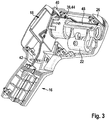
- FIG. 2 shows an opened inventive measuring device, in particular the measuring head 14 of such a measuring device, for further clarification of the mechanical, electrical and thermal structure of a possible measuring head of the measuring device according to the invention.
- an infrared sensor 32 for non-contact object temperature measurement in the housing 12 of the measuring device 10 is provided.
- the infrared temperature sensor 30 is designed as a thermopile detector for non-contact object temperature measurement. The structure and operation of such detectors are, unless already described above, known and therefore need not be further elaborated at this point.
- the infrared sensor 32 is, as well as the ambient temperature sensor 30, connected via electrical connection means 41 to a computing and evaluation unit of the measuring device 10, which is located in particular on the back of a designed as a carrier element for the infrared sensor circuit board 40.
- This printed circuit board 40 and thus also the downstream electronics of the measuring device are connected via a device-internal power supply and corresponding connection means 42 supplied with electrical energy.
- a source of energy here batteries, rechargeable batteries or battery systems can be used.
- Particularly advantageous is the use of lithium-ion batteries with standardized output voltage.
- the measuring device according to the invention can be operated, for example, with a 3.6V or 7.2V or 10.8V battery system.
- the respective energy storage medium can be permanently installed in the housing of the measuring device, in particular in the interior of the handle 16, or as in the embodiment of FIG Figures 2 and 3 be changeable.
- change batteries are particularly advantageous, which, in particular from below, can be inserted into the handle 16 of the measuring device or be removed therefrom.
- At least one further temperature sensor 34 is provided for monitoring the temperature of the infrared sensor 32 and / or its immediate surroundings.
- This further temperature sensor 34 is mounted in the immediate vicinity of the infrared sensor 32 and makes it possible to determine the temperature of the infrared sensor 32 and its immediate ambient temperature.
- the infrared sensor 32 and the other temperature sensor 34 are in the embodiment of FIG. 2 advantageously in a housing.
- this housing could be a, in FIG. 2 the sake of clarity removed tube 44, which serves as a thermal mass for the infrared sensor. In FIG. 2 only the fastening elements 43 of such a tube 44 are visible.
- Such a tube can advantageously be made of a metal, for example aluminum, and then represents a non-negligible thermal mass for stabilizing the temperature of the infrared sensor.
- FIG. 3 shows the tube 44 inserted into the measuring device with an infrared housing (IR housing) 48 and an optical marking unit 22 attached to the infrared housing 48 for visualizing the measuring range of the IR temperature measurement, ie that area whose radiation is incident on the measuring device housing and over it located IR housing and an IR lens 52 on the infrared sensor 32 passes.
- the IR housing 48 shields the IR beam path from the remaining interior of the meter housing.
- the IR housing 48 can bear frontally on the tube 44 or enclose this with a corresponding receptacle 68, as in particular in the Figures 5 and 6 is shown.
- FIG. 4 shows the arrangement of tube 44, infrared housing 48 with optical marking unit 22 and associated circuit board 40 in a detailed view, which will be discussed later.
- infrared sensor 32 and IR lens 52 will be described somewhat closer and some advantageous embodiments of the inventive measuring device will be set forth. These embodiments may themselves, i. be implemented individually in a measuring device according to the invention or else be present in different combinations.
- thermopile element 32 used in the exemplary embodiment for detecting the infrared radiation is mechanically coupled to a tube 44 in the form of an aluminum hollow cylinder, which serves as a fastening element for the thermopile 32 and other optical elements, such as a focusing lens 52 on the other hand, however, as already mentioned, represents a thermal mass to keep the ambient temperature of the thermopile detector 52 as constant as possible (see in particular also FIG. 5 . 6 and 9 ) In FIG. 9 the area B1 of the thermal contact between infrared sensor 32 and metal tube 44 is shown for clarity.
- infrared sensor 32 and metal tube 44 leads to an improvement in the accuracy of the meter in the event of temperature changes, since the tube 44 is thermally connected to the infrared sensor / thermopile 32 and thus the entire system infrared sensor / thermopile tube quickly into a thermal Balance brings.
- the IR lens 52 or a window inserted into the device instead of the lens can be made of glass, in particular a quartz glass.
- the lenses or windows it may be useful to form the lenses or windows, if appropriate also from crystals such as germanium, CaF 2, ZnS, ZnSe, KRS 5 or also polyethylene (PE) or polypropylene (PP).
- FIG. 5 and FIG. 9 show a possible arrangement of IR lens 52 and infrared sensor 32 to each other.
- the infrared sensor 32 is arranged on a printed circuit board 40 and is also in thermal contact with a tube 44, which is designed in the embodiment as an aluminum tube.
- An IR lens 52 which in the embodiment of the FIG. 5 is designed as a Fresnel lens (see also FIG. 8 , respectively.
- FIG. 9 is pressed by an elastic member 54 in the form of a foam ring 56 to the tube 44 such that the IR lens 52 is floatingly mounted between tube 44 and IR housing 48.
- the IR lens 52 By a floating support by means of foam ring 56 and an additional component (here the IR housing 48) which presses the IR lens 52 on the aluminum tube 44, on the one hand, the different thermal expansion coefficients of these components can be compensated and on the other hand, the IR lens 52 in one Be held in position.
- the IR lens 52 thus comes to lie between the tube 44 and the IR housing 48, in particular the pressure elements 58 of the IR housing.
- the positional fidelity of the IR lens 52 can still be improved by an adhesive layer, in particular on the side of the foam facing the lens 52.
- the adhesive layer is advantageously carried out as a film instead of tape, so as not to reduce the elasticity of the foam.
- an adhesive layer could be used which covers only the tube 44 and spares the lens 52 itself.
- the elastic element 54 which in the embodiments of the Figures 5 . 6 . 9 and 10 is designed as a foam ring, in alternative embodiments, directly in the pressing element, such as here the IR housing 48 or directly to the IR lens 52, in particular in one piece, are formed.
- the elastic element can be integrated directly into the other components using 2K injection molding technology.
- the pressure surfaces of the IR housing 48 on the foam of the elastic member 56 are advantageously designed as ribs, in particular star-shaped or radially extending ribs 58 to a deformation of the IR lens 52 due to different thermal expansion coefficients of IR lens and IR housing avoid.
- FIG. 7 shows the pressure surfaces for the foam element again in a detailed view of the IR housing.
- the ribs 58 are not arranged in a star shape but are oriented nearly parallel due to manufacturing requirements in injection molding manufacturing processes. However, as far as possible, the design should approximate as much as possible the star shape in order to achieve a correspondingly good decoupling.
- FIG. 7 also shows a receptacle formed in the IR housing 48 68 for the tube 44.
- the IR housing 48 in this embodiment thus encloses the infrared beam path including the metal tube 44, as in the embodiments of the Figures 5 . 6 and 10 you can see.
- FIG. 6 shows the mechanical storage of the IR lens 52 again from a different perspective.
- the IR lens 52 is, mediated by a foam ring 56, pressed by the IR housing 48 on the, mounted on the circuit board tube 44 (see also FIG. 5 and 10 ).
- it is - as in the FIGS. 6 . 9 and 10 indicated - the Fresnel structure of the IR lens 52 directed towards the sensor 32 to complicate contamination on the lens.
- the IR lens 52 has a rim or frame 60 without a structure, in particular an optical refractive structure , such as grooves or prismatic elements.
- the edge 60 is typically flat and flat and has two parallel surfaces.
- This flat part of the Fresnel lens 52 rests on the tube 44, in particular the aluminum tube. (see in particular Figures 5 . 9 and 10 ). This simultaneously improves the thermal contact of IR lens 52 and tube 44 as compared to a resting groove structure. The thermal contacting of IR lens 52 and tube 44 is in FIG. 9 in the area B2 clarified.
- the tube 44 is advantageously thermally coupled to the infrared sensor and so that the entire system IR sensor, tube, IR lens can be quickly brought into thermal equilibrium.
- vent channel 62 is provided to ensure pressure equalization between the space 70 of the tube 44 and an outdoor area and thus undesirable Deformation effect of the lens to avoid.
- the venting channel 62 may, as in FIG. 10 shown formed by a lateral bore in the tube, so that an air gap between the tube 44 and the IR housing 48 results.
- the vent channel 62 opens into one or more groove (s) 64 in the tube 44 and the infrared sensor 32 receiving circuit board 40th
- the installation space 70 between the lens 44 and infrared sensor 32 are dehumidified, which in turn prevents unwanted condensation effects on the IR lens 52 and / or formed for example as a thermopile infrared sensor 32.
- the length of the metal tube 44 can be advantageously limited to the distance IR sensor 32 to IR lens 52, wherein the above-mentioned thermal and mechanical properties of the sensor system are still ensured.
- a plastic part can be used, which serves as an IR housing 48, among other things.
- this IR housing can also accommodate or at least surround the tube 44, which acts as a thermal mass, as can be seen, for example, in US Pat Figures 3 and 10 is clarified.
- FIG. 5 and 6 each show below the actual IR housing 48 parts of a holder 66 for such an optical marking unit.
- the optical marking unit 22 is shown in structural unit with the IR housing 48.
- Such an optical Marking unit 22 can be realized in an advantageous manner by a visible laser, which is aligned with the optical axis of the infrared temperature measurement.
- An optical marking unit 22 in the form of a camera, in particular a digital camera, is also possible, as described.
- the optical marking unit can be aligned with the optical reception axis of the IR radiation.
- an elastic element for example, again a foam ring
- a spring element 72 see FIG. 1 or 2
- two screws 74 are used.
- the adjusting screws 74 are provided with a rounded end in order to ensure the most concurrent movement of the optical marking device or of the laser during the adjustment.
- An improvement in the measurement accuracy of the detection system can also be achieved by all heat sources (for example, electrically heating components) and mechanical interference sources (for example, trigger switch 20 or also a measuring mode button) can be largely decoupled from the infrared sensor 32 itself.
- heat sources for example, electrically heating components
- mechanical interference sources for example, trigger switch 20 or also a measuring mode button
- the measuring device 10 additionally has an additional temperature sensor 30 for determining the ambient temperature T u (see also FIG. 2 ).
- the ambient temperature sensor 30 is arranged in a separate extra housing 26, which is largely thermally separated from the device housing 12.
- the advantage here is the reduced interaction between the ambient temperature sensor 30 and thermal disturbances, at the same time good protection of the sensor against external influences, such as a fall or shock.
- an exposed housing part for the ambient temperature sensor is dispensed with in the present measuring device.
- PCB printed circuit board
- a printed circuit board is used for this purpose, which exceeds only slightly in geometric dimensions, the geometric dimensions of the sensor.
- the circuit board for the environmental sensor incl. Sensor is best mechanically and thermally decoupled from the main body of the meter. This is achieved by the PCB (PCB) incl. Sensor is placed in an extra housing 26 for the ambient temperature sensor, which in turn is optimally decoupled from the main housing 12 thermally by running the number of points of contact between the two housings and their overlapping surfaces as low as possible becomes.
- PCB PCB
- means 28 are provided in the measuring device according to the invention, which ensure that the extra housing 26 is thermally decoupled from the housing 12 of the device.
- the extra housing 26 for the additional ambient temperature sensor 30 can only be connected to the main housing 12 of the measuring instrument via small webs or legs 28.
- the webs 28 for attaching the extra housing 26 in the device housing 12 may be integrally connected to the extra housing 26.
- the webs or legs for attaching the extra housing 26 in the device housing 12 could be integrally connected to the device housing 12.
- the extra housing 26 of the ambient temperature sensor 30 is surrounded on at least three, in particular four sides of the device housing 12 and adapts in particular to the contour of the measuring head 14 of the measuring device according to the invention.
- the extra housing 26 is largely open in order to realize a direct exchange with the ambient air.
- the extra housing 26 is largely open in particular on its outwardly facing surface or has only a protective grid or strip structure.
- the material of the extra housing 26 is formed differently from the material of the device housing 12.
- the extra housing 26 may be formed as a metal housing.
- the extra housing 26 for the ambient temperature sensor 30 is integrated into the housing contour of the measuring housing 12 of the device, so that no protruding corners or knew in a case or shock of the meter due to their exposed position can be damaged.
- the measuring device can, for example, also measure a room and / or surface temperature, set the values in relation, interpret the data and in this way detect thermal bridges.
- the result can be displayed by LED.
- the exact measured values can be read off the display.
- the surface temperature measurement is the device internal Infrared sensor, used for room temperature measurement of the ambient temperature sensor.
- the thermodetector can also measure the humidity in addition to the room and surface temperature.
- the measuring device according to the invention also has a humidity sensor. On the basis of these three values, it is then also possible to define or detect mold-prone areas in a house. If there is an acute danger of mold, the device can warn with a red LED or, for example, acoustically. Even in this measurement mode, the exact measurement results can be read in a display.
- the measuring device measures according to the selected measuring mode, the room temperature, the surface temperature of walls and objects or the relative humidity. Temperatures are measured in particular by the method according to the invention.
- the measuring device according to the invention for non-contact measurement of object temperatures is not limited to the specific embodiments presented in the description. These show only one possibility of realizing a measuring device according to the invention.
Description
- Die Erfindung betrifft ein Messgerät zur berührungslosen Temperaturmessung, insbesondere ein handgehaltenes Infrarotmessgerät.
- Berührungslose Temperaturmessgeräte sind seit längerer Zeit bekannt. Eine Klasse dieser Geräte wird gebildet durch die sogenannten Infrarottemperaturmessgeräte. Derartige Messgeräte, auch Strahlungsthermometer oder Pyrometer genannt, detektieren die von einem Objekt emittierte Wärmestrahlung, deren Intensität und Lage des Emissionsmaximums von seiner Temperatur abhängt. Durch eine Messung dieser Größen kann auf die Temperatur des emittierenden Objektes geschlossen werden.
- Bekannt sind Pyrometer die mittels einer IR-Linse und einem Thermopile als Detektor Infrarotstrahlung von Objekten messen und somit deren Oberflächentemperatur bestimmen können. Aus der
DE 20 2005 015 397 U1 ist ein derartiges handgehaltenes Strahlungsthermometer bekannt. Eine Schwierigkeit solcher Messsysteme liegt darin, dass die Komponenten des Messgerätes wiederum temperaturanfällig sind und beispielsweise einen unterschiedlichen Wärmeausdehnungskoeffizienten aufweisen. - Die Schrift
US 6,787,778 B1 offenbart eine tragbare Wärmebildkamera, die eine stoßabsorbierende Linsenbefestigung aufweist, die die Übertragung von Krafteinwirkungen auf die Linse minimiert. - Ähnlich wird in
US 3,017,513 ein Infrarot-Feuerdetektionsapparat vorgestellt, der einen Parabolspiegel aufweist, der mittels eines stoßabsorbierenden Materials, beispielsweise Gummi oder Plastik, getragen wird. - Der Erfindung liegt die Aufgabe zugrunde, ein Messgerät zur berührungslosen Temperaturmessung zur Verfügung zu stellen, welches Fehlmessungen weitgehend vermeidet und eine möglichst genaue Messung gewährleisten kann.
- Die Erfindung löst das zugrundeliegende Problem mittels eines Messgerätes nach Anspruch 1.
- Das erfindungsgemäße Messgerät weist einen im Gerätegehäuse angeordneten Infrarotsensor zur berührungslosen Temperaturmessung auf. Die von einem zu vermessenden Objekt, wie beispielsweise einer Wand, einer Decke, einem Fenster oder einem anderen Untersuchungsgegenständen entsprechend seiner Temperatur abgestrahlte Infrarotstrahlung wird über ein optisches Element im Messgerät gebündelt und auf einen Sensor des Messgerätes, insbesondere einen Infrarotsensor gelenkt. Der Infrarotsensor des Gerätes, beispielsweise ein Thermopile-Detektor misst die Infrarotstrahlung, die von einer Auswerteeinheit des Gerätes einem Temperaturwert zugeordnet. Erfindungsgemäß ist das optische Element dabei schwimmend gelagert, um möglichen Verspannungen aufgrund unterschiedlichen Temperaturverhaltens der Komponenten des Messsystems des Messgerätes entgegen zu wirken.
- Unter einer schwimmenden Lagerung soll hierbei die Bewegbarkeit des Elementes, im vorliegenden Beispiel die Bewegbarkeit des optischen Elementes, in zumindest einer Richtung bzw. einer Ebene verstanden werden. So kann das optische Element beispielsweise in axialer Richtung angedrückt werden, um eine definierte axiale Position, die beispielsweise einer Brennweite einer Linse entspricht, einzunehmen, in radialer Richtung aber kraftfrei gelagert sein. Auch ist es möglich, alternativ oder zusätzlich, auf das optische Element in axialer Richtung auch nur mittelbar eine Kraft anzuwenden, um dem Element auch in dieser Richtung eine Beweglichkeit zu erhalten. Dies ist insbesondere durch eine elastische Lagerung realisierbar.
- Durch eine schwimmende Lagerung kann einerseits der unterschiedlichen Wärmeausdehnungskoeffizienten des optischen Elementes und dessen Halterung, also beispielsweise einer Linse und entsprechender Linsenhalterung, Rechnung getragen werden, indem diese beispielsweise durch ein elastisches Element kompensiert werden und andererseits das optische Element, wie beispielsweise eine Linse in einer definierten Position, beispielsweise der Brennweite, gehalten werden.
- Mit der schwimmenden Lagerung kann das Problem der inneren Verspannung des gelagerten Elementes vermieden werden, wenn eine axiale oder radiale Beweglichkeit für die Funktion des Aggregats nicht schädlich ist.
- Bei auf dem Markt befindlichen Messgeräten werden derzeit HDPE (High Density Polyethylen) Linsen als optisches Infrarotelement verwendet, die mit Spiel in einem Linsenhalter eingebaut sind, um den unterschiedlichen Wärmeausdehnungskoeffizienten von Linsenhalter und HDPE-Linse zu berücksichtigen. Ein Verkleben ist auf Grund der mangelnden Flexibilität, der unzureichenden Haftbarkeit von UV-Klebern und der Ausgaseigenschaften von herkömmlichen Klebern nicht möglich bzw. nicht sinnvoll.
- Durch eine derartige Anordnung der IR-Linse, wie sie aus dem Stand der Technik bekannt ist, ist die Position der Linse und damit der Messbereich auf dem Untersuchungsobjekt bezogen zu einer Referenz im Messgerät, wie beispielsweise einer optischen Markierungseinheit (z.B. Laser) nicht eindeutig bestimmt und ändert sich, insbesondere über die Produktlebenszeit.
- Die erfindungsgemäße Ausbildung des Messsystems eines Messgerät zur berührungslosen Temperaturmessung, insbesondere eines handgehaltenes Infrarotmessgerät behebt diese Nachteile des Standes der Technik. Durch eine schwimmende Lagerung des optischen IR-Elementes eines Infrarottemperaturmessgerätes kann einerseits die Position des optischen Elementes auch für einen längeren Zeitraum definiert beibehalten werden und andererseits der unterschiedlichen Wärmeausdehnungskoeffizienten des Messsystems, insbesondere des optischen Elementes und dessen Halterung, also beispielsweise einer Linse und entsprechender Linsenhalterung, Rechnung getragen werden.
- Welche Wellenlängenbereich für die gewünschte Messung optimal ist, hängt prinzipiell vom zu messenden Material und seiner Temperatur ab. Für Temperaturen um die Raumtemperatur, welche einen typischen Verwendungsbereich des erfindungsgemäßen Messgerätes darstellen, kommen Wellenlängen im Mittleren Infrarot in Frage.
- Es können hierbei thermische, insbesondere pyroelektrische Sensoren, wie beispielsweise Thermosäulen (=Thermopile) zum Einsatz kommen. Bei höheren Temperaturen können auch photoelektrische Detektoren verwendet werden.
- Temperaturen ab ca. 350 °C können im Nahen Infrarot mit IR-Fotodioden bestimmt werden. So hat eine Germanium-Fotodiode z.B. eine maximale Empfangswellenlänge von etwa 1,9 µm. Das besser geeignete Material InGaAs kann je nach Zusammensetzung für maximale Empfangswellenlängen von 1,9 bis 2,6 µm gefertigt werden
- Temperaturen ab etwa 700 °C können mit Silicium-Fotodioden (maximale Empfangswellenlänge etwa 0,9 bis 1,1 µm) oder auch mit Vergleichsverfahren im sichtbaren Spektralbereich gemessen werden. Bei der maximalen Empfangswellenlänge von Silicium-Fotodioden (1,1 µm) hat ein Körper mit einer Temperatur von 3000 K sein Strahlungsmaximum, mit Silicium Fotodioden können jedoch alle Temperaturen oberhalb etwa 700 °C gemessen werden.
- Generell ist der Temperaturmessbereich eines Pyrometers nach oben deutlich einfacher zu erweitern als nach unten, da mit steigender Temperatur die Strahlungsleistung bei allen Wellenlängen ansteigt.
- Alle diese Wellenlängen werden im Rahmen der vorliegenden Schrift als Infrarot (IR) bezeichnet.
- Die abhängigen Ansprüche geben vorteilhafte und/oder bevorzugte Ausführungsformen des erfindungsgemäßen Messgerätes wieder. Das optische Element des beanspruchten Messgerätes ist zwischen einem den Infrarotsensor aufnehmenden Tubus, insbesondere einen Metalltubus, und einem, den Infrarotstrahlengang umgreifendes IR-Gehäuse gelagert.
- Als IR-Gehäuse wird im Rahmen dieser Anmeldung ein Gehäuse, insbesondere ein Kunststoffgehäuse verstanden, welches den Infrarotstrahlengang im Messgerät umgibt und gegenüber weiteren Komponenten des Messgeräteinnenraums abschirmt. Im IR-Gehäuse können sich insbesondere der IR-Sensor, eine IR Linse und weitere Elementes des Messsystems befinden. Das IR-Gehäuse ist in vorteilhafter Weise wiederum schwimmend im Gerätegehäuse des Messgerätes gelagert. Als Halter bzw. Anschlagelement sowohl des optischen Elementes als auch des Infrarotsensors des erfindungsgemäßen Messsystems kann in vorteilhafter Weise ein Tubus aus Metall, beispielsweise aus Aluminium oder Zink eingesetzt werden, der durch seine hohe thermische Leitfähigkeit für ein thermisches Gleichgewicht sorgt und mit seiner Wärmekapazität das Messsystem robust gegen schnelle Temperaturänderungen machen.
- Ist der Infrarotsensor mechanisch und thermisch an den Metalltubus angekoppelt, so kann dessen thermische Masse genutzt werden, die Temperatur des IR-Sensors möglichst konstant zu halten.
- In vorteilhafter Weise kann der Tubus derart im oder am IR-Gehäuse angeordnet sein, dass das IR-Gehäuse das optische Element an den Tubus andrückt. Der direkte Kontakt von Tubus und optischem Element führt dabei ebenfalls zu einer thermischen Stabilisierung des optischen Elementes.
- In vorteilhafter Weise wird das optische Element mittels eines elastischen Elementes gegen den Tubus gedrückt, so dass die Position, insbesondere eine axiale Position des optischen Elementes definiert ist, eine gewisse Beweglichkeit des Elementes - beispielsweise aufgrund einer deutlichen Temperaturänderung - aber gegeben wäre.
- Das elastische Element kann dabei beispielsweise ein Schaumstoffelement, insbesondere ein Schaumstoffring, sein, das eine schwimmende Lagerung des optischen Elementes gewährleistet, das optische Element aber in seiner insbesondere axialen Position hält.
- Alternative Ausführungsformen des elastischen Elementes wären beispielsweise, insbesondere federnde, Andruckelemente für das optische Element, welche dessen schwimmende Lagerung gewährleisten.
- In einer Ausführungsform kann vorgesehen sein, dass eine Klebeschicht auf der zum optischen Element gewandten Seite des elastischen Elementes vorgesehen ist. Die Positionstreue des optischen Elementes kann durch eine solche Klebeschicht auf der zur Linse gewandte Schaumstoffseite des elastischen Elementes, die vorteilhafterweise als Film statt als Tape ausgeführt wird, um die Elastizität des Schaumstoffs nicht zu verringern, noch verbessert werden.
- Alternativ kann auch eine Klebeschicht verwendet werden, die nur den Tubus bedeckt und die Linse selbst aber ausspart.
- In alternativen Ausführungsformen oder zusätzlich kann das elastische Element auch direkt im andrückenden Element (IR-Gehäuse) oder direkt in das optische Element, beispielsweise durch ein 2K-Spritzgusstechnik, integriert werden.
- Die Andruckflächen bzw. Andruckelemente des IR-Gehäuses auf den Schaumstoff des elastischen Elementes werden vorteilhafterweise als sternförmige Rippen ausgeführt, um eine Verformung des optischen Elementes auf Grund von unterschiedlichen Wärmeausdehnungskoeffizienten von optischem Element und IR-Gehäuse zu vermeiden.
- Auf Grund von Beschränkungen beim Herstellungsverfahren des insbesondere in Kunststoff ausgebildeten IR-Gehäuse - hier könnte ein Spritzgussverfahren Verwendung finden - könnte von einer sternförmigen Anordnung der Andruckflächen bzw. Andruckelemente des IR-Gehäuses auch abgewichen werden, allerdings sollte auch dann die Ausführungsform so gut wie möglich der Sternform angenähert ein. Parallele Andruckelemente wären ebenso möglich.
- Das optische Element selbst ist in einer vorteilhaften Ausführungsform als Linse bzw. IR-Linse, vorteilhafter Weise insbesondere auch als Fresnel-Linse, ausgebildet. Die Linse kann aus Glas, insbesondere einem Quarzglas bestehen. Für den mittleren IR-Bereich ist es gegebenenfalls sinnvoll, die Linsen gegebenenfalls auch aus Kristallen wie Germanium, CaF2, ZnS, ZnSe, KRS5 oder auch aus Polyethylen (PE) oder Polypropylen (PP) auszubilden.
- Alternativer Weise könnte das optische Element zur Bündelung der IR-Strahlung auch als diffraktives Element (DOE = Diffractive Optical Element) realisiert sein.) Für ein solches Element gelten die nachfolgenden Überlegungen entsprechend, nur das die refraktiven Eigenschaften und Komponenten entsprechend durch die diffraktiven zu ersetzen wären.
- Die Fresnel-Struktur des als Linse ausgebildeten optischen Elementes kann beidseitig oder vorteilhafter Weise auch lediglich auf einer Seite des - insbesondere im Wesentlichen ebenen - optischen Elementes ausgebildet sein. Vorteilhafterweise wird die Fresnel-Struktur dann zum Sensor gerichtet sein, um Verschmutzungen auf der Linse zu erschweren.
- Um ein Verhaken und eine damit verbundene Verformung der IR-Linse während der Expansion, insbesondere einer thermisch induzierten Expansion, zu vermeiden, verfügt die IR-Linse vorteilhafter Weise über einen Rand bzw. Rahmen ohne Rillen bzw. Fresnel-Struktur. Mit diesem Rand bzw. Rahmen liegt diese auf dem Tubus, insbesondere einem Aluminiumtubus, auf. Der direkte und flächige Kontakt der IR-Linse mit dem Tubus, insbesondere einem Metalltubus, verbessert gleichzeitig den thermischen Kontakt von Linse zu Tubus im Vergleich zu einer aufliegenden Rillenstruktur. Der direkte Kontakt von Tubus und optischem Element führt dabei vorteilhafter Weise ebenfalls zu einer thermischen Stabilisierung des optischen Elementes.
- Der oben genannte thermische Kontakt führt zu einer Genauigkeitsverbesserung des Messgerätes im Fall von Temperaturwechseln, da der Tubus thermisch mit dem Infrarotsensor/Thermopile verbunden ist und damit auch das gesamte System von Infrarotsensor-Tubus-Linse schnell in ein thermisches Gleichgewicht gebracht werden kann.
- Durch die gute thermische An- bzw. Verbindung ist das System (Tubus, IR-Linse, Infrarotsensor) gut abgedichtet, weswegen vorteilhafterweise ein Entlüftungskanal in der Anordnung vorgesehen sein kann, um einen Druckausgleich, insbesondere des Innenraums des Tubus, zu gewährleisten und damit unerwünschte Verformungseffekt der Linse durch insbesondere thermisch induzierte Druckänderungen zu vermeiden.
- Darüber hinaus kann über einen solchen Belüftungskanal auch der Bauraum zwischen Linse und Infrarotsensor entfeuchtet werden, was wiederum unerwünschte Kondensationseffekte auf der IR-Linse bzw. dem Thermopile-Detektor verhindert.
- Weitere Vorteile des erfindungsgemäßen Messgerätes ergeben sich aus der nach folgenden Beschreibung eines Ausführungsbeispiels.
- Im Folgenden wird die Erfindung mit Bezug auf die beigefügten Figuren genauer beschrieben. Dabei werden Ausführungsformen der Erfindung und darin enthaltene Teilaspekte mit Bezug auf die beigefügten Figuren beschrieben. Die Figuren sind lediglich schematisch und nicht maßstabsgetreu. Gleiche oder ähnliche Bezugszeichen in den Figuren bezeichnen gleiche oder ähnliche Elemente.
- Es zeigen:
- Fig. 1
- eine perspektivische Übersichtsdarstellung eines erfindungsgemäßen Messgerätes,
- Fig. 2
- eine Innenansicht eines Teils des Messgerätes gemäß
Figur 1 , - Fig. 3
- eine Innenansicht des Messgerätes gemäß
Figur 2 mit eingesetzten Tubus, sowie Optikhalterung und Umgebungstemperatursensorgehäuse, - Fig. 4
- eine Detailansicht des auf einer Leiterplatte angebrachten Tubus inklusive Optikhalterung,
- Fig. 5
- Tubus und Infrarotgehäuse des erfindungsgemäßen Messgerätes in einer Schnittdarstellung,
- Fig.6
- Tubus und Infrarotgehäuse des erfindungsgemäßen Messgerätes in einer alternativen Darstellung,
- Fig.7
- einen Ausschnitt des Infrarotgehäuse des erfindungsgemäßen Messgerätes im Bereich der IR-Linsenhalterung,
- Fig.8
- eine IR-Linse in Form einer Fresnel-Linse in einer schematischen Darstellung,
- Fig.9
- Anordnung von Tubus und IR-Linse des erfindungsgemäßen Messgerätes,
- Fig.10
- Anordnung von Tubus und IR-Linse des erfindungsgemäßen Messgerätes in einer alternativen Darstellung.
-
Figur 1 zeigt ein erfindungsgemäßes Messgerät 10 zur berührungslosen Temperaturmessung in einer perspektivischen Übersichtsdarstellung. Das Messgerät 10 derFigur 1 ist als ein handgehaltenes Infrarotmessgerät mit Infrarotsensor ausgebildet. - Das erfindungsgemäße Messgerät 10 besitzt ein Gerätegehäuse 12 mit einem Messkopf 14, sowie einen Griffbereich 16, um das Messgerät handgehalten zu Bedienen. Am Griffbereich 10 ist ein Messschalter 20 ausgebildet, mit dem unter anderem eine Temperaturmessung mit dem Gerät gestartet werden kann.
- Gleichzeitig mit der eigentlichen Temperaturmessung oder auch dieser vorgeschaltet, kann mit dem erfindungsgemäßen Messgerät ein optisch sichtbares Signal, beispielsweise eine Lasermarkierung, ausgesandt werden, die einem Anwender anzeigt, welcher Bereich einer gerade anvisierten Oberfläche hinsichtlich seiner Temperatur vermessen werden würde. Dazu besitzt das erfindungsgemäße Messgerät eine optische Markierungseinheit 22, die auf das Sichtfeld des Thermodetektors des Messgerätes ausgerichtet ist. Die optische Markiereinheit 22 kann beispielsweise einen einzelnen Messpunkt erzeugen, der das Zentrum der Infrarotmessung definiert. Vorteilhaft ist es, wenn die optische Markiereinheit den Bereich der Infrarotmessung dadurch markiert, dass die diesen in seinen Grenzen aufzeigt. Dazu kann beispielweise ein diffraktives Element 78 genutzt werden, welches den Bereich, der zur Temperaturmessung herangezogen wird, insbesondere kreisförmig mit einer entsprechenden Lasermarkierung umschließt.
- Die optische Markierungseinheit 22 kann alternativ oder auch zusätzlich aber auch eine Kamera, insbesondere eine Digitalkamera, umfassen. Damit ist es dann möglich, dass der anvisierte Messbereich auf einem Display des erfindungsgemäßen Messgerätes darstellbar ist. Die Kamera, insbesondere eine Digitalkamera, nimmt den erweiterten Messbereich der Oberflächen-Temperaturmessung auf. In dieses Kamerabild, welches über ein Display des Messgerätes wiedergegeben werden kann, kann dann auch der beispielsweise rechnerisch ermittelte genaue Messort der Temperaturmessung eingeblendet werden, um einem Anwender zu visualisieren, an welcher Stelle genau die Oberflächentemperatur gemessen wird.
- Im Messkopf 14 des erfindungsgemäßen Messgerätes 10 ist unter anderem ein, in
Figur 1 nicht weiter dargestellter, Infrarotsensor 32 angeordnet (siehe hierzu insbesondere auchFigur 2 ,9 und 10 ), der die von einem Messobjekt emittierte und über ein Linsenelement gebündelte IR-Strahlung zur Temperaturbestimmung detektiert. - Als Temperatursensor für die berührungslose Temperaturmessung kann hierbei beispielsweise ein Thermopile-Detektor oder auch eine Photosensor, wie beispielsweise eine Photodiode, genutzt werden.
- Ein Thermopile-Detektor oder auch Thermosäule ist ein Detektor für elektromagnetische Strahlung in einem weiten Wellenlängenbereich, welcher auf der Absorption der Strahlung und der Messung des entstehenden Wärmestromes entlang eines Wärmeleiters beruht. Grundbestandteil eines solchen Thermopiles ist ein Thermoelement, dessen eine Verbindungsstelle geschwärzt und bestrahlt, die andere vor der Bestrahlung geschützt wird. Meist werden mehrere solcher Elemente hintereinandergeschaltet, so dass die bestrahlten Stellen eine Fläche bilden. In diesem Fall bilden die Thermoelemente selbst den Wärmeleiter.
- Andere Temperatursensoren sind erfindungsgemäß aber natürlich ebenso möglich.
- Die von einem Messobjekt ausgesandte und vom Infrarotsensor über eine IR-Linse aufgesammelte IR-Strahlung wird detektiert und aus dieser wird die Oberflächentemperatur des Messobjekts bestimmt. Dazu besitzt das erfindungsgemäße Messgerät eine Rechen- und Auswerteinheit, um das Detektionssignal in einen Temperaturwert umzusetzen.
- Der ermittelte Temperaturwert kann mittels einer Ausgabeeinheit, insbesondere eines Displays 18, welches auf der der Messrichtung abgewandten Seite des GeräteGehäuses 12 angeordnet ist, dargestellt werden. So kann beispielsweise ein Temperaturwert ausgegeben werden oder relative Temperaturverhältnisse, farblich codiert, angezeigt werden.
-
Figur 2 zeigt ein geöffnetes erfindungsgemäßes Messgerät, insbesondere den Messkopf 14 eines solchen Messgerätes, zur weiteren Verdeutlichung des mechanischen, elektrischen und thermischen Aufbaus eines möglichen Messkopfs des erfindungsgemäßen Messgerätes. - Neben einem Umgebungstemperatursensor 30, ist insbesondere ein Infrarotsensor 32 zur berührungslosen Objekttemperaturmessung im Gehäuse 12 des Messgerätes 10 vorgesehen. Im Ausführungsbeispiel der
Figur 2 ist der Infrarottemperatursensor 30 als ein Thermopile-Detektor zur berührungslosen Objekttemperaturmessung ausgebildet. Der Aufbau und die Funktionsweise derartiger Detektoren sind, soweit nicht bereits oben beschrieben, bekannt und brauchen daher an dieser Stelle nicht weiter dargelegt zu werden. - Der Infrarotsensor 32 ist, ebenso wie der Umgebungstemperaursensor 30, über elektrische Verbindungsmittel 41 mit einer Rechen- und Auswerteinheit des Messgerätes 10 verbunden, die sich insbesondere auf der Rückseite einer als Trägerelement für den Infrarotsensor ausgebildeten Leiterplatte 40 befindet. Diese Leiterplatte 40 und damit auch die nachgeschaltete Elektronik des Messgerätes werden über eine geräteinterne Energieversorgung und entsprechende Verbindungsmittel 42 mit elektrischer Energie versorgt. Als Energiequelle können hier Batterien, wiederaufladbare Batterien oder auch Akku-Systeme verwendet werden. Besonders vorteilhaft bietet sich die Verwendung von Lithium-Ionen Akkus mit standardisierter Ausgabespannung an. So kann das erfindungsgemäße Messgerät beispielsweise mit einem 3,6V oder einem 7,2V oder einem 10,8V Akku-System betrieben werden. Das jeweilige Energiespeichermedium kann fest im Gehäuse des Messgerätes, insbesondere im Inneren des Handgriffs 16, installiert sein, oder wie in der Ausführungsform der
Figuren 2 und3 wechselbar sein. Besonders vorteilhaft sind hierbei Wechselakkus, die sich, insbesondere von unten, in den Handgriff 16 des Messgerätes einschieben, bzw. aus diesem herausnehmen lassen. - Zur Überwachung der Temperatur des Infrarotsensors 32 und/oder seiner unmittelbaren Umgebung ist zumindest ein weiterer Temperatursensor 34 vorgesehen. Dieser weitere Temperatursensor 34 ist in direkter Nähe des Infrarotsensors 32 angebracht und ermöglicht es, die Temperatur des Infrarotsensors 32 bzw. dessen unmittelbare Umgebungstemperatur zu bestimmen. Der Infrarotsensor 32 und der weitere Temperatursensor 34 befinden im Ausführungsbeispiel der
Figur 2 vorteilhafter Weise in einem Gehäuse. Dieses Gehäuse könnte beispielsweise ein, inFigur 2 der Übersichtshalber entfernter Tubus 44 sein, der als thermische Masse für den Infrarotsensor dient. InFigur 2 sind lediglich dessen Befestigungselemente 43 eines solchen Tubus 44 sichtbar. Ein solcher Tubus kann in vorteilhafter Weise aus einem Metall, beispielsweise Aluminium gefertigt sein und stellt dann eine nicht zu vernachlässigende thermische Masse zur Stabilisierung der Temperatur des Infrarotsensors dar. -
Figur 3 zeigt den in das Messgerät eingesetzten Tubus 44 mit einem Infrarotgehäuse (IR-Gehäuse) 48 und einer am Infrarotgehäuse 48 angebrachten optischen Markiereinheit 22 zur Visualisierung des Messbereichs der IR-Temperaturmessung, d.h. desjenigen Bereiches, dessen Strahlung in das Messgerätegehäuse einfällt und über ein sich darin befindliches IR-Gehäuse und eine IR-Linse 52 auf den Infrarotsensor 32 gelangt. Das IR-Gehäuse 48 schirmt dabei den IR-Strahlengang gegenüber dem restlichen Innenraum des Messgerätegehäuses ab. Das IR-Gehäuse 48 kann dabei frontal am Tubus 44 anliegen oder diesen mit einer entsprechenden Aufnahme 68 auch umschließen, wie dies insbesondere in denFiguren 5 und6 dargestellt ist. -
Figur 4 zeigt die Anordnung von Tubus 44, Infrarotgehäuse 48 mit optischer Markierungseinheit 22 und zugehöriger Leiterplatte 40 in einer Detaildarstellung, auf die später noch eingegangen werden soll. - Nachfolgend soll jedoch zuerst die Anordnung von Infrarotsensor 32 und IR-Linse 52 etwas näher beschrieben werden und einige vorteilhafte Ausgestaltungen für das erfindungsgemäße Messgerät dargelegt werden. Diese Ausgestaltungen können für sich, d.h. einzeln in einem erfindungsgemäßen Messgerät realisiert sein oder aber auch in unterschiedlichen Kombinationen vorhanden sein.
- Zur thermischen Stabilisierung ist das im Ausführungsbeispiel verwendete Thermopile-Element 32 zur Detektion der infraroten Strahlung mechanisch an einen Tubus 44 in Form eines Alu-Hohlzylinders gekoppelt, der zum Einen als Befestigungselement für das Thermopile 32 und weiterer optischer Elemente, wie beispielsweise eine Fokussierlinse 52 dient, zum Anderen jedoch auch, wie bereits erwähnt, eine thermische Masse darstellt, um die Umgebungstemperatur des Thermopile-Detektors 52 möglichst konstant zu halten (Siehe hierzu insbesondere auch
Figur 5 ,6 und9 ) InFigur 9 ist der Bereich B1 der thermische Kontaktierung zwischen Infrarotsensor 32 und Metalltubus 44 zur Verdeutlichung eingezeichnet. Der thermische Kontakt von Infrarotsensor 32 und Metall-Tubus 44 führt zu einer Genauigkeitsverbesserung des Messgerätes im Fall von Temperaturwechseln, da der Tubus 44 thermisch mit dem Infrarotsensor/Thermopile 32 verbunden ist und damit das Gesamt-System Infrarotsensor/Thermopile-Tubus schnell in ein thermisches Gleichgewicht bringt. - Man kann die Temperaturempfindlichkeit des IR-Sensors 32 und insbesondere eines Thermopile Detektors durch eine Strahlungskonzentration auf die Detektionsfläche des Sensors 32 mit Hilfe einer IR-Linse 52 steigern. Die IR-Linse 52 oder ein anstelle der Linse in das Gerät eingebrachtes Fenster kann aus Glas, insbesondere einem Quarzglas bestehen. Für den mittleren IR-Bereich ist es gegebenenfalls sinnvoll, die Linsen bzw. Fenster gegebenenfalls auch aus Kristallen wie Germanium, CaF2, ZnS, ZnSe, KRS5 oder auch aus Polyethylen (PE) oder Polypropylen (PP) auszubilden.
-
Figur 5 undFigur 9 zeigen eine mögliche Anordnung von IR-Linse 52 und Infrarotsensor 32 zueinander. Der Infrarotsensor 32 ist auf einer Leiterplatte 40 angeordnet und steht zudem in thermischen Kontakt mit einem Tubus 44, der im Ausführungsbeispiel als Aluminiumtubus ausgeführt ist. Eine IR-Linse 52, die im Ausführungsbeispiel derFigur 5 als Fresnel-Linse ausgebildet ist (Siehe hierzu auchFigur 8 , bzw.Figur 9 ) wird über ein elastische Element 54 in Form eines Schaumstoffringes 56 an den Tubus 44 derart angedrückt, dass die IR-Linse 52 schwimmend zwischen Tubus 44 und IR-Gehäuse 48 gelagert ist. Durch eine schwimmende Lagerung mittels Schaumstoffring 56 und einem zusätzlichen Bauteil (hier das IR-Gehäuse 48), das die IR-Linse 52 auf den Aluminiumtubus 44 drückt, können einerseits die unterschiedlichen Wärmeausdehnungskoeffizienten dieser Komponenten kompensiert werden und andererseits die IR-Linse 52 in einer Position gehalten werden. Die IR-Linse 52 kommt somit zwischen dem Tubus 44 und dem IR-Gehäuse 48, insbesondere den Andruckelementen 58 des IR-Gehäuses zu liegen. - Die Positionstreue der IR-Linse 52 kann durch eine Klebeschicht, insbesondere auf der zur Linse 52 gewandten Schaumstoffseite, noch verbessert werden. Dazu kann die Klebeschicht vorteilhafterweise als Film statt als Tape ausgeführt wird, um die Elastizität des Schaumstoffs nicht zu verringern. Alternativ könnte auch eine Klebeschicht verwendet werden, die nur den Tubus 44 bedeckt und die Linse 52 selbst ausspart.
- Das elastische Element 54, welches in den Ausführungsbeispielen der
Figuren 5 ,6 ,9 und 10 als Schaumstoffring ausgebildet ist, kann in alternativen Ausführungsformen auch direkt im andrückenden Element, wie hier dem IR-Gehäuse 48 oder auch direkt an der IR-Linse 52, insbesondere einstückig, ausgebildet werden. Beispielsweise lässt sich das elastische Element durch 2K-Spritzgusstechnik in den anderen Bauelementen direkt integrieren. - Die Andruckflächen des IR-Gehäuses 48 auf den Schaumstoff des elastischen Elementes 56 werden vorteilhafterweise als Rippen, insbesondere sternförmig oder radial verlaufende Rippen 58 ausgeführt, um eine Verformung der IR-Linse 52 auf Grund von unterschiedlichen Wärmeausdehnungskoeffizienten von IR-Linse und IR-Gehäuse zu vermeiden.
-
Figur 7 zeigt die Andruckflächen für das Schaumstoffelement noch einmal in einer Detailansicht des IR-Gehäuses. Im Ausführungsbeispiel derFigur 7 sind die Rippen 58 nicht sternförmig angeordnet, sondern aufgrund von Herstellungserfordernisse bei Spritzgussherstellungsverfahren nahezu parallel ausgerichtet. Das Design sollte jedoch - soweit irgend möglich - so gut wie möglich der Sternform angenähert werden, um eine entsprechend gute Entkopplung zu erzielen.Figur 7 zeigt auch ein im IR-Gehäuse 48 ausgebildete Aufnahme 68 für den Tubus 44. Das IR-Gehäuse 48 in dieser Ausführungsform umschließt somit den infraroten Strahlengang einschließlich des Metalltubus 44, wie die auch in den Ausführungsbeispielen derFiguren 5 ,6 und10 zu sehen ist. -
Figur 6 zeigt die mechanische Lagerung der IR-Linse 52 nochmals aus einer anderen Perspektive. Die IR-Linse 52 wird, vermittelt über einen Schaumstoffring 56, durch das IR-Gehäuse 48 auf den, auf der Leiterplatte befestigen Tubus 44 gedrückt (Siehe hierzu auchFigur 5 und10 ). Vorteilhafterweise ist dabei - wie in denFiguren 6 ,9 und 10 angedeutet - die Fresnel-Struktur der IR-Linse 52 zum Sensor 32 hin gerichtet, um Verschmutzungen auf der Linse zu erschweren. - Um ein Verhaken und eine damit verbundene Verformung der IR-Linse 52 während einer Expansion, insbesondere einer thermisch induzierten Expansion, der Bauteile zu vermeiden, verfügt die IR-Linse 52 über einen Rand bzw. Rahmen 60 ohne eine Struktur, insbesondere eine optische brechende Struktur, wie beispielsweise Rillen oder auch prismatische Elemente. Der Rand 60 ist typischerweise eben und flach ausgebildet und weist zwei zueinander parallele Oberflächen auf.
- Mit diesem ebenen Teil der Fresnel-Linse 52 liegt diese auf dem Tubus 44, insbesondere dem Aluminiumtubus, auf. (siehe hierzu insbesondere
Figuren 5 ,9 und 10 ). Dies verbessert gleichzeitig den thermischen Kontakt von IR-Linse 52 und Tubus 44 im Vergleich zu einer aufliegenden Rillenstruktur. Die thermische Kontaktierung von IR-Linse 52 und Tubus 44 ist inFigur 9 im Bereich B2 verdeutlicht. - Der oben genannte thermische Kontakt führt zu einer Genauigkeitsverbesserung des Messgerätes im Fall von Temperaturwechsel, da - wie bereits beschrieben - der Tubus 44 in vorteilhafter Weise thermisch mit dem Infrarotsensor gekoppelt ist und damit das gesamte System IR-Sensor, Tubus, IR-Linse schnell in ein thermisches Gleichgewicht gebracht werden kann.
- Durch die beschriebene gute thermische Anbindung ist das System aus Tubus, IR-Linse und IR Sensor auch mechanisch gut abgedichtet, so dass vorteilhafterweise ein Entlüftungskanal 62 vorgesehen ist, um einen Druckausgleich zwischen dem Bauraum 70 des Tubus 44 und einem Außenbereich zu gewährleisten und damit unerwünschte Verformungseffekt der Linse zu vermeiden. Der Entlüftungskanal 62 kann, wie beispielsweise in
Figur 10 dargestellt, durch eine seitliche Bohrung im Tubus ausgebildet sein, so dass sich ein Luftspalt zwischen Tubus 44 und dem IR-Gehäuse 48 ergibt. Der Entlüftungskanal 62 mündet in einer oder mehreren Nut(en) 64 in der den Tubus 44 und den Infrarotsensor 32 aufnehmenden Leiterplatte 40. - Darüber hinaus kann so auch der Bauraum 70 zwischen Linse 44 und Infrarotsensor 32 entfeuchtet werden, was wiederum unerwünschte Kondensationseffekte auf der IR-Linse 52 und/oder dem beispielsweise als Thermopile ausgebildeten Infrarotsensor 32 verhindert.
- Die Länge des metallenen Tubus 44 kann vorteilhafter Weise auf den Abstand IR-Sensor 32 zu IR-Linse 52 begrenzt werden, wobei die oben erwähnten thermischen und mechanischen Eigenschaften des Sensorsystems weiterhin gewährleistet sind. Als Apertur und Träger des optischen Systems kann aber vorteilhafter Weise dann ein Kunststoffteil genutzt werden, welches unter anderem als IR-Gehäuse 48 dient. Dieses IR-Gehäuse kann insbesondere auch den Tubus 44, der als thermische Masse wirkt, aufnehmen oder zumindest umschließen, wie dies beispielsweise in den
Figuren 3 und10 verdeutlicht ist. Diese Reduzierung des Metalltubus44 auf die Länge zwischen IR-Linse 52 und Infrarotdetektor 32 führt aufgrund der geringeren Materialkosten des aus Kunststoff gefertigten IR-Gehäuses 48 zu einer deutlichen Kostenersparnis bei dem erfindungsgemäßen Messgerät. - Darüber hinaus kann so auch vorteilhaft, da platzsparend eine optische Markierungseinheit 22 für den Messbereich der berührungslosen Temperaturmessung direkt in das optische System integriert werden. Die
Figur 5 und6 zeigen jeweils unterhalb des eigentlichen IR-Gehäuses 48 Teile einer Halterung 66 für eine solche optische Markierungseinheit. In denFiguren 3 und4 ist die optische Markierungseinheit 22 in baulicher Einheit zum IR-Gehäuse 48 dargestellt. Eine solche optische Markierungseinheit 22 lässt sich in vorteilhafter Weise durch einen sichtbaren Laser realisieren, der auf die optische Achse der Infrarot-Temperaturmessung ausgerichtet ist. Eine optische Markierungseinheit 22 in Form einer Kamera, insbesondere digitalen Kamera ist, wie beschrieben, ebenso möglich. - Durch die direkte Ankopplung der optischen Markierungseinheit 22 an das IR-Gehäuse 48 kann auch eine schwimmende Lagerung des gesamten optischen Systems (Infrarot und sichtbare Optik) im Gehäuse 12 des Messgeräts erreicht werden, wie dies in
Figur 2 dargestellt ist. Insbesondere ist dies ohne Genauigkeitsverlust der Anzeige des Messbereichs durch die optische Markierungseinheit 22 möglich, da die optische Markierungseinheit direkt am IR-Gehäuse 48 befestigt ist. Zudem wird damit gleichzeitig auch der thermische und mechanische Kontakt zum Hauptgehäuse 12 des erfindungsgemäßen Messgerätes und dessen Einfluss auf die Messgenauigkeit reduziert. - Um den möglichen Einbaupositionen der IR-Linse 52 und dem damit verbundenen unterschiedlichen Messbereichen des Infrarotsensors Rechnung zu tragen, kann die optische Markierungseinheit zur optischen Empfangsachse der IR-Strahlung hin ausgerichtet werden.
- Hierbei kann beispielsweise als vorderes Lager und gleichzeitigen Toleranzausgleich ebenfalls ein elastisches Element (beispielsweise wiederum ein Schaumstoffring) eingesetzt werden. Als hinteres Lager und Justierungseinheit können kostensparend und fertigungsoptimiert ein Federelement 72 (siehe
Figur 1 oder2 ) sowie zwei Schrauben 74 eingesetzt werden. - Durch den Einsatz eines Kunststoffhalters 66 können insbesondere selbstschneidende Schrauben verwendet werden, was ein zusätzliches Sichern der Schrauben unnötig macht. Vorteilhafterweise sind die Stellschrauben 74 mit einem abgerundeten Ende versehen, um eine möglichst gleichlaufende Bewegung der optischen Markiereinrichtung bzw. des Lasers während der Justierung zu gewährleisten.
- Eine Verbesserung der Messgenauigkeit des Detektionssystems kann weiterhin auch dadurch erzielt werden, dass alle Wärmequellen (beispielsweise sich elektrisch erwärmende Bauteile) und mechanischen Störquellen (beispielsweise Auslöseschalter 20 oder auch ein Messmodi-Taster) vom Infrarotsensor 32 selbst weitestgehend entkoppelt werden.
- Dies kann durch den Einsatz von mehreren Leiterplatten, die mittels elektrischer Verbindungsleitungen angebunden sind oder auch durch Nuten 64 in der Leiterplatte realisiert werden, die den Wärmefluss über die Leiterplatte unterbinden können. (Siehe hierzu beispielsweise auch
Figur 4 ) - Das Messgerät 10 weist - wie bereits beschrieben - darüber hinaus einen zusätzlichen Temperatursensor 30 zur Bestimmung der Umgebungstemperatur Tu auf (siehe auch
Figur 2 ). Der Umgebungstemperatursensor 30 ist in einem separaten Extra-Gehäuse 26 angeordnet, welches weitgehend thermisch vom Gerätegehäuse 12 getrennt ist. - Vorteilhaft ist dabei die reduzierte Wechselwirkung zwischen dem Umgebungstemperatursensor 30 und thermischen Störgrößen, bei gleichzeitig gutem Schutz der Sensorik gegenüber äußeren Einflüssen, wie beispielsweise einem Sturz oder Stoß. Dazu wird im vorliegenden Messgerät auf ein exponiertes Gehäuseteil für die Umgebungstemperatursensorik verzichtet.
- Dies bedeutet insbesondere auch die Verwendung einer geringen thermischen Masse für die Leiterplatte (PCB), auf welcher der Sensor 30 für die Umgebungstemperatur aufgebracht ist. So wird hierzu beispielsweise eine Leiterplatte verwendet, die in ihren geometrischen Maßen, die geometrischen Maße des Sensors nur geringfügig übertrifft.
- Weiterhin ist die Leiterplatte für den Umgebungssensor inkl. Sensor bestmöglich vom Hauptgehäuse des Messgerätes mechanisch und thermisch zu entkoppeln. Dies wird erreicht, indem die Leiterplatte (PCB) inkl. Sensor in einem Extra-Gehäuse 26 für den Umgebungstemperatursensor eingebracht wird, welches wiederum bestmöglich vom Hauptgehäuse 12 thermisch entkoppelt wird, indem die Anzahl der Berührungspunkte zwischen beiden Gehäusen sowie deren überlappende Flächen möglichst gering ausgeführt wird.
- Dazu sind bei dem erfindungsgemäßen Messgerät Mittel 28 vorgesehen, die es gewährleisten, dass das Extra-Gehäuse 26 vom Gehäuse 12 der Vorrichtung thermisch entkoppelt ist. So kann zur thermischen Entkopplung das Extra-Gehäuse 26 für den zusätzlichen Umgebungstemperatursensor 30 lediglich über kleine Stege bzw. Beinchen 28 mit dem Hauptgehäuse 12 des Messgerätes verbunden sein.
- Die Stege 28 zur Befestigung des Extra-Gehäuses 26 im Gerätegehäuse 12 können einstückig mit dem Extra-Gehäuse 26 verbunden sind. Alternativerweise könnten die Stege bzw. Beinchen zur Befestigung des Extra-Gehäuses 26 im Gerätegehäuse 12 einstückig mit dem Geräte-Gehäuse 12 verbunden sind.
- In vorteilhafter Weise ist das Extra-Gehäuse 26 des Umgebungstemperatursensors 30 dabei an zumindest drei, insbesondere vier Seiten von dem Gerätegehäuse 12 umgeben und passt sich dabei insbesondere der Kontur des Messkopfs 14 des erfindungsgemäßen Messgerätes an.
- Das Extra-Gehäuse 26 ist dabei weitgehend offen ausgebildet, um einen direkten Austausch mit der Umgebungsluft zu realisieren. Das Extra-Gehäuse 26 ist insbesondere an seiner nach außen gewandten Oberfläche weitgehend geöffnet bzw. besitzt lediglich ein schützende Gitter oder Streifenstruktur.
- Vorteilhaft ist es auch möglich, dass das Material des Extra-Gehäuses 26 unterschiedlich zum Material des Gerätegehäuses 12 ausgebildet ist. So kann das Extra-Gehäuse 26 als ein Metallgehäuse ausgebildet sein.
- Das Extra-Gehäuse 26 für den Umgebungstemperatursensor 30 ist dabei aber in die Gehäusekontur des Messgehäuses 12 des Gerätes integriert, so dass keinerlei hervorstehende Ecken oder kannten bei einem Fall oder Stoß des Messgerätes aufgrund ihrer exponierten Position beschädigt werden können.
- In einem Mess-Modus kann das erfindungsgemäße Messgerät beispielsweise auch eine Raum- und/oder Oberflächentemperatur messen, die Werte in Relation setzen, die Daten interpretieren und auf diese Weise Wärmebrücken detektieren. Das Ergebnis kann per LED angezeigt werden. Die exakten Messwerte lassen sich auf dem Display ablesen. Für die Oberflächentemperaturmessung wird dabei der geräteinterne Infrarotsensor, für die Raumtemperaturmessung der Umgebungstemperatursensor genutzt.
- In einem weiteren Mess-Modus kann der Thermodetektor auch zusätzlich zur Raum- und Oberflächentemperatur die Luftfeuchtigkeit messen. Dazu besitzt das erfindungsgemäße Messgerät auch einen Feuchtesensor. Anhand dieser drei Werte ist es dann auch möglich, schimmelgefährdete Stellen in einem Haus zu definieren bzw. zu detektieren. Besteht akute Schimmel-Gefahr, so kann das Gerät mit roter LED oder beispielsweise auch akustisch warnen. Auch in diesem Messmodus können die exakten Messergebnisse in einem Display ablesbar sein.
- Das erfindungsgemäße Messgerät misst entsprechend dem gewählten Mess-Modus die Raumtemperatur, die Oberflächentemperatur von Wänden und Objekten oder auch die relative Luftfeuchtigkeit. Temperaturen werden dabei insbesondere nach dem erfindungsgemäßen Verfahren gemessen.
- Das erfindungsgemäße Messgerät zur berührungslosen Messung von Objekttemperaturen ist nicht auf die in der Beschreibung vorgestellten konkreten Ausführungsformen beschränkt. Diese zeigen lediglich eine Möglichkeit der Realisierung eines erfindungsgemäßen Messgerätes.
Claims (14)
- Handgehaltenes Infrarotmessgerät zur berührungslosen Temperaturmessung eines Objektes, mit einem Gerätegehäuse (12) und einem im Gerätegehäuse (12) angeordneten Infrarotsensor (32) zur berührungslosen Temperaturmessung, sowie mit einem optischen Element (52) zur Bündelung der von dem Objekt ausgehenden Infrarotstrahlung auf den Infrarotsensor (32), dadurch gekennzeichnet, dass das optische Element (52) zwischen einem den Infrarotsensor (32) aufnehmenden Tubus (44), insbesondere einem Metalltubus, und einem den Infrarotstrahlengang umgreifenden IR-Gehäuse (48), welches im Gerätegehäuse (12) angeordnet ist, schwimmend gelagert ist, wobei das IR-Gehäuse (48) schwimmend im Gerätegehäuse (12) gelagert ist.
- Handgehaltenes Infrarotmessgerät nach Anspruch 1, dadurch gekennzeichnet, dass das optische Element (52) mittels des IR-Gehäuses (48) gegen den Tubus (44) gedrückt wird.
- Handgehaltenes Infrarotmessgerät nach Anspruch 2, dadurch gekennzeichnet, dass am IR-Gehäuse (48) Andruckelemente, insbesondere Andruckrippen (58), ausgebildet sind.
- Handgehaltenes Infrarotmessgerät nach zumindest einem der vorhergehenden Ansprüche 1 bis 3, dadurch gekennzeichnet, dass das optische Element (52) über ein elastisches Element (54, 56) gegen den Tubus (44) gedrückt wird.
- Handgehaltenes Infrarotmessgerät nach Anspruch 4, dadurch gekennzeichnet, dass das elastische Element ein Schaumstoffelement, insbesondere ein Schaumstoffring (56), ist.
- Handgehaltenes Infrarotmessgerät nach Anspruch 5, dadurch gekennzeichnet, dass eine Klebeschicht auf der zum optischen Element (52) gewandten Seite des elastischen Elementes (54,56) vorgesehen ist.
- Handgehaltenes Infrarotmessgerät nach Anspruch 4, dadurch gekennzeichnet, dass das elastische Element (54) an dem optischen Element (52) ausgebildet ist.
- Handgehaltenes Infrarotmessgerät nach Anspruch 4, dadurch gekennzeichnet, dass das elastische Element (54) an dem IR-Gehäuse (48) ausgebildet ist.
- Handgehaltenes Infrarotmessgerät nach zumindest einem der vorhergehenden Ansprüche, dadurch gekennzeichnet, dass das optische Element (52) eine IR-Linse, insbesondere eine Fresnel-Linse, ist.
- Handgehaltenes Infrarotmessgerät nach Anspruch 1 oder 9, dadurch gekennzeichnet, dass eine Fresnel-Struktur einseitig auf dem optischen Element (52) ausgebildet ist.
- Handgehaltenes Infrarotmessgerät nach Anspruch 10, dadurch gekennzeichnet, dass die Fresnel-Struktur des optischen Elementes (52) zum Infrarotsensor (32) hin ausgerichtet ist.
- Handgehaltenes Infrarotmessgerät nach einem der Ansprüche 9, 10 oder 11, dadurch gekennzeichnet, dass das optische Element (52) über einen Rand (60), insbesondere einen Rand ohne Rillen und/oder brechende Strukturen, verfügt.
- Handgehaltenes Infrarotmessgerät nach Anspruch 12, dadurch gekennzeichnet, dass das optische Element (52) mit dem Rand (60) auf dem Tubus (44) aufliegt.
- Handgehaltenes Infrarotmessgerät nach zumindest einem der vorhergehenden Ansprüche 1 bis 13, dadurch gekennzeichnet, dass ein Entlüftungskanal (62) für den inneren Bauraum (70) des Tubus (44) vorgesehen ist.
Applications Claiming Priority (1)
| Application Number | Priority Date | Filing Date | Title |
|---|---|---|---|
| DE102012215691.7A DE102012215691A1 (de) | 2012-09-05 | 2012-09-05 | Temperaturmessgerät, insbesondere handgehaltenes Infrarotmessgerät |
Publications (2)
| Publication Number | Publication Date |
|---|---|
| EP2706331A1 EP2706331A1 (de) | 2014-03-12 |
| EP2706331B1 true EP2706331B1 (de) | 2017-09-06 |
Family
ID=48782910
Family Applications (1)
| Application Number | Title | Priority Date | Filing Date |
|---|---|---|---|
| EP13175130.7A Active EP2706331B1 (de) | 2012-09-05 | 2013-07-04 | Temperaturmessgerät, insbesondere handgehaltenes Infrarotmessgerät |
Country Status (3)
| Country | Link |
|---|---|
| EP (1) | EP2706331B1 (de) |
| CN (1) | CN103674276B (de) |
| DE (1) | DE102012215691A1 (de) |
Families Citing this family (8)
| Publication number | Priority date | Publication date | Assignee | Title |
|---|---|---|---|---|
| CN107192460B (zh) * | 2017-05-24 | 2023-08-29 | 浙江天铂云科光电股份有限公司 | 高散热性和防静电的单握手红外热像仪 |
| CN107328482B (zh) * | 2017-08-21 | 2023-03-31 | 优利德科技(中国)股份有限公司 | 一种用于红外测温枪的ip65结构防护装置 |
| CN110824656B (zh) * | 2018-08-07 | 2022-05-27 | 宁波舜宇车载光学技术有限公司 | 光学镜头和缓冲镜片及其制造方法 |
| CN109060142B (zh) * | 2018-08-13 | 2020-04-14 | 芜湖九鼎电子科技有限公司 | 一种可防腐蚀的两用温度检测仪 |
| CN109633667B (zh) * | 2018-12-11 | 2022-11-18 | 广州市倍尔康医疗器械有限公司 | 一种拍照、激光测距和定位辅助红外测温一体化组合结构 |
| DE102019201168A1 (de) * | 2019-01-30 | 2020-07-30 | Vitesco Technologies GmbH | Antenne für ein Hochfrequenzsystem für ein Kraftfahrzeug, Abgasbehandlungssystem sowie Verfahren zum Betreiben einer Antenne |
| CN111637973B (zh) * | 2020-05-03 | 2022-12-20 | 浙江明阳红外技术股份有限公司 | 一种用于户外的手持式红外热像仪 |
| CN111998950A (zh) * | 2020-07-08 | 2020-11-27 | 佛山市顺德区蚬华多媒体制品有限公司 | 一种额温枪 |
Citations (1)
| Publication number | Priority date | Publication date | Assignee | Title |
|---|---|---|---|---|
| US1417326A (en) * | 1921-01-18 | 1922-05-23 | Axel T Jacobsson | Lens mounting |
Family Cites Families (13)
| Publication number | Priority date | Publication date | Assignee | Title |
|---|---|---|---|---|
| US3017513A (en) * | 1959-10-08 | 1962-01-16 | Perkin Elmer Corp | Fire detection apparatus |
| US4190325A (en) * | 1977-12-02 | 1980-02-26 | Ford Motor Company | Thermal compensator assembly |
| US5323005A (en) * | 1993-05-12 | 1994-06-21 | Nordson Corporation | Method and apparatus for monitoring energy radiant from a dispensed heated material |
| JPH09113365A (ja) * | 1995-10-16 | 1997-05-02 | Matsushita Electric Ind Co Ltd | 焦電型赤外線センサ |
| JP4018782B2 (ja) * | 1997-09-10 | 2007-12-05 | シチズンホールディングス株式会社 | 放射温度計 |
| US6650412B1 (en) * | 1999-09-10 | 2003-11-18 | Kaiser Optical Systems | Thermal compensation for optical apparatus |
| US6292311B1 (en) * | 1999-10-13 | 2001-09-18 | Hewlett-Packard Company | Method and apparatus for centering a lens within an optical bore sleeve |
| US6787775B1 (en) * | 2001-07-27 | 2004-09-07 | E.D. Bullard Co. | Portable thermal imager with a shock-absorbing lens mount |
| JP2003295024A (ja) * | 2002-03-28 | 2003-10-15 | Citizen Electronics Co Ltd | 小型撮像モジュール |
| US20060198424A1 (en) * | 2005-03-02 | 2006-09-07 | Kun-Sung Chen | Probe structure for an ear thermometer |
| DE202005015397U1 (de) | 2005-09-29 | 2007-02-08 | Testo Ag | Vorrichtung zur Bestimmung der Oberflächenfeuchte eines Messobjekts |
| JP2011090250A (ja) * | 2009-10-26 | 2011-05-06 | Canon Inc | 光学装置、それを用いた露光装置及びデバイスの製造方法 |
| CN106787775B (zh) * | 2016-12-30 | 2019-08-13 | 深圳市崧盛电子股份有限公司 | 一种双向直流转换器及其控制方法 |
-
2012
- 2012-09-05 DE DE102012215691.7A patent/DE102012215691A1/de not_active Ceased
-
2013
- 2013-07-04 EP EP13175130.7A patent/EP2706331B1/de active Active
- 2013-09-04 CN CN201310396912.0A patent/CN103674276B/zh active Active
Patent Citations (1)
| Publication number | Priority date | Publication date | Assignee | Title |
|---|---|---|---|---|
| US1417326A (en) * | 1921-01-18 | 1922-05-23 | Axel T Jacobsson | Lens mounting |
Also Published As
| Publication number | Publication date |
|---|---|
| CN103674276A (zh) | 2014-03-26 |
| CN103674276B (zh) | 2019-03-12 |
| DE102012215691A1 (de) | 2014-03-06 |
| EP2706331A1 (de) | 2014-03-12 |
Similar Documents
| Publication | Publication Date | Title |
|---|---|---|
| EP2706331B1 (de) | Temperaturmessgerät, insbesondere handgehaltenes Infrarotmessgerät | |
| EP0795121B1 (de) | Verfahren und vorrichtung zur messung von lichtbündeln | |
| DE102012215690A1 (de) | Temperaturmessgerät, sowie Verfahren zur Temperaturmessung | |
| EP1114301B1 (de) | Verfahren zur bestimmung einer temperatur sowie strahlungsthermometer mit mehreren infrarot-sensorelementen | |
| EP2293044B1 (de) | Vorrichtung und Verfahren zur Detektion von Verunreinigungen | |
| DE102015206038A1 (de) | Temperaturmessgerät sowie Verfahren zu dessen Betrieb | |
| EP0254879B1 (de) | Multikomponenten-Prozessanalysensystem | |
| EP0032169A1 (de) | Mit elektromagnetischer Strahlung arbeitende Meldeanlage | |
| US4495416A (en) | Remote sensing instrument | |
| EP0972175A1 (de) | Messspitze für strahlungsthermometer | |
| WO2018024268A1 (de) | Strahlleistungsmessung mit aufweitung | |
| EP2397838A1 (de) | Gassensor und Verfahren zur Messung von Feuchtigkeit und Kohlendioxid-Konzentration | |
| DE4421065A1 (de) | Vorrichtung zur Temperaturmessung | |
| WO2018054671A1 (de) | Verfahren zur kontaktfreien ermittlung einer zweidimensionalen temperaturin-formation sowie infrarot-messsystem | |
| DE10229628A1 (de) | Sensoreinheit, Vorrichtung und Verfahren zur Vermeidung von Kondensation auf eine Oberfläche | |
| Holmes | Fiber‐coupled optical pyrometer for shock‐wave studies | |
| WO2020225399A1 (de) | Lidar-system und gehäuse für ein lidar-system | |
| DE112017006565B4 (de) | Messvorrichtung für biologisches Material | |
| DE102013000751B4 (de) | Sensorvorrichtung zum Erfassen von Feuchtigkeit auf einer Scheibe | |
| DE3930828C2 (de) | ||
| EP3311197A2 (de) | Optischer triangulationssensor zur entfernungsmessung | |
| DE102016216372B3 (de) | Laserentfernungsmessgerät mit einer Empfangsoptik | |
| EP1729102B1 (de) | Detektor mit Miniaturoptik für konstante Energiesammlung aus verschiedenen Entfernungen | |
| DE202016004373U1 (de) | Strahlleistungs-Messvorrichtung (PRI-2016-002) | |
| WO1999010716A2 (de) | Energiemessinstrument für gepulste laser |
Legal Events
| Date | Code | Title | Description |
|---|---|---|---|
| PUAI | Public reference made under article 153(3) epc to a published international application that has entered the european phase |
Free format text: ORIGINAL CODE: 0009012 |
|
| AK | Designated contracting states |
Kind code of ref document: A1 Designated state(s): AL AT BE BG CH CY CZ DE DK EE ES FI FR GB GR HR HU IE IS IT LI LT LU LV MC MK MT NL NO PL PT RO RS SE SI SK SM TR |
|
| AX | Request for extension of the european patent |
Extension state: BA ME |
|
| 17P | Request for examination filed |
Effective date: 20140912 |
|
| RBV | Designated contracting states (corrected) |
Designated state(s): AL AT BE BG CH CY CZ DE DK EE ES FI FR GB GR HR HU IE IS IT LI LT LU LV MC MK MT NL NO PL PT RO RS SE SI SK SM TR |
|
| 17Q | First examination report despatched |
Effective date: 20161021 |
|
| GRAP | Despatch of communication of intention to grant a patent |
Free format text: ORIGINAL CODE: EPIDOSNIGR1 |
|
| INTG | Intention to grant announced |
Effective date: 20170324 |
|
| GRAS | Grant fee paid |
Free format text: ORIGINAL CODE: EPIDOSNIGR3 |
|
| GRAA | (expected) grant |
Free format text: ORIGINAL CODE: 0009210 |
|
| AK | Designated contracting states |
Kind code of ref document: B1 Designated state(s): AL AT BE BG CH CY CZ DE DK EE ES FI FR GB GR HR HU IE IS IT LI LT LU LV MC MK MT NL NO PL PT RO RS SE SI SK SM TR |
|
| REG | Reference to a national code |
Ref country code: GB Ref legal event code: FG4D Free format text: NOT ENGLISH |
|
| REG | Reference to a national code |
Ref country code: CH Ref legal event code: EP Ref country code: AT Ref legal event code: REF Ref document number: 926379 Country of ref document: AT Kind code of ref document: T Effective date: 20170915 |
|
| REG | Reference to a national code |
Ref country code: IE Ref legal event code: FG4D Free format text: LANGUAGE OF EP DOCUMENT: GERMAN |
|
| REG | Reference to a national code |
Ref country code: DE Ref legal event code: R096 Ref document number: 502013008255 Country of ref document: DE |
|
| REG | Reference to a national code |
Ref country code: NL Ref legal event code: MP Effective date: 20170906 |
|
| REG | Reference to a national code |
Ref country code: LT Ref legal event code: MG4D |
|
| PG25 | Lapsed in a contracting state [announced via postgrant information from national office to epo] |
Ref country code: FI Free format text: LAPSE BECAUSE OF FAILURE TO SUBMIT A TRANSLATION OF THE DESCRIPTION OR TO PAY THE FEE WITHIN THE PRESCRIBED TIME-LIMIT Effective date: 20170906 Ref country code: NO Free format text: LAPSE BECAUSE OF FAILURE TO SUBMIT A TRANSLATION OF THE DESCRIPTION OR TO PAY THE FEE WITHIN THE PRESCRIBED TIME-LIMIT Effective date: 20171206 Ref country code: HR Free format text: LAPSE BECAUSE OF FAILURE TO SUBMIT A TRANSLATION OF THE DESCRIPTION OR TO PAY THE FEE WITHIN THE PRESCRIBED TIME-LIMIT Effective date: 20170906 Ref country code: LT Free format text: LAPSE BECAUSE OF FAILURE TO SUBMIT A TRANSLATION OF THE DESCRIPTION OR TO PAY THE FEE WITHIN THE PRESCRIBED TIME-LIMIT Effective date: 20170906 Ref country code: SE Free format text: LAPSE BECAUSE OF FAILURE TO SUBMIT A TRANSLATION OF THE DESCRIPTION OR TO PAY THE FEE WITHIN THE PRESCRIBED TIME-LIMIT Effective date: 20170906 |
|
| PG25 | Lapsed in a contracting state [announced via postgrant information from national office to epo] |
Ref country code: BG Free format text: LAPSE BECAUSE OF FAILURE TO SUBMIT A TRANSLATION OF THE DESCRIPTION OR TO PAY THE FEE WITHIN THE PRESCRIBED TIME-LIMIT Effective date: 20171206 Ref country code: LV Free format text: LAPSE BECAUSE OF FAILURE TO SUBMIT A TRANSLATION OF THE DESCRIPTION OR TO PAY THE FEE WITHIN THE PRESCRIBED TIME-LIMIT Effective date: 20170906 Ref country code: ES Free format text: LAPSE BECAUSE OF FAILURE TO SUBMIT A TRANSLATION OF THE DESCRIPTION OR TO PAY THE FEE WITHIN THE PRESCRIBED TIME-LIMIT Effective date: 20170906 Ref country code: RS Free format text: LAPSE BECAUSE OF FAILURE TO SUBMIT A TRANSLATION OF THE DESCRIPTION OR TO PAY THE FEE WITHIN THE PRESCRIBED TIME-LIMIT Effective date: 20170906 Ref country code: GR Free format text: LAPSE BECAUSE OF FAILURE TO SUBMIT A TRANSLATION OF THE DESCRIPTION OR TO PAY THE FEE WITHIN THE PRESCRIBED TIME-LIMIT Effective date: 20171207 |
|
| PG25 | Lapsed in a contracting state [announced via postgrant information from national office to epo] |
Ref country code: NL Free format text: LAPSE BECAUSE OF FAILURE TO SUBMIT A TRANSLATION OF THE DESCRIPTION OR TO PAY THE FEE WITHIN THE PRESCRIBED TIME-LIMIT Effective date: 20170906 |
|
| PG25 | Lapsed in a contracting state [announced via postgrant information from national office to epo] |
Ref country code: CZ Free format text: LAPSE BECAUSE OF FAILURE TO SUBMIT A TRANSLATION OF THE DESCRIPTION OR TO PAY THE FEE WITHIN THE PRESCRIBED TIME-LIMIT Effective date: 20170906 Ref country code: RO Free format text: LAPSE BECAUSE OF FAILURE TO SUBMIT A TRANSLATION OF THE DESCRIPTION OR TO PAY THE FEE WITHIN THE PRESCRIBED TIME-LIMIT Effective date: 20170906 Ref country code: PL Free format text: LAPSE BECAUSE OF FAILURE TO SUBMIT A TRANSLATION OF THE DESCRIPTION OR TO PAY THE FEE WITHIN THE PRESCRIBED TIME-LIMIT Effective date: 20170906 |
|
| PG25 | Lapsed in a contracting state [announced via postgrant information from national office to epo] |
Ref country code: IS Free format text: LAPSE BECAUSE OF FAILURE TO SUBMIT A TRANSLATION OF THE DESCRIPTION OR TO PAY THE FEE WITHIN THE PRESCRIBED TIME-LIMIT Effective date: 20180106 Ref country code: SK Free format text: LAPSE BECAUSE OF FAILURE TO SUBMIT A TRANSLATION OF THE DESCRIPTION OR TO PAY THE FEE WITHIN THE PRESCRIBED TIME-LIMIT Effective date: 20170906 Ref country code: EE Free format text: LAPSE BECAUSE OF FAILURE TO SUBMIT A TRANSLATION OF THE DESCRIPTION OR TO PAY THE FEE WITHIN THE PRESCRIBED TIME-LIMIT Effective date: 20170906 Ref country code: SM Free format text: LAPSE BECAUSE OF FAILURE TO SUBMIT A TRANSLATION OF THE DESCRIPTION OR TO PAY THE FEE WITHIN THE PRESCRIBED TIME-LIMIT Effective date: 20170906 Ref country code: IT Free format text: LAPSE BECAUSE OF FAILURE TO SUBMIT A TRANSLATION OF THE DESCRIPTION OR TO PAY THE FEE WITHIN THE PRESCRIBED TIME-LIMIT Effective date: 20170906 |
|
| REG | Reference to a national code |
Ref country code: DE Ref legal event code: R097 Ref document number: 502013008255 Country of ref document: DE |
|
| PLBE | No opposition filed within time limit |
Free format text: ORIGINAL CODE: 0009261 |
|
| STAA | Information on the status of an ep patent application or granted ep patent |
Free format text: STATUS: NO OPPOSITION FILED WITHIN TIME LIMIT |
|
| PG25 | Lapsed in a contracting state [announced via postgrant information from national office to epo] |
Ref country code: DK Free format text: LAPSE BECAUSE OF FAILURE TO SUBMIT A TRANSLATION OF THE DESCRIPTION OR TO PAY THE FEE WITHIN THE PRESCRIBED TIME-LIMIT Effective date: 20170906 |
|
| 26N | No opposition filed |
Effective date: 20180607 |
|
| PG25 | Lapsed in a contracting state [announced via postgrant information from national office to epo] |
Ref country code: SI Free format text: LAPSE BECAUSE OF FAILURE TO SUBMIT A TRANSLATION OF THE DESCRIPTION OR TO PAY THE FEE WITHIN THE PRESCRIBED TIME-LIMIT Effective date: 20170906 |
|
| PG25 | Lapsed in a contracting state [announced via postgrant information from national office to epo] |
Ref country code: MT Free format text: LAPSE BECAUSE OF FAILURE TO SUBMIT A TRANSLATION OF THE DESCRIPTION OR TO PAY THE FEE WITHIN THE PRESCRIBED TIME-LIMIT Effective date: 20170906 |
|
| REG | Reference to a national code |
Ref country code: CH Ref legal event code: PL |
|
| GBPC | Gb: european patent ceased through non-payment of renewal fee |
Effective date: 20180704 |
|
| PG25 | Lapsed in a contracting state [announced via postgrant information from national office to epo] |
Ref country code: LU Free format text: LAPSE BECAUSE OF NON-PAYMENT OF DUE FEES Effective date: 20180704 Ref country code: MC Free format text: LAPSE BECAUSE OF FAILURE TO SUBMIT A TRANSLATION OF THE DESCRIPTION OR TO PAY THE FEE WITHIN THE PRESCRIBED TIME-LIMIT Effective date: 20170906 |
|
| REG | Reference to a national code |
Ref country code: BE Ref legal event code: MM Effective date: 20180731 |
|
| REG | Reference to a national code |
Ref country code: IE Ref legal event code: MM4A |
|
| PG25 | Lapsed in a contracting state [announced via postgrant information from national office to epo] |
Ref country code: FR Free format text: LAPSE BECAUSE OF NON-PAYMENT OF DUE FEES Effective date: 20180731 Ref country code: GB Free format text: LAPSE BECAUSE OF NON-PAYMENT OF DUE FEES Effective date: 20180704 Ref country code: LI Free format text: LAPSE BECAUSE OF NON-PAYMENT OF DUE FEES Effective date: 20180731 Ref country code: IE Free format text: LAPSE BECAUSE OF NON-PAYMENT OF DUE FEES Effective date: 20180704 Ref country code: CH Free format text: LAPSE BECAUSE OF NON-PAYMENT OF DUE FEES Effective date: 20180731 |
|
| PG25 | Lapsed in a contracting state [announced via postgrant information from national office to epo] |
Ref country code: BE Free format text: LAPSE BECAUSE OF NON-PAYMENT OF DUE FEES Effective date: 20180731 |
|
| REG | Reference to a national code |
Ref country code: AT Ref legal event code: MM01 Ref document number: 926379 Country of ref document: AT Kind code of ref document: T Effective date: 20180704 |
|
| PG25 | Lapsed in a contracting state [announced via postgrant information from national office to epo] |
Ref country code: AT Free format text: LAPSE BECAUSE OF NON-PAYMENT OF DUE FEES Effective date: 20180704 |
|
| PG25 | Lapsed in a contracting state [announced via postgrant information from national office to epo] |
Ref country code: TR Free format text: LAPSE BECAUSE OF FAILURE TO SUBMIT A TRANSLATION OF THE DESCRIPTION OR TO PAY THE FEE WITHIN THE PRESCRIBED TIME-LIMIT Effective date: 20170906 |
|
| PG25 | Lapsed in a contracting state [announced via postgrant information from national office to epo] |
Ref country code: HU Free format text: LAPSE BECAUSE OF FAILURE TO SUBMIT A TRANSLATION OF THE DESCRIPTION OR TO PAY THE FEE WITHIN THE PRESCRIBED TIME-LIMIT; INVALID AB INITIO Effective date: 20130704 Ref country code: PT Free format text: LAPSE BECAUSE OF FAILURE TO SUBMIT A TRANSLATION OF THE DESCRIPTION OR TO PAY THE FEE WITHIN THE PRESCRIBED TIME-LIMIT Effective date: 20170906 |
|
| PG25 | Lapsed in a contracting state [announced via postgrant information from national office to epo] |
Ref country code: CY Free format text: LAPSE BECAUSE OF FAILURE TO SUBMIT A TRANSLATION OF THE DESCRIPTION OR TO PAY THE FEE WITHIN THE PRESCRIBED TIME-LIMIT Effective date: 20170906 Ref country code: MK Free format text: LAPSE BECAUSE OF NON-PAYMENT OF DUE FEES Effective date: 20170906 |
|
| PG25 | Lapsed in a contracting state [announced via postgrant information from national office to epo] |
Ref country code: AL Free format text: LAPSE BECAUSE OF FAILURE TO SUBMIT A TRANSLATION OF THE DESCRIPTION OR TO PAY THE FEE WITHIN THE PRESCRIBED TIME-LIMIT Effective date: 20170906 |
|
| PGFP | Annual fee paid to national office [announced via postgrant information from national office to epo] |
Ref country code: DE Payment date: 20230922 Year of fee payment: 11 |