EP2706239B1 - Pumpe und Protektor für Pumpe - Google Patents
Pumpe und Protektor für Pumpe Download PDFInfo
- Publication number
- EP2706239B1 EP2706239B1 EP13180052.6A EP13180052A EP2706239B1 EP 2706239 B1 EP2706239 B1 EP 2706239B1 EP 13180052 A EP13180052 A EP 13180052A EP 2706239 B1 EP2706239 B1 EP 2706239B1
- Authority
- EP
- European Patent Office
- Prior art keywords
- protector
- pump
- pump housing
- sealing
- shaft passage
- Prior art date
- Legal status (The legal status is an assumption and is not a legal conclusion. Google has not performed a legal analysis and makes no representation as to the accuracy of the status listed.)
- Active
Links
Images


Classifications
-
- F—MECHANICAL ENGINEERING; LIGHTING; HEATING; WEAPONS; BLASTING
- F04—POSITIVE - DISPLACEMENT MACHINES FOR LIQUIDS; PUMPS FOR LIQUIDS OR ELASTIC FLUIDS
- F04D—NON-POSITIVE-DISPLACEMENT PUMPS
- F04D29/00—Details, component parts, or accessories
- F04D29/08—Sealings
- F04D29/10—Shaft sealings
- F04D29/12—Shaft sealings using sealing-rings
-
- F—MECHANICAL ENGINEERING; LIGHTING; HEATING; WEAPONS; BLASTING
- F04—POSITIVE - DISPLACEMENT MACHINES FOR LIQUIDS; PUMPS FOR LIQUIDS OR ELASTIC FLUIDS
- F04D—NON-POSITIVE-DISPLACEMENT PUMPS
- F04D1/00—Radial-flow pumps, e.g. centrifugal pumps; Helico-centrifugal pumps
-
- F—MECHANICAL ENGINEERING; LIGHTING; HEATING; WEAPONS; BLASTING
- F04—POSITIVE - DISPLACEMENT MACHINES FOR LIQUIDS; PUMPS FOR LIQUIDS OR ELASTIC FLUIDS
- F04D—NON-POSITIVE-DISPLACEMENT PUMPS
- F04D29/00—Details, component parts, or accessories
- F04D29/02—Selection of particular materials
- F04D29/026—Selection of particular materials especially adapted for liquid pumps
-
- F—MECHANICAL ENGINEERING; LIGHTING; HEATING; WEAPONS; BLASTING
- F04—POSITIVE - DISPLACEMENT MACHINES FOR LIQUIDS; PUMPS FOR LIQUIDS OR ELASTIC FLUIDS
- F04D—NON-POSITIVE-DISPLACEMENT PUMPS
- F04D29/00—Details, component parts, or accessories
- F04D29/08—Sealings
- F04D29/10—Shaft sealings
- F04D29/12—Shaft sealings using sealing-rings
- F04D29/126—Shaft sealings using sealing-rings especially adapted for liquid pumps
-
- F—MECHANICAL ENGINEERING; LIGHTING; HEATING; WEAPONS; BLASTING
- F05—INDEXING SCHEMES RELATING TO ENGINES OR PUMPS IN VARIOUS SUBCLASSES OF CLASSES F01-F04
- F05D—INDEXING SCHEME FOR ASPECTS RELATING TO NON-POSITIVE-DISPLACEMENT MACHINES OR ENGINES, GAS-TURBINES OR JET-PROPULSION PLANTS
- F05D2260/00—Function
- F05D2260/95—Preventing corrosion
-
- F—MECHANICAL ENGINEERING; LIGHTING; HEATING; WEAPONS; BLASTING
- F05—INDEXING SCHEMES RELATING TO ENGINES OR PUMPS IN VARIOUS SUBCLASSES OF CLASSES F01-F04
- F05D—INDEXING SCHEME FOR ASPECTS RELATING TO NON-POSITIVE-DISPLACEMENT MACHINES OR ENGINES, GAS-TURBINES OR JET-PROPULSION PLANTS
- F05D2300/00—Materials; Properties thereof
- F05D2300/10—Metals, alloys or intermetallic compounds
- F05D2300/11—Iron
- F05D2300/111—Cast iron
Definitions
- the invention relates to a pump, in particular centrifugal pump, according to the preamble of claim 1.
- Pumps and centrifugal pumps in particular serve to convey pump media, in particular liquids, which enter the pump via a suction pipe and are discharged from the pump via a pressure pipe.
- pump media in particular liquids
- a motor shaft which is connected to the pump impeller, is guided by a rear wall of the pump housing to the outside and can be connected to a motor, which is attached, for example, to the rear wall of the pump.
- Such pumps are often used to promote corrosive media. For example, they serve for the circulation of chlorine-containing swimming pool water. Accordingly, the pumps must be made of a corrosion-resistant material or eg by a corrosion-resistant coating to be protected from direct contact with the pump medium.
- Corrosion resistant materials such as bronze
- pumps can be made with a coated pump housing made of cheaper materials, such as gray cast iron, and with cheaper manufacturing process.
- the coating is interrupted at least in the region of the seal seat of the mechanical seal assembly.
- the seal seat is not a stainless design. After disassembly of the rear wall, for example, due to maintenance or repair, it is often difficult or impossible to use a new seal ring of the mechanical seal assembly due to corrosion on the seal seat. This leaks between the seal seat and the new seal can occur. This usually results in repairs.
- the invention is based on the object to eliminate the disadvantages of the prior art and to provide a solution with which a complete corrosion protection of the pump housing can be achieved. In this case, this solution should be cost-effective and low production cost feasible and allow a long life.
- a seal seat of the mechanical seal assembly is thus formed in an annular protector made of a corrosion-resistant material, which is fixedly arranged in the shaft passage of the rear wall.
- the protector can be made with the seal seat very accurately made of a corrosion-resistant material and used in the shaft passage of the rear wall. This ensures that the seal seat of the mechanical seal assembly is corrosion resistant and has the necessary accuracy of fit. This ensures the required tightness even after replacement of a seal of the mechanical seal assembly.
- a rusting of the seal seat is not to be feared, so that the mechanical seal assembly can be easily removed after years of use of the pump with corrosive pump media and renewed if necessary. This results in a long life of the pump.
- a contact area of the rear wall with the protector is then protected by the protector from corrosion.
- the pump housing is designed as a casting, in particular as a gray cast iron part. Such a pump housing is inexpensive to produce.
- the pump housing has a corrosion-resistant coating, wherein the coating also covers a transition between the rear wall and the protector. This makes it possible to seal all areas of the pump housing which come into contact with the liquid, with the coating at the same time additionally sealing off the connection between the protector and the rear wall. Since the protector is formed of a corrosion-resistant material, no coating is required in the region of the seal seat. There, the pump rear wall is protected by the protector. All other areas coming into contact with the pump medium, in particular the pump housing itself, are then shielded by the coating. The pump can thereby be used under corrosion-promoting conditions, for example in swimming pools, easily.
- the protector on a pump impeller facing the end face a radially outwardly directed, circumferential abutment flange, with which the protector is supported in an axial direction on the rear wall.
- Axial direction corresponds to a longitudinal extension of the shaft.
- the protector which extends from an inner side of the rear wall to the outer side of the rear wall and is held radially in the shaft passage, closes on the outside as flush as possible with the rear wall.
- his investment flange is the protector on the inside of the back wall.
- the flange is fixed in its axial position.
- the rear wall may have a stepped contact area for the abutment flange, which extends in the radial direction further than the abutment flange. This results in favorable flow conditions. Furthermore, on the one hand it is achieved that the abutment flange does not protrude in the axial direction with respect to the rear wall or only slightly protrudes. On the other hand, characterized in that the contact area extends in the radial direction further than the contact flange, a ring surrounding the flange surrounding gap formed, which can be filled by the coating. In the region of the transition between the pump housing and the protector, which is particularly critical for the coating, a thicker coating layer is thus obtained, thus increasing the certainty that a complete coating takes place. In addition, a geometric over-determination is avoided, thus enabling production with larger tolerances.
- an inside edge of the shaft passage can be chamfered.
- an edge of the shaft passage for example, bevelled or rounded. This also facilitates the insertion of the protector into the pump housing.
- the seal seat is formed on a pump impeller facing away from the end face of the protector by a radially inwardly projecting, circumferential collar.
- the seal seat is then in the mounted protector approximately in the region of the outside of the rear wall.
- For the mechanical seal assembly is then within the shaft passage or within the protector sufficient space available, so that an axial length can be kept small. Furthermore, there is a leadership of the motor shaft within the protector and thus a relatively high stability.
- the mechanical seal assembly comprises a sealing ring and a counter-ring with a sealing counter-ring seat, wherein the counter-ring is rotatably connected to the shaft and the sealing ring between the seal seat and the sealing counter-ring seat is arranged.
- the Counter ring can be supported in the radial direction in the protector so that it is guided axially movable. This gives a relatively high overall rigidity. This results from the interaction of mating ring with sealing ring reliable sealing of the shaft in the shaft passage and thus an interior of the pump housing, the high loads, such as high speeds and pressures, withstands.
- the protector may be crimped or glued in the shaft passage or held in the shaft passage via a thread pairing.
- the protector can have a slight oversize relative to the shaft passage, so that a press fit is obtained with which the protector is held in the pump housing or in the shaft passage by means of frictional connection. This tolerances are on the one hand relatively easily compensated and on the other hand ensures an absolutely tight and play-free connection between the protector and the rear wall of the pump housing. If replacement of the protector is to be possible, a thread pairing is available to releasably secure the protector in the shaft passage. Due to the coating that covers the transition between the protector and the rear wall, the penetration of the liquid between the protector and the rear wall is prevented even when a thread pairing and thus ensures a high density and corrosion resistance.
- the protector on a bronze material can be machined very precisely and guarantees high resistance to the commonly pumped pump media, such as swimming pool water.
- FIG. 1 is designed as a centrifugal pump 1 pump shown in a partially sectioned spatial representation.
- the centrifugal pump 1 comprises a pump housing 2 with a rear wall 3, which has a shaft passage 4, through which a motor shaft 5 is guided.
- a motor shaft 5 arranged in the interior of the pump housing 2
- pump impeller 6 with a motor 7 is rotatably connected.
- the motor 7 is attached to the rear wall 3 of the pump housing 2.
- the motor shaft 5 is mounted with a mechanical seal assembly 8.
- a sealing seat 9 of the mechanical seal assembly 8 is formed in a protector 10 which is fixed by means of interference fit in the shaft passage 4.
- the mechanical seal assembly 8 comprises in addition to the seal seat 9, a sealing ring 11 and a counter-ring 12 which is rotatably connected to the motor shaft 5 and has a sealing counter-seat 13.
- the sealing counter-seat 13 cooperates via the sealing ring 11 with the sealing seat 9, so that a fluid-tight pivot bearing is obtained.
- the pump housing 2 and the rear wall 3 are provided on an outer side 14 and an inner side 15 with a corrosive coating 16, 17, which protects against corrosion with the pump medium coming into contact areas of the pump housing 2.
- the pump housing 2 is formed in this embodiment as a gray cast iron part, ie of a material which does not have sufficient corrosion resistance per se. Due to the coating 16, 17, however, the pump 1 can be used without problems with corrosive liquids.
- the protector 10 rests with a contact flange 18 on the inner side 15 of the rear wall 3.
- a stepped contact area is formed in the rear wall 3 ( FIG. 2 ), which extends in the radial direction further than the abutment flange 18.
- the coating 16, which is applied after insertion of the protector in the shaft passage, thereby extends over the abutment flange 19 and thus covers a transition between protector 10 and rear wall 3. This results In the region of the transition 20, a higher material thickness of the coating 16, so that a secure corrosion protection is ensured.
- a contact area between protector 10 and pump housing 2 remains uncoated and accordingly can have a high accuracy of fit.
- the required corrosion protection is provided by the protector, which shields the contact area from liquids.
- the protector 10 which is made of a corrosion-resistant material such as bronze, has no coating on a radial inside and in particular in the region of the sealing seat 9.
- the seal seat 9 can be made with high accuracy of fit to ensure a reliable seal. Even over a longer period of operation is a corrosion of the seal seat 9 due to the material of the protector not to be feared.
- the seal seat 9 is formed on a radially inwardly projecting, circumferential collar 21 of the protector 10.
- the collar is located on an end face 22 of the protector 10, which faces the outer side 14 of the rear wall 3 and terminates approximately flush with this.
- the abutment flange 18 is located on the opposite end face 23, which faces the inner side 15 or the pump impeller 6.
- the outer side 14 of the pump housing 2 is provided with a coating which then also extends over the transition between the rear wall 3 and the protector 10 so that a completely tight corrosion protection of the pump housing 3 is ensured from the outside.
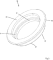
- the protector 10 is shown in a spatial representation.
- the protector 10 is made in this embodiment as a ring made of bronze, in particular, the seal seat 9 has a high accuracy of fit.
- the end face 22 which faces the outside 14 and is first introduced into the shaft passage 4, provided with a ramp 24.
- the protector 10 can then be manufactured with respect to the shaft passage 4 with oversize and be held by means of interference fit, ie by means of adhesion, in the shaft passage 4 of the rear wall 3.
- the axial position is then defined by the stop of the abutment flange 19 on the contact surface 18 of the rear wall 3.
- the protector can not only be used in pumps but also, but not in the context of the disclosed invention, in other coated components to form a stationary seal seat for a mechanical seal assembly. It provides a safe solution for applying a corrosion-resistant seal seat in a coated component such as a centrifugal pump without breaking any corrosion protection of the pump housing or coated component.
- the protector offers a seal seat that is free from corrosion and therefore can be used in a variety of ways.
- the pump or the pump housing / the pump rear wall is protected by the protector from corrosion.
- the protector provides the mating ring of the mechanical seal assembly a stable leadership. This makes it possible to produce the pump housing from less corrosion-resistant material, such as gray cast iron.
- the pump housing may then be completely coated, the coating also covering a transition between the pump housing and the protector to prevent liquid from entering a contact area between the protector and the pump housing. This results in a hundred percent protection of the pump housing from corrosive liquids. Thus all areas of the pump housing coming into contact with the liquid are coated or protected by the protector.
- the protector also offers a corrosion-proof seal seat, which can be manufactured with high accuracy of fit. Even after an exchange of the sealing ring so that a high accuracy of fit is guaranteed, so that leaks are reliably prevented.
- the protector thus allows a pump that can be produced with little effort and from inexpensive materials and yet has a good corrosion protection, so that it can be used to promote corrosive liquids, such as swimming pool water.
Landscapes
- Engineering & Computer Science (AREA)
- Mechanical Engineering (AREA)
- General Engineering & Computer Science (AREA)
- Structures Of Non-Positive Displacement Pumps (AREA)
Priority Applications (1)
| Application Number | Priority Date | Filing Date | Title |
|---|---|---|---|
| PL13180052T PL2706239T3 (pl) | 2012-09-07 | 2013-08-12 | Pompa i protektor pompy |
Applications Claiming Priority (1)
| Application Number | Priority Date | Filing Date | Title |
|---|---|---|---|
| DE102012108354.1A DE102012108354B4 (de) | 2012-09-07 | 2012-09-07 | Pumpe und Protektor für Pumpe |
Publications (3)
| Publication Number | Publication Date |
|---|---|
| EP2706239A2 EP2706239A2 (de) | 2014-03-12 |
| EP2706239A3 EP2706239A3 (de) | 2017-07-26 |
| EP2706239B1 true EP2706239B1 (de) | 2019-06-19 |
Family
ID=48951377
Family Applications (1)
| Application Number | Title | Priority Date | Filing Date |
|---|---|---|---|
| EP13180052.6A Active EP2706239B1 (de) | 2012-09-07 | 2013-08-12 | Pumpe und Protektor für Pumpe |
Country Status (7)
| Country | Link |
|---|---|
| US (1) | US9482238B2 (pl) |
| EP (1) | EP2706239B1 (pl) |
| CA (1) | CA2826219C (pl) |
| DE (1) | DE102012108354B4 (pl) |
| DK (1) | DK2706239T3 (pl) |
| ES (1) | ES2744253T3 (pl) |
| PL (1) | PL2706239T3 (pl) |
Families Citing this family (1)
| Publication number | Priority date | Publication date | Assignee | Title |
|---|---|---|---|---|
| CN108412804B (zh) * | 2018-04-11 | 2024-06-18 | 宜兴市宙斯泵业有限公司 | 一种离心泵用单端面内装式机械密封 |
Citations (1)
| Publication number | Priority date | Publication date | Assignee | Title |
|---|---|---|---|---|
| US3551067A (en) * | 1969-01-22 | 1970-12-29 | Duriron Co | Lined corrosion resistant pump |
Family Cites Families (16)
| Publication number | Priority date | Publication date | Assignee | Title |
|---|---|---|---|---|
| US3604098A (en) * | 1969-11-25 | 1971-09-14 | Irwin C Goldberg | Method of servicing a pump unit |
| US3652183A (en) * | 1970-10-15 | 1972-03-28 | John E Pottharst Jr | Compressor |
| US3841791A (en) * | 1972-05-30 | 1974-10-15 | Worthington Corp | Adaptor and frame for a centrifugal pump |
| US3973867A (en) * | 1975-04-09 | 1976-08-10 | Chien Fu Lee | Radial flow type pump |
| US4722664A (en) * | 1981-06-05 | 1988-02-02 | The Duriron Company, Inc. | Lined corrosion resistant pump |
| US4421456A (en) * | 1982-03-15 | 1983-12-20 | C T Manufacturing, Inc. | Centrifugal pump assembly |
| US4415165A (en) * | 1982-12-02 | 1983-11-15 | The United States Of America As Represented By The Secretary Of The Navy | Integral elastomeric/graphite dynamic face seal |
| US4655684A (en) * | 1984-08-02 | 1987-04-07 | Haentjens Walter D | Centrifugal pump for wide range of operating conditions |
| DE4444968A1 (de) * | 1994-12-16 | 1996-06-20 | Klein Schanzlin & Becker Ag | Kreiselpumpengehäuse mit Innengehäuse aus Kunststoff |
| DE29703739U1 (de) * | 1997-03-01 | 1998-08-13 | H. Wernert & Co. oHG, 45476 Mülheim | Radialpumpe für aggressive Flüssigkeiten |
| DE29723409U1 (de) * | 1997-05-27 | 1998-09-10 | H. Wernert & Co. oHG, 45476 Mülheim | Kreiselpumpe für chemisch aggressive und/oder erosive oder abrasive Fördermedien |
| DE20022573U1 (de) * | 2000-08-29 | 2001-11-22 | Grundfos A/S, Bjerringbro | Kopfaufbau für das Gehäuse einer mehrstufigen Kreiselpumpe |
| US6884022B2 (en) * | 2003-04-25 | 2005-04-26 | General Motors Corporation | Diesel engine water pump with improved water seal |
| JP4633396B2 (ja) * | 2004-07-16 | 2011-02-16 | 株式会社荏原製作所 | 遠心式ポンプ |
| SE531210C2 (sv) * | 2007-05-07 | 2009-01-20 | Roplan Internat Ab | Mekanisk tätningsanordning samt pump |
| ES1073978Y (es) * | 2010-11-23 | 2011-06-09 | Psh 2010 S L U | Bomba centrifuga de flujo mixto para piscinas |
-
2012
- 2012-09-07 DE DE102012108354.1A patent/DE102012108354B4/de not_active Revoked
-
2013
- 2013-08-12 PL PL13180052T patent/PL2706239T3/pl unknown
- 2013-08-12 ES ES13180052T patent/ES2744253T3/es active Active
- 2013-08-12 DK DK13180052.6T patent/DK2706239T3/da active
- 2013-08-12 EP EP13180052.6A patent/EP2706239B1/de active Active
- 2013-09-06 CA CA2826219A patent/CA2826219C/en active Active
- 2013-09-09 US US14/020,955 patent/US9482238B2/en active Active
Patent Citations (1)
| Publication number | Priority date | Publication date | Assignee | Title |
|---|---|---|---|---|
| US3551067A (en) * | 1969-01-22 | 1970-12-29 | Duriron Co | Lined corrosion resistant pump |
Also Published As
| Publication number | Publication date |
|---|---|
| DE102012108354B4 (de) | 2016-05-12 |
| ES2744253T3 (es) | 2020-02-24 |
| CA2826219A1 (en) | 2014-03-07 |
| DE102012108354A1 (de) | 2014-03-13 |
| US20140072409A1 (en) | 2014-03-13 |
| US9482238B2 (en) | 2016-11-01 |
| EP2706239A2 (de) | 2014-03-12 |
| CA2826219C (en) | 2020-08-18 |
| EP2706239A3 (de) | 2017-07-26 |
| PL2706239T3 (pl) | 2019-12-31 |
| DK2706239T3 (da) | 2019-09-16 |
Similar Documents
| Publication | Publication Date | Title |
|---|---|---|
| EP2304246B1 (de) | Vorrichtung zur laufradabdichtung bei kreiselpumpen | |
| DE102013010926A1 (de) | Radialwellendichtung | |
| EP3803125B1 (de) | Magnetgekuppelte pumpe mit doppelschaligem spalttopf | |
| WO2019002206A1 (de) | Schraubenspindelpumpe, kraftstoffförderaggregat und kraftstofffördereinheit | |
| EP2169186B1 (de) | Dichtungsanordnung für die Verdichterseite eines Turboladers einer Verbrennungskraftmaschine sowie entsprechendes Verfahren zur Abdichtung dieser Verdichterseite | |
| EP3438511B1 (de) | Gleitringdichtungsanordnung eines hydrodynamischen retarders sowie hydrodynamischer retarder | |
| DE102011007071A1 (de) | Wellendichtungseinsatz | |
| DE102012108357B4 (de) | Kreiselpumpe und Laufradprotektor für Kreiselpumpe | |
| DE3622963A1 (de) | Pumpe, vorzugsweise behaelterpumpe | |
| DE19960160B4 (de) | Vorrichtung zur Optimierung der Spaltweite bei Kreiselpumpen | |
| EP2745011B1 (de) | Motorpumpeneinheit | |
| EP2707629B1 (de) | Vorrichtung zum abdichten eines pumpraums einer drehkolbenpumpe, sowie drehkolbenpumpe mit selbiger | |
| DE102012108354B4 (de) | Pumpe und Protektor für Pumpe | |
| DE102010044427A1 (de) | Wellendichtung | |
| EP2766608B1 (de) | Kreiselpumpe für feststoffe enthaltende flüssigkeiten mit spaltabdichtung | |
| DE19916370A1 (de) | Kreiselpumpe | |
| EP2433008B1 (de) | Staurohrpumpe | |
| DE2056661A1 (de) | Drehkolbenpumpe für zähflüssige Medien | |
| DE102012213771A1 (de) | Innenzahnradpumpe | |
| EP0588258B1 (de) | Mehrteiliges Stufengehäuse | |
| EP1327781A2 (de) | Selbstansaugende Kreiselpumpe | |
| DE102017100540A1 (de) | Exzenterschneckenpumpe | |
| DE10034195C1 (de) | Baggerpumpe | |
| DE19913632C2 (de) | Flüssigkeitsringpumpe | |
| DE1012183B (de) | Kreiselpumpe, insbesondere zur Foerderung von schleissenden Trueben, Schlaemmen od. dgl. |
Legal Events
| Date | Code | Title | Description |
|---|---|---|---|
| PUAI | Public reference made under article 153(3) epc to a published international application that has entered the european phase |
Free format text: ORIGINAL CODE: 0009012 |
|
| AK | Designated contracting states |
Kind code of ref document: A2 Designated state(s): AL AT BE BG CH CY CZ DE DK EE ES FI FR GB GR HR HU IE IS IT LI LT LU LV MC MK MT NL NO PL PT RO RS SE SI SK SM TR |
|
| AX | Request for extension of the european patent |
Extension state: BA ME |
|
| RAP1 | Party data changed (applicant data changed or rights of an application transferred) |
Owner name: HERBORNER PUMPENTECHNIK GMBH & CO KG |
|
| PUAL | Search report despatched |
Free format text: ORIGINAL CODE: 0009013 |
|
| AK | Designated contracting states |
Kind code of ref document: A3 Designated state(s): AL AT BE BG CH CY CZ DE DK EE ES FI FR GB GR HR HU IE IS IT LI LT LU LV MC MK MT NL NO PL PT RO RS SE SI SK SM TR |
|
| AX | Request for extension of the european patent |
Extension state: BA ME |
|
| RIC1 | Information provided on ipc code assigned before grant |
Ipc: F04D 1/00 20060101ALN20170621BHEP Ipc: F04D 29/02 20060101AFI20170621BHEP Ipc: F04D 29/12 20060101ALI20170621BHEP |
|
| STAA | Information on the status of an ep patent application or granted ep patent |
Free format text: STATUS: REQUEST FOR EXAMINATION WAS MADE |
|
| 17P | Request for examination filed |
Effective date: 20171220 |
|
| RBV | Designated contracting states (corrected) |
Designated state(s): AL AT BE BG CH CY CZ DE DK EE ES FI FR GB GR HR HU IE IS IT LI LT LU LV MC MK MT NL NO PL PT RO RS SE SI SK SM TR |
|
| STAA | Information on the status of an ep patent application or granted ep patent |
Free format text: STATUS: EXAMINATION IS IN PROGRESS |
|
| 17Q | First examination report despatched |
Effective date: 20180516 |
|
| GRAP | Despatch of communication of intention to grant a patent |
Free format text: ORIGINAL CODE: EPIDOSNIGR1 |
|
| STAA | Information on the status of an ep patent application or granted ep patent |
Free format text: STATUS: GRANT OF PATENT IS INTENDED |
|
| RIC1 | Information provided on ipc code assigned before grant |
Ipc: F04D 1/00 20060101ALN20190212BHEP Ipc: F04D 29/12 20060101ALI20190212BHEP Ipc: F04D 29/02 20060101AFI20190212BHEP |
|
| INTG | Intention to grant announced |
Effective date: 20190227 |
|
| RIC1 | Information provided on ipc code assigned before grant |
Ipc: F04D 29/02 20060101AFI20190215BHEP Ipc: F04D 1/00 20060101ALN20190215BHEP Ipc: F04D 29/12 20060101ALI20190215BHEP |
|
| GRAS | Grant fee paid |
Free format text: ORIGINAL CODE: EPIDOSNIGR3 |
|
| GRAA | (expected) grant |
Free format text: ORIGINAL CODE: 0009210 |
|
| STAA | Information on the status of an ep patent application or granted ep patent |
Free format text: STATUS: THE PATENT HAS BEEN GRANTED |
|
| AK | Designated contracting states |
Kind code of ref document: B1 Designated state(s): AL AT BE BG CH CY CZ DE DK EE ES FI FR GB GR HR HU IE IS IT LI LT LU LV MC MK MT NL NO PL PT RO RS SE SI SK SM TR |
|
| REG | Reference to a national code |
Ref country code: GB Ref legal event code: FG4D Free format text: NOT ENGLISH |
|
| REG | Reference to a national code |
Ref country code: CH Ref legal event code: EP |
|
| REG | Reference to a national code |
Ref country code: IE Ref legal event code: FG4D Free format text: LANGUAGE OF EP DOCUMENT: GERMAN |
|
| REG | Reference to a national code |
Ref country code: DE Ref legal event code: R096 Ref document number: 502013013019 Country of ref document: DE |
|
| REG | Reference to a national code |
Ref country code: AT Ref legal event code: REF Ref document number: 1145876 Country of ref document: AT Kind code of ref document: T Effective date: 20190715 |
|
| REG | Reference to a national code |
Ref country code: CH Ref legal event code: NV Representative=s name: VALIPAT S.A., CH Ref country code: CH Ref legal event code: NV Representative=s name: VALIPAT S.A. C/O BOVARD SA NEUCHATEL, CH |
|
| REG | Reference to a national code |
Ref country code: NL Ref legal event code: FP |
|
| REG | Reference to a national code |
Ref country code: DK Ref legal event code: T3 Effective date: 20190912 |
|
| REG | Reference to a national code |
Ref country code: SE Ref legal event code: TRGR |
|
| REG | Reference to a national code |
Ref country code: NO Ref legal event code: T2 Effective date: 20190619 |
|
| PG25 | Lapsed in a contracting state [announced via postgrant information from national office to epo] |
Ref country code: HR Free format text: LAPSE BECAUSE OF FAILURE TO SUBMIT A TRANSLATION OF THE DESCRIPTION OR TO PAY THE FEE WITHIN THE PRESCRIBED TIME-LIMIT Effective date: 20190619 Ref country code: LT Free format text: LAPSE BECAUSE OF FAILURE TO SUBMIT A TRANSLATION OF THE DESCRIPTION OR TO PAY THE FEE WITHIN THE PRESCRIBED TIME-LIMIT Effective date: 20190619 Ref country code: AL Free format text: LAPSE BECAUSE OF FAILURE TO SUBMIT A TRANSLATION OF THE DESCRIPTION OR TO PAY THE FEE WITHIN THE PRESCRIBED TIME-LIMIT Effective date: 20190619 |
|
| REG | Reference to a national code |
Ref country code: LT Ref legal event code: MG4D |
|
| PG25 | Lapsed in a contracting state [announced via postgrant information from national office to epo] |
Ref country code: BG Free format text: LAPSE BECAUSE OF FAILURE TO SUBMIT A TRANSLATION OF THE DESCRIPTION OR TO PAY THE FEE WITHIN THE PRESCRIBED TIME-LIMIT Effective date: 20190919 Ref country code: GR Free format text: LAPSE BECAUSE OF FAILURE TO SUBMIT A TRANSLATION OF THE DESCRIPTION OR TO PAY THE FEE WITHIN THE PRESCRIBED TIME-LIMIT Effective date: 20190920 Ref country code: RS Free format text: LAPSE BECAUSE OF FAILURE TO SUBMIT A TRANSLATION OF THE DESCRIPTION OR TO PAY THE FEE WITHIN THE PRESCRIBED TIME-LIMIT Effective date: 20190619 Ref country code: LV Free format text: LAPSE BECAUSE OF FAILURE TO SUBMIT A TRANSLATION OF THE DESCRIPTION OR TO PAY THE FEE WITHIN THE PRESCRIBED TIME-LIMIT Effective date: 20190619 |
|
| PG25 | Lapsed in a contracting state [announced via postgrant information from national office to epo] |
Ref country code: CZ Free format text: LAPSE BECAUSE OF FAILURE TO SUBMIT A TRANSLATION OF THE DESCRIPTION OR TO PAY THE FEE WITHIN THE PRESCRIBED TIME-LIMIT Effective date: 20190619 Ref country code: RO Free format text: LAPSE BECAUSE OF FAILURE TO SUBMIT A TRANSLATION OF THE DESCRIPTION OR TO PAY THE FEE WITHIN THE PRESCRIBED TIME-LIMIT Effective date: 20190619 Ref country code: EE Free format text: LAPSE BECAUSE OF FAILURE TO SUBMIT A TRANSLATION OF THE DESCRIPTION OR TO PAY THE FEE WITHIN THE PRESCRIBED TIME-LIMIT Effective date: 20190619 Ref country code: PT Free format text: LAPSE BECAUSE OF FAILURE TO SUBMIT A TRANSLATION OF THE DESCRIPTION OR TO PAY THE FEE WITHIN THE PRESCRIBED TIME-LIMIT Effective date: 20191021 Ref country code: SK Free format text: LAPSE BECAUSE OF FAILURE TO SUBMIT A TRANSLATION OF THE DESCRIPTION OR TO PAY THE FEE WITHIN THE PRESCRIBED TIME-LIMIT Effective date: 20190619 |
|
| REG | Reference to a national code |
Ref country code: ES Ref legal event code: FG2A Ref document number: 2744253 Country of ref document: ES Kind code of ref document: T3 Effective date: 20200224 |
|
| PG25 | Lapsed in a contracting state [announced via postgrant information from national office to epo] |
Ref country code: IS Free format text: LAPSE BECAUSE OF FAILURE TO SUBMIT A TRANSLATION OF THE DESCRIPTION OR TO PAY THE FEE WITHIN THE PRESCRIBED TIME-LIMIT Effective date: 20191019 Ref country code: SM Free format text: LAPSE BECAUSE OF FAILURE TO SUBMIT A TRANSLATION OF THE DESCRIPTION OR TO PAY THE FEE WITHIN THE PRESCRIBED TIME-LIMIT Effective date: 20190619 |
|
| PG25 | Lapsed in a contracting state [announced via postgrant information from national office to epo] |
Ref country code: TR Free format text: LAPSE BECAUSE OF FAILURE TO SUBMIT A TRANSLATION OF THE DESCRIPTION OR TO PAY THE FEE WITHIN THE PRESCRIBED TIME-LIMIT Effective date: 20190619 |
|
| PG25 | Lapsed in a contracting state [announced via postgrant information from national office to epo] |
Ref country code: MC Free format text: LAPSE BECAUSE OF FAILURE TO SUBMIT A TRANSLATION OF THE DESCRIPTION OR TO PAY THE FEE WITHIN THE PRESCRIBED TIME-LIMIT Effective date: 20190619 Ref country code: IS Free format text: LAPSE BECAUSE OF FAILURE TO SUBMIT A TRANSLATION OF THE DESCRIPTION OR TO PAY THE FEE WITHIN THE PRESCRIBED TIME-LIMIT Effective date: 20200224 Ref country code: LU Free format text: LAPSE BECAUSE OF NON-PAYMENT OF DUE FEES Effective date: 20190812 |
|
| REG | Reference to a national code |
Ref country code: BE Ref legal event code: MM Effective date: 20190831 |
|
| REG | Reference to a national code |
Ref country code: DE Ref legal event code: R097 Ref document number: 502013013019 Country of ref document: DE |
|
| PLBE | No opposition filed within time limit |
Free format text: ORIGINAL CODE: 0009261 |
|
| STAA | Information on the status of an ep patent application or granted ep patent |
Free format text: STATUS: NO OPPOSITION FILED WITHIN TIME LIMIT |
|
| PG2D | Information on lapse in contracting state deleted |
Ref country code: IS |
|
| PG25 | Lapsed in a contracting state [announced via postgrant information from national office to epo] |
Ref country code: IE Free format text: LAPSE BECAUSE OF NON-PAYMENT OF DUE FEES Effective date: 20190812 |
|
| 26N | No opposition filed |
Effective date: 20200603 |
|
| PG25 | Lapsed in a contracting state [announced via postgrant information from national office to epo] |
Ref country code: SI Free format text: LAPSE BECAUSE OF FAILURE TO SUBMIT A TRANSLATION OF THE DESCRIPTION OR TO PAY THE FEE WITHIN THE PRESCRIBED TIME-LIMIT Effective date: 20190619 Ref country code: BE Free format text: LAPSE BECAUSE OF NON-PAYMENT OF DUE FEES Effective date: 20190831 |
|
| PG25 | Lapsed in a contracting state [announced via postgrant information from national office to epo] |
Ref country code: CY Free format text: LAPSE BECAUSE OF FAILURE TO SUBMIT A TRANSLATION OF THE DESCRIPTION OR TO PAY THE FEE WITHIN THE PRESCRIBED TIME-LIMIT Effective date: 20190619 |
|
| PG25 | Lapsed in a contracting state [announced via postgrant information from national office to epo] |
Ref country code: MT Free format text: LAPSE BECAUSE OF FAILURE TO SUBMIT A TRANSLATION OF THE DESCRIPTION OR TO PAY THE FEE WITHIN THE PRESCRIBED TIME-LIMIT Effective date: 20190619 Ref country code: HU Free format text: LAPSE BECAUSE OF FAILURE TO SUBMIT A TRANSLATION OF THE DESCRIPTION OR TO PAY THE FEE WITHIN THE PRESCRIBED TIME-LIMIT; INVALID AB INITIO Effective date: 20130812 |
|
| PG25 | Lapsed in a contracting state [announced via postgrant information from national office to epo] |
Ref country code: MK Free format text: LAPSE BECAUSE OF FAILURE TO SUBMIT A TRANSLATION OF THE DESCRIPTION OR TO PAY THE FEE WITHIN THE PRESCRIBED TIME-LIMIT Effective date: 20190619 |
|
| PGFP | Annual fee paid to national office [announced via postgrant information from national office to epo] |
Ref country code: NL Payment date: 20250821 Year of fee payment: 13 |
|
| PGFP | Annual fee paid to national office [announced via postgrant information from national office to epo] |
Ref country code: FI Payment date: 20250822 Year of fee payment: 13 Ref country code: ES Payment date: 20250926 Year of fee payment: 13 |
|
| PGFP | Annual fee paid to national office [announced via postgrant information from national office to epo] |
Ref country code: DK Payment date: 20250825 Year of fee payment: 13 Ref country code: DE Payment date: 20250831 Year of fee payment: 13 |
|
| PGFP | Annual fee paid to national office [announced via postgrant information from national office to epo] |
Ref country code: NO Payment date: 20250826 Year of fee payment: 13 |
|
| PGFP | Annual fee paid to national office [announced via postgrant information from national office to epo] |
Ref country code: IT Payment date: 20250825 Year of fee payment: 13 Ref country code: PL Payment date: 20250811 Year of fee payment: 13 |
|
| PGFP | Annual fee paid to national office [announced via postgrant information from national office to epo] |
Ref country code: GB Payment date: 20250820 Year of fee payment: 13 |
|
| PGFP | Annual fee paid to national office [announced via postgrant information from national office to epo] |
Ref country code: FR Payment date: 20250829 Year of fee payment: 13 Ref country code: AT Payment date: 20250821 Year of fee payment: 13 |
|
| PGFP | Annual fee paid to national office [announced via postgrant information from national office to epo] |
Ref country code: CH Payment date: 20250901 Year of fee payment: 13 Ref country code: SE Payment date: 20250820 Year of fee payment: 13 |